

Dr. Mach LED 115 Instructions For Use Manual
Mach LED 115
Dr. Mach
Lamps and Engineering
59060001
Edition 01
02.08.2012 / Bak Page 1/15
Instructions for use
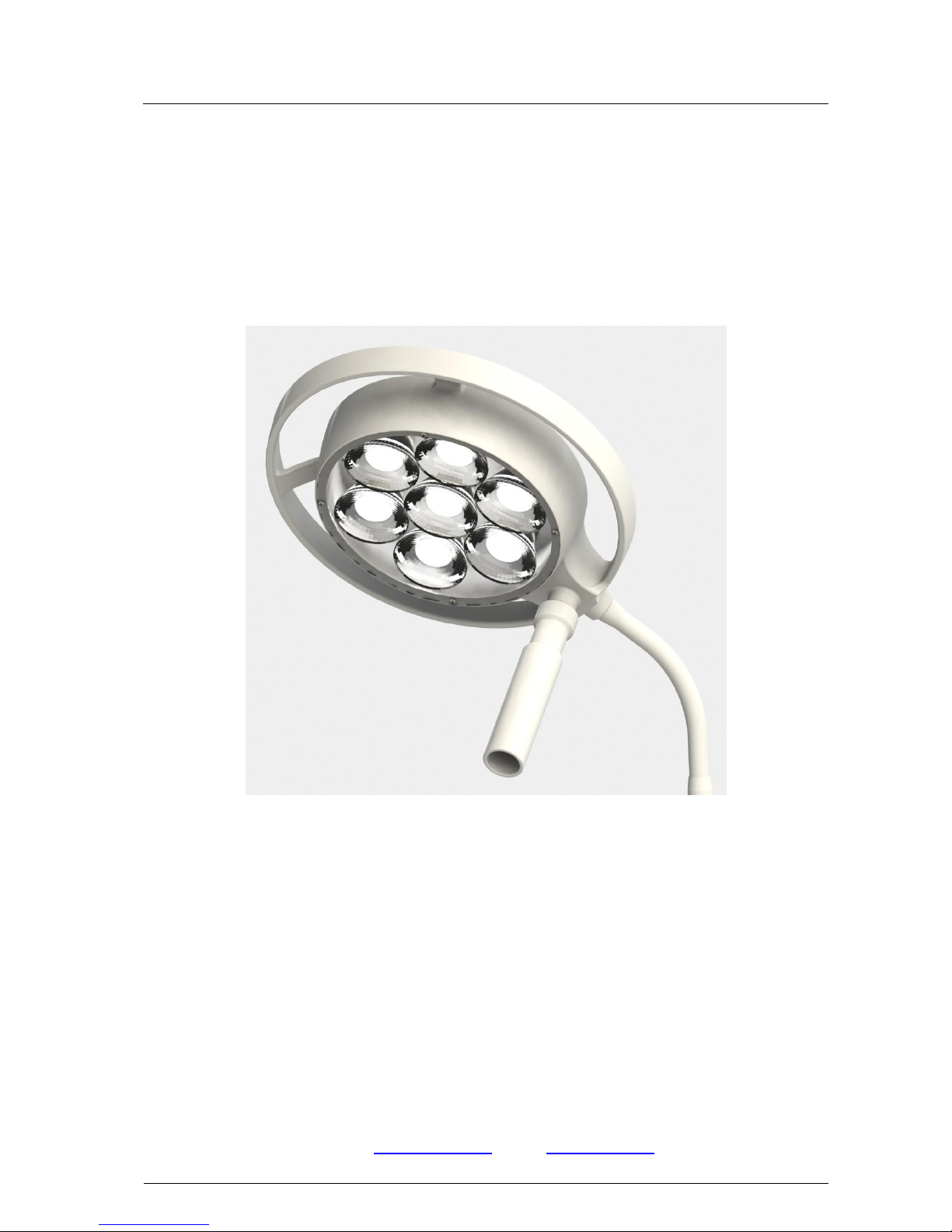
MACH LED 115
Spot Light with LED Technology
LED 115 stand model ............................................................................. Item no. 1153101200
LED 115 wall model ................................................................................ Item no. 1153102100
Special fixations:
LED 115 with fixation with table clamp ................................................. Item no. 1153102500
LED 115 with fixation clamp for supply rails ........................................ Item no. 1153102601
LED 115 with fixation for round and square tubes............................... Item no. 1153102602
LED 115 with fixation plate .................................................................... Item no. 1153102604
Dr. Mach GmbH u. Co., Flossmannstrasse 28, D-85560 Ebersberg
Tel.: +49 (0)8092 2093 0, Fax +49 (0)8092 2093 50
Internet: www.dr-mach.com, E-mail: info@dr-mach.de

Mach LED 115
Dr. Mach
Lamps and Engineering
59060001
Edition 01
02.08.2012 / Bak Page 2/15
List of contents
1. Safety instructions ........................................................................................ page 3
2. Mounting instructions .................................................................................... page 4
2.1 Mounting the mobile stand ...................................................................... page 4
2.2 Mounting the light ................................................................................... page 5
2.3 Wall attachment ...................................................................................... page 5
2.4 Table attachment .................................................................................... page 5
2.5 Rail attachment ....................................................................................... page 5
2.6 Round and rectangular tube attachment ................................................. page 5
2.7 Fixation of screw-on plate ...................................................................... page 5
3. Directions for use.......................................................................................... page 6
3.1 Stand foot ............................................................................................... page 6
3.2 Stand tube .............................................................................................. page 6
3.3 Operating the light .................................................................................. page 7
3.3.1 ON/OFF switch................................................................................ page 7
3.3.2 Positioning ...................................................................................... page 7
3.3.3 Electronic light intensity control ....................................................... page 8
4. Cleaning ....................................................................................................... page 8
4.1 Mobile stand ........................................................................................... page 8
4.2 Light head ............................................................................................... page 8
4.3 Protection disk ........................................................................................ page 8
5. Maintenance ................................................................................................. page 9
5.1 Periodical maintenance work .................................................................. page 9
5.2 Settings at the light arm .......................................................................... page 9
5.3 Settings at the mobile stand.................................................................... page 9
6. Data ............................................................................................................. page 10
6.1 Technical data ........................................................................................ page 10
6.2 Electrical data ......................................................................................... page 11
6.3 Environmental conditions ........................................................................ page 11
7. CE-mark ....................................................................................................... page 12
8. Disposal ....................................................................................................... page 12
9. Electromagnetic compatibility ....................................................................... page 13

Mach LED 115
Dr. Mach
Lamps and Engineering
59060001
Edition 01
02.08.2012 / Bak Page 3/15
1. Safety instructions
Please pay attention to the directions for use when handling the lamp.
Attention:
This device is not suitable for use in hazardous locations.
The lamp is classified as a group 1 device according to the MPG
(law for medical products).
The lamp may be connected to mains only after the complete mounting of the stand
and the lamp.
Repairs to the lamp and special installation work at the electronic power supply
should only be carried out by ourselves or a company expressly authorised by ourselves.
The manufacturer is only responsible for the safety of the lamp and the stand if repairs
and alterations have been carried out by themselves or a company who can guarantee
that the safety regulations have been observed.
The manufacturer is not liable for personal or material damages if the lamp or the
stand is misappropriate or incorrectly operated or misused.
General instructions
All Dr. Mach stand lamps are supplied with
all installation and connection parts and
components.
For packaging reasons, the five-foot stand is
supplied in dismantled state. The stand tube
is always assembled as a unit and only
needs to be attached to the foot with the
lower fastening screw.
The lamp is supplied with integrated connection lead and earthed plug.
The socket to be used for the lamp must be
installed according to the requirements stipulated by the IEC or VDE 0100-710.
Please check that the earthed socket is
available within the working area of the lamp.
Mach LED 115
Dr. Mach
Lamps and Engineering
59060001
Edition 01
02.08.2012 / Bak Page 4/15
2. Mounting instructions
Extent of supply
1x 5-footed plastic central base
2x extension arms with blocking rollers
2x extension arms with electrically conductive rollers
1x extension arm with roller
1x cam catch plate
1x cheese head screw M8 with lock washer
1x stand tube
Lamp head with arm
Mounting instructions/Instructions for use – lamp head and stand
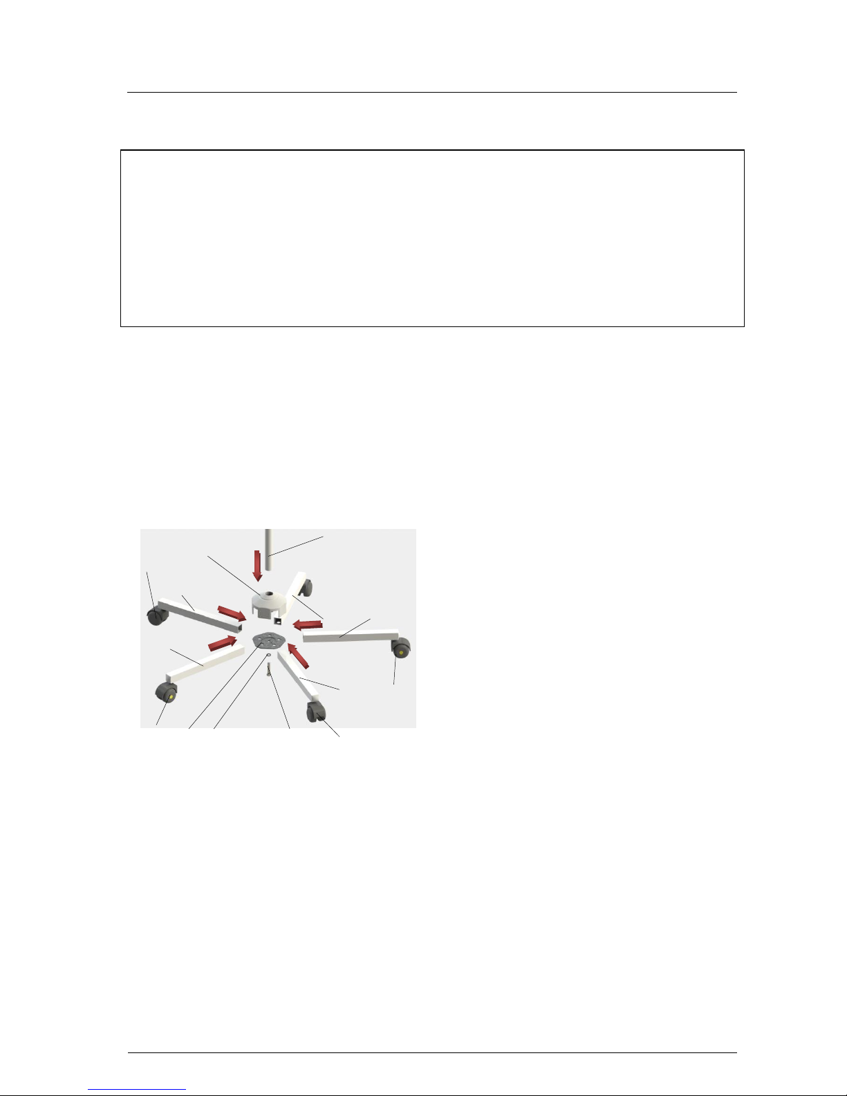
2.1 Mounting the mobile stand
For mounting the stand proceed as follows:
Place the central base 1 onto the stand
tube 25 2. The stiffness is to ensure a
tight fit that is free from any movement.
Pre-mount the cam catch plate 3 (cams
point inwards), with the lock washer 4 and
cheese head screw M8 5, so that the extension arm 6 can still fit easily into the
central base. Insert the extension arm 6 into the central base from above holding the
cam catch plate 3 against from the opposite side.
Insert the other 4 extension arms 7-10 in
the sequence shown in the left figure into
the central base. The extension arms are
held by the cams of the cam catch plates.
Remark: Mount the two locking rollers 11
and 12, and the two electrically conductive
rollers 13 and 14 as shown in the figure (not
next to each other).
Tighten the catch plate with an Allen key
SW6 (approx. 15Nm).
The cams of the catch plate must mate with
the drill holes of the extension arms so that
every extension arm is tightly fitted to both
the central base and stand tube.
The cams also prevent the extension arms
from being pulled out.
2 1 5 4 3
6 7 8 9 10
11
12
13
14
Mach LED 115
Dr. Mach
Lamps and Engineering
59060001
Edition 01
02.08.2012 / Bak Page 5/15
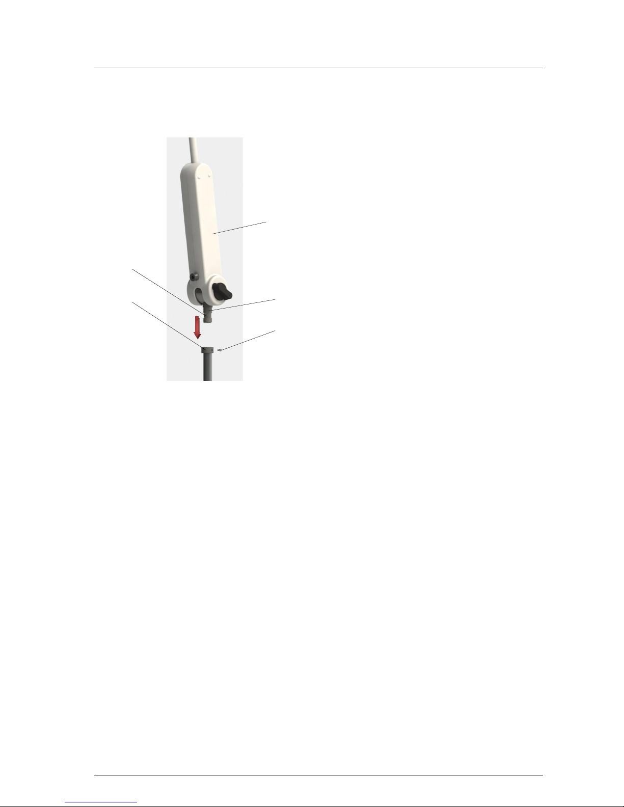
2.2 Mounting the light
Tighten screw S in the mounting device (stand,
wall, table, rail, round and rectangular tube,
screw-on plate) after the lamp has been attached. This prevents the lamp from being unintentionally removed.
Make sure that joint Z at the lower side of
transformer housing 14 is fully inserted into
tube A, so that the safety screw S engages
properly in the provided groove N.
2.3 Wall attachment
Mark the position of the holes to be drilled in the wall using the wall bracket.
Drill the holes and insert dowels provided by the customer. Dr. Mach does not include dow-
els in the scope of supply.
For mounting the lamp see point 2.2.
2.4 Table attachment
Screw table clamp onto table.
For mounting the lamp see point 2.2.
2.5 Rail attachment
Attach light mounting in the desired position on the rail.
For mounting the lamp see point 2.2.
2.6 Round and rectangular tube attachment
Screw light mounting in desired position onto tube.
For mounting the lamp see point 2.2.
2.7 Attachment of screw-on plate
Drill attachment holes and attach with screws.
For mounting the lamp see point 2.2.
S
14
A N Z
 Loading...