

Ceiling and wall attachment
Dr. Mach
Lamps and Engineering
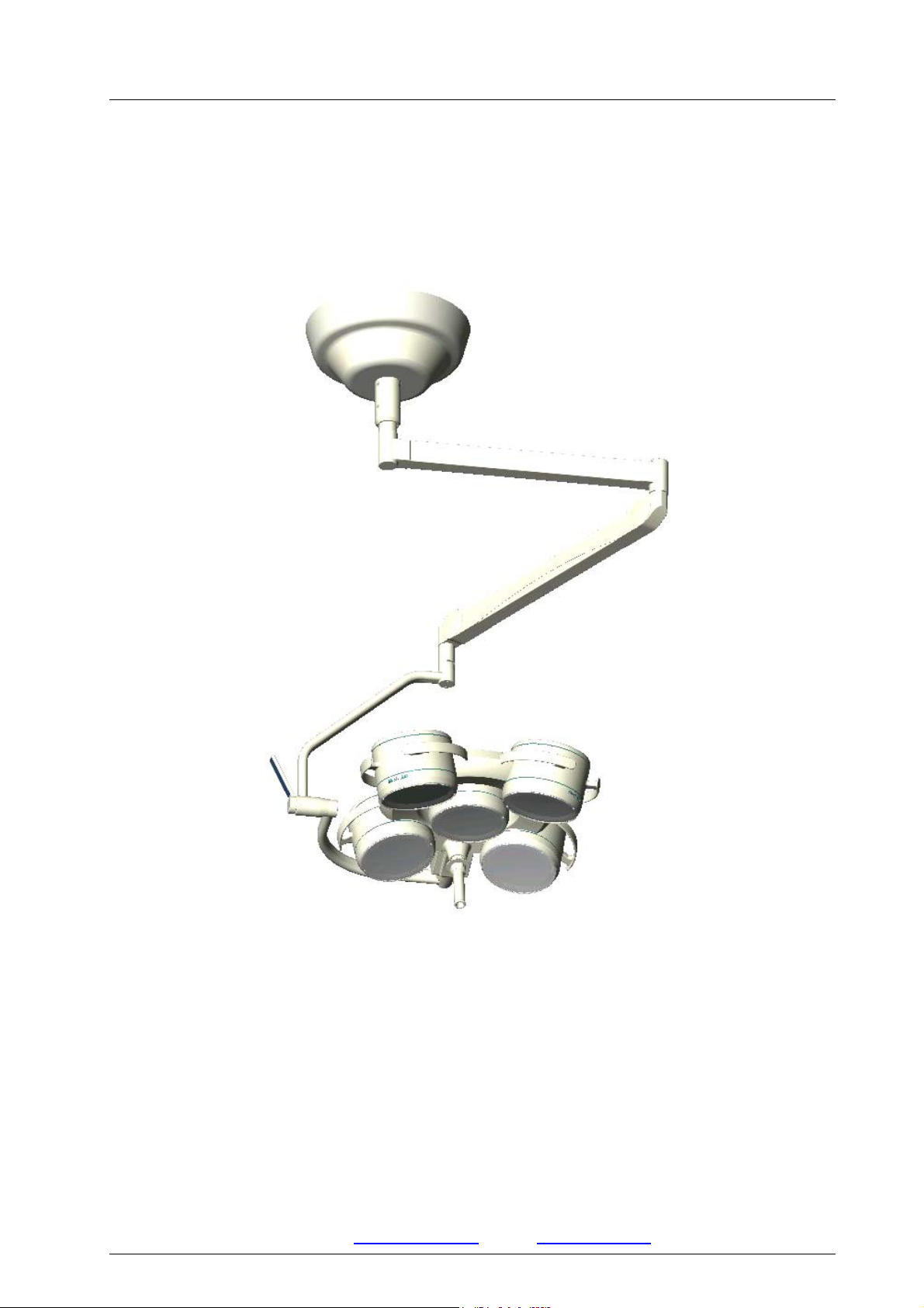
MMOOUUNNTTIINNGG IINNSSTTRRUUCCTTIIOONNSS
CCeeiilliinngg aattttaacchhmmeenntt W
Waallll aattttaacchhmmeenntt
Applies to:
Dr. Mach GmbH u. Co., Flossmannstrasse 28, D-85560 Ebersberg
Tel.: +49 (0)8092 2093 0, Fax +49 (0)8092 2093 50
Internet: www.dr-mach.com, E-mail: info@dr-mach.de
59500001 Edition 06 11.03.2003 / Bak Page 1/48
Soloflex
Triaflex
Trigenflex
Quintaflex
Mach 120
Mach 130
Mach M3
Mach M5
Mach 380
Mach 400
Mach 500
Tool and instrument trays

Ceiling and wall attachment
These mounting instructions must be kept together
with the lamp’s operating instructions for reference.
General instructions
All Dr. Mach lamps are supplied with a flange with
a graduated circle diameter 270mm and six bores
diameter 15mm. The flange supports the vertical
suspension tube. It is attached to the solid ceiling
by means of a ceiling anchorage ring.
Remark: The ceiling anchorage ring has to be
ordered separately!
The ceiling anchorage ring has six precisely positioned threaded bolts M12. It makes it possible to
fasten and adjust the lamp without causing dust or
dirt after all building work has been completed. The
use of a ceiling anchorage ring is necessary in all
cases of ceiling attachments.
During mounting, take care to ensure that neither
the flange nor the attachment elements are in contact with reinforcement components of the solid
ceiling.
In view of the slight weight of the Dr. Mach lamps,
it is not fundamentally necessary to drill through
the ceiling and use a counter-plate. Ceiling anchorage rings can be attached without any problems to ceilings in the concrete strength class
greater than or equal to B25, using safety dowels
M8.
Depending on the stability of the location, it may be
necessary to use a counter-plate for the wall attachment.
Dr. Mach
Lamps and Engineering
The forces arising when the widely extending articulated arms tilt, do make it necessary to drill very
carefully with a certified hammer drill, paying close
attention to the drilling tolerances.
The suspension tube of the lamp or lamp combination must be adjusted vertically to prevent the lamp
body from moving. For this purpose the M12
counter nuts on the attaching bolts must be adjusted accordingly.
In case of false ceilings, the suspension tubes for
all lamps can be mounted directly through to the
solid ceiling. The opening required for this purpose
can be closed once the work has been completed,
using the canopy diameter 450mm or a covering
plate.
When using an intermediate flange (preferably for
spaces exceeding 400mm and for room heights
exceeding 4050mm), the length of the intermediate
flange is to be measured to the lower edge of the
false ceiling.
Also in this case a ceiling anchorage ring has to be
used for fixation.
59500001 Edition 06 11.03.2003 / Bak Page 2/48

Ceiling and wall attachment
Dr. Mach
Lamps and Engineering
List of contents
1. Mounting layout ceiling attachment .......................................................................... Page 6
2. Ceiling attachment.................................................................................................... Page 7
2.1 Preparatory work on the ceiling ......................................................................... Page 7
2.1.1 Setting the safety dowels .......................................................................... Page 7
2.1.2 Mounting the ceiling anchorage ring
to the solid ceiling ...................................................................................... Page 7
2.2 Pre-mounting of the ceiling flange and suspension tube................................... Page 8
2.2.1 Aluminium cast flange and suspension tube ∅ 50mm..............................Page 8
2.2.2 Flange tube ∅ 70mm and suspension tube ∅ 50mm ............................... Page 9
2.2.3 Light-weighted central axis
(connection which can turn through 360°) ................................................. Page 10
2.2.4 Ceiling attachments and room heights......................................................Page 11
2.3 Mounting the flange and suspension tube to the ceiling.................................... Page 13
3. Mounting layout wall attachment .............................................................................. Page 15
4. Wall attachment........................................................................................................ Page 16
4.1 Preparatory work on the wall ............................................................................. Page 16
4.2 Mounting the wall bearing.................................................................................. Page 17
4.2.1 Wall attachment, room heights.................................................................. Page 18
4.3 Installing the extension arm stop (surcharge).................................................... Page 19
5. Electrical connection ................................................................................................Page 20
5.1 Preparing the electrical connection.................................................................... Page 21
5.2 Electrical connection for lamps with external transformer .................................Page 21
5.2.1 Ceiling lamps with external transformer .................................................... Page 21
5.2.2 Wall lamps with external transformer ........................................................ Page 22
5.2.3 Lamps with regulating transformer............................................................Page 23
5.3 Wiring diagrams................................................................................................. Page 24
6. Mounting the articulated arms .................................................................................. Page 25
6.1 Ceiling attachment............................................................................................. Page 25
6.1.1 Mounting the extension arm...................................................................... Page 25
6.1.2 Removing the lateral covering plates ........................................................ Page 25
6.1.3 Electrical connection ................................................................................. Page 26
6.2 Wall attachment................................................................................................. Page 27
6.3 Mounting the spring arms .................................................................................. Page 27
6.3.1 Mounting the standard spring arm ............................................................Page 27
6.3.2 Mounting the Space spring arm ................................................................ Page 28
6.3.3 Mounting the central spring arm................................................................ Page 29
7. Mounting the lamp / the end device .........................................................................Page 30
7.1 Mounting at the standard spring arm................................................................. Page 30
7.2 Mounting at the Space spring arm..................................................................... Page 32
7.3 Mounting at the central spring arm .................................................................... Page 33
8. Adjusting the mobility ...............................................................................................Page 35
8.1 Adjusting the mobility at the ceiling attachment................................................. Page 35
8.2 Adjusting the spring force .................................................................................. Page 36
8.2.1 Standard-spring arm .................................................................................Page 36
8.2.2 Space spring arm ...................................................................................... Page 37
8.2.3 Central spring arm..................................................................................... Page 37
59500001 Edition 06 11.03.2003 / Bak Page 3/48

Ceiling and wall attachment
8.3 Height adjustment ............................................................................................. Page 39
8.3.1 Standard-spring arm ................................................................................. Page 39
8.3.2 Space spring arm...................................................................................... Page 40
8.3.3 Central spring arm .................................................................................... Page 40
9. Maintenance ............................................................................................................ Page 41
10. CE –mark ............................................................................................................... Page 41
11. Spare parts ............................................................................................................ Page 42
12. Spare parts list ....................................................................................................... Page 45
Dr. Mach
Lamps and Engineering
59500001 Edition 06 11.03.2003 / Bak Page 4/48

Ceiling and wall attachment
Dr. Mach
Lamps and Engineering
Static inspection
Note:
The static (structural) inspection must be carried out before the installation of the
ceiling or wall anchorage!
- The strength of the construction must be designed, checked and certified by a structural
engineer.
- The respective regional construction regulations that apply must be followed.
- If a wrong hole is drilled by mistake, e.g. drilling of a reinforcement rod, the structural engi-
neer who is responsible must be contacted, since adequate static load distribution in the ceiling may have been endangered.
Declaration of acceptance:
It is hereby certified that the supporting ceiling / wall and the ceiling anchoring / wall anchoring
is safe and adequately strong.
Project: ____________________________________________________________________
____________________________________________________________________________
____________________________________________________________________________
Anchoring (please check the one that is applicable)
- with dowels authorized by construction authority
- with counter-plate
- other
Location: ____________________________________________
Signature / Stamp: (structural engineer / construction authority)
59500001 Edition 06 11.03.2003 / Bak Page 5/48
Ceiling and wall attachment
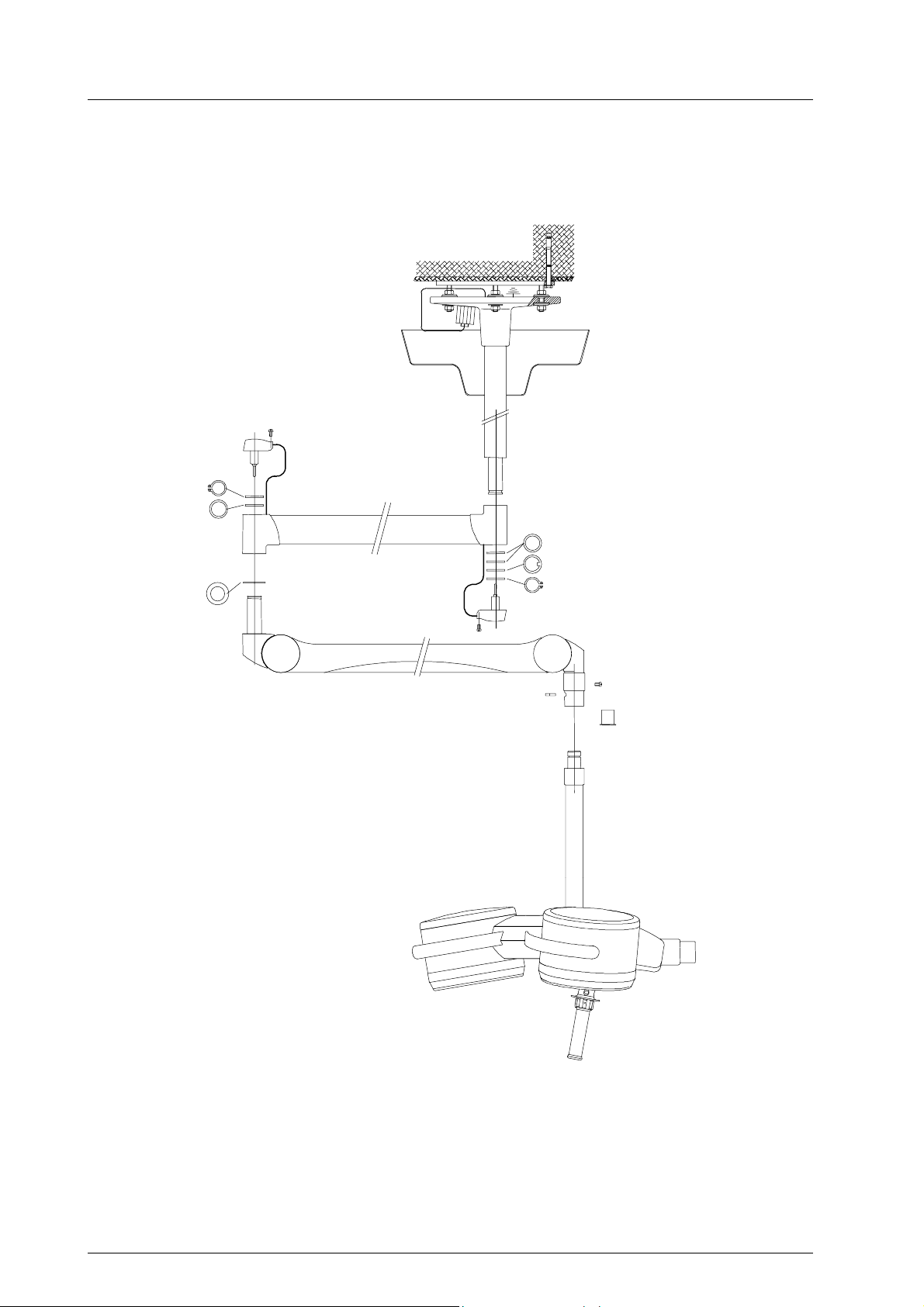
1. Mounting layout
Flange
Bracket
Dr. Mach
Lamps and Engineering
Ceiling attachment
Ceiling anchorage ring
Intermediate flange (option)
Canopy
Suspension tube with axis
Levelling washer (Remark!)
Gib washer 1x
Circlip 1x
Spring arm
OT -lamp
Remark:
One levelling washer is always necessary.
If the distance between bracket and spring arm is too big, use the second levelling washer.
The circlip (Seegerring) must be easy to mount and has to snap in. It should turn easily in the groove.
59500001 Edition 06 11.03.2003 / Bak Page 6/48
Ceiling and wall attachment
Dr. Mach
Lamps and Engineering
2. Ceiling attachment
2.1 Preparatory work on the ceiling
2.1.1 Setting the safety dowels
Attention:
Lamps, ceiling anchorage rings and intermediate flanges may only be attached to a ceiling of
concrete strength class greater than or equal to B25. In case of light-weight ceiling coverings,
the dowel anchor must be sunk completely into the concrete. To bridge this space use long
threaded bolts for attaching the ceiling tube.
In addition, take care that neither suspension tube nor attaching elements come into contact
with reinforcement components of the solid ceiling.
The lamp weight and the tilt of the long articulated arm(s) require that this work is performed
meticulously. This refers particularly to the use of a certified hammer drill and to observe the
drilling tolerances.
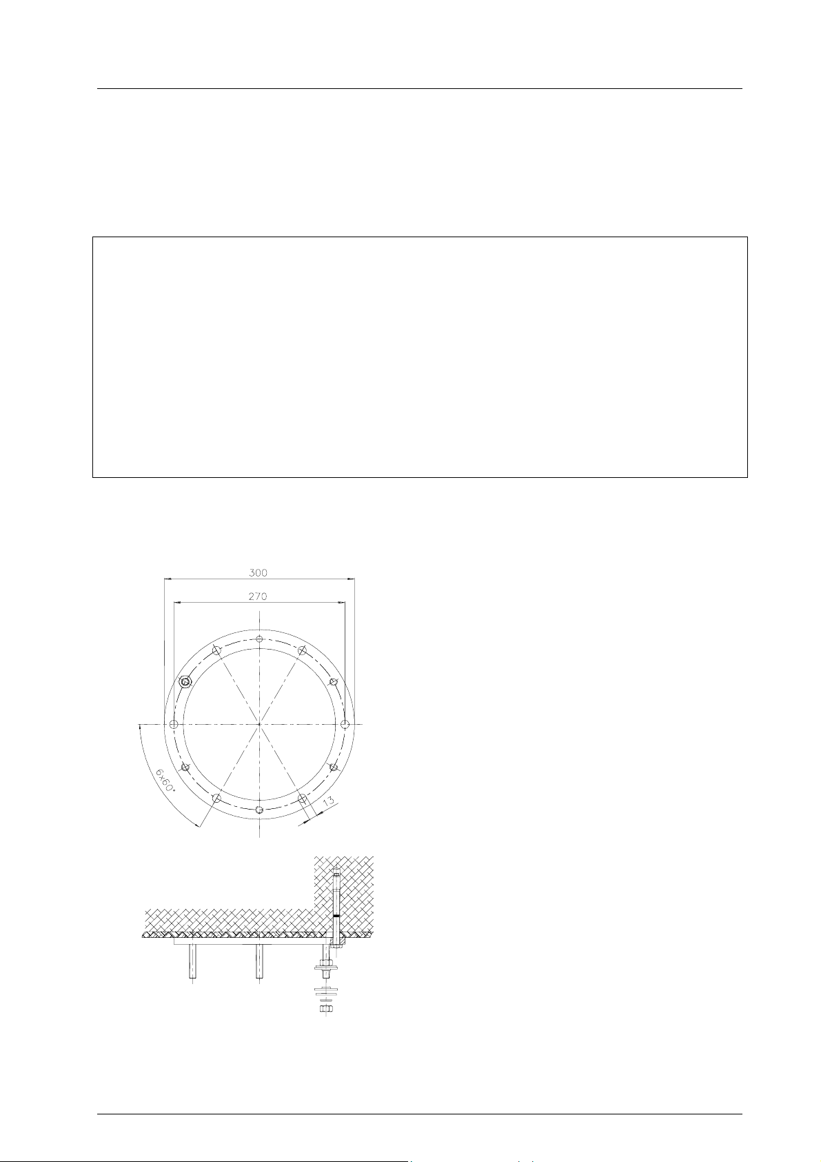
2.1.2 Mounting the ceiling anchorage ring to the solid ceiling
The scope of supply includes:
1 attachment set, consisting of:
• Six safety dowels Fischer FHA 12/50 galZn
• Mounting data Fischer
• Bore template
To attach the ceiling anchorage ring to a solid ceiling proceed as follows:
• Drill the bore holes according to the figure diameter 12mm and at least 100mm deep with a
certified hammer drill, using the enclosed bore
template. You can also use the ceiling anchorage ring as a template. In this case a second
person may be needed to assist.
• Insert the safety dowels through the bores of
the ceiling anchorage ring in such a way, that
the washers lie flat to the ring.
• Tighten the screws carefully using a torque
wrench (25Nm).
Light-weight ceiling panelling with a maximum
thickness of 30mm can be bridged using the enclosed safety dowels. For panelling thicker than
30mm, it is necessary to remove the panelling before mounting.
59500001 Edition 06 11.03.2003 / Bak Page 7/48
Ceiling and wall attachment
Dr. Mach
Lamps and Engineering
2.2 Pre-assembly of the ceiling flange and suspension tube
and installing the electrical connections
The length of the suspension tube is adjusted to the required room height with a clearance height of at
least 200cm under the lamp.
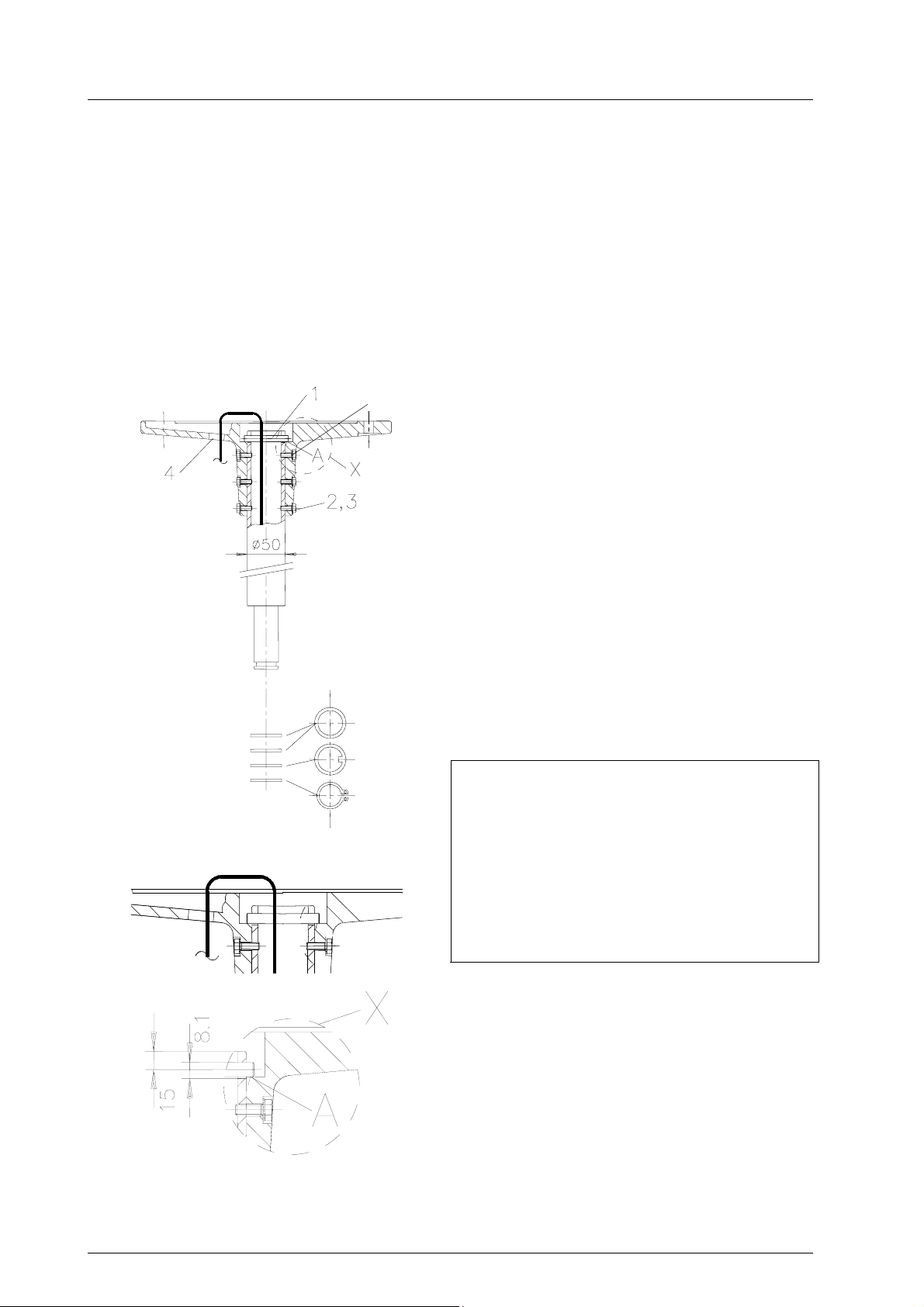
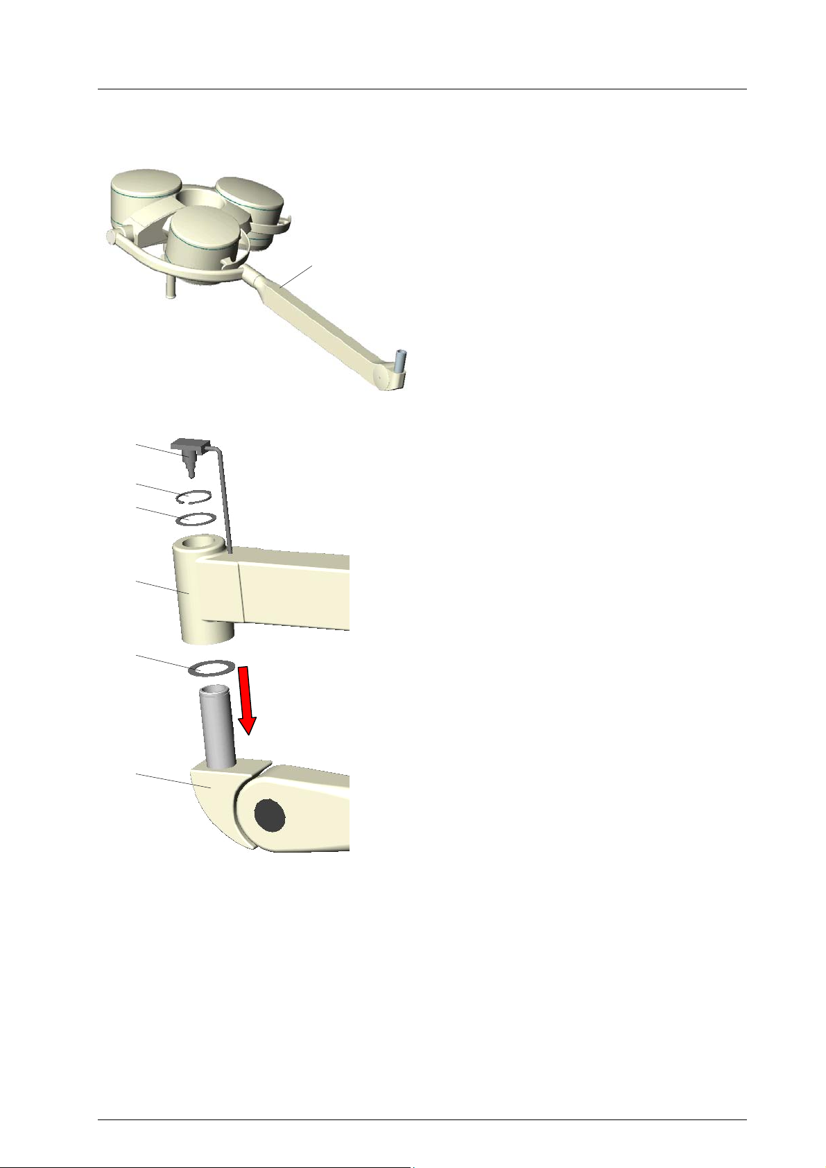
2.2.1 Aluminium cast flange and suspension tube ∅ 50mm
For the double models, slide the canopy (if not divided) and the ring over the corresponding suspension
tube before mounting the ceiling bearing. This step is not necessary for the single models as the canopy
can be slid into place after mounting the suspension to the ceiling.
1
Standard version
The diagram shows the single model and applies in
the same way to the double and triple models.
• Cable or cord showing out the suspension tube
is to be pushed carefully into the ceiling flange
together with the suspension tube.
• Push the suspension tube upwards until the
safety pin 1 can be pushed through the cross
bores of the suspension tube.
• Then pull the suspension tube down until the
safety pin 1 lies in recess A of the ceiling
flange.
• Then secure the connection with six screws 2
and washers 3 to prevent wobbling. If not possible, turn suspension tube by 180°.
• Pull the cable or cord through the bore 4 as
shown in the diagram.
Note:
The suspension tube is delivered with premounted retaining ring for the ceiling canopy.
Each connection journal is also equipped
with:
• 2 spacer rings
• 1 gib ring
• 1 circlip (Seegerring)
59500001 Edition 06 11.03.2003 / Bak Page 8/48
Ceiling and wall attachment
Dr. Mach
Lamps and Engineering
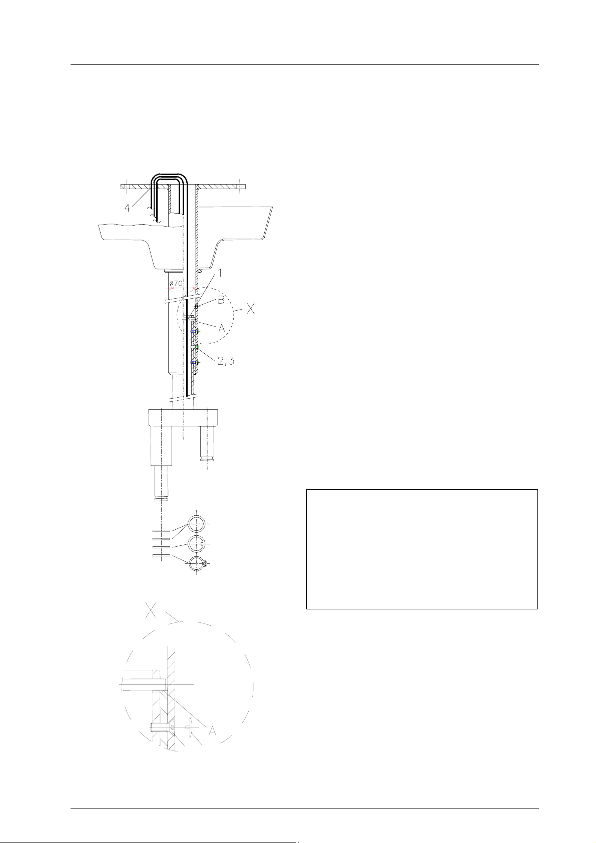
2.2.2 Flange tube ∅ 70mm
When necessary (in case of very high rooms or heavy lightning systems) a welded construction is used in
which the ceiling flange is welded to a tube. Also for double and triple types, slide the canopy (if not divided) and the ring over the flange tube before mounting the suspension tube.
Standard version
The diagram shows the triple model and applies in
the same way to the single and double models.
• Cable or cord showing out the suspension tube
is to be pushed carefully into the ceiling flange
together with the suspension tube.
• Push the suspension tube down until the safety
bolt 1 can be pushed through bore B of the
flange pipe into the cross bores of the suspension tube.
• Then pull the suspension tube down until the
safety bolt lies in recess A of the ceiling flange.
• Then secure the connection with six countersunk screws M6x16 2 (tool: hexagonal socket
wrench) to prevent wobbling. If not possible,
turn suspension tube by 180°.
• Pull the cable or cord through the bore 4 as
shown in the diagram.
• Fix the covers 5 on screws 2.
• Put the two covers on the bores B.
The table on page 9 shows the recommended distance between floor and suspension tube.
Please check this distance when mounting the
lamp.
Note:
The suspension tube is delivered with premounted retaining ring for the ceiling canopy.
Each connection journal is also equipped
with:
• 2 spacer rings
• 1 gib ring
• 1 circlip (Seegerring)
2 5
59500001 Edition 06 11.03.2003 / Bak Page 9/48
Ceiling and wall attachment
Dr. Mach
Lamps and Engineering
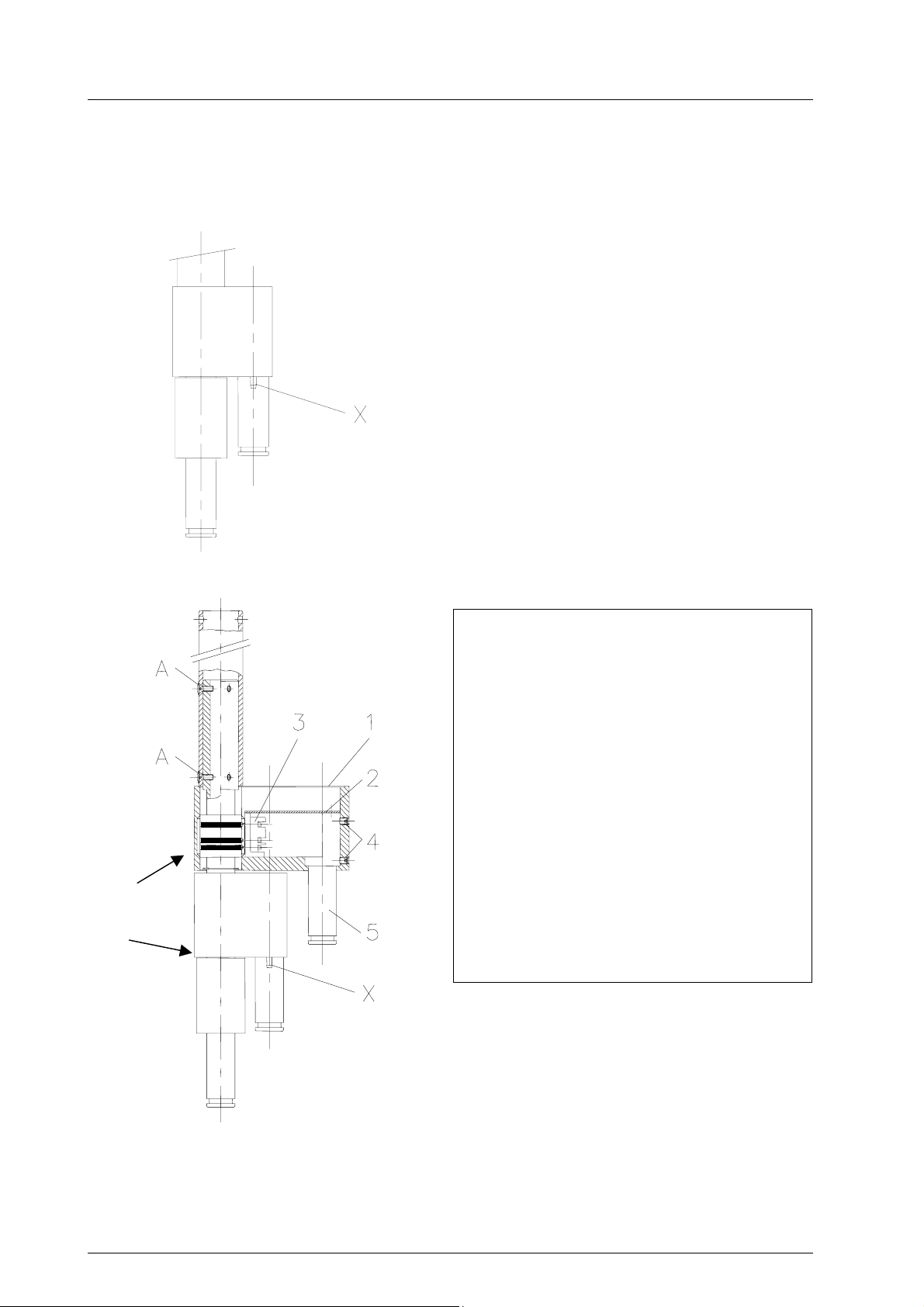
2.2.3 Light weighted central axis (connection which can turn through 360°)
The pre-assembly instructions given on chapter 3.2 also apply here.
Bremsen
M8x12
DIN 915
Double model (can turn through 360°)
The suspension tubes which can turn through 360°
are supplied ready mounted and wired. The length
is usually already adjusted according to the room
height.
Before mounting, check that the six threaded pins A
of the pre-assembled connections are properly
fixed.
X plugger pin for articulated arm
(see remark at the mounting instructions for ar ticulated arms on page 18).
Triple model (can turn through 360°)
See above.
Instructions for replacing
the sliding contact set
(only when required)
• Loosen cover 1 and swivel away to the
side.
• Loosen the four threaded pins M8 4, so
that the coupling journal 5 is loose.
• Take off safety plate 2.
• Loosen sliding contact set 3.
• Remove together coupling journal 5 and
sliding contact set.
• Replace sliding contact set.
• Remount in reverse order.
Note:
This procedure is basically the same for the
triple and double bracket, apart from more
constricted space in the double bracket.
59500001 Edition 06 11.03.2003 / Bak Page 10/48
Ceiling and wall attachment
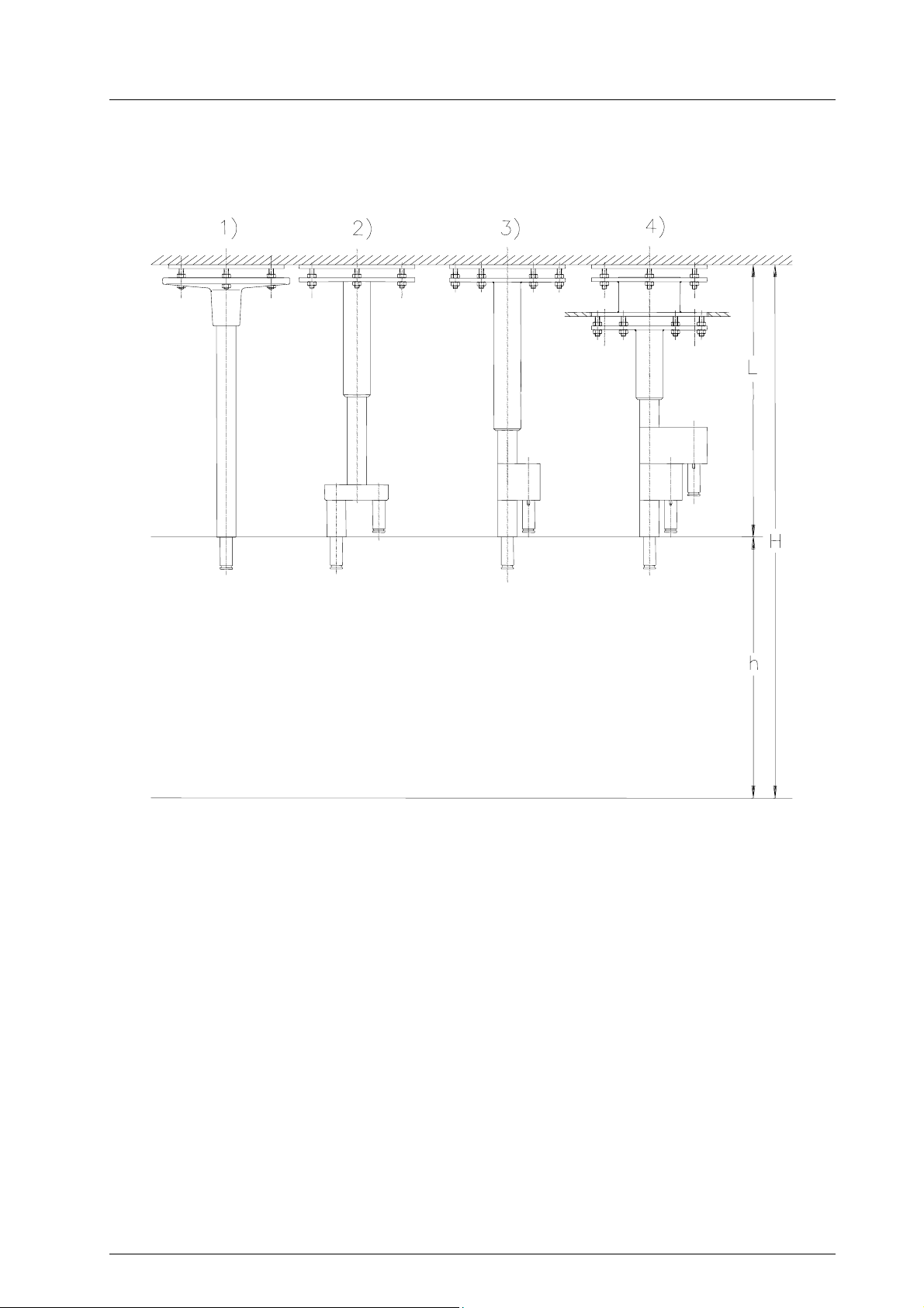
2.2.4 Ceiling attachments and room heights
Dr. Mach
Lamps and Engineering
Ceiling attachments
Featured examples (selection)
1 Single suspension tube with aluminium cast
flange and ceiling anchorage ring
2 Double standard axis with welded flange tube
and ceiling anchorage ring
3 Double light weighted central axis, can be
turned through 360°, with welded flange tube
and ceiling anchorage ring
4 Triple light weighted central axis with welded
flange tube, intermediate flange and ceiling
anchorage ring
H = room height
Clearance upper edge floor – lower edge solid
ceiling
h = prescribed distance upper edge floor to lower
edge suspension tube as specified for the particular lamp
L = length of suspension tube respectively entire
suspension device (ceiling anchorage ring + intermediate flange + suspension tube)
59500001 Edition 06 11.03.2003 / Bak Page 11/48
Ceiling and wall attachment
Dr. Mach
Lamps and Engineering
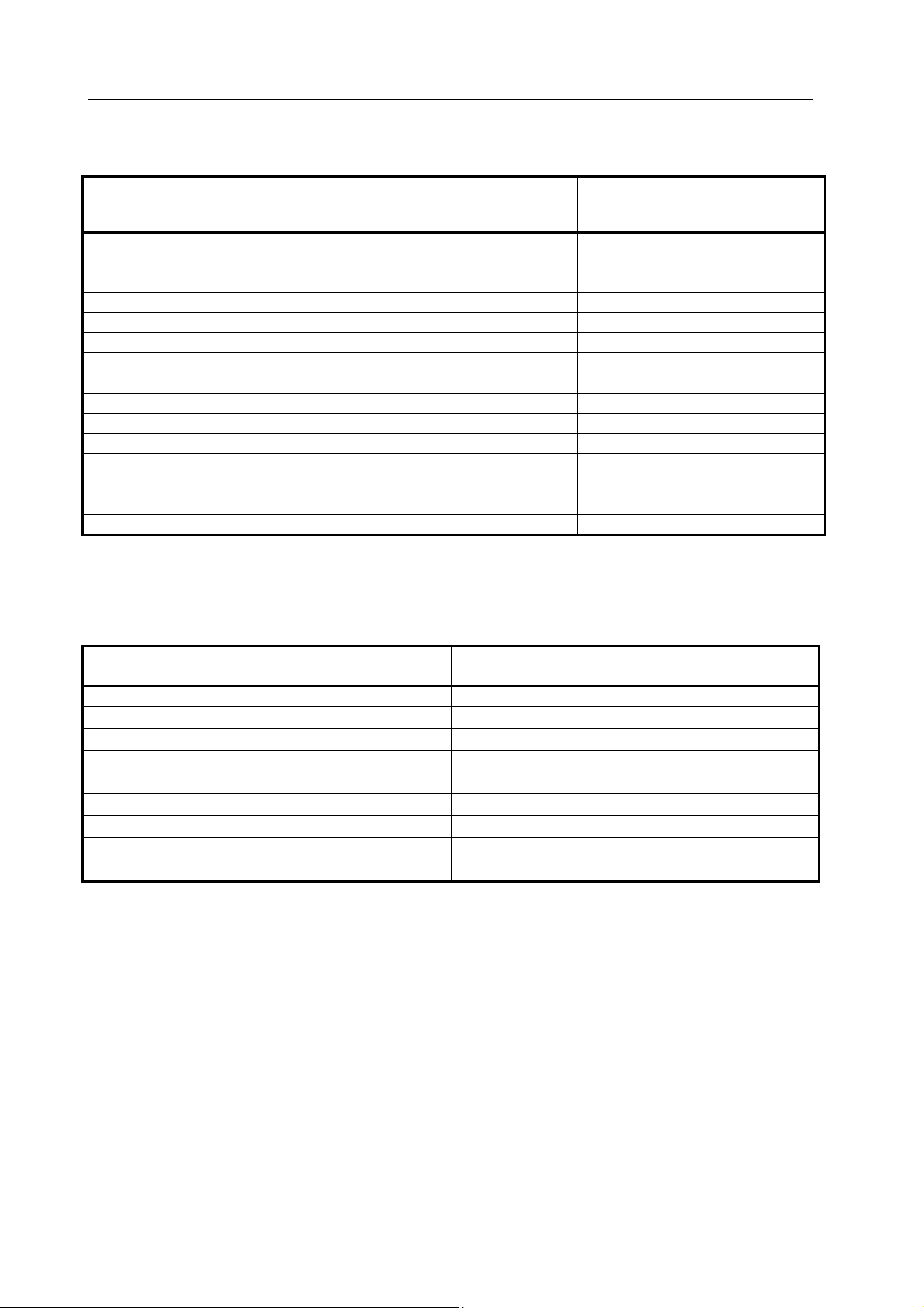
Room heights H single lamps
Hmin*
Lamps
Mach 120 2450 2575
Mach 120F 2450 2575
Soloflex 2450 2570
Soloflex with handle sleeve 2450 2630
Mach 130 2450 2625
Mach 130 -ster. handle sleeve 2450 2625
Triaflex 2450 2580
Triaflex with cardan bow 2450 2630
Trigenflex 2450 2760
Quintaflex 2450 2825
Mach M3 2450 2862
Mach 380 2450 2862
Mach 400 2450 2897
Mach 500 2450 2867
Tool and instrument trays 2450 2680
* Min. room height in the case of ceiling attachment with shortest suspension tube (180mm)
** Min. room height in case of clearance height of 2000mm under the handle of the lamp
depending on
ceiling attachment
Hmin**
depending on
lamp head
Room heights H single lamps – low room height
Lamps
Soloflex with turned joint 2450
Triaflex with turned joint 2450
Trigenflex with fully cardanic joint 2450
Trigenflex with central spring arm 2450
Quintaflex with central spring arm 2450
Mach M3 with central spring arm 2450
Mach 380 with central spring arm 2450
Mach 400 with Space-arm 2520
Mach 500 with Space-arm 2520
* Min. room height in the case of ceiling attachment with shortest suspension tube (180mm)
depending on ceiling attachment
Hmin*
59500001 Edition 06 11.03.2003 / Bak Page 12/48
Ceiling and wall attachment
Dr. Mach
Lamps and Engineering
2.3 Mounting the flange and the suspension tube to the ceiling
Before mounting the flange and the suspension tube, assembly work on the ceiling (setting the dowels or
mounting the ceiling anchorage ring and possibly mounting the intermediate flange) must be completed
and all pre-assembly work finished.
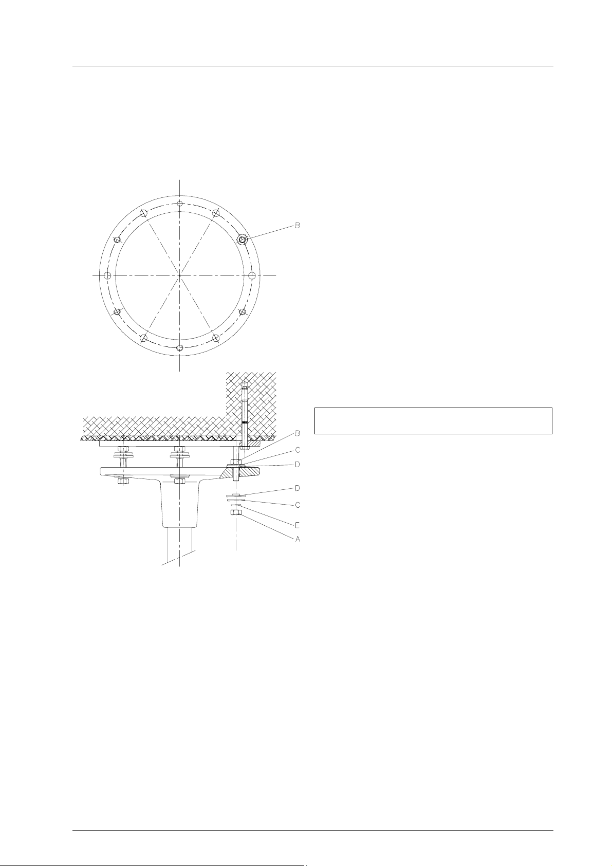
Type with ceiling anchorage ring
• Screw three nuts B (each 120°) to the plate of
the ceiling anchorage ring, holding the other
three nuts 0,5cm away from the plate, unscrew
nuts A.
• Position six washers C and six insulating wash-
ers D on the flange.
• Position the flange with suspension tube on the
threaded bolts and adjust it to the required
height using three nuts A and washers C, insulating washers D, and retaining washers E
(each 120°).
Note: Washers C, insulating washers D and
retaining washers E must be put on the
flange in the same order as shown in the
figure.
• The three-point mounting allows a simple vertical adjustment of the suspension tube.
Vertical adjustment is very important and
must be carried out with great care.
If the flange with suspension tube is not in the correct vertical setting, the support arms of the lamp do
not remain precisely in the proper position, they
could turn away and would therefore require excessive braking.
• Then position from above all six nuts B gently
against the flange.
• Screw on the remaining three nuts A with
washers C, insulating washers D and retaining
washers E and tighten all six nuts equally
cross-wise with a torque wrench (25 Nm).
Note: Washers C, insulating washers D and
retaining washers E must be put on the
flange in the same order as shown in the
figure.
• Verify balance with a spirit-level.
59500001 Edition 06 11.03.2003 / Bak Page 13/48

Ceiling and wall attachment
Dr. Mach
Lamps and Engineering
Type with ceiling anchorage ring and
intermediate flange
• Screw three nuts G (each 120°) to the plate of
the ceiling anchorage ring, the other three 1cm
away from the plate, unscrew nuts F.
• Position the intermediate flange on the
threaded bolts and adjust it to the required
height using three nuts F and washers H.
• Then position all six nuts G gently against the
intermediate flange from above.
• Screw on the remaining three nuts F with
washers H and tighten all six nuts equally
cross-wise with a torque wrench (25 Nm).
• Verify balance with a spirit-level.
For mounting the flange to the intermediate
flange proceed as described at the design with
ceiling anchorage ring.
59500001 Edition 06 11.03.2003 / Bak Page 14/48
Ceiling and wall attachment
3. Mounting layout
Dr. Mach
Lamps and Engineering
Wall attachment
Bracket
Wall bearing
Remark:
One levelling washer is always necessary.
If the distance between wall bracket and spring arm is too big, use the second levelling washer.
The circlip (Seegerring) must be easy to mount and has to snap in. It should turn easily in the groove.
Circlip
Levelling washer (Remark!)
Levelling washer
Spring arm
OT -lamp
59500001 Edition 06 11.03.2003 / Bak Page 15/48

Ceiling and wall attachment
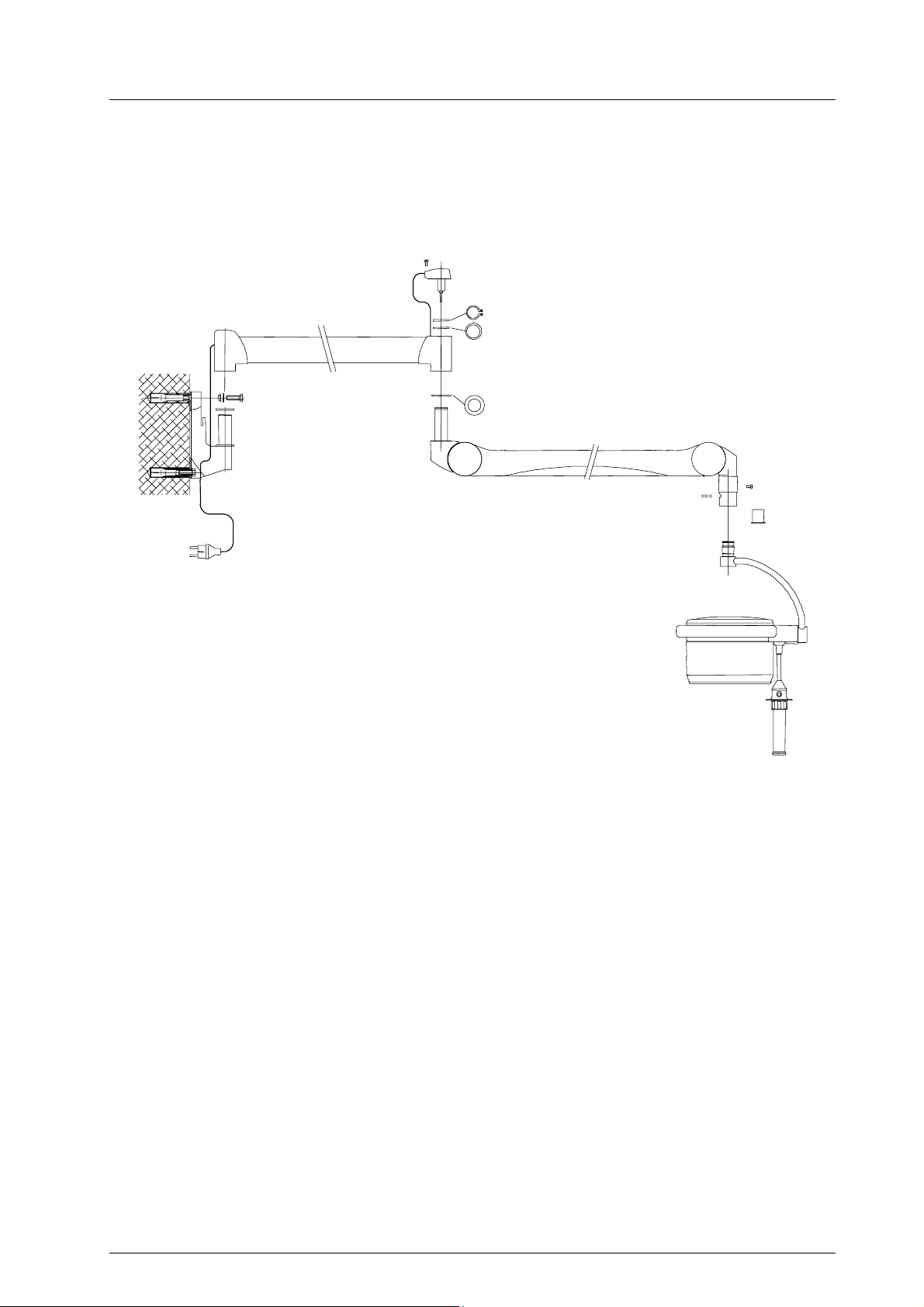
4. Wall attachment
4.1 Preparatory work on the wall
Mounting height
Dr. Mach
Lamps and Engineering
Fastening with tubular dowel
• Using the enclosed template, mark the boreholes at the proper height (depending on the
lamp type) precisely perpendicular.
• Drill or chisel out a hole ∅ 25mm (or slightly
larger) 100mm deep.
• Cement or grout in the tubular dowel flush with
the wall or slightly deeper and let it set well
(keep strictly to the 190mm spacing and perpendicular position).
Fastening with counter-plate
Depending on the stability of the location, it may be
necessary to use a counter-plate for the wall attachment.
• Ascertain the exact position of the OT-lamp-
• In the case of a fixed connection, lay the elec-
trical cable.
• Stick the supplied drilling template to the wall.
• Drill the two holes ∅ 12mm and 190mm apart.
When drilling, keep as closely as possible to the
spacing between the holes. The counter-plate
can be mounted with variations of up to 20mm.
Electrical connection is carried out later using a 2m
long cable provided by Dr. Mach with shock-proof
plug on the wall arm.
It is important to check whether there is an appropriate plug socket in the vicinity.
If the lamp is to be connected directly, the mains
connection must be located between the two fixing
screws (see section showing electrical connection).
Follow any directions given by the technical
staff!
59500001 Edition 06 11.03.2003 / Bak Page 16/48

Ceiling and wall attachment
4.2 Mounting the wall bearing
Dr. Mach
Lamps and Engineering
For mounting the wall bearing proceed as follows:
Fastening with tubular dowel
• Screw tight the wall bearing with two M10x35
screws (having first pushed the washer of
∅ 10mm and the plastic cover washer on the
screw).
• Place cover 1, cover 2 and cap 3 in position in
such a way that they engage in the locks.
Fastening with counter-plate
• Fix the wall bearing, push through the M10
threaded rods and screw on the wall bracket
and counter-plate using bolts and hexagonal
nuts (if necessary, weld the hexagonal nuts to
the counter-plate).
• Place cover 1, cover 2 and cap 3 in position in
such a way that they engage in the locks.
59500001 Edition 06 11.03.2003 / Bak Page 17/48

g
(
)
0
Ceiling and wall attachment
4.2.1 Wall attachment, room heights
70
Wall attachment
400
-50mm tolerance
Dr. Mach
Lamps and Engineering
3
160
lower edge handle sleeve-
upper edge spring arm
2000
X to the lower bore for wall bearin
Room heights H wall attachments
Lower bore for
Lamps
Mach 120 2005 2575 2450
Mach 120F 2005 2575 2450
Soloflex 2000 2570 2450
Soloflex with handle sleeve 2060 2630 2470
Mach 130 2055 2625 2465
Mach 130 –ster. handle sleeve 2055 2625 2465
Triaflex 2010 2580 2450
Triaflex with cardan bow 2060 2630 2470
Trigenflex 2190 2760 2600
Quintaflex 2255 2825 2665
Mach M3 2292 2862 2702
Mach 380 2292 2862 2702
Tool and instrument trays 2110 2680 2480
wall bearing
(min.)
Hmin, so the spring
arm can be adjusted
Hmin for passing
height of at least
2000mm
59500001 Edition 06 11.03.2003 / Bak Page 18/48

Ceiling and wall attachment
4.3 Installing the extension arm stop
1
Dr. Mach
Lamps and Engineering
(surcharge)
Note:
The stop is supplied with a plastic cover with
cut-out.
The upper plastic cover of the wall bearing is no
longer required and may be discarded
• Remove and discard the upper plastic cover 1
of the wall bearing.
4
3
2
• Insert the extension arm stop 2 into the two
grooves 3 of the wall bearing as shown in the
figure.
• Check the extension arm stop 2 for firm seat-
ing.
• Install and engage the supplied plastic cover
with cut-out 4.
• Check the plastic cover with cut-out 4 for firm
seating.
3
• The mounted extension arm stop protects the
lamp from damages caused by accidental touching of the wall.
59500001 Edition 06 11.03.2003 / Bak Page 19/48

Ceiling and wall attachment
Dr. Mach
Lamps and Engineering
5. Electrical connection
5.1 Preparing the electrical connection
Ceiling mounting
Extent of supply
• Cable with special plug
• Line clamps on the flange
Please take note:
• Mark the cables with special plugs on both sides with numbers (only combinations): 1=main
light, 2=satellite lamp 1, 3=satellite lamp 2).
• Mark also the receptacles on the axis (the lowest position with 1, the other positions increasing with 2 and, if present, with 3).
Put the cables with special plug through the flange tube. Ensure that the cables are cut to a length which
allows approx. 15cm cable to extend from the suspension tube.
The flange is fitted with line clamps for connecting the light system to the electrical circuit. These clamps
should be accessible for electrical safety checks during installation and also later.
Connect the mains supply and the cables with special plugs to the line clamp in the right order (plug no.1
to receptacle no.1, etc.).
Wall attachment
The lamp is normally supplied with integrated transformer and connection cable with shock-proof plug
(except Mach 120 and Mach 380). The socket used must be installed according to IEC or VDE 0107 requirements.
The cross-sections of the leads depend on the lead-length and power consumption. Please refer to the
following table:
Power consumption
[W]
up to 10 up to 20 up to 40 up to 70
Lead length [m]
50 2,5 2,5 2,5 4,0
150 2,5 2,5 4,0 6,0
200 2,5 4,0 6,0 10,0
250 2,5 4,0 6,0 10,0
Once the electrical connections have been completed, check that the system functions correctly in a noload operation trial run.
When connecting to an external transformer, the emerging voltage U will be approx. 10-20% above rated
voltage because of no load and anticipated lead losses. There is no point in making any adjustments until
the lamps have been completely mounted.
59500001 Edition 06 11.03.2003 / Bak Page 20/48
Cross-section of lead [mm
2
]
Ceiling and wall attachment
Dr. Mach
Lamps and Engineering
5.2 Electrical connection for lamps with external transformer
Position of transformer – Dr. Mach lamps
Lamps External transformer
Makrolux X*
Miniflex X*
Mach 120 X*
Praxila X X*
Soloflex X X*
Mach 130 / Uniflex X X*
Triaflex X X*
Trigenflex X X*
Quintaflex X*
Mach M3 X*
Mach 380 X*
Mach 400 X*
Mach 500 X*
Mach 700 X*
* Transformer included in extent of supply
Note: In case of lamps with external transformer, the transformer must be mounted separately.
Transformer
in the lamp housing
Transformer mounted in
bracket
For models with electronic transformer- potentiometer instead of
change-over-switch
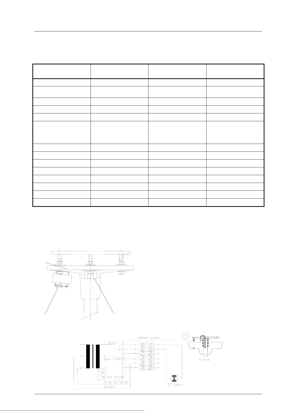
5.2.1 Ceiling lamps with external transformer
a. Single-phase transformer mounted on the flange
View
Flange
Transformer
Wiring
Line clamp
The single-phase transformer is already mounted
on the flange.
At delivery it is already connected to the line clamp.
You have to connect the power supply and the lamp
to the line clamp (see wiring).
Remark
59500001 Edition 06 11.03.2003 / Bak Page 21/48

Ceiling and wall attachment
b. Toroid transformer mounted on the flange
View
Line clamps
Toroid transformer
Flange
Dr. Mach
Lamps and Engineering
The toroid transformer is already mounted on the
flange.
At delivery it is already connected to the line
clamps. You have to connect the power supply and
the lamp to the line clamp (see wiring).
Wiring
5.2.2 Wall lamps with external transformer
a. Lamps Mach 120, Praxila
Wall bearing
Transformer
housing
The transformer is mounted in a transformer housing positioned on the wall.
b. Lamp Mach M3, Mach 380
If possible, You should mount the transformer in a separate room.
If not possible, try to find an appropriate mounting place for the transformer. In case of a false ceiling you
can mount the transformer between false ceiling and solid ceiling.
59500001 Edition 06 11.03.2003 / Bak Page 22/48

Ceiling and wall attachment
Dr. Mach
Lamps and Engineering
5.2.3 Lamps with regulating transformer
The regulating transformer is used for light intensity control at the lamps. It is positioned inside the switch
cabinet / switch board (OT-panel).
Technical data
Type RN 230 / 1.25 Bgr. P40 Type RN 230 / 1.6 Bgr. P65
Primary voltage 230V 230V
Secondary voltage 184 – 230V 0 – 230V
Frequency 50 – 400Hz 50 – 400Hz
Current 1,25A 1,6A
Power 287,5VA 368VA
System of protection IP00 IP00
For mounting the regulating transformer see drilling jigs below:
Type RN 230/1.25 Bgr. P40
Type RN 230/1.6 Bgr. P65
The regulating transformer is connected between mains and lamp transformer.
59500001 Edition 06 11.03.2003 / Bak Page 23/48

Ceiling and wall attachment
5.3 Wiring diagrams
Dr. Mach
Lamps and Engineering
Transformer in the lamp housing
1. Clamps on the flange
2. Coupling with sliding contact on flange
3. Fuses
4. ON/OFF switches
5. Converter
6. Transformer IT
7. Light bulb(s)
External transformer
1. Fuses
2. ON/OFF switch (4-pole for emergency power
connection)
3. Transformer IT
4. Clamps on the flange
5. Coupling with sliding contact on flange
6. Secondary ON/OFF switch
(not for Quintaflex)
7. Light bulb(s)
IT-mains 230V
Green - mai ns
Regulating transformer
to
OT-lamp
59500001 Edition 06 11.03.2003 / Bak Page 24/48

Ceiling and wall attachment
Connecting diagram
Dr. Mach
Lamps and Engineering
6. Mounting the articulated arms
6.1 Ceiling mounting
6.1.1. Mounting the extension arm
Attention!
Disconnect the on-site power supply and protect
it from being switched on again.
• Remove the fastening devices (retaining ring 1,
4
7
6
3
2
tab washer 2 and disk ∅ 38mm 3) from the suspension tube (tool: mounting plier).
• Remove the lateral covering plates of the bracket
as described in chapter 6.1.2.
• Carefully remove the plug 5 from the extension
arm 6 and slide the extension arm onto the single
part extension arm bearing 4.
Attention!
Danger of injury: If the tab washer is missing, the
retaining ring will loosen and the device may fall out
of the mounting and cause serious injury.
Always
• Install the disk ∅ 38mm 3, then insert the tab
• Check the extension arm for firm seating.
install the tab washer.
washer 2 into the hole 7 and install the circlip 1.
1
5
6.1.2 Removing the lateral covering
plates
59500001 Edition 06 11.03.2003 / Bak Page 25/48

Ceiling and wall attachment
Dr. Mach
Lamps and Engineering
• Loosen the two screws S with a cross-head
screw driver.
• Remove the white covering caps AK at the
bracket.
• Remove the subjacent brake screws B with a big
screw driver.
• Spread the two covering plates AS by using a
screw driver.
AS
6.1.3 Electrical connection
Attention!
If the cables at the plug are damaged, the extension arm is under a voltage of 230V.
Install the plug carefully.
6
5
59500001 Edition 06 11.03.2003 / Bak Page 26/48

Ceiling and wall attachment
Dr. Mach
Lamps and Engineering
• Position the plug 5 straight and push it toward the
extension arm 6 using slight pressure.
N
• Push the two noses N of the plug to the inside
with a screw driver, until they snap in.
• Check the plug for firm seating.
• Position and engage the casing halves.
• Screw in the two brakes B and the two screws S
(see chapter 6.1.2).
• Put the two covering caps AK on the brake
screws.
• Check the casing halves for safe fit.
6.2 Wall mounting
Place the upper articulated arm onto the mounted wall bearing on the side of the electrical connection.
In case of a lamp with built in transformer put the plug into the socket.
If the electrical connection is made through the wall (no plug), the power supply cable is connected to the
line clamp in the wall bracket (below cover 1).
Caution: When making the electrical connection, please make sure, that the current is not passing
through the line!
6.3 Mounting the spring arms
6.3.1 Mounting the standard spring arm
12
8
9
6
11
10
Attention!
Disconnect the on-site power supply and protect
it from being switched on again.
• Remove the two lateral covering plates of the
bracket as described in chapter 6.1.2.
• Carefully pull the plug 12 off the bracket.
• Remove the circlip 8, then remove the disk ∅
38mm 9 and the protective sleeve from the
spring arm 10.
• Make sure that the disk ∅ 48mm 11 is installed
to the spring arm.
• Carefully remove the plug 12 from the extension
arm 6.
• Slide the spring arm 10 into the extension arm 6.
• Install the disk ∅ 38mm 9 and install the retaining
ring 8.
• Check the spring arm 10 for firm fixation in the
extension arm 6.
• Establish the electrical connection as described
in chapter 6.3.2 and mount the casing halves.
59500001 Edition 06 11.03.2003 / Bak Page 27/48
Ceiling and wall attachment
12
6
Dr. Mach
Lamps and Engineering
Electrical connection
Attention!
If the cables at the plug are damaged, the extension arm is under a voltage of 230V.
Install the plug carefully.
• Position the plug 12 straight and push it toward
the extension arm 6 using slight pressure.
• Check the plug for firm seating.
Space-spring arm
Mach 500
6.3.2 Mounting the Space spring arm
(
Mach 400 Mach 500, Mach 700 single lamps
at low room heihgts)
The Space –spring arm is intended for installing
lamps as Mach 700 and Mach 500 / Mach 400 in
cases of low room height. The lamp is suspended on
the side of the spring arm.
You still have the necessary free clearance height for
Mach 400 and Mach 500, despite the low room
height. Still, the lights can be moved in the X-axis and
Y-axis.
For mounting the Space –spring arm to the ceiling
attachment proceed as described at chapter 6.3.1.
59500001 Edition 06 11.03.2003 / Bak Page 28/48
Ceiling and wall attachment
Central spring arm
Mach 380
12
8
9
6
11
13
Dr. Mach
Lamps and Engineering
6.3.3 Mounting the central spring arm
(
Mach 380, Mach M3, Quintaflex, Trigenflex
ceiling lamps at low room height)
Central spring arm (since 2000)
The central spring arm is intended for installing lamps
as Mach 380, Quintaflex and Trigenflex in cases of
low room height.
You still have the necessary free clearance height,
despite the low room height. Still, the lights do not
have a fully cardanic suspension anymore.
For mounting the central spring arm to the ceiling
attachment proceed as described at chapter 6.3.1.
Central spring arm (until 2000)
• Disconnect the on-site power-supply.
• Remove the two lateral covering plates of the
bracket as described in chapter 6.1.2.
• Carefully pull the plug 12 off the bracket.
• Remove the circlip 8, then remove the disk ∅
38mm 9 and the protective sleeve from the
spring arm 10.
• Install the disk ∅ 48mm 11 on the spring arm 13.
• Carefully remove the plug 12 from the extension
arm 6.
• Slide the spring arm 13 into the extension arm 6.
• Install the disk ∅ 38mm 9 and install the retaining
ring 8.
• Check the spring arm 13 for firm fixation in the
extension arm 6.
• Establish the electrical connection and mount the
casing halves.
59500001 Edition 06 11.03.2003 / Bak Page 29/48
Ceiling and wall attachment
Dr. Mach
Lamps and Engineering
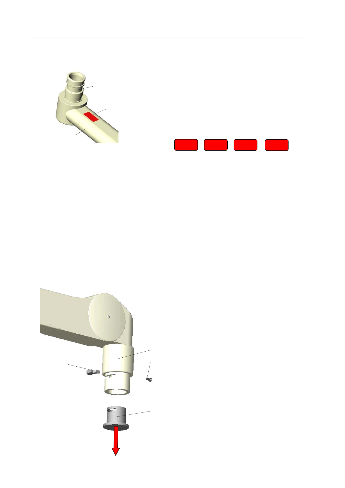
7. Mounting the lamps
Attention!
Each lamp has a red sticker applied near the
Coupling journal
Sticker with voltage
information
Lamp bow or
cardanic bow
When mounting the lamp and also at one-yearly intervals, a light coat of acid-free grease should be applied to the mounting journal and the journal groove F of the lamp, or possibly the already existing cardan
bow.
The lamp may only be dismounted (in reverse order to the mounting procedure) after the mounting safeguard has been positioned and screwed tight, as the arm is under spring tension.
Never let the spring arm bounce up!
7.1 Mounting at the standard spring arm
3
coupling journal at the lamp bow or cardanic
bow. The sticker shows the rated voltage of the
lamp.
Connect the lamp only to the prescribed voltage, to avoid irreparable damage (e.g. the electronical components).
Following rated voltage is usual:
22,8 V
After mounting the lamp take off the sticker and
dispose it, otherwise it could fall down in the
OT-field after some time!
230 V
120 V
Caution:
7.1.1 Preparatory work
Attention!
Disconnect the on-site power supply and protect it from being switched on again.
• Disconnect the equipment / pull out the power
plug and protect the equipment from being
switched on again.
2
Attention!
1
Danger of injury: When it is pressed down, the
spring arm can jump up suddenly and cause
injury.
During the installation of the lamp / device, do
not allow anyone to be within the swivelling
range of the spring arm.
• Remove the recessed head screw 1 and slide
4
the sleeve 2 up.
• Remove the securing segment 3 with a small-
bladed screw driver.
• Remove the protective cap 4 from the mount-
ing.
110 V
59500001 Edition 06 11.03.2003 / Bak Page 30/48

Ceiling and wall attachment
3
2
1
5
Dr. Mach
Lamps and Engineering
7.1.2 Mounting
Attention!
Danger of injury: If an incorrect segment is
used, the lamp / device may fall out of the
mounting and cause serious injury.
Use only original securing segments.
Note:
Maximum lamp / device weight: The lamps /
devices must not exceed the weight of the
mounted spring system. For details about the
spring system please refer to the type plate of
your ACROBAT 2000.
Spring versions:
• 1,0 – 3,5 kg;
• 3,5 – 7,0 kg;
• 7,0 – 12,0 kg;
• 12,0 – 18,0 kg;
• 18,0 – 21,0 kg
• Insert the bow 5 (with grease) into the mount-
ing of the spring arm, insert the securing segment 3 and slide the sleeve 2 down.
• Install the recessed head screw 1.
• Check the bow 5 with the lamp / device for firm
seating in the spring arm.
• Adjust the spring force as described in chapter
8.2.1.
• Adjust the vertical limit as described in chapter
8.3.1.
59500001 Edition 06 11.03.2003 / Bak Page 31/48

Ceiling and wall attachment
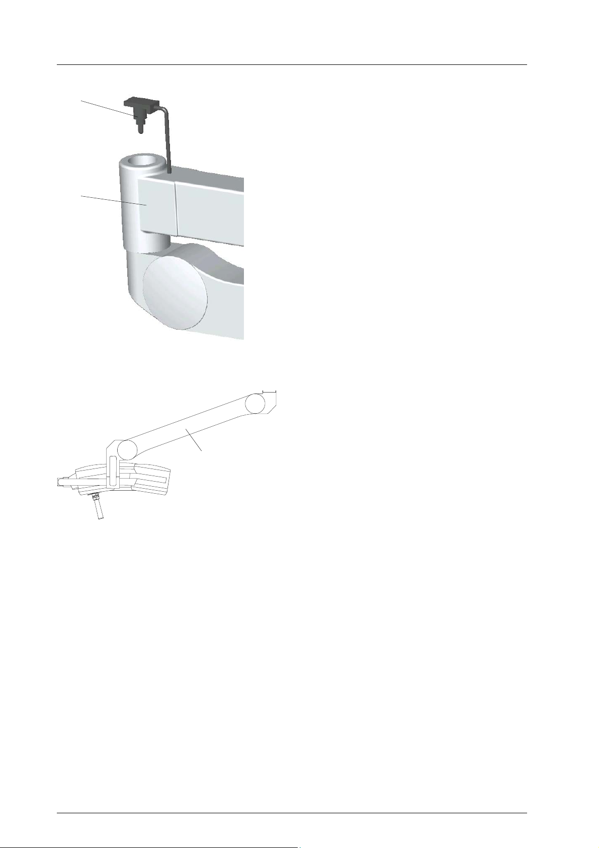
7.2 Mounting at the space spring arm
Top view
3 x screw
Attention: It is not possible to turn the
lamp around this joint (in horizontal
plane) because of its fixing with the
three screws.
1 x segment
Spring arm
105°
Dr. Mach
Lamps and Engineering
To mount a lamp to the space spring arm proceed
as follows:
• Loosen the fixing screw 1 of the retaining
sleeve 2 on the spring arm. Push the sleeve far
enough up for the thread to become visible.
Turn the screw 1 into the thread, so that the
sleeve cannot slip downwards.
• Insert the stud into the spring arm in such a
way that the lamp is in the position illustrated
(see drawing –top view). Secure the lamp with
the segment 3. Fasten the lamp with the
screws 4.
• Fix the retaining sleeve 2 with the screw 1 into
the initial position.
Caution:
Mount the lamp under all circumstances in
the shown position, since the bow could
touch the spring arm while handling the lamp.
Removing the mounting safeguard
The spring arm is locked in the centre position.
In order to permit free movement of the arm,
pull out the locking pin 5 on the side (approx.
1cm).
The lamp body must under all circumstances
be mounted beforehand.
Dismounting the lamp head from the Space
spring arm
Caution:
Before dismounting the lamp, push in the locking pin on the side of the arm.
• Adjust the spring force as described in chapter
8.2.2.
• Adjust the vertical limit as described in chapter
8.3.2.
59500001 Edition 06 11.03.2003 / Bak Page 32/48

Ceiling and wall attachment
7.3 Mounting at the central spring arm
2
3 4
5
2
4
6
5
1
2
1
2
Dr. Mach
Lamps and Engineering
Central spring arm (since 2000)
Preparatory work
Attention!
Power off the on-site power supply and protect
it from being switched on again.
• Power off the pendant system / pull out the
power plug and protect the pendant system
from being switched on again.
Attention!
Danger of injury: The spring arm, when it is
pressed down, can jump up suddenly and cause
injury.
During the installation of the end device, do not
allow anyone to be within the swiveling range of
the spring arm.
• Turn mounting hole 5 in the sleeve 1 down-
wards.
• Remove the brake screw 4 at the bottom side of
sleeve 1.
• Turn sleeve 1 by 90 degrees and remove the
end device securing screw 2.
• Turn sleeve 1 by 180 degrees and remove the
second end device securing screw 2.
• Remove the protective cap 3.
Mounting
Note: Maximum lamp / device weight: The lamps
/ devices must not exceed the weight of the
mounted spring system. For details about the
spring system please refer to the type plate of
your ACROBAT 2000.
Spring version: 10,0 – 15,0 kg
• Insert the end device 6 into the mounting of the
spring arm.
Attention!
Danger of injury: Hold the end device to avoid
its falling down.
• Tighten the first end device securing screw 2.
• Turn sleeve 1 by 180 degrees and tighten the
second end device securing screw 2.
• Turn sleeve 1 by 90 degrees and tighten the
brake screw 4.
• Adjust the brake force so the lamp / the end
device always keeps its set position.
• Check the firm seating of the end device.
• Adjust the spring force as described in chapter
8.2.3.
• Adjust the verrtical limit as described in chapter
8.3.3.
59500001 Edition 06 11.03.2003 / Bak Page 33/48

Ceiling and wall attachment
12
10
13
9
11
7 8
Dr. Mach
Lamps and Engineering
Central spring arm (until 2000)
• Loosen safety screw 7 using a crosshead screw
driver and remove.
• Push safeguard bushing 8 backwards.
• Remove segment 9.
• Slip helmet 10 over the journal of the lamp bow.
• Loosen the two lateral brake screws 11 on the
spring arm using the allen key SW3 (included in
the scope of supply).
• Push the lamp bow into the bore of the spring
arm, such as the journal groove 13 is visible in
slot 12.
• Insert segment 9 and push safeguard bushing 8
forwards, such as the borehole in the safeguard
bushing matches with the thread in the spring
arm.
• Insert safety screw 7 and tighten.
59500001 Edition 06 11.03.2003 / Bak Page 34/48

Ceiling and wall attachment
8. Adjusting the mobility
8.1 Adjusting the mobility at the ceiling suspension
2
Dr. Mach
Lamps and Engineering
Please take note:
• Neither the bracket nor the spring arm may turn
away by themselves.
• Bring the bracket and the spring arm in flat in-
line position. When turning sidewards, the joint
between bracket and spring arm must move
first.
If not, you have to adjust the brake between
bracket and axis.
1
Double light weighted central axis
The position of the brakes (1 and 2) is shown in the
figure.
The brake screws are slotted screws and hexagon
socket screws on the central axis
.
Double standard axis
There are no brakes at the axis.
Slewing capacities of brackets:
• bracket on the lower position – 360°
• bracket on the upper position – 300°
You only have to adjust the brakes 2 between
brackets and spring arms.
300°
360°
59500001 Edition 06 11.03.2003 / Bak Page 35/48

Ceiling and wall attachment
Dr. Mach
Lamps and Engineering
8.2 Adjusting the spring force
The spring arm is correctly adjusted when the lamp remains in position at every set height and can be
moved more easily upwards than downwards.
It is only possible to balance the weight, when the distance between ceiling and bearing journal exceeds
40cm. For low ceilings and consequently short suspension tubes, the drilled nut in the articulated arm
described below, which is required for the balancing procedure, is not visible. The procedure for balancing the weights must in this case be carried out by Dr. Mach or someone authorised by Dr. Mach.
Should you discover, that the light no longer remains at its set height, proceed as follows:
Hole 3
X
4
10°
3
+
-
Width 5
8.2.1 Standard spring arm
Note:
Maximum additional load at spring arms:
Spring arms are equipped with different springs
to compensate the lamp / device weight.
To adjust the spring force make sure that the spring
arm with the lamp / device can come to rest in any
desired position.
• A hole 3 is located at the position marked by
detail X.
• Position the spring arm 4 with the lamp / device
approximately 10° above horizontal.
• Insert Allan key (width 5, included in the scope
of supply) into the hole 3.
If the spring arm drops, the spring force is too
low:
- Rotate the adjustment screw to the left (counter
clockwise) in the + direction.
If the spring arm rises, the spring force is too
high:
- Rotate the adjustment screw to the right
(clockwise) in the - direction.
If the spring arm with the lamp / device cannot
come to rest in any desired position after the
spring force has been adjusted, the springs
must be replaced by a service technician.
59500001 Edition 06 11.03.2003 / Bak Page 36/48

Ceiling and wall attachment
5
Hole 6
6
+
Dr. Mach
Lamps and Engineering
8.2.2 Space spring arm
If you find during use that the lamp does not stay at
the height set, proceed as follows:
N.B.: Only adjust the setting after the locking pin
has been released and the lamp is mounted. Any
course of action other than that described can
cause damage to the arm.
• Remove the protective cover 5 (on the under-side
of the spring arm next to the horizontal arm).
• Insert the allen key (included in the scope of supply).
• Move the arm slightly out of the horizontal position
in a upwards direction until the adjusting screw
-
can be moved easily. It is easiest to adjust the
screw, if you move the arm slightly up and down
in the position found.
You should react as follows to the lamp body movements:
- Lamp moves downwards – turn allen key in
clockwise direction.
- Lamp moves upwards – turn allen key in anti-
clockwise direction.
Store the allen key and replace protective cover 5.
8.2.3 Central spring arm
Central spring arm (since 2000)
To adjust the spring force make sure that the spring
arm with the lamp / device can come to rest in any
desired position.
• Insert the Allan key width 5 in the hole 6.
If the spring arm drops, the spring force is too
low:
- Rotate the adjustment screw to the left (counter
clockwise) in the + direction.
If the spring arm rises, the spring force is too
high:
- Rotate the adjustment screw to the right
(clockwise) in the - direction.
If the spring arm with the lamp / device cannot
come to rest in any desired position after the
spring force has been adjusted, the springs
must be replaced by a service technician.
Width 5
59500001 Edition 06 11.03.2003 / Bak Page 37/48

Ceiling and wall attachment
7
8
2 slots
Dr. Mach
Lamps and Engineering
Central spring arm (until 2000)
• Loosen fixing screw 7 and remove cover 8. You
can see two slots.
• Move the spring arm in a vertical direction, until
the hole nut is visible in one of the slots (eventually in the upper position of the arm).
• Insert the key bolt (included in the scope of
supply) into the hole nut and turn accordingly.
Use only the enclosed key bolt, since a
screw driver could break.
Proceed as follows depending on the movement of
the lamp:
- Lamp moves down on its own – turn bolt in the
direction of the „ + “ mark.
- Lamp moves up on its own – turn bolt in the
direction of the „ - “ mark.
• Fix cover 8 with the screw 7.
Store the enclosed key bolt carefully.
59500001 Edition 06 11.03.2003 / Bak Page 38/48

Ceiling and wall attachment
8.3 Height adjustment
Hole 1
1
Width 5
2
Dr. Mach
Lamps and Engineering
8.3.1 Standard spring arm
The vertical movement of the ACROBAT 2000
spring arm can be limited to 45 degrees above
horizontal.
• A hole 1 is located at the position marked by
detail X.
• Position the spring arm 2 with the end device to
horizontal.
• Insert the Allan key (width 5) into the hole 1.
To reduce the vertical movement:
- Rotate the adjusting screw to the right (clock-
wise).
To increase the vertical movement:
- Rotate the adjusting screw to the left (counter
clockwise).
Remark:
X
In case of stiffness while adjusting the vertical
movement, slightly move the spring arm up and
down.
59500001 Edition 06 11.03.2003 / Bak Page 39/48

Ceiling and wall attachment
X
Y
Dr. Mach
Lamps and Engineering
8.3.2 Space spring arm
The adjustment is carried out as follows:
Dismantle the plastic cover on both sides. Remove
the four screws X, two screws Y on the top side and
another two screws Y on the lower side of the
spring arm and take the two halves apart.
Remove the two inside retaining rings of the stop
pin.
Extract the stop pin and re-insert it in the required
position. Damage can be caused, if the arm is used
without the stop pin.
Affix the two retaining rings. Replace the plastic
cover (four sealing flaps in the guide), engage these
and secure the cover with the eight screws X and Y.
Position Range of movement
a 40° downwards
b 20° downwards
c 40° upwards
d 20° upwards
8.3.3 Central spring arm
Central spring arm (since 2000)
At delivery the spring arm is set in the horizontal
position.
The vertical movement of the spring arm can be
enlarged up to 45 degrees upwards.
Attention!
Power off the on-site power supply and protect
it from being switched on again.
X
3 4
5
• Power off the pendant system / pull out the
power plug and protect the pendant system
from being switched on again.
• Remove the two Philips screws 4 and take off
the covers 3.
• At the position marked X you can see the ad-
justing nut 5.
• Adjust the nut 5 with the enclosed metal pin.
• Mount the two covers 3 and fix them with the
two Philips screws 4.
• Check the firm seating of the covers 3.
59500001 Edition 06 11.03.2003 / Bak Page 40/48

Ceiling and wall attachment
6
-
✚
Dr. Mach
Lamps and Engineering
Central spring arm (until 2000)
• Remove plastic cover 6 at the upper side of the
spring arm. You can see one slot.
• Move the spring arm into a position, in which
the hole nut is visible in the slot.
• Turn the hole nut with the key bolt (included in
the scope of supply) in the direction of the „ + “
mark, until the required height position has
been reached.
Store the enclosed key bolt carefully and fix
plastic cover 6.
Operating instructions
For handling the lamp, please observe the operating instructions supplied by the manufacturer.
9. Maintenance
After mounting the ceiling/wall suspension and the lamps, the brakes between brackets and spring arms
and between brackets and axis (ceiling models) have to be adjusted depending on requirements.
The suspension fixtures have been designed and built, such as regular maintenance intervals are not necessary.
In order to keep the system easy running throughout its life span, we recommend that the hinges should
be greased once a year with an acid-free grease.
Caution: For the yearly maintenance the red safeguard angle G must be inserted and secured using cylinder screw H before the lamp is dismounted.
10. CE –mark
The products comply with the standard 93/42/EEC for medical products of the European
Community’s Council.
59500001 Edition 06 11.03.2003 / Bak Page 41/48

Ceiling and wall attachment
Dr. Mach
Lamps and Engineering
11. Spare parts
4 4
52
(76)
12
11
46
9, 81
28,29
44
64
(78)
15
19
26
74 76
77
76
74
2 (3)
13 (14)
16 (17)
18
(20,21,22), 23
24, 25
30 (31)
35 (36)
32
(76)
43 47
72 70
8
71 72
77
63
9,79,80,81
19
10
33
41 (42)
38 (39)
40
34
44
61
62
63
77
73
76
68,69
65
66
67
64
53
50
51
59500001 Edition 06 11.03.2003 / Bak Page 42/48
54
45
(78)
61
64
72 70
71 72
65
66
67
68,69
Ceiling and wall attachment
Spare parts for central spring arm
Central spring arm (since 2000)
64
(78)
Dr. Mach
Lamps and Engineering
57
72
56
59
60
58
59
67
Central spring arm (until 2000)
106
109
107
108
112
110
113
111
59500001 Edition 06 11.03.2003 / Bak Page 43/48
67
Ceiling and wall attachment
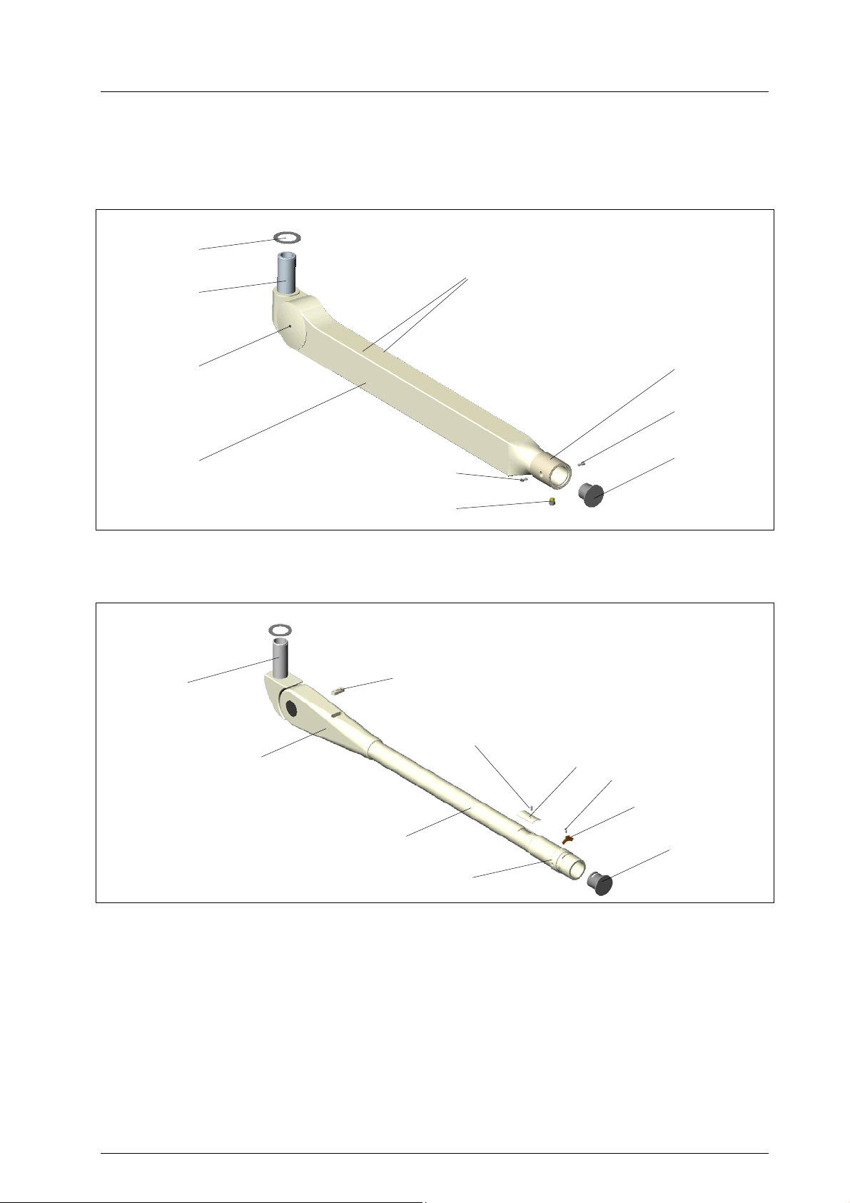
Spare parts for Space spring arm
105
101
67
102,103
104
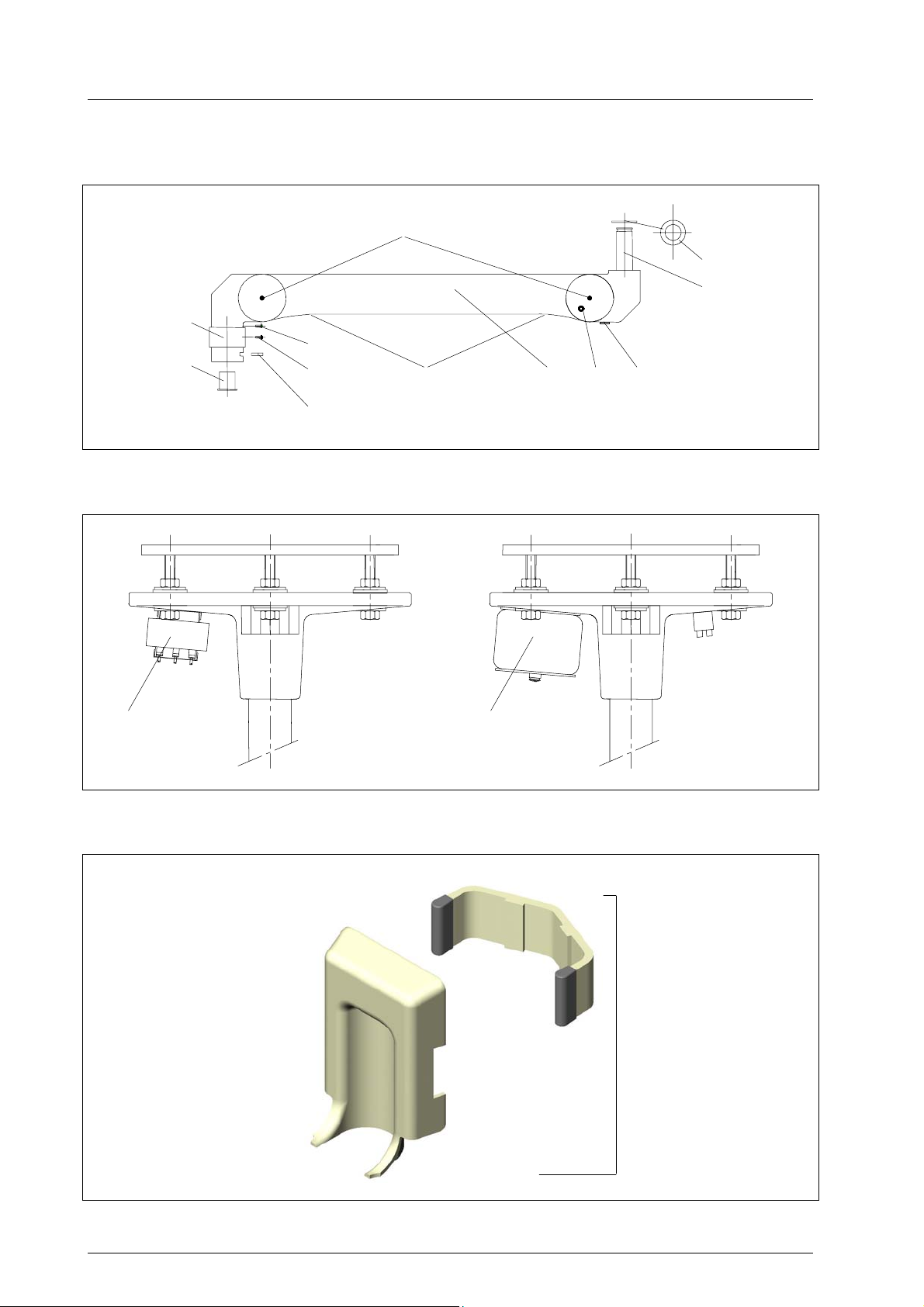
Transformer mounted on the flange
Dr. Mach
Lamps and Engineering
100
64
(78)
99 96 97 98
86,87 88
Spare parts for wall bearing
114
59500001 Edition 06 11.03.2003 / Bak Page 44/48

Ceiling and wall attachment
Dr. Mach
Lamps and Engineering
12. Spare parts list
Item Qty. Name EDVNO Remark
01
02 1 Ceiling anchorage ring TK 270 50480001 alternative
03 1 Ceiling anchorage ring TK 380/270 50480002 alternative
04 6 Safety dowels for ceiling anchorage ring
05
06
07
08 1 Ceiling flange TK 270 50482301
09 12(24) Nut M12 DIN 934-8 galZn 65332023 ( ) with interm. flange
10 1 Safety bolt
11 1 Safety bolt 50753203
12 2 Dummy plug
13 6 Screw M6x16 DIN 933
14 6 Retaining ring B6:A2 DIN 127
15 1 Flange tube TK 270, diameter 70mm 50751001-
50751008
16 1 Canopy 50/450 50222203 alternative
17 1 Divided canopy 50/450 50222208 alternative
18 1 Ring 50mm 50222202
19 1 Cellular rubber seal 1430mm lang 50222209
20 1 Suspension tube 50x4 50221001-
50221028
21 1 Double standard axis 50652001-
50652019
22 1 Light weighted double central axis 50850001 for 360°
23 1 Light weighted triple central axis 50850002 for 360°
24 6 Countersunk screw M6x16 DIN 7991 galZN 65162006
25 6 Cover (white)
26 1 Canopy 70/450 50753204 alternative
27 1 Divided canopy 70/450 50753206
28 1 Ring 70mm 50754201
29 1 Special ring 70/50 with washer 50754001 Not shown
30 1 Triple bracket 50850204
31 1 Double bracket 50850203 Not shown
32 1 Intermediate bushing for double turn 50850215
33 1 Sliding contact set 50852001 Triple version: 2 each
34 1 Coupling journal 50851201 Triple version: 2 each
35 1
36 1
37
38 1 Cover for triple bracket 50850208 Not shown
39 1 Cover for double bracket 50850207
40 2 Countersunk screw M2,5x5 DIN 963 65082035
41 1 Safety plate for triple bracket 50850206 Not shown
42 1 Safety plate for double bracket 50850205
43 1,2,3 Ceiling bracket 750mm – standard
44 2 Adjusting screw for brake
45 1 Wall bracket 750mm – standard
46 2 Cover for wall bracket
47
48
Triple suspension for turning through 360° complete
Double suspension for turning through 360° complete
50850002
50850001 Not shown
Suspension tube ∅50
Flange tube ∅70
single
double
600mm – option
950mm – option
600mm – option
950mm – option
59500001 Edition 06 11.03.2003 / Bak Page 45/48

Ceiling and wall attachment
Dr. Mach
Lamps and Engineering
Spare parts list
Item Qty. Name EDVNO Remark
49
50 1 Wall bearing 74841001 complete
51 1 Attachment set for wall bearing 74841002
52 1 Cover for wall bearing 74841003
53 1 Cover for wall bearing 74841004
54 1 Cap 74841005
55
56 1 Central spring arm Acrobat 2000
57 2 Cover for central spring arm
58 1 Sliding sleeve
59 2 Safety screw for central spring arm
60 1 Brake screw for central spring arm
61 2 Levelling washer 74011012
62 1 Gib washer 74011013
63 1 Circlip 74011014
64 2 Levelling washer 74011012
65 1 Sliding sleeve for semi-circular spring 53070208
66 1 Semi-circular spring 74011001
67 1 Helmet
68 1 Safety screw M4x10 DIN 7985 65152035
69 1 Serrated lock washer A4,3 DIN 6798 65592008
70 1 Standard spring arm Acrobat 2000
71 2 Cover for spring arm
72 4 (2) Fixing screw for cover
73
74 1 Cover
75
76 1 (2) Sliding contact complete with cabling 50223001
...28
77 2 Sliding contact plug 67330002 Wall arm one only
78 2 Sliding contact sleeve 67330001 Wall arm one only
79 12 Washer 13 DIN 9021 galZn 65272001
80 12 Insulating washer 50281222
81 6(12) Retaining washer SK12 galZn ( ) with interm. flange
82
83
84
85
86 1 Transformer 40VA 67010205 Mach 120; Praxila ceiling
87 1 Transformer 120VA 67010202 Triaflex ceiling model
88 1 Toroid transformer 200VA
300VA
89 1 Electronic transformer 50VA (not shown) 67010401 Mach 120 wall model
90 1 Canopy 50/420; height 110mm 50222207 Not shown
91 Flat canopy 50/450; height 60mm Not shown
92 Cylindric canopy 50/400; height 225mm
for camera
93 Divided covering plate 50/450; 2mm thick 50281225 Not shown
95 Cylindric canopy 50/400; height 170mm
for camera
67010208
Not shown
Not shown
Ceiling tube – 1 piece
Standard axis 2 arms– 2
pieces
Light-weighted central
axis 2 arms – 2 pieces
/ wall models
Trigenflex, Quintaflex,
Mach M3/380/400/500
ceiling models
59500001 Edition 06 11.03.2003 / Bak Page 46/48

Ceiling and wall attachment
Dr. Mach
Lamps and Engineering
Spare parts list
Item Qty. Name EDVNO Remark
96 1 Space spring arm 74804001
74804002
97 1 Stop pin
98 1 Covering cap
99 2+8 Cover, 2-parted with screw M3x6 ULF 74012026
100 4 Screw M4x8 DIN 966
101 1 Screw M4x25 DIN 966 65112012
102 3 Screw M4x10 DIN 912 65052017
103 3 Serrated lock washer A4,3 DIN 6798 65592008
104 1 Semi-circular spring 74011001
105 1 Sliding sleeve for semi-circular spring 53070208
106 1 Cover for height adjustment until 2000
107 2 Cover 74012025 until 2000
108 1 Cover for spring force adjustment until 2000
109 1 Screw for pos. 108 until 2000
110 1 Sem-circular spring 74011001 until 2000
111 1 Sliding sleeve for semi-circular spring 53070208 until 2000
112 1 Securing screw M4x10 DIN 7985 65152035 until 2000
113 1 Central spring arm 74803002 until 2000
114 1 Extension arm stop for wall lamps incl. upper plas-
tic cover with cut-out
74829005 surcharge
59500001 Edition 06 11.03.2003 / Bak Page 47/48

Ceiling and wall attachment
Dr. Mach
Lamps and Engineering
59500001 Edition 06 11.03.2003 / Bak Page 48/48
 Loading...