

Page 1
DM 2610934164 05-06 10/6/06 8:41 AM Page 1
400 Series Digital
High Speed Rotary Tool
Operating/Safety Instructions
Model 398-49
HONESTLY NOW … Have you read
this OWNER’S MANUAL?
• Safety
• Assembly
• Operation
• Maintenance
• Accessory Information
• Warranty
• Service Parts
03-5415317
http://www.dremel.com
Dremel brand products are manufactured and sold by the
Dremel Division of Robert Bosch T
2610934164 10/06 Printed in Mexico
ool Corporation
This symbol refers to
the EMC requirements
of the Australian
Standards
Page 2

DM 2610934164 05-06 10/6/06 8:41 AM Page 2
Power Tool Safety Rules
WARNING
!
Read and understand all instructions. Failure to follow all instructions listed below, may
result in electric shock, fire and/or serious personal injury.
SAVE THESE INSTRUCTIONS
Work Area
Keep your work area clean and well lit. Cluttered
benches and dark areas invite accidents.
Do not operate power tools in explosive
atmospheres, such as in the presence of flammable
liquids, gases, or dust.
which may ignite the dust or fumes.
Keep by-standers, children, and visitors away while
operating a power tool. Distractions can cause you
to lose control.
Power tools create sparks
Electrical Safety
Double Insulated tools are equipped with a polarized
plug (one blade is wider than the other.) This plug
will fit in a polarized outlet only one way. If the plug
does not fit fully in the outlet, reverse the plug. If it
still does not fit, contact a qualified electrician to
install a polarized outlet. Do not change the plug in
any way.
the three wire grounded power cord and grounded
power supply system. Before plugging in the tool, be
certain the outlet voltage supplied is within the voltage
marked on the nameplate. Do not use “AC only” rated
tools with a DC power supply.
Avoid body contact with grounded surfaces such as
pipes, radiators, ranges and refrigerators. There is
an increased risk of electric shock if your body is
grounded. If operating the power tool in damp
locations is unavoidable, a Ground Fault Circuit
Interrupter must be used to supply the power to your
tool. Electrician’s rubber gloves and footwear will
further enhance your personal safety.
Don't expose power tools to rain or wet conditions.
Water entering a power tool will increase the risk of
electric shock.
Do not abuse the cord. Never use the cord to carr
the tools or pull the plug from an outlet. Keep cord
away from heat, oil, sharp edges or moving parts.
Replace damaged cords immediately.
cords increase the risk of electric shock.
When operating a power tool outside, use an
outdoor extension cord marked "W
cords are rated for outdoor use and reduce the risk of
electric shock. Refer to “Recommended sizes of
Extension Cords” in the Accessory section of this
manual.
Double Insulation eliminates the need for
Damaged
."
-A" or "W
These
Personal Safety
Stay alert, watch what you are doing and use
common sense when operating a power tool. Do not
use tool while tired or under the influence of drugs,
alcohol, or medication.
while operating power tools may result in serious
personal injury.
Dress properly. Do not wear loose clothing or
jewelry. Contain long hair. Keep your hair, clothing,
and gloves away from moving parts. Loose clothes,
jewelry, or long hair can be caught in moving parts.
Keep handles dry, clean and free from oil and grease.
Avoid accidental starting. Be sure switch is “OFF”
before plugging in. Carrying tools with your finger on
the switch or plugging in tools that have the switch
“ON” invites accidents.
Remove adjusting keys or wrenches before turning
the tool “ON”. A wrench or a key that is left attached
to a rotating part of the tool may result in personal
injury.
Do not overreach. Keep proper footing and balance
at all times. Proper footing and balance enables
better control of the tool in unexpected situations.
Use safety equipment. Always wear eye protection.
Dust mask, non-skid safety shoes, hard hat, or
hearing protection must be used for appropriate
conditions.
A moment of inattention
Tool Use and Care
Use clamps or other practical way to secure and
support the workpiece to a stable platform. Holding
the work by hand or against your body is unstable
and may lead to loss of control.
Do not force tool. Use the correct tool for your
application.
y
safer at the rate for which it is designed.
Do not use tool if switch does not turn it “ON” or
“OFF”.
switch is dangerous and must be repaired.
Disconnect the plug from the power source before
making any adjustments, changing accessories, or
storing the tool.
reduce the risk of starting the tool accidentally.
Store idle tools out of reach of children and other
untrained persons. Tools are dangerous in the hands
of untrained users.
Page 2
The correct tool will do the job better and
Any tool that cannot be controlled with the
Such preventive safety measures
Page 3

DM 2610934164 05-06 10/6/06 8:41 AM Page 3
Maintain tools with care. Keep cutting tools sharp
and clean. Properly maintained tools, with sharp
utting edges are less likely to bind and are easier to
c
control. Any alteration or modification is a misuse and
may result in a dangerous condition.
Check for misalignment or binding of moving parts,
breakage of parts, and any other condition that may
affect the tools operation. If damaged, have the tool
serviced before using.
poorly maintained tools. Develop a periodic
maintenance schedule for your tool.
Use only accessories that are recommended by the
manufacturer for your model. Accessories that may
be suitable for one tool, may become hazardous when
used on another tool.
Many accidents are caused by
Safety Rules for Rotary Tools
Accessories must be rated for at least the speed
recommended on the tool warning label.
and other accessories running over rated speed can
fly apart and cause injury.
Hold tool by insulated gripping surfaces when
performing an operation where the cutting tool may
contact hidden wiring or its own cord. Contact with
a "live" wire will make exposed metal parts of the tool
"live" and shock the operator. If cutting into existing
walls or other blind areas where electrical wiring may
exist is unavoidable, disconnect all fuses or circuit
breakers feeding this worksite.
Do not operate the flexible shaft with a sharp bend.
Over bending the shaft can generate excessive heat
on the jacket or hand piece. The recommended
minimum is 13cm radius.
Always disconnect the power cord from the power
source before making any adjustments or attaching
any accessories. You may unexpectedly cause the
tool to start leading to serious personal injury.
Be aware of the switch location, when placing the
tool down or when picking the tool up.
accidentally activate the switch.
Always hold the hand piece firmly in your hands
during the start-up. The reaction torque of the motor,
as it accelerates to full speed, can cause the shaft to
twist.
Always wear safety goggles and dust mask. Use
only in well ventilated area.
devices and working in safe environment reduces risk
of injury.
Using personal safety
Wheels
You may
Service
Tool service must be performed only by qualified
repair personnel.
by unqualified personnel could result in a risk of
injury. For example: internal wires may be misplaced
or pinched, safety guard return springs may be
improperly mounted.
When servicing a tool, use only identical
replacement parts. Follow instructions in the
Maintenance section of this manual. Use of
unauthorized parts or failure to follow Maintenance
Instructions may create a risk of electric shock or
injury. Certain cleaning agents such as gasoline,
carbon tetrachloride, ammonia, etc. may damage
plastic parts.
After changing the bits or making any adjustments,
make sure the collet nut and any other adjustment
devices are securely tightened. Loose adjustment
device can unexpectedly shift, causing loss of control,
loose rotating components will be violently thrown.
Do not reach in the area of the spinning bit. The
proximity of the spinning bit to your hand may not
always be obvious.
Allow brushes to run at operating speed for at least
one minute before using wheel. During this time no
one is to stand in front or in line with the brush.
Loose bristles or wires will be discharged during the
run-in time.
Wire and bristle brushes must never be operated at
speeds greater than 15.000/min. Direct the
discharge of the spinning wire brush away from
you. Small particles and tiny wire fragments may be
discharged at high velocity during the “cleaning”
action with these brushes and may become imbedded
in your skin. Bristles or wires will be discharged from
the brush at high speeds.
Wear protective gloves and face shield with wire or
bristle brushes. Apply wire or bristle brushes lightly
to the work as only the tips of the wire/bristles do
the work. “Heavy” pressure on bristles will cause the
wire or bristle to become overstressed, resulting in a
wiping action and will cause the bristles/wire to be
discharged.
Carefully handle both the tool and individual
grinding wheels to avoid chipping or cracking.
Install a new wheel if tool is dropped while
Service or maintenance performed
Page 3
Page 4
DM 2610934164 05-06 10/6/06 8:41 AM Page 4
Safety Rules for Rotary Tools - (cont.)
grinding. Do not use a wheel that may be damaged.
Fragments from a wheel that bursts during operation
will fly away at great velocity possibly striking you or
bystanders.
Never use dull or damaged bits. Sharp bits must be
handled with care. Damaged bits can snap during
use. Dull bits require more force to push the tool,
possibly causing the bit to break.
Use clamps to support workpiece whenever
practical. Never hold a small workpiece in one hand
and the tool in the other hand while in use. Allow
for sufficient space, at least 15,2cm, between your
hand and the spinning bit. Round material such as
dowel rods, pipes or tubing have a tendency to roll
while being cut, and may cause the bit to “bite” or
jump toward you. Clamping a small workpiece allows
you to use both hands to control the tool.
Inspect your workpiece before cutting. When cutting
irregularly shaped workpieces, plan your work so it
will not slip and pinch the bit and be torn from your
hand. For example, if carving wood, make sure there
are no nails or foreign objects in the workpiece. Nails
or foreign objects can cause the bit to jump.
Never start the tool when the bit is engaged in the
material. The bit cutting edge may grab the material
causing loss of control of the cutter.
Avoid bouncing and snagging the wheel, especially
when working corners, sharp edges etc.
cause loss of control and kick-back.
The direction of feed with the bit into the material
when carving, routing or cutting is very important.
Always feed the bit into the material in the same
direction as the cutting edge is exiting from the
material (which is the same direction as the chips
are thrown). Feeding the tool in the wrong direction,
causes the cutting edge of the bit to climb out of the
work and pull the tool in the direction of this feed.
If the workpiece or bit becomes jammed or bogged
down, turn the tool “OFF” by the switch. Wait for
all moving parts to stop and unplug the tool, then
work to free the jammed material. If the switch to
the tool is left “ON” the tool could restart
unexpectedly causing serious personal injury.
Do not leave a running tool unattended, turn power
off. Only when tool comes to a complete stop it is
safe to put it down.
Do not grind or sand near flammable materials.
Sparks from the wheel could ignite these materials.
This can
Do not touch the bit or collet after use. After use the
bit and collet are too hot to be touched by bare hands.
Regularly clean the tool's air vents by compressed
air. Excessive accumulation of powdered metal inside
the motor housing may cause electrical failures.
Do not allow familiarity gained from frequent use of
your rotary tool to become commonplace. Always
remember that a careless fraction of a second is
sufficient to inflict severe injury.
Do not alter or misuse tool. Any alteration or
modification is a misuse and may result in serious
personal injury.
This product is not intended for use as a dental
drill, in human or veterinary medical applications.
Serious personal injury may result.
When using the steel saws, cutoff wheels, high
speed cutters or tungsten carbide cutters, always
have the work securely clamped. Never attempt to
hold the work with one hand while using any of
these accessories. The reason is that these wheels
will grab if they become slightly canted in the groove,
and can kickback causing loss of control resulting in
serious injury. Your second hand should be used to
steady and guide the hand holding the tool. When a
cutoff wheel grabs, the wheel itself usually breaks.
When the steel saw, high speed cutters or tungsten
carbide cutter grab, it may jump from the groove and
you could lose control of the tool.
WARNING
!
drilling, and other construction activities contains
chemicals known to cause cancer, birth defects or
other reproductive harm. Some examples of these
chemicals are:
• Lead from lead-based paints,
• Crystalline silica from bricks and cement and other
masonry products, and
• Arsenic and chromium from chemically treated
lumber.
Your risk from these exposures varies, depending on
how often you do this type of work. To reduce your
exposure to these chemicals: work in a well ventilated
area, and work with approved safety equipment, such
as those dust masks that are specially designed to
filter out microscopic particles.
Some dust created by power
sanding, sawing, grinding,
Page 4
Page 5
DM 2610934164 05-06 10/6/06 8:41 AM Page 5
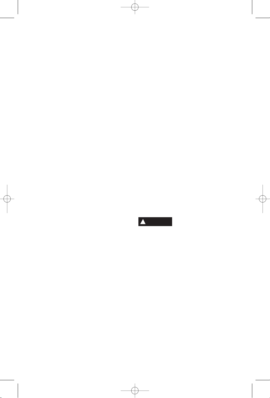
Functional Description and Specifications
WARNING
!
tool accidentally.
COLLET NUT
COLLET
Disconnect the plug from the power source before making any assembly, adjustments
or changing accessories. Such preventive safety measures reduce the risk of starting the
Rotary Tool
FIG. 1
SWITCH
SHAFT LOCK
BUTTON
VENTILATION
OPENINGS
Model number 398-49
Voltage rating 230-240 V , 50-60 Hz
Power rating 140W
No load speed n05.000-33.000/min
Collet capacities 0,8mm, 1,6mm, 2,4mm, 3,2mm
COLLET
SPEED
DOWN
BUTTON
FLEXIBLE
SHAFT
CORE
L.C.D.
DISPLAY
SPEED UP
BUTTON
HANGER
CORD
DRIVER
CAP
COLLET NUT
(NOT INCLUDED)
WRENCH
Page 5
Page 6
DM 2610934164 05-06 10/6/06 8:41 AM Page 6
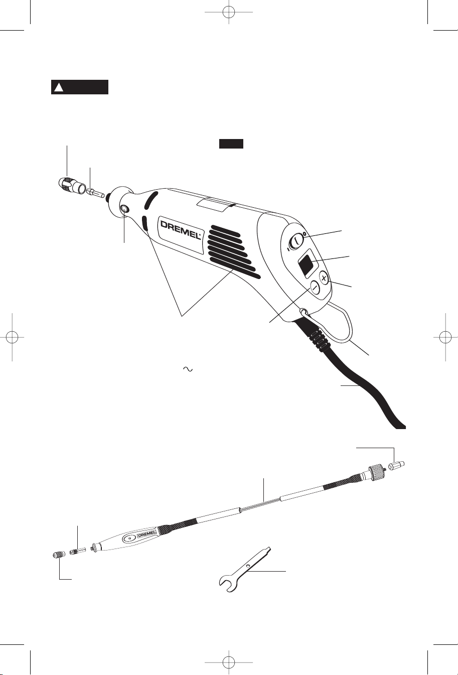
Assembly
!
WARNING
collets or servicing your Rotary Tool.
S
COLLET
WRENCH
Always unplug Rotary Tool before
changing accessories, changing
HAFT LOCK
BUTTON
TO TIGHTEN
TO LOOSEN
COLLET
NUT
COLLET
COLLET
To loosen, first press shaft lock button and rotate the
shaft by hand until the lock engages the shaft
preventing further rotation.
!
CAUTION
With the shaft lock engaged use the collet wrench to
loosen the collet nut if necessary. Change accessories
by inserting the new one into the collet as far as
possible to minimize runout and unbalance. With the
shaft lock engaged, finger tighten the collet nut until the
accessory shank is gripped by the collet. Avoid
excessive tightening of the collet nut.
Do not engage lock while the
Rotary Tool is running.
COLLETS
Four different size collets (see illustration), to
accommodate different shank sizes, are available for
your Rotary Tool. To install a different collet, remove the
collet nut and remove the old collet. Insert the unslotted
end of the collet in the hole in the end of the tool shaft.
Replace collet nut on the shaft. Always use the collet
which matches the shank size of the accessory you
plan to use. Never force a larger diameter shank into a
collet.
BALANCING ACCESSORIES
For precision work, it is important that all accessories
be in good balance (much the same as the tires on your
automobile). T
loosen collet nut and give the accessory or collet a 1/4
turn. Retighten collet nut and run the Rotary Tool. You
should be able to tell by the sound and feel if your
accessory is running in balance. Continue adjusting in
this fashion until best balance is achieved. To maintain
balance on abrasive wheel points, before each use, with
o true up or balance an accessor
y, slightly
COLLET IDENTIFICATION CHART — Collet sizes can
be identified by the rings on the back end of collet.
0,8mm Collet has one (1) ring.
1,6mm Collet has two (2) rings.
2,4mm Collet has three (3) rings.
3,2mm Collet has no rings.
COLLET
NUT
IDENTIFICATION
RINGS
480
3,2mm
COLLET
the wheel point secured in the collet, turn on the Rotary
Tool and run the 415 Dressing Stone lightly against the
revolving wheel point. This removes high spots and
trues up the wheel point for good balance.
The hanger is provided for the use of hanging your
tool while using the flex-shaft or for storage. If you do
not use the hanger, remove it from the tool and snap
it back into place underneath the cord so it will be out
of the way while the tool is in use.
481
2,4mm
COLLET
482
1,6mm
COLLET
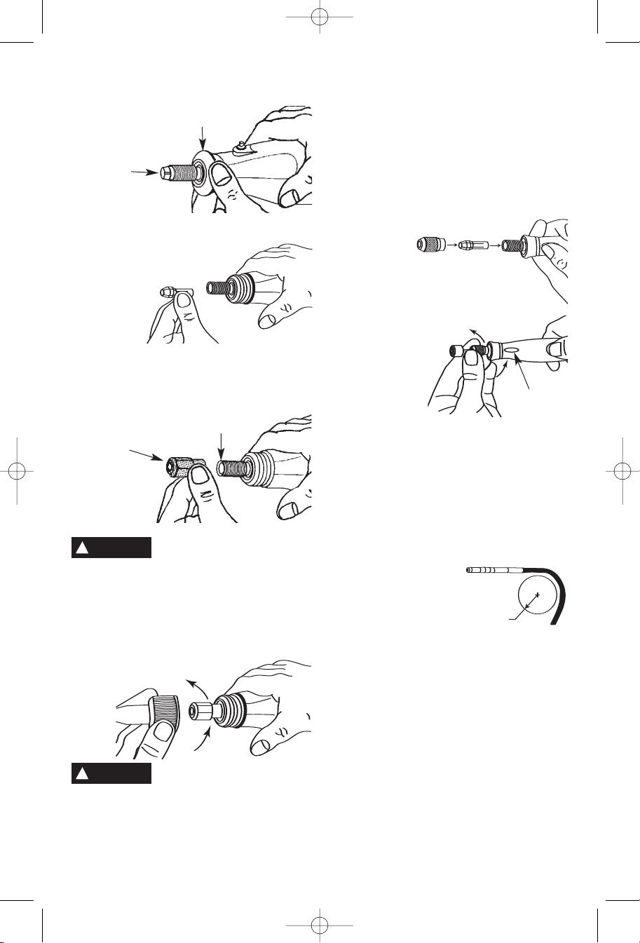
FLEX-SHAFT TO ROTARY TOOL INSTALLATION
To properly attach the flex-shaft to the rotary tool,
THREE items must be removed from the tool: the
housing cap, collet nut and collet.
Step 1. Press the Shaft lock button, unscrew and
remove the collet nut.
Step 2. Unscrew the housing cap from the tool.
Page 6
483
0,8mm
COLLET
Page 7
DM 2610934164 05-06 10/6/06 8:41 AM Page 7
Assembly - (cont.)
OUSING
H
AP
C
OLLET
C
inside)
(
Step 3. Remove the collet.
Note: If the collet nut and collet are not removed from
the motor shaft, the tool will not function properly.
Step 4. Install the driver cap on the motor shaft and
tighten.
MOTOR
SHAFT
DRIVER
CAP
!
CAUTION
the driver cap finger tight and then tighten an
additional 1/3 turn with the wrench. (Wrench included
with your rotary tool kit)
Step 5. Attach by screwing the collar of the flex-shaft
to the rotary tool. Make sure the square end of the
center core engages the square hole socket in the
driver cap.
!
CAUTION
could cause disengagement of center core from
handpiece. If tool stops when shaft is bent, center
core may be lodged in driver cap. Loosen shaft and
remove core from driver cap. Then screw flexible
shaft onto rotary tool housing again.
To prevent damage to tool, do not
overtighten driver cap. Tighten
Do not pull out center core to
engage into driver cap. This
Disengagement of the Flex-Shaft
The flexible shaft may become disengaged if the
motor of your rotary tool is not elevated higher than
the working end of the flex-shaft. The #2222 Rotary
Tool Stand is recommended to hold the rotary tool at
the proper height.
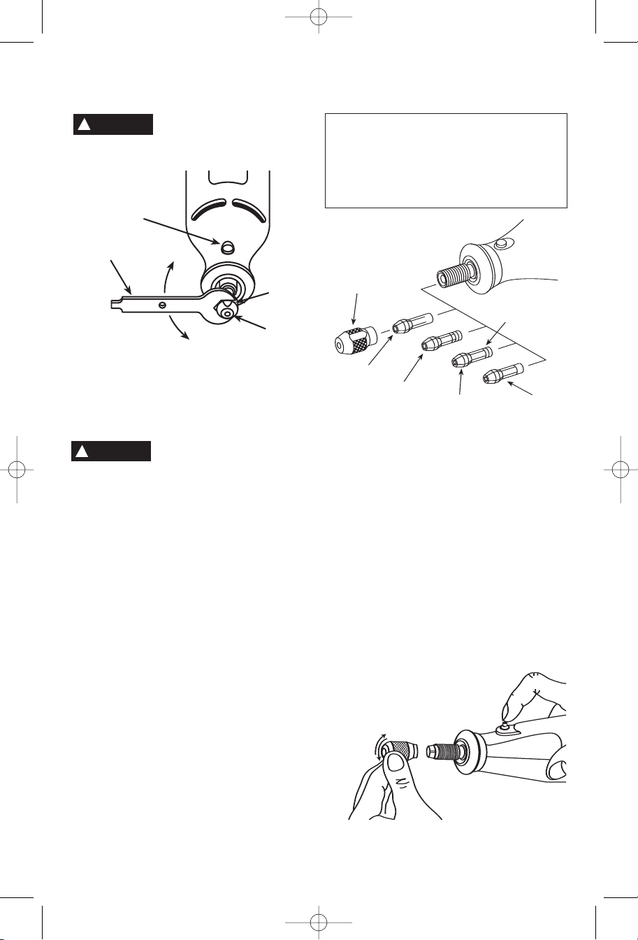
Collet and Accessory Assembly
The collet assembly consists of a collet nut and collet.
Take the collet nut
and collet that
were removed
from your tool in
step 2 and 3 and
insert them into
the tip of the flexshaft handpiece.
Insert an accessory or
bit as deeply as
possible to avoid
wobble during use.
With the shaft lock
button engaged on the
flex-shaft handpiece
retighten the collet nut.
Collet Removal and Replacement
Four different size collets to accommodate different
shank sizes, are sold separately for your flex-shaft. To
install a different collet, remove the collet nut and
remove the old collet. Insert the unslotted end of the
collet in the hole in the end of the flex-shaft. Replace
collet nut on the shaft. Always use the collet which
matches the shank size of the accessory you plan to
use. Never force a larger diameter shank into a
collet.
Do not operate the
flexible shaft with a
sharp or multiple
bends. Over bending
the shaft can generate
excessive heat on the
jacket or hand piece
and may cause the flexible shaft to disengage from
tool. The minimum recommended bend radius is 13cm.
Flexible Shaft Lubrication
The flex-shaft should be lubricated after every 25-30
hours of use. To lubricate, unscrew the flex-shaft
assembly from the motor housing. Pull the center
core out of the flex-shaft assembly. Wipe a very thin
film automotive wheel bearing grease on to the center
core and reinsert it back into the shaft. To prevent
damage to tool do not over grease shaft. Too much
grease will cause the unit to overheat.
Reattach the flex-shaft to the rotary tool.
Contents of 225 Flex-Shaft Attachment
Qty. Description
1 Flex-Shaft Assembly (1,07m long)
1 Driver Cap
Page 7
13CM
RADIUS
SHAFT LOCK
BUTTON
Page 8
3
/4
1
/2
1
/4
0
DM 2610934164 05-06 10/6/06 8:41 AM Page 8
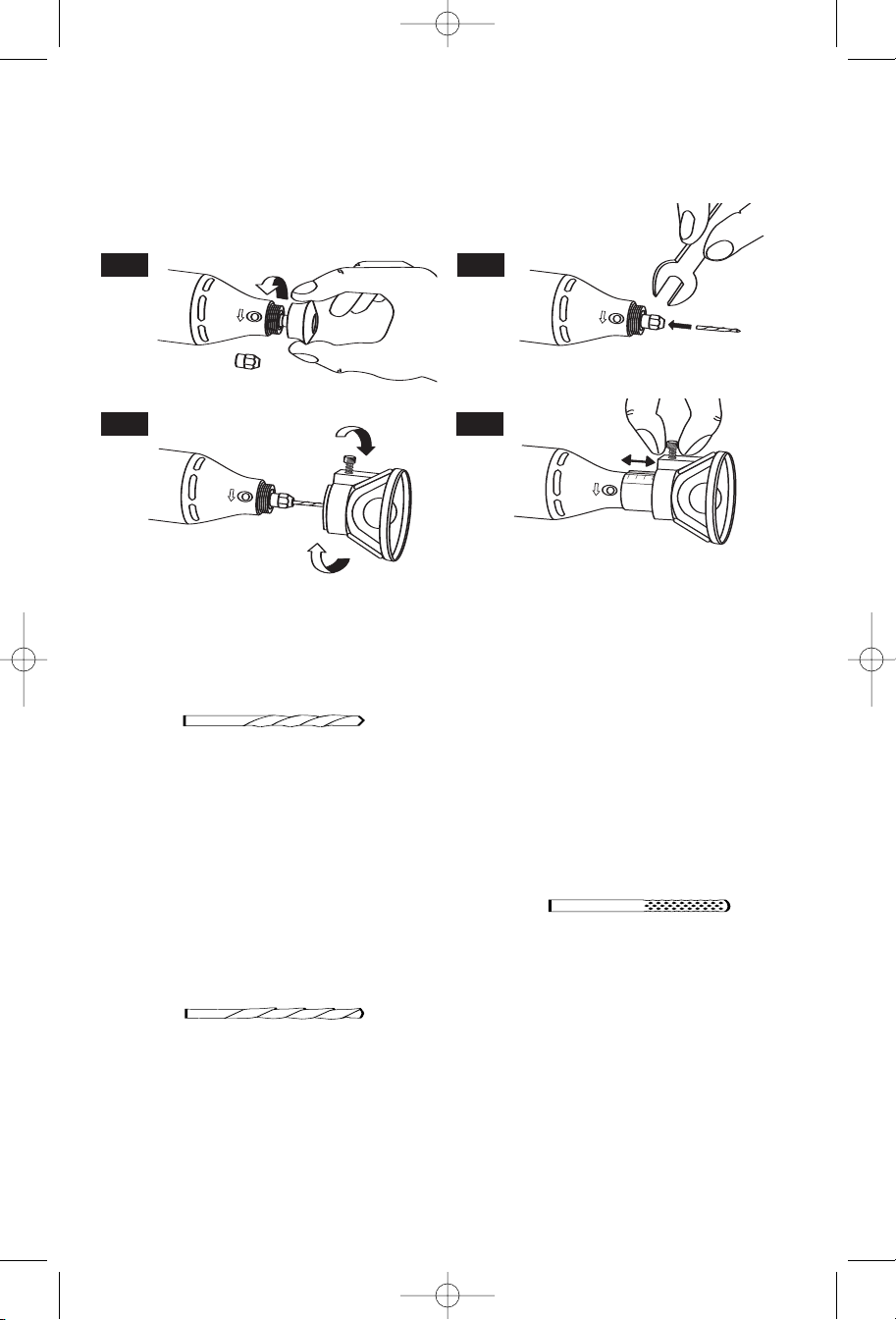
utting Guide Installation
C
The cutting guide 565 (sold separately) comes
completely assembled and ready to use. For use in a
variety of materials up to 19,1mm thick. Match the bit
Important: When viewing the tool from the top, the
bit rotates clockwise. Feed direction of cutting must
be counter-clockwise.
type to material to be cut. Always hold the tool firmly,
using slow steady pressure to make cuts.
To attach, follow the four steps shown below.
FIG. 1 FIG. 2
FIG. 3
Operating Instructions for Cutting Guide
Attachment
#560
Drywall Cutting Bit
For use in drywall.
• When inserting the #560 bit into your MultiPro tool,
make sure that the bit has been inserted as far as
possible.
• When making freehand cuts in drywall, example
repairing a hole in drywall, use the Multipurpose bit
#561, cutting in a clockwise direction. When using a
template (outlet box) behind the drywall, use the
drywall bit #560, cutting in a counter-clockwise
direction.
#561
Multipurpose Cutting Bit
For use in wood, plastics, drywall, fiberglass, vinyl
or aluminum siding, acoustical tile and laminates.
• When inserting the #561 bit into your MultiPro tool,
make sure that the bit has been inserted as far as
possible.
• When making freehand cuts in Drywall, example
repairing a hole in drywall, use the Multipurpose bit
FIG. 4
#561, cutting in a clockwise direction. When using a
template (outlet box) behind the drywall, use the
drywall bit #560, cutting in a counter-clockwise
direction.
• When using #561, Multipurpose Cutting Bit, and
#562, Tile Cutting Bit, start the bit into the material at
a 45 degree angle and then slowly bring it to a 90
degree angle to begin the cut.
#562
Tile Cutting Bit
For use on wall tile, cement board and plaster
• When inserting the #562 bit into your MultiPro tool,
it is very important that 1,6mm-3,2mm of smooth
shank remains visible above the collet.
• When using #561, Multipurpose Cutting Bit, and
#562, Tile Cutting Bit, start the bit into the material at
a 45 degree angle and then slowly bring it to a 90
degree angle to begin the cut.
• NOT FOR USE ON FLOOR TILE
Page 8
Page 9

a
aa
aa
a
a
a
a
a
a
a
a
a
a
a
aa
a
a
DM 2610934164 05-06 10/6/06 8:41 AM Page 9
Operating Instructions for Rotary Tool
and Flex-Shaft Attachment
The following operation applies to the Rotary Tool and Flex-Shaft attachment,
The Rotary Tool is a handful of high-speed power. It
serves as a carver, grinder, polisher, sander, cutter,
power brush, drill and more.
The Rotary Tool has a small, powerful electric motor, is
comfortable in the hand, and is made to accept a large
variety of accessories including abrasive wheels, drill
bits, wire brushes, polishers, engraving cutters, router
bits, and cutting wheels. Accessories come in a variety
of shapes and permit you to do a number of different
jobs. As you become familiar with the range of
accessories and their uses, you will learn just how
versatile the Rotary Tool is. You’ll see dozens of uses
you hadn’t thought of before.
The real secret of the Rotary Tool is its speed. To
understand the advantages of its high speed, you have
to know that the standard portable electric drill runs at
speeds up to 2.800 revolutions per minute. The Rotary
Tool operates at speeds up to 33.000 revolutions per
except the pictures depict the Rotary Tool.
minute. The typical electric drill is a low-speed, high
torque tool; the Rotary Tool is just the opposite – a
high-speed, low torque tool. The chief difference to the
user is that in the high speed tools, the speed
combined with the accessory mounted in the collet
does the work. You don’t apply pressure to the tool, but
simply hold and guide it. In the low speed tools, you
not only guide the tool, but also apply pressure to it, as
you do, for example, when drilling a hole.
It is this high speed, along with its compact size and
wide variety of special accessories, that makes the
Rotary Tool different from other power tools. The speed
enables it to do jobs low speed tools cannot do, such
as cutting hardened steel, engraving glass, etc.
Getting the most out of your Rotary Tool is a matter of
learning how to let this speed work for you.
Sharpen Tools Precise Drilling Shape Wood
Carve Wood
Deburr Metal
Page 9
Cut Metal
Page 10

a
a
WARNING
Wear Eye Protection
DM 2610934164 05-06 10/6/06 8:41 AM Page 10
sing the Rotary Tool
U
The first step in learning to use the Rotary Tool is to
get the “feel” of it. Hold it in your hand and feel its
weight and balance. Feel the taper of the housing. This
taper permits the Rotary Tool to be grasped much like
a pen or pencil.
When you turn on the tool for the first time, hold it
away from your face. Accessories can be damaged
during handling, and can fly apart as they come up to
speed. This is not common, but it does happen.
Practice on scrap materials first to see how the Rotary
Tool cuts. Keep in mind that the work is done by the
speed of the tool and by the accessory in the collet.
You should not lean on or push the tool into the work.
Questions or Problems ? Call 03-5415317
or check our website at www
Instead, lower the spinning accessory lightly to the
work and allow it to touch the point at which you want
cutting (or sanding or etching, etc.) to begin. Concentrate on guiding the tool over the work using very
little pressure from your hand. Allow the accessory to
do the work.
Usually, it is best to make a series of passes with the
tool rather than attempt to do all the work in one pass.
To make a cut, for example, pass the tool back and
forth over the work, much as you would a small paint
brush. Cut a little material on each pass until you reach
the desired depth. For most work, the gentle touch is
best. With it, you have the best control, are less likely
to make errors, and will get the most efficient work out
of the accessory.
.Dremel.com
For best control in close work, grip the Rotary Tool
like a pencil between your thumb and forefinger.
The “handgrip” method of holding the tool is used
for operations such as grinding a flat surface or
using cutoff wheels.
CAUTION
!
with your hand. This blocks the air flow and causes
the motor to overheat.
Page 10
Whenever you hold the tool, be
careful not to cover the air vents
Page 11

DM 2610934164 05-06 10/6/06 8:41 AM Page 11
Operating Speeds for Accessories
Electronic Feedback Circuitry (EFC)
Your tool is equipped with a internal electronic
feedback system that provides a "soft start", which
will reduce the stresses that occur from a high
torque start. The system also helps to keep the
pre-selected rotating speed virtually constant
between no-load and load conditions.
Set the speed indicator to fit the job; to achieve the
best job results when working with different materials, the speed of the Rotary Tool should be
regulated. Model 398-49 Rotary Tool has an
integral speed control.
!
CAUTION
tool.
To select the right speed for each job, use a
practice piece of material. Vary speed to find the
best speed for the accessory you are using and the
job to be done.
NOTE: Speed is affected by voltage changes. A
reduced incoming voltage will slow the RPM of the
tool, especially at the lowest setting. If your tool
appears to be running slowly increase the speed
setting accordingly.
An external speed control
should never be used with this
Digital Speed Selector Switch
Your rotary tool features a digital speed selector
switch which displays an L.C.D. reading of the tool’s
RPM. The speed can be selected from 5.000 RPM to
33.000 RPM in 1.000 RPM increments by simply
depressing the positive or negative buttons on the
switch.
TO TURN TOOL "ON": slide ON/OFF switch to the
"ON" position.
TO TURN TOOL "OFF": slide ON/OFF switch to the
"OFF" position.
TO INCREASE SPEED: depress button with + sign.
TO DECREASE SPEED: depress button with - sign.
Needs for Slower Speeds
Certain materials, however, (some plastics, for example) require a relatively slow speed because at
high speed the friction of the accessory generates
heat and causes the plastic to melt.
Slow speeds (15.000 RPM or less) usually are best
for polishing operations employing the felt polishing
accessories. They may also be best for working on
delicate projects as “egger
carving and fragile model parts. All brushing
applications require lower speeds to avoid wire
discharge from the holder
Higher speeds are better for carving, cutting, routing,
shaping, cutting dadoes or rabbets in wood.
y” work, delicate wood
.
Hardwoods, metals and glass require high speed
operation, and drilling should also be done at high
speeds.
The point to remember is this: You can do the great
majority of work at its regular speed of 33.000 RPM.
But for certain materials and types of work, you need
slower speeds — which is the reason the variable
speed models were developed.
To aid you in determining the optimum operational
speed for different materials and different
accessories, we have constructed a series of tables
that appear on page 13, 14, and 15. By referring to
these tables, you can discover the recommended
speeds for each type of accessory. Look these tables
over and become familiar with them.
Ultimately, the best way to determine the correct
speed for work on any material is to practice for a
few minutes on a piece of scrap, even after referring
to the chart. You can quickly learn that a slower or
faster speed is more effective just by observing what
happens as you make a pass or two at different
speeds. When working with plastic, for example,
start at a slow rate of speed and increase the speed
until you observe that the plastic is melting at the
point of contact. Then reduce the speed slightly to
get the optimum working speed.
Some rules of thumb in regard to speed:
1. Plastic and materials that melt at low
temperatures should be cut at low speeds.
2. Polishing, buffing and cleaning with a wire brush
must be done at speeds below 15.000 RPM to
prevent damage to the brush.
3. Wood should be cut at high speed.
4. Iron or steel should be cut at top speed if using
tungsten carbide accessory, but at slower speeds
if using high speed steel cutters. If a high speed
steel cutter starts to chatter — this normally
means it is running too slow.
5. Aluminum, copper alloys, lead alloys, zinc alloys
and tin may be cut at various speeds, depending
on the type of cutting being done. Use paraffin or
other suitable lubricant on the cutter to prevent
the cut material from adhering to the cutter teeth.
Increasing the pressure on the tool is not the answer
when it is not cutting as you think it should. Perhaps
you should be using a different cutter, and perhaps
an adjustment in speed would solve the problem. But
leaning on the tool seldom helps.
Use only Dremel Tested, High Performance Accessories.
Page 11
Page 12

DM 2610934164 05-06 10/6/06 8:41 AM Page 12
GLASS
CERAMIC
STONE
SHELL/
ALUMINUM,
BRASS, ETC.
STEEL
• Depending on cutting direction relative to grain.
* Speed for light cuts, caution burning on deep grooves.
PLASTIC
LAMINATES
HARD
WOOD
9.000-11.000
18.000-24.000
25.000-33.000
5.000-9.000
9.000-11.000
18.000-24.000
HIGH SPEED CUTTERS
9.000-11.000*
9.000-11.000*
12.000-17.000*
25.000-33.000*
12.000-17.000*
25.000-33.000*
5.000-9.000
9.000-11.000
25.000-33.000
25.000-33.000
5.000-9.000
9.000-11.000
12.000-17.000
12.000-17.000
9.000-11.000
12.000-17.000
12.000-17.000
5.000-8.000
9.000-11.000
9.000-11.000
9.000-11.000
12.000-17.000
12.000-17.000
12.000-17.000
12.000-17.000
18.000-24.000
18.000-24.000
18.000-24.000
18.000-24.000
18.000-24.000
5.000-8.000
9.000-11.000
9,000-11,000
18.000-24.000
ENGRAVING CUTTERS
9.000-11.000*
9.000-11.000*
25.000-33.000*
25.000-33.000*
9.000-11.000*
12.000-17.000*
25.000-33.000*
18.000-24.000*
12.000-17.000*
12.000-17.000*
18.000-24.000*
9.000-11.000*
25.000-33.000*
25.000-33.000*
25.000-33.000*
25.000-33.000*
5.000-11.000*
9.000-11.000*
9.000-11.000*
9.000-11.000*
9.000-11.000*
9.000-11.000*
RUBBER POLISHING POINT
12.000-17.000*
12.000-17.000*
25.000-33.000*
25.000-33.000*
25.000-33.000
25.000-33.000
25.000-33.000
25.000-33.000
25.000-33.000
25.000-33.000
25.000-33.000
25.000-33.000
CUTTING ACCESSORIES
5.000-9.000*
5.000-9.000*
•
Use only Dremel Tested, High Performance Accessories.
9.000-11.000•
12,000-25,000•
9.000-11.000•
12.000-17.000•
25.000-33.000•
HIGH SPEED ROUTER BITS (Use with cutting guide or shaper/router table)
SPEED SETTINGS
SOFT
WOOD
25.000-33.000*
197
198
NUMBER
CATALOG
189, 190
14, 124, 134, 144
1
100, 121, 131, 141
115, 178
192, 194
118, 191, 193
116, 117, 125, 196
199
Page 12
25.000-33.000*
25.000-33.000*
25.000-33.000*
10
107, 1
105, 108
106, 109
25.000-33.000*
25.000-33.000*
25.000-33.000*
111
112
113
425, 427
18.000-24.000*
18.000-24.000*
18.000-24.000*
25.000-33.000*
25.000-33.000*
25.000-33.000*
25.000-33.000*
25.000-33.000*
25.000-33.000*
12.000-25.000
560, 561, 562
409, 420, 426, 540
25.000-33.000*
25.000-33.000*
12.000-17.000*
12.000-17.000*
654
610
650, 652
612, 613, 614, 632, 640
Page 13

DM 2610934164 05-06 10/6/06 8:41 AM Page 13
GLASS
5.000-11.000
12.000-25.000
12.000-25.000
12.000-25.000
12.000-25.000
12.000-25.000
12.000-25.000
18.000-25.000
CERAMIC
SHELL/
ALUMINUM,
STEEL
• Depending on cutting direction relative to grain.
* Speed for light cuts, caution burning on deep grooves.
LAMINATES
18.000-33.000 18.000-33.000
STONE
18.000-24.000
BRASS, ETC.
DIAMOND WHEEL POINTS
PLASTIC
25.000-33.000
5.000-17.000
5.000-11.000
18.000-24.000
5.000-8.000
25.000-33.000
25.000-33.000
5.000-17.000
5.000-17.000
5.000-11.000
5.000-11.000
18.000-24.000
18.000-24.000
5.000-8.000
5.000-8.000
25.000-33.000
25.000-33.000
25.000-33.000
5.000-17.000
5.000-17.000
5.000-17.000
5.000-11.000
5.000-11.000
5.000-11.000
18.000-24.000
18.000-24.000
18.000-24.000
5.000-8.000
5.000-8.000
5.000-8.000
ALUMINUM OXIDE GRINDING STONES
HARD
WOOD
25.000-33.000
25.000-33.000
25.000-33.000
25.000-33.000
25.000-33.000
25.000-33.000
9.000-11.000
25.000-33.000
5.000-17.000
5.000-11.000
18.000-24.000
5.000-8.000
SILICON CARBIDE GRINDING STONES
12.000-25.000
12.000-25.000
5.000-8.000
5.000-8.000
5.000-11.000
5.000-11.000
5.000-11.000 5.000-8.000
25.000-33.000
25.000-33.000
25.000-33.000
12.000-17.000
12.000-17.000
12.000-17.000
12.000-25.000
12.000-25.000
12.000-25.000
12.000-25.000
5.000-8.000
5.000-8.000
5.000-8.000
5.000-8.000
5.000-11.000
5.000-11.000
5.000-11.000
5.000-11.000
25.000-33.000
25.000-33.000
25.000-33.000
25.000-33.000
12.000-17.000
12.000-17.000
TUNGSTEN CARBIDE CUTTERS
12.000-17.000
12.000-17.000
18.000-25.000
18.000-25.000 18.000-25.000
5.000-9.000
5.000-9.000
12.000-17.000
Use only Dremel Tested, High Performance Accessories.
25.000-33.000
SPEED SETTINGS
SOFT
WOOD
911, 921, 962
8173, 8174, 8175
Page 13
25.000-33.000
25.000-33.000
25.000-33.000
25.000-33.000
8215
973, 8184
903, 971, 8193
981, 8200, 8202
83702, 86442
83322, 83642,
85562
85422
84922
83142, 84382
85342, 85602
18.000-24.000 18.000-24.000 5.000-8.000 9.000-11.000
85622
9901, 9902,
9903, 9904,
9909, 9910, 9911
9905, 9906, 9912
25.000-33.000
18.000-24.000 18.000-24.000
NUMBER
CATALOG
7103, 7105, 7117,
7120, 7122, 7123,
25.000-33.000
7134, 7144
945, 997, 8153
541, 915, 923, 924,
913, 914, 943, 953, 954,
25.000-33.000
904, 922, 932
941, 952, 984,
8160, 8162, 8163
963, 964, 974, 992
Page 14

DM 2610934164 05-06 10/6/06 8:41 AM Page 14
GLASS
25.000-33.000
25.000-33.000
CERAMIC
STONE
SHELL/
ALUMINUM,
BRASS, ETC.
STEEL
• Depending on cutting direction relative to grain.
* Speed for light cuts, caution burning on deep grooves.
PLASTIC
LAMINATES
HARD
WOOD
5.000-25.000
5.000-25.000
5.000-25.000
5.000-25.000
5.000-25.000
5.000-25.000
25.000-33.000
25.000-33.000
25.000-33.000
25.000-33.000
25.000-33.000
25.000-33.000
SANDING ACCESSORIES
5.000-12.000
5.000-12.000
5.000-12.000
5.000-25.000
5.000-25.000
5.000-25.000
25.000-33.000
25.000-33.000
25.000-33.000
25.000-33.000
25.000-33.000
25.000-33.000
25.000-33.000
25.000-33.000
POLISHING ACCESSORIES
Use only Dremel Tested, High Performance Accessories.
SPEED SETTINGS
SOFT
WOOD
5.000-25.000
5.000-25.000
5.000-25.000
NUMBER
CATALOG
407, 408, 432
430, 431, 438
439, 440, 444
466, 414,429, 422, 423
461, 462, 463, 464, 465
Page 14
Page 15

DM 2610934164 05-06 10/6/06 8:41 AM Page 15
Maintenance
Service
!
WARNING
personnel may result in misplacing of internal wires
and components which could cause serious hazard.
We recommend that all tool service be performed by a
Dremel Service Facility.
CARBON BRUSHES
The brushes and commutator in your tool have been
engineered for many hours of dependable service. To
maintain peak efficiency of the motor, we recommend
every two to six months the brushes be examined. Only
genuine Dremel replacement brushes specially
designed for your tool should be used.
BRUSH
Preventive maintenance
performed by unauthorized
BRUSH
DOOR
CURVED END OF
BRUSH MUST
MATCH CURVATURE
OF HOUSING
FIG. 1
FIG. 2
BRUSH
SPRING
MAINTENANCE OF REPLACEABLE BRUSHES
MODEL 398-49
The brushes should be inspected frequently when
tools are used continuously. If your tool runs sporadically, loses power, makes unusual noises or runs at a
reduced speed, check the brushes. To continue using
the tool in this condition will permanently damage
your tool.
To Remove Brush Door
Disconnect the tool from the power supply. Each
brush door is held in place by a snap latch. To
disengage latch, place screwdriver end of wrench
(included) in slot at rear of door and pry up as
shown in Figure 1. With latch disengaged, using a
little force, pull up rear of door and lift away brush
door and spring assembly from housing, Figure 2.
Check Both Brushes
Turn tool so the brush falls out of holder and check
each brush. If the brush is less than 3,2mm long and
the end surface of the brush that contacts the
commutator is rough and/or pitted, they should be
replaced. Check both brushes. Usually the brushes will
not wear out simultaneously. If one brush is worn out,
replace both brushes. Make sure the brushes are
installed as illustrated. The curved surface of the
brush must match the curvature of the commutator.
To Replace Brush Door
Rest squared underside of brush door on the
squared cavity openings. Check to be sure the spring
rests on the V groove of the brush, Figure 3. Push
front of door down into the slot, Figure 4, then push
down and snap the rear latch into it’s slot, Figure 5.
After replacing brushes the tool should be run at noload; place it on a clean surface and run it freely for 5
Any Questions Call
03-5415317
FIG. 3
Page 15
Page 16

DM 2610934164 05-06 10/6/06 8:41 AM Page 16
FIG. 4
FIG. 5
minutes before loading (or using) the tool. This will
allow the brushes to “seat” properly and will give you
more hours of life from each set of brushes. This will
also extend the total life of your tool since the
commutator surface will “wear” longer.
BEARINGS
Model 398-49 has ball bearing construction. Under
normal use no additional lubrication is required.
Cleaning
!
WARNING
power supply before cleaning or performing any
maintenance. The tool may be cleaned most effectively
with compressed dry air. Always wear safety goggles
when cleaning tools with compressed air.
Ventilation openings and switch levers must be kept
clean and free of foreign matter. Do not attempt to clean
by inserting pointed objects through openings.
!
CAUTION
Some of these are: gasoline, carbon tetrachloride,
chlorinated cleaning solvents, ammonia and household
detergents that contain ammonia.
To avoid accidents always
disconnect the tool from the
Certain cleaning agents and
solvents damage plastic parts.
Extension Cords
!
WARNING
adequate size conductors that is capable of
carrying the current necessary for your tool must
be used. This will prevent excessive voltage drop,
loss of power or overheating. Grounded tools must
use 3-wire extension cords that have 3-prong plugs
and receptacles.
RECOMMENDED SIZES OF EXTENSION CORDS
240 VOLT ALTERNATING CURRENT TOOLS
Max. Tool
Ampere Rating
10 10 1,0 25
10 15 1,5 32
If an extension cord is
necessary, a cord with
Cord Ampere
Rating
Cord Sizes in
2
mm
Cord Length
in Meters
Page 16
Page 17

DM 2610934164 05-06 10/6/06 8:41 AM Page 17
Dremel Accessories
WARNING
!
The number and variety of accessories for the Rotary
Tool are almost limitless. There is a category suited to
almost any job you might have to do — and a variety
of sizes and shapes within each category which enables you to get the perfect accessory for every need.
Refer to the DREMEL ACCESSORY ORDER FORM for
illustrations of the accessories available. These
accessories may be found at your local hardware,
hobby or home center dealers.
Collets
If you expect to use a variety of accessories, we
recommend that in the beginning you purchase a
complete set of four collets. Store these so that you will
have the proper size of collet for any accessory or drill
bit you want to use.
2,4mm,0,8mm and 1,6mm collets accommodate all
of the available Dremel accessories. 3,2mm collets
are included in most rotary tool kits.
Mandrels
A mandrel is a shank with a threaded or screw head,
which are required when you use polishing
accessories, cutting wheels, sanding discs, and polishing points. The reason mandrels are used is that
sanding discs, cutting wheels and similar accessories
must be replaced frequently. The mandrel is a permanent shank, allowing you to replace only the worn
head when necessary, thus saving the expense of
replacing the shaft each time.
Screw Mandrel No. 401
This is a screw mandrel used with the felt polishing tip
and felt polishing wheels. 3,2mm shank.
Small Screw Mandrel No. 402
This is a mandrel with a small screw at its tip, and is
used with emery and fiberglass cutting wheels, sanding
discs and polishing wheels. 3,2mm shank.
Use only Dremel Tested, High Performance Accessories. Other accessories are not
designed for this tool and may lead to personal injury or property damage.
Tungsten Carbide Cutters
These are tough, long-lived cutters for use on hardened
steel, fired ceramics and other very hard materials.
They can be used for engraving on tools and garden
equipment. 3,2mm shanks.
Engraving Cutters
This group has a wide variety of sizes and shapes, and
are made for intricate work on ceramics (greenware),
wood carvings, jewelry and scrimshaw. They often are
used in making complicated printed circuit boards.
They should not be used on steel and other very hard
materials but are excellent on wood, plastic and soft
metals. 2,4mm shank.
Currently, the 3,2mm,
Fast cutting, needle-sharp teeth for greater material
removal with minimum loading. Use on fiberglass,
wood, plastic, epoxy and rubber. 3,2mm and 6,4mm
shank.
Aluminum Oxide Grinding Stones (red/brown)
Round, pointed, flat — you name the shape and there is
one available in this category. These are made of
aluminum oxide and cover virtually every possible kind
of grinding application. Use them for sharpening lawn
mower blades, screwdriver tips, knives, scissors, chisels
and other cutting tools. Use to remove flash from metal
castings, deburring any metal after cutting, smoothing
welded joints, grinding off rivets and removing rust.
These grinding stones can be resharped with a dressing
stone. In machine shops, high speed drills and cutters
normally are ground with aluminum oxide wheels.
3,2mm shank.
Structured Tooth
Tungsten Carbide Cutters
Threaded Tip Mandrel No. 424
This is a mandrel with a threaded tip which threads into
the polishing point accessor
y No. 427. 3,2mm shank.
High Speed Cutters
Available in many shapes, high speed cutters are used
in carving, cutting and slotting in wood, plastics and
soft metals such as aluminum, copper and brass. These
are the accessories to use for freehand routing or
carving in wood or plastic, and for precision cutting.
Made of high quality steel. 3,2mm shank.
Silicon Carbide Grinding Stones (blue/green)
Tougher than aluminum oxide points, these are made
especially for use on hard materials such as glass and
ceramics. Typical uses might be the removal of stilt
marks and excess glaze on ceramics and engraving on
glass. 3,2mm shank.
Diamond Wheel Points
Excellent for fine detail work on wood, jade, ceramic,
glass and other hard material. Bits are covered with
diamond particles. 2,4mm shanks.
Page 17
Page 18

DM 2610934164 05-06 10/6/06 8:41 AM Page 18
olishing Accessories
Wire Brushes
Three different shapes of wire brushes are available.
Never use wire brushes at speeds greater than
15.000 RPM. Refer to Operating Speeds section for
proper tool speed setting. The three shapes come in
three different materials: stainless steel, brass and
carbon wire. The stainless steel perform well on
pewter, aluminum, stainless steel, and other metals,
without leaving "after-rust". Brass brushes are non
sparking, and softer than steel; making them good for
use on soft metal like gold, cooper and brass. The
carbon wire brushes are good for general purpose
cleaning.
P
These include an impregnated polishing point and an
impregnated polishing wheel for bringing metal surfaces to smooth finish; a felt polishing tip and felt
polishing wheel, and cloth polishing wheel, all used for
polishing plastics, metals, jewelry and small parts. Also
included in this group is a polishing compound (No.
421) for use with the felt and cloth polishers.
Polishing points make a very smooth surface, but a
high luster is obtained using felt or cloth wheels and
polishing compound. For best results polishing
accessories should be used at speeds not greater
than 15.000 RPM. Refer to Operating Speeds section
for proper tool speed setting.
No polishing compound is needed when using the
425 Polishing Wheel or 427 Polishing point.
Bristle Brushes
These are excellent cleaning tools on silverware, jewelry and antiques. The three shapes make it possible to
get into tight corners and other difficult places. Bristle
brushes can be used with polishing compound for
faster cleaning or polishing.
Aluminum Oxide Abrasive Wheels
Brushing Pressure
1. Remember, the tips of a wire brush do the work.
Operate the brush with the lightest pressure so only
the tips of the wire come in contact with the work.
2. If heavier pressures are used, the wires will be
overstressed, resulting in a wiping action; and if this
is continued, the life of the brush will be shortened
due to wire fatigue.
3. Apply the brush to the work in such a way that as
much of the brush face as possible is in full contact
with the work. Applying the side or edge of the brush
to the work will result in wire breakage and shortened
brush life.
CORRECT:
Wire tips doing the work.
INCORRECT:
Excessive pressure can cause wire breakage.
Use to remove paint, deburr metal, polish stainless
steel and other metals. Available in fine and medium
grits. 3,2mm shank.
Sanding Accessories
Sanding discs in fine, medium and coarse grades are
made to fit mandrel No. 402. They can be used for
nearly any small sanding job you might have, from
model making to fine furniture finishing. In addition,
there is the drum sander, a tiny drum which fits into the
Rotary Tool and makes it possible to shape wood,
smooth fiberglass, sand inside curves and other difficult places, and other sanding jobs. You replace the
sanding bands on the drum as they become worn and
lose their grit. Bands come in fine and coarse grades.
Flapwheels grind and polish flat or contoured surfaces.
They are used most effectively as a finishing sander
after heavier surface sanding and material removal is
completed. Flapwheels come in fine and coarse grades.
Buffs are a great finishing accessor
light sanding. They work effectively on metal, glass,
wood, aluminum and plastics. Coarse and medium
buffs are sold together
y for cleaning and
. 3,2mm shank.
Grinding Wheel
Use for deburring, removing rust, and general purpose
grinding. Use with Mandrel #402.
Page 18
Page 19

DM 2610934164 05-06 10/6/06 8:41 AM Page 19
Dremel Accessories - (Cont.)
Tile Cutting Bit
Cutting Wheels
These thin discs of emery or fiberglass are used for
slicing, cutting off and similar operations. Use them for
cutting off frozen bolt heads and nuts, or to reslot a
screw head which has become so damaged that the
screwdriver won’t work in it. Fine for cutting BX cable,
small rods, tubing, cable and cutting rectangular holes
in sheet metal.
Cuts ceramic wall tile, cement board, and plaster.
Spiral Cutting Bit
Cuts through all types of wood and wood composites.
Drywall Cutting Bit
Gives you fast, clean cuts in drywall.
Mandrel No. 401 is used with the felt polishing tip and wheels. Thread the tip on to the screw carefully. The felt
tip must thread down straight on the screw Mandrel, and be turned all the way to the collar.
High Speed Router Bits
For routing, inlaying, and mortising in wood and other
soft materials. Use only with Dremel No. 330 Router
attachment or No. 231 Shaper/Router table.
Mandrel No. 402 has a small screw at its tip, and is used with emery cutting wheels and sanding discs. Higher
speeds, usually maximum, are best for most work, including cutting steel. Which is shown here.
Page 19
Page 20

DM 2610934164 05-06 10/6/06 8:41 AM Page 20
The machine-screw threading on Mandrel No. 424 threads into polishing point No. 427. This and other
threaded mandrels must be screwed firmly down to the collar before being used.
To replace a band on the Drum Sander, loosen the screw without removing it to contract the drum then slide
the old band off. Slide the new sanding band on and then expand the drum by tightening the screw once again.
WARNING
!
band is loose on the drum during operation it may “fly” off and strike you or bystanders.
Before each use, check to make certain that all components are assembled to accessory
shank and that the drum is sufficiently expanded to secure the band during use. If sanding
Dremel Attachments
565
Multipurpose Cutting Kit
• Includes 2 drywall cutting bits (560) and 1 spiral
cutting bit (561)
• Cuts fiberglass, wood & drywall easily
566
Tile Cutting Kit
• Includes 1 ceramic tile cutting bit (562)
• Cuts ceramic wall tile to any shape
Questions or Problems? Call 03-5415317
Page 20
Page 21

DM 2610934164 05-06 10/6/06 8:41 AM Page 21
Dremel Attachments
Add these Dremel attachments to your compact workshop and make your Rotary Tool more versatile.
Shapes, edges, chamfers, cuts, rabbets, dadoes, etc.
Adjustable edge guide can be easily removed for
freehand routing. The Model 330 can be used with
Models 270, 275, 280, 285, 380, 395, 398, and 850.
For precision drilling, routing, grooving, 15,2mm
square work surface, 0 to 7,6mm throat depth. T
slotted for guides, hold downs. Holds Models 275,
285, 395, 398, and 850.
Model 330 Router Attachment
Model 212 Drill Press
able
Allows finger-tip control for tight corners and hardto-reach areas. 1,07m long cable attaches to Models
275, 285, 395, 398, and 850. Pencil-like 12,7mm
diameter hand piece is cool-running and ideal for
light duty wood carving and other uses.
Converts the Rotar
shaper
professional quality slotting, edge trimming, grooving
and sanding of irregular shapes accurately and with
ease. Large 20,3cm x 15,2cm worktable. Use with
Models: 270, 275, 280, 285, 370, 380, 395, 398, and
850.
Page 21
Model 225 Flex-Shaft
Model 231 Shaper/Router Table
. Clamp it to a workbench and per
ool into a bench mounted wood
y T
form
Page 22

DM 2610934164 05-06 10/6/06 8:41 AM Page 22
23
810
825
801
4
16
5
824
2
801
22
825
826
3
28
650
30
824
27
MODEL 400 SERIES
Pagina 22
Page 23

DM 2610934164 05-06 10/6/06 8:41 AM Page 23
ORDER BY PART NUMBER, NOT CODE NUMBER
2 2615298792 Field Assembly
3 2610907942 Armature & Bearing Assembly
4 2610928648 Control Panel Assembly
5 2610999103 Cord
23 2615294043 Hanger
27 2615297355 Collet Nut
22 2615302505 Rubber bearing ring
16 2615302530 Brush Holder Assembly
30 2610913684 Housing Cap
28 2615000480 Collet
650 2610930692 Wrench
801 2610928647 Housing Set
810 2610907940 Brush (pair)
826 2615302807 Collet Lock Assembly
824 2615294035 Screws (includes 5)
825 2610928650 Brush Door w/ Spring (pair)
CODE NO. PART NO. DESCRIPTION
Pagina 23
Page 24

DM 2610934164 05-06 10/6/06 8:41 AM Page 24
7
10
6
8
DREMEL CUTTING GUIDE
9
5
4
Driver Cap
Flexible Shaft Core
Overthrow Nut Assembly
Guide
Guide insert
Screw spring & nut
DREMEL FLEX-SHAFT ATTACHMENT
3
2
ORDER BY PART NUMBER, NOT CODE NUMBER
1
Page 24
1 2615297355 Collet Nut (Not included)
CODE NO. PART NO. DESCRIPTION
483 0,8mm Collet available as Accessory (Not included)
482 1,6mm Collet available as Accessory (Not included)
481 2,4mm Collet available as Accessory (Not included)
2615294178
2610914543
2610915085
2615302049
2615302102
2615302103
7
4 90962 Wrench Available as Accessory (Not included)
2 480 3,2mm Collet available as Accessory (Not included)
3 2610914485 Handpiece Cap
8
5
6
9
10
 Loading...