


ESSENCE
SHOWER / TUB DOOR INSTALLATION INSTRUCTIONS
IMPORTANT |
Reserved |
DreamLine® reserves the right to alter, modify or redesign products at any time without prior notice for the |
|
|
DreamLine |
purpose of product improvement and customer experience. Please refer to the model’s web page on DreamLine.com for the latest technical drawings, installation manuals, warranty information or additional product details.
© Rights
All
model#s |
|
|
Reservedmodel# |
##=finish |
|
SHDR-6348760-## |
DreamLine |
|
G- Gray Glass |
||
|
Rights |
|
SHDR-6360600-## |
||
|
|
|
01Chrome |
||
© |
|
|
|
04Brushed Nickel |
|
SHDR-6360760-## |
|
|
|
|
|
|
All |
|
|
09Satin Black |
|
|
|
|
|
||
Please review this entire manual prior to installation
For more information about DreamLine® Shower Doors & Tub Doors please visit DreamLine.com
ESSENCE Shower and Tub Door manual Ver 1 Rev 2b 07/2020 |
©2020 DreamLine. All Rights Reserved |

|
Reserved |
DreamLine |
|
© |
Rights |
All |
|
This model is treated with DreamLine’s exclusive ClearMaxTM Glass technology. This is a specially formulated coating that prevents the buildup of soap and water spots.
Install the surface with the ClearMaxTM
label towards the inside of the shower. |
|
Please note that depending on the |
|
model, the glass may be coated on |
|
either one or both surfaces. |
|
|
Reserved |
DreamLine |
|
For best results, squeegee the glass after |
|
each use and dry with a soft cloth. |
|
© |
Rights |
All |
|
ESSENCE Shower and Tub Door manual Ver 1 Rev 2b 07/2020 |
©2020 DreamLine. All Rights Reserved |

Table of Contents
Section Title |
|
|
|
|
Page # |
|
|
|
|
|
|
Preparation |
|
|
|
|
2 |
Tools |
|
|
|
|
3 |
|
|
|
|||
Detailed Diagram of Shower Door Components |
|
4 |
|||
|
|
|
|
|
|
|
|
|
|
Reserved |
|
Guide Block |
|
DreamLine |
10-13 |
||
Anti-Water Side Strips |
14, 18 |
||||
Parts List |
|
|
|
|
5 |
Installation Steps |
|
|
Rights |
6-23 |
|
|
© |
|
|
|
|
Roller Guards |
|
|
|
|
19 |
Wheel Assembly AdjustmentAll |
|
21 |
|||
Product Maintenance |
|
|
|
23 |
|
|
Reserved |
DreamLine |
|
© |
Rights |
All |
|
ESSENCE Shower and Tub Door manual Ver 1 Rev 2b 07/2020
<![endif]>©2020 DreamLine. All Rights Reserved

Preparation
1. Prior to installation, examine all boxes and packages for shipping damage and compare the piece count with your packing slip. After opening all boxes and packages read this introduction carefully. Check that all of the needed parts are included in the package by checking off the components on the “Detailed Diagram of Shower Door Components”. If the unit has been damaged, has a finishing defect, or has missing parts, please contact our customer support department within 3 business days of the delivery date. Please note that DreamLine®
|
1 |
2 |
will not replace any damaged products or missing parts free of charge after 3 business days or if the |
||
product has been installed. Feel free to contact |
|
® if you have any questions and please provide an |
order number, job name or other proof of purchase to help identify the original order. |
||
|
Reserved |
|
DreamLine |
||
2. Please note that you should consult your local building codes with questions on installation compliance |
||
3. If this unit is going to be installedRightsin a new construction, please install all of the required plumbing and |
||
standards. Building and plumbing codes may vary by location, and DreamLine® is not responsible for code |
||
© |
|
|
compliance standards for your project and will not accept any returns.
drainage before installingAllthe shower. Use a competent and licensed (if required by local code) plumber for all plumbing installation.
4. Please make sure that prior to beginning the installation, the surfaces are leveled and solid and will be able to support the total weight of the unit. Also make sure the walls are at right angles. Irregular installation surface level, radius corners or improper angle of side walls will result in serious problems for your installation. Please, note that some adjustments and drilling might be necessary during the installation process.
5. Please protect all primary surfaces of the product during installation. Never set your glass down directly onto a tile floor. Leave corner protectors in place until necessary to remove them. Always use a piece of wood or cardboard to protect the bottom edge and corners of the glass prior to and during installation.
6. This unit must be installed upon a finished threshold and against finished walls.
7. Note: The installation of this unit requires that you drill down into the threshold. Contact the manufacturer of the base, tub or threshold material with any questions regarding the drilling of holes into their product.
8. This model can accommodate up to 1/4“ of out-of-plumb by adjusting the rollers on the door glass.
9.Threshold must be levelDreamLinefor proper installation.
10.This model requires©a minimum 2-3/4” of flat level threshold space for installation.
11.These instructions will show the installation of the shower door as an example. Please follow the same steps for the installation of the tub door.
12.Professional installation recommended. Reserved
NOTE: DO NOT install the towel bars onto the glass until instructed.
!DO NOT lift the glass using the towel bars. This could result in damage to the glass and/or serious personal injury. Always use an assistant or a professional grade glass suction cup when handling heavy glass.
ESSENCE Shower and Tub Door manual Ver 1 Rev 2b 07/2020
<![endif]>©2020 DreamLine. All Rights Reserved
2
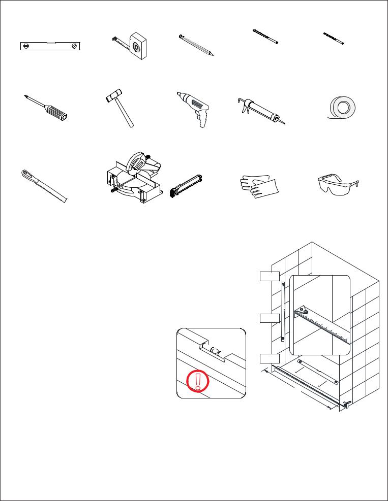
Tools
|
|
Tape |
|
Drill bit |
Drill bit |
Level |
|
Pencil |
(Ø5/16") |
(Ø1/8") |
|
|
Measure |
(Ø8mm) |
(Ø3mm) |
||
|
|
|
Reserved |
|
|
|
DreamLine |
|
|
||
Phillips |
© |
Rights |
|
|
|
Screwdriver |
Hammer |
Drill |
Silicone |
Painter’s Tape |
|
|
All |
|
|||
|
|
|
|
||
Metal File |
Miter saw or Hacksaw |
Work Gloves |
Safety Glasses |
Tip: Measure the finished opening before |
|
|
Top |
|
|
|
|
|
|
||
proceeding with the installation to be sure |
|
|
|
|
|
that the correct model size has been |
|
|
|
|
|
ordered. |
|
|
|
Middle |
|
|
|
Threshold must be level. |
|
||
|
|
|
|
||
Tip: Prior to installation, cover the |
|
Reserved |
|
||
shower/tub drain with tape to prevent |
|
|
|||
losing screws or small parts. |
|
|
|
||
DreamLine |
Bottom |
|
|||
|
|
||||
© |
|
|
|
|
|
Tip: Set screw gun clutch to low setting |
|
|
|
|
|
|
Rights |
! |
|
W |
|
when installing screws andAllbolts to |
|
|
|||
prevent stripping the heads. |
|
|
|
|
|
NOTE: Unpack your unit carefully and inspect it. Identify all parts using the detailed diagram and packing list in this manual as a reference. Before discarding the carton, check for small hardware bags that may have fallen to the bottom of the box. If any parts are damaged or missing, please contact DreamLine® for replacement. The shipping boxes may contain extra parts not used in your model configuration.
NOTE: Retain these installation instructions for future reference.
ESSENCE Shower and Tub Door manual Ver 1 Rev 2b 07/2020
<![endif]>©2020 DreamLine. All Rights Reserved
3
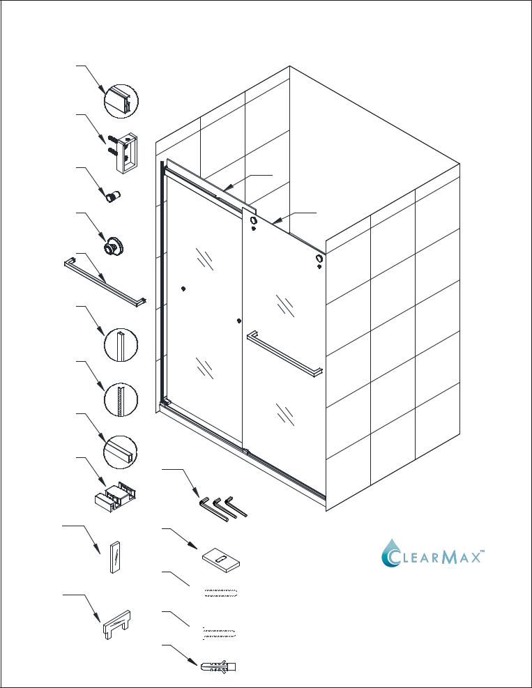
Detailed Diagram of Shower Door Components
1
2
3
4
5
6
7
8
9
10
11
|
Reserved |
|
DreamLine |
|
|
© |
Rights |
|
12 |
|
|
All |
13 |
|
|
|
|
|
inside door glass |
|
outside door glass
|
Reserved |
DreamLine |
|
14 |
Rights |
© |
|
15 |
|
All |
|
16 |
|
17 


 18
18 


The glass surface with the ClearMax™ label must be installed to face inside of the shower
ESSENCE Shower and Tub Door manual Ver 1 Rev 2b 07/2020
<![endif]>©2020 DreamLine. All Rights Reserved
4

Parts List
# |
|
Item |
|
|
|
|
Qty |
# |
Item |
|
Qty |
01 |
|
Upper Guide Rail |
|
|
|
|
1pc |
10 |
Upper Bumper |
|
4pcs |
05 |
|
Towel Bar |
|
|
|
|
2pcs |
14 |
ReservedAllen Wrench: 2.5mm / 3mm / 4mm |
|
1each |
02 |
|
Wall Bracket Assembly |
|
|
|
2pcs |
11 |
Bottom Bumper |
|
2pcs |
|
06 |
|
Wall Profile |
|
|
DreamLine2pcs 15 |
Guide Block Bracket |
|
3pcs |
|||
03 |
|
Roller Guard |
|
|
|
|
2pcs |
12 |
Inside Door Glass |
|
1pc |
04 |
|
Roller |
|
|
|
|
4pcs |
13 |
Outside Door Glass |
|
1pc |
|
|
|
|
|
|
Rights |
|
|
|
||
|
|
|
© |
|
|
|
|
|
|
|
|
07 |
|
Anti-Water Side Strip |
|
|
|
2pcs |
16 |
Countersunk Screw ST4.2 x 40 |
|
4pcs |
|
|
|
|
|
|
|
||||||
08 |
|
Bottom Rail |
|
All |
|
|
1pc |
17 |
Truss Head Screw ST4.2 x 40 |
|
3pcs |
|
|
|
|
|
|
||||||
09 |
|
Guide Block |
|
|
|
|
3pcs |
18 |
Ø5/16” (8mm) Wall Anchors |
|
7pcs |
|
|
|
|
|
|
|
|
Boxes |
|
|
|
|
|
|
|
|
|
|
|
|
|
|
|
# |
|
Box |
|
|
|
|
|
|
Package Contents by part# |
|
|
1 |
|
Glass Box |
|
|
|
|
|
7. 12. 13 |
|
|
|
2 |
|
Profile and Acc Box |
|
|
1. 2. 3. 4. 5. 6. 8. 9. 10. 11. 14. 15. 16. |
17. 18 |
|||||
3 |
|
Spare Acc Box |
|
|
|
|
|
10. 11 - 1 pc/ea |
|
|
|
|
|
|
|
Ø5/16” (8mm) Anchors, Countersunk Screw ST4.2x40 - 3pcs/ea |
|||||||
|
|
|
|
|
|
|
|||||
|
|
|
|
|
|
|
|
|
|
|
|
|
Reserved |
DreamLine |
|
© |
Rights |
All |
|
ESSENCE Shower and Tub Door manual Ver 1 Rev 2b 07/2020 |
5 |
<![endif]>©2020 DreamLine. All Rights Reserved
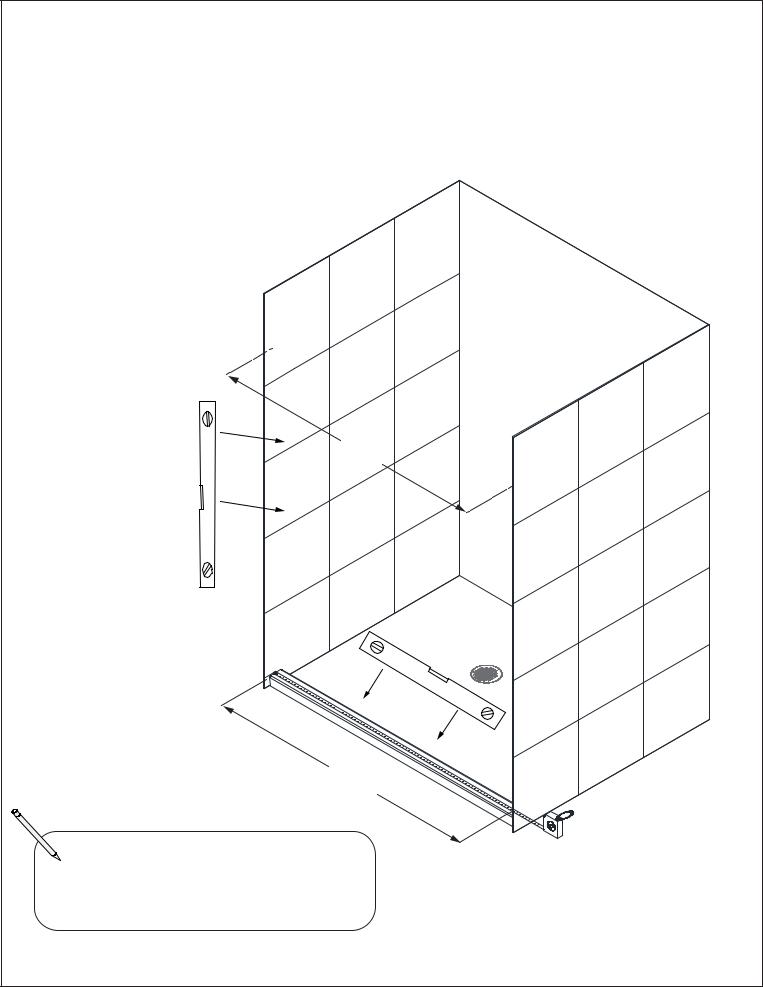
Installation Steps
1. Measure the finished opening width at the bottom and at the model height.
Use these dimensions as “W1” (top) and “W2”(bottom) in step #2. Also check the threshold for level and the walls for plumb. (Fig 1)
NOTE: This model will only accommodate up to 1/4” for out-of-plumb conditions.
|
Reserved |
DreamLine |
|
© |
Rights |
All |
|
W1
|
Reserved |
DreamLine |
|
© |
RightsW2 |
All |
|
_____________ |
Finished opening top (W1) |
_____________ |
Finished opening bottom (W2) |
Fig 1
ESSENCE Shower and Tub Door manual Ver 1 Rev 2b 07/2020
<![endif]>©2020 DreamLine. All Rights Reserved
6
 Loading...