


Shower Door, Shower Base and Backwalls Kit Installation Instruction
IMPORTANT |
|
DreamLine TM reserves the right to alter, modify or redesign products |
at any time without prior |
notice. For the latest up -to-date technical drawings, manuals or any other details please refer to the support.BathAuthority.com web page.
STEP 1: Install Shower Base
Shower Base Installation Instructions
STEP 2: Install Shower Backwalls
Shower Backwalls Installation Instructions
STEP 3: Install Shower Door
Shower Door Installation Instructions
|
|
|
Please read these instructions carefully before installing. If you have any q |
uestions |
regarding |
installation, please call our technical support specialists Monday through Friday 9:00 AM |
– 5:00 |
|
PM EST at Phone: 1-866 -731 -2244 , Fax : 1-866 -227 -1533 or e -mail our technical support group
at support@BathAuthority.com |
. |
|
||
|
|
|
|
|
For more information on |
DreamLi neTM Shower Door s please visit www.BathAuthority.com |
|||
|
|
|
|
|

FLEX
SHOWER DOOR INSTALLATION INSTRUCTIONS
IMPORTANT
DreamLineTM reserves the right to alter, modify or redesign products at any time without prior notice. For the latest up-to-date technical drawings, manuals or any other details please refer to the support.BathAuthority.com web page.
Please read these instructions carefully before installing. If you have any questions regarding installation, please call our technical support specialists Monday through Friday 9:00 AM – 5:00 PM EST at Phone: 1-866-731-2244, Fax: 1-866-227-1533 or e-mail our technical support group at support@BathAuthority.com.
For more information on DreamLineTM Shower Doors please visit www.BathAuthority.com

Preparation
1.After opening all boxes and packages, read this introduction carefully. Check that all of the needed parts are included in the package by marking all the components on the “Detailed Diagram of Shower Door Components”. Examine boxes and packages for shipping damage. If the unit has been damaged, has a finishing defect, or is missing parts, please contact our customer support department within 5 business days of the delivery date. Please note that DreamLineTM will not replace any damaged products or missing parts free of charge after 5 business days or if the product has been installed. Feel free to contact DreamLineTM if you have any questions.
2.Please note that you should consult your local building codes with questions on installation compliance standards. Building and plumbing codes may vary by location, and DreamLine is not responsible for code compliance standards for your project and will not accept any returns.
3.If this unit is going to be installed in a new construction, please, install all of the required plumbing and drainage before installing the shower. Use a competent and licensed (if required by local code) plumber for all plumbing installation period.
4.Prior to installation, please ensure that the installation surface is level and solid and will be able to support the total weight of the unit. Also, make sure that the walls are plumb. Depending on the type of unit you are installing, some adjustments in leveling may be possible. However, irregular installation, surface level or out of square conditions can result in serious problems for your installation. Please note that some adjustments and drilling may be necessary. Please protect all primary surfaces of the product during installation. Never set your glass down directly onto a tile floor. Always use a piece of wood or cardboard to protect the bottom edge and corners of the glass.
Tools Required
|
Tape |
|
Phillips |
Drill bit |
Caulk |
Pencil |
(Ø=5/16") |
||
Measure |
Screwdriver |
|
|
Caulk |
Electric |
|
Drill bit |
|
Level |
Hammer |
(Ø=1/8") |
|||
Gun |
|||||
Drill |
|
||||
“FLEX” Rev.2, Ver.2 |
03/2014 |
|
|
2 |

Detailed Diagram of Shower Door Components
1
3 


 2
2
1
4
5
6
13 7 


8
Part List
01 |
Wall profile |
2pcs |
06 |
Decorative cover |
8pcs |
02 |
Door assembly |
1set |
07 |
Flanged anti-water strip |
1pc |
03 |
Wall anchor |
8pcs |
08 |
Bottom anti-water strip |
1pc |
04 |
Round head screw ST4.2x10 |
8pcs |
13 |
Handle |
1pc |
05 |
Round head screws ST4.2×40 |
8pcs |
|
|
|
NOTE: Unpack your unit carefully and inspect it. Lay it out and identify all parts using detailed diagram and packing list in your manual as a reference. Before discarding the carton, check for small hardware bags that tend to fall to the bottom of the box. If any parts are damaged or missing, please contact DreamLineTM for replacement.
NOTE: Retain these installation instructions for future reference.
“FLEX” Rev.2, Ver.2 03/2014 |
3 |
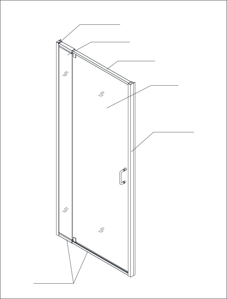
Door Assembly Diagram
Alluminum profile
Stationary glass
Expandable rail
Glass door
Alluminum profile
Expandable rail
“FLEX” Rev.2, Ver.2 03/2014 |
4 |
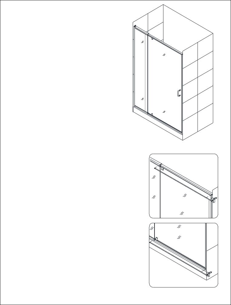
Shower Door Installation
NOTE: The installation of this door requires two installers.
NOTE: The door can be installed on the shower base or custom threshold.
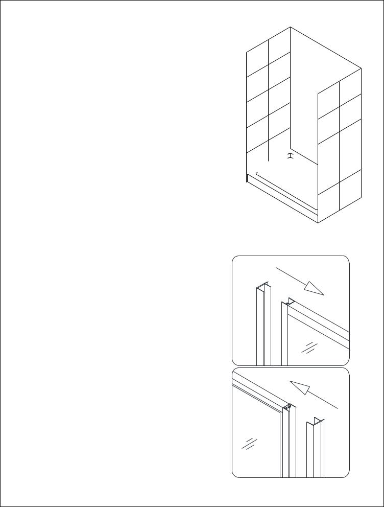
1.Prior to the Shower door installation, Shower base installation and plumbing must be completed.
See Fig. 1 for details.
W 

2.Push the Wall profiles (01) over the Door assembly
(02)on both sides. Be sure that the flanges with predrilled holes are pointing in towards the shower.
See Fig. 2 & Fig. 3 for details.
Fig. 1
1
2
Fig. 2
“FLEX” Rev.2, Ver.2 03/2014 |
5 |
NOTE:
Flip the entire assembly for opposite installation.
Fig. 3
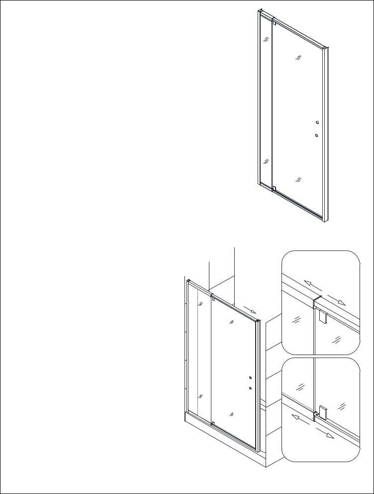
3.Move the Door assembly (02) with the Wall profiles (01) on the Shower base with Stationary glass side tight to the wall. Pull Glass door side of the Door assembly by stretching top and bottom Expanding rails to extend the Door assembly towards the opposite side of the wall. If your top and bottom wall opening measurements are different or if the walls are out-of- plumb, make adjustments by slightly pulling the Wall profiles out of the Door assembly.
NOTICE:
The maximum adjustable lengths of the Expanding rails are: 4 1/2”.
See Fig. 4 for details.
 1
1
2
Fig. 4
“FLEX” Rev.2, Ver.2 03/2014 |
6 |

4.Level the Door assembly (02) vertically using a level.
See Fig. 5 for details.
5.Have second installer hold the Door assembly (02) in the correct position; mark the wall through the predrilled holes on the flange of the Wall Profiles (01).
See Fig. 6 for details.
Fig. 5
1
Inside
2
Outside
Inside
Fig. 6
“FLEX” Rev.2, Ver.2 03/2014 |
7 |

6. Set the Door assembly (02) aside; drill the holes using |
1 |
|
|
Ø5/16” drill bit and insert the Wall anchors (03). |
Ø 5/16” |
|
See Fig. 7 for details.
2
|
Fig. 7 |
7. Apply silicone along the Wall Profiles (01) and |
1 |
around the holes on the wall. |
|
Place the Wall Profiles back on the Shower base |
|
into correct position and secure them to the walls |
|
using the Round head screws ST4.2×40 (05). |
|
See Fig. 8 and Fig. 9 for details. |
2 |
|
3
Fig. 8
“FLEX” Rev.2, Ver.2 03/2014 |
8 |

1
2
3
Fig. 9
8.Place the Door assembly (02) back onto the Shower base.
See Fig. 10 for details.
Fig. 10
“FLEX” Rev.2, Ver.2 03/2014 |
9 |
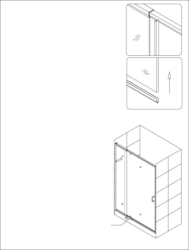
9.Install the Handle (13) onto the Door assembly (02).
Insert the Door assembly (02) with the Stationary glass side into the Wall profile (01).
See Fig. 11 for details.
10.Extend the Door assembly (02) toward the other wall and insert Glass door side into the
Wall profile (01).
See Fig. 12 and Fig. 13 for details.
1
2
Fig. 10
Fig. 11
Fig. 12
“FLEX” Rev.2, Ver.2 03/2014 |
10 |
11.Make sure the Door assembly (02) is fully extended inside the Wall profiles (01).
Adjust top and bottom Expanding rails to the same length. Use a tape measure for accuracy.
See Fig. 14 for details.
Fig. 13
1
2
Fig. 14
“FLEX” Rev.2, Ver.2 03/2014 |
11 |

12.Drill holes in top and bottom Expanding rails through the predrilled holes using Ø 1/8” drill bit.
ATTENTION:
Do not drill the Expanding rail throughout, only the first layer.
Secure the Expanding rails using Round head screws ST4.2×10 (04) with the raised white washers.
Cover exposed screw heads with Decorative covers (06).
See Fig. 15 for details.
13. Do the final adjustments of the |
|
|
Door assembly (02) in the Wall |
1 |
|
profiles (01). Open and close the |
||
Glass door to make sure that the |
|
|
magnetic strips are fully attracted |
|
|
to each other. |
|
|
Drill the holes in the aluminum |
|
|
profile of the Door assembly |
|
|
through predrilled holes in the |
|
|
Wall profile using Ø 1/8” drill bit. |
|
|
ATTENTION: |
2 |
|
Do not drill the profiles |
||
|
||
throughout, only the first layer. |
|
|
Secure the Door assembly inside |
|
|
the Wall profile using the Round |
|
|
head screws ST4.2×10 (04). |
|
|
Cover the exposed screw heads |
|
|
with the Decorative covers (06). |
|
|
See Fig. 16 for details. |
|
1 |
4 |
Ø 1/8" |
|
|
Ø 1/8" |
2 |
5 |
3 |
6 |
Fig. 15 |
|
3 |
|
Ø 1/8"
Fig. 16
“FLEX” Rev.2, Ver.2 03/2014 |
12 |
14.Attach Flanged Anti-water strip (07) to the vertical edge of the Stationary glass.
Cut Bottom Anti-water strip (08) in two pieces to cover the bottom edge of the door from pivot to both sides of the Glass door.
Attach both pieces of the Bottom Anti-water strip to the bottom edge of the Glass door.
See Fig. 17 for details.
15.Apply sealant along the connection of the Wall profiles (01) and inside wall of shower and the connection of the bottom Expanding rail and Shower
base from both inside and outside the shower.
See Fig. 18 for details.
1
Outside
2
Fig. 17
Caulk
Fig. 18
“FLEX” Rev.2, Ver.2 03/2014 |
13 |

Product Maintenance
To ensure long lasting life for your acrylic back walls, wipe them off after each use with a soft cloth. To clean the acrylic back walls use non-abrasive sprays or cream based cleaners. Never use abrasive cleansers, metal brushes or scrapers that could scratch or dull the surface.
To ensure long lasting life for your glass shower products, wipe them off after each use with a soft cloth. Rinse and wipe off the glass using either soft cloth or squeegee to prevent soap buildup. Never use abrasive cleaners and cleaning products that contain scouring agents as this may scratch the surface. Never use bristle brushes or abrasive sponges.
To ensure a long lasting hardware finish, wipe off the metal parts after each use with a soft cloth. Do not use abrasive cleaners or cleaning products containing ammonia, bleach or acid. If accidentally used, rinse the surface as soon as possible to prevent finish peeling or corrosion. After cleaning the shiny finishes, rinse thoroughly and wipe dry with soft cloth. Clean stainless steel surfaces at least once a week. When applying stainless steel cleaner or polish, work with (not against) the grain. Never use an abrasive sponge or cloth, steel wool or wired brushes.
“FLEX” Rev.2, Ver.2 03/2014 |
14 |

SLIMLINE SHOWER BASE
SHOWER BASE DIMENSIONS AND INSTALLATION INSTRUCTIONS
IMPORTANT
DreamLineTM reserves the right to alter, modify or redesign products at any time without prior notice. For the latest up-to-date technical drawings, manuals or any other details please refer to the support.BathAuthority.com web page.
Please read these instructions carefully before installing. If you have any questions regarding installation, please call our technical support specialists Monday through Friday 9:00 AM – 5:00 PM EST at Phone: 1-866-731-2244, Fax: 1-866-227-1533 or e-mail our technical support group at support@BathAuthority.com.
For more information on DreamLineTM Shower Bases please visit www.BathAuthority.com
 Loading...