


Aqua

AQUA
SHOWER / TUB DOOR INSTALLATION INSTRUCTIONS
IMPORTANT
DreamLine
prior notice. For the latest up-to-date technical drawings, manuals or any other details
please refer to the support.BathAuthority.com
TM
reserves the right to alter, modify or redesign products at any time without
web page.
Please carefully read the instructions before installing. If you have any questions regarding
installation, please call our technical support specialists Monday through Friday 9:00 AM –
5:00 PM EST at 1-866-731-8378, ext. 3 or e-mail our technical support group at
support@BathAuthority.com.
For more information on DreamLineTM Shower Door and Tub Door please visit www.BathAuthority.com
Rev 2.2
1
Preparation
1. After opening all boxes and packages, read this introduction carefully. Check that all of the
needed parts are included in the package, by marking all the components on the “Detailed
Diagram of Shower/Tub Door Components”. Examine boxes and packages for shipping
damage. If the unit has been damaged, has a finishing defect, or has missing parts, please
contact our customer support department within 3 business days of the delivery date. Please
note that DreamLine
charge after 3 business days or if the product has been installed. Feel free to contact
DreamLine
2. If this unit is going to be installed in a new construction, please, install all of the required
plumbing and drainage before installing the shower. Use a competent and licensed (if
required by local code) plumber for all plumbing installation
3. Please note that you should consult your local building codes with questions on
installation compliance standards. Building and plumbing codes may vary by location,
and DreamLine is not responsible for code compliance standards for your project.
4. Please insure that prior to the installation the installation surface is leveled and solid and will be
able to support the total weight of the unit. Also make sure the walls are at right angles. While
some adjustment in leveling of the door is possible, irregular installation surface level or
improper angle of side walls will result in serious problems for your installation. Please, note
that some adjustments and drilling might be necessary during the installation process.
TM
if you have any questions.
TM
will not replace any damaged products or missing parts free of
Caulk
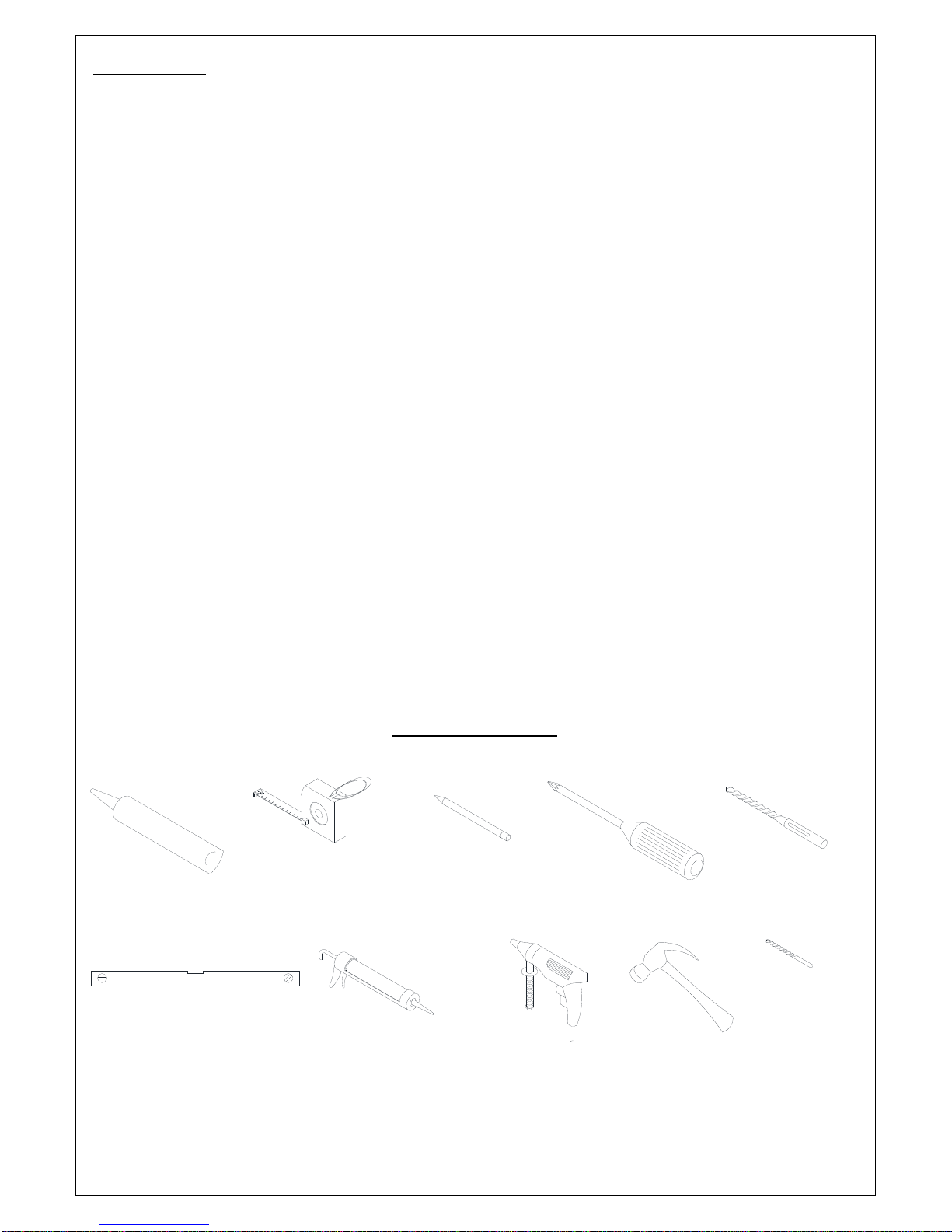
Level
Tools Required
Tape
Measure
Caulk
Gun
Pencil
Electric
Drill
Phillips
Screwdriver
Hammer
Drill bit
(Ø=5/16")
Drill bit
(Ø=1/8")
Rev 2.2
2
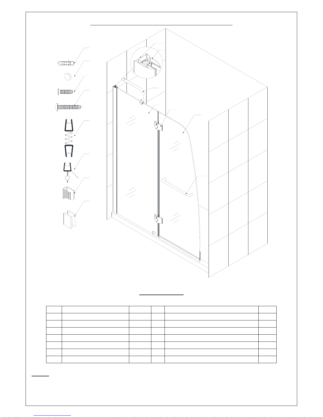
Detailed Diagram of Tub Door Components
1a
7
1b
8
9
10
11
12
13
14
3
2
4
5
6
01a Wall profile (External) 1pc 08 Decorative plug 4pcs
01b Wall profile (Internal) 1pc 09 Countersunk screw ST4.2×15 4pcs
02 St ation ary glass 1pc 10 Round head screw ST4.2×30 6pcs
03 Support bar 1pc 11 Connected anti-water strip 1pc
04 Hinge 2pcs 12 Bottom anti-water strip 1pc
05 Glass door 1pc 13 U-shape seal gasket 1pc
06 Handle 1pc 14 Bottom bracket 1pc
07 Wall anchor 5pcs 15 Screw cover 1pc
NOTE: Unpack your unit carefully and inspect it. Lay it out and identify all parts using the detailed
diagram and packing list in your manual as a reference. Before discarding the carton, check for
small hardware bags that tend to fall to the bottom of the box. If any parts are damaged or
missing, please contact DreamLine
Rev 2.2
Packing List
TM
for replacement.
3
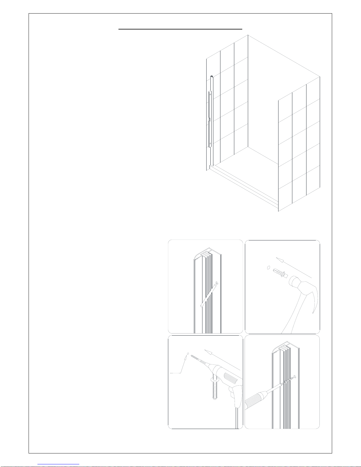
Shower/Tub Door Installation
1. Place the Wall profile (External) (01a) to the wall
above the Shower base or Tub and level it
vertically.
See Fig. 1 for details.
Fig
2. Mark the drilling holes on the wall
through the holes in the Wall profile
(External) (01a).
Place the Wall profile (External)
aside, drill the holes using Ø5/16” drill
bit and insert the Wall anchors (07).
Apply silicone caulk along the wall
profile and around the holes on the
wall.
Place the Wall profile (External)
back into the designated position and
secure it to the wall using the Round
head screws ST4.2×30 (10).
See Fig. 2 for details.
1
2
Ø5/16"
3
4
. 1
Fig. 2
Rev 2.2
4
 Loading...