

Page 1

RETURN TO THIS MANUAL'S TABLE OF CONTENTS
RETURN TO CD-ROM TABLE OF CONTENTS
Technical
Service
Manual
Part Number: 4114846-001
Date: 20 May 2002
© 2002 Draeger Medical, Inc.
Rev: R
Narkomed 6000
Anesthesia System
Page 2

RETURN TO THIS MANUAL'S TABLE OF CONTENTS
RETURN TO CD-ROM TABLE OF CONTENTS
Page 3

RETURN TO CD-ROM TABLE OF CONTENTS
Narkomed 6000 Service Manual Table of Contents
Summary of What's New in Rev. R
DESCRIPTION
SECTION 1:
Introduction . . . . . . . . . . . . . . . . . . . . . . . . . . . . . . . . . . . . . . . . . . . . . . . . . . . . . . . . . . . . . . . . . . . . . . 1-1
SECTION 2:
Diagnostics . . . . . . . . . . . . . . . . . . . . . . . . . . . . . . . . . . . . . . . . . . . . . . . . . . . . . . . . . . . . . . . . . . . . . . . 2-1
2.1 Accessing the Service Screens . . . . . . . . . . . . . . . . . . . . . . . . . . . . . . . . . . . . . . . . . . . . . . 2-2
2.2 Advanced Service Mode . . . . . . . . . . . . . . . . . . . . . . . . . . . . . . . . . . . . . . . . . . . . . . . . . . . 2-3
2.3 Service Monitors Notebook . . . . . . . . . . . . . . . . . . . . . . . . . . . . . . . . . . . . . . . . . . . . . . . . 2-3
2.4 Service Configuration Notebook . . . . . . . . . . . . . . . . . . . . . . . . . . . . . . . . . . . . . . . . . . . . 2-9
2.5 Service Dump Notebook . . . . . . . . . . . . . . . . . . . . . . . . . . . . . . . . . . . . . . . . . . . . . . . . . . 2-16
2.6 Service Log . . . . . . . . . . . . . . . . . . . . . . . . . . . . . . . . . . . . . . . . . . . . . . . . . . . . . . . . . . . . 2-17
2.6A Service Log Entry Detail . . . . . . . . . . . . . . . . . . . . . . . . . . . . . . . . . . . . . . . . . . . . . . . . 2-18B
2.7 NM6000 Event Log Transfer Using Service Laptop with Windows 95 or 98 . . . . . . . . 2-19
2.7A NM6000 Event Log Transfer Using Service Laptop with Windows NT . . . . . . . . . . . 2-23A
2.7B Event Log Transfer: Alternate Procedure . . . . . . . . . . . . . . . . . . . . . . . . . . . . . . . . . . . 2-23H
2.8 Divan Ventilator Power-up Self Test . . . . . . . . . . . . . . . . . . . . . . . . . . . . . . . . . . . . . . . . 2-24
2.9 Divan Service Mode . . . . . . . . . . . . . . . . . . . . . . . . . . . . . . . . . . . . . . . . . . . . . . . . . . . . . 2-29
SECTION 3:
Troubleshooting . . . . . . . . . . . . . . . . . . . . . . . . . . . . . . . . . . . . . . . . . . . . . . . . . . . . . . . . . . . . . . . . . . . 3-1
3.1 Power Supply and Voltage Distribution . . . . . . . . . . . . . . . . . . . . . . . . . . . . . . . . . . . . . . 3-1
3.2 Battery . . . . . . . . . . . . . . . . . . . . . . . . . . . . . . . . . . . . . . . . . . . . . . . . . . . . . . . . . . . . . . . . 3-4A
3.3 Troubleshooting Guides . . . . . . . . . . . . . . . . . . . . . . . . . . . . . . . . . . . . . . . . . . . . . . . . . . 3-4B
PAG E
SECTION 4:
Replacement Procedures . . . . . . . . . . . . . . . . . . . . . . . . . . . . . . . . . . . . . . . . . . . . . . . . . . . . . . . . . . . . 4-1
4.1 Cylinder Yoke Assemblies . . . . . . . . . . . . . . . . . . . . . . . . . . . . . . . . . . . . . . . . . . . . . . . . . 4-2
4.2 Cylinder Pressure Regulators . . . . . . . . . . . . . . . . . . . . . . . . . . . . . . . . . . . . . . . . . . . . . . 4-5
4.3 Cylinder and Pipeline Pressure Gauges . . . . . . . . . . . . . . . . . . . . . . . . . . . . . . . . . . . . . . 4-8
4.4 Flowmeters . . . . . . . . . . . . . . . . . . . . . . . . . . . . . . . . . . . . . . . . . . . . . . . . . . . . . . . . . . . . 4-11
4.5 Flow Control Valves . . . . . . . . . . . . . . . . . . . . . . . . . . . . . . . . . . . . . . . . . . . . . . . . . . . . . 4-14
4.6 Minimum O2 Flow Cutoff Solenoid . . . . . . . . . . . . . . . . . . . . . . . . . . . . . . . . . . . . . . . . . 4-17
4.7 Auxiliary Oxygen Flowmeter . . . . . . . . . . . . . . . . . . . . . . . . . . . . . . . . . . . . . . . . . . . . . . 4-20
4.8 Oxygen Supply Failure Protection Device . . . . . . . . . . . . . . . . . . . . . . . . . . . . . . . . . . . 4-23
4.9 Oxygen Supply Pressure Alarm Switch . . . . . . . . . . . . . . . . . . . . . . . . . . . . . . . . . . . . . 4-26
4.10 Oxygen Ratio Controller. . . . . . . . . . . . . . . . . . . . . . . . . . . . . . . . . . . . . . . . . . . . . . . . . . 4-29
4.11 O2 Flush Valve . . . . . . . . . . . . . . . . . . . . . . . . . . . . . . . . . . . . . . . . . . . . . . . . . . . . . . . . . 4-32
4.12 Ventilator Piston-Cylinder Diaphragm Replacement. . . . . . . . . . . . . . . . . . . . . . . . . . . 4-35
4.13 Divan Ventilator PCB Assemblies, Battery and EPROM Replacement . . . . . . . . . . . . 4-39
4.14 Breathing System and Diaphragm Valves . . . . . . . . . . . . . . . . . . . . . . . . . . . . . . . . . . . 4-44
4.15 Breathing System and Ventilator Lip Seals . . . . . . . . . . . . . . . . . . . . . . . . . . . . . . . . . . 4-47
4.16 Ventilator Replacement - Complete Assembly . . . . . . . . . . . . . . . . . . . . . . . . . . . . . . . . 4-49
4.17 Caster . . . . . . . . . . . . . . . . . . . . . . . . . . . . . . . . . . . . . . . . . . . . . . . . . . . . . . . . . . . . . . . . 4-53
4.18 Battery . . . . . . . . . . . . . . . . . . . . . . . . . . . . . . . . . . . . . . . . . . . . . . . . . . . . . . . . . . . . . . . 4-55
4.19 Power Supplies . . . . . . . . . . . . . . . . . . . . . . . . . . . . . . . . . . . . . . . . . . . . . . . . . . . . . . . . . 4-57
Rev. R
i
Page 4

CONTENTS (continued)
RETURN TO THIS MANUAL'S TABLE OF CONTENTS
RETURN TO CD-ROM TABLE OF CONTENTS
NM6000
DESCRIPTION
4.20 Workstation Processor Assembly (WPU). . . . . . . . . . . . . . . . . . . . . . . . . . . . . . . . . . . . . 4-60
4.21 VPO Assembly . . . . . . . . . . . . . . . . . . . . . . . . . . . . . . . . . . . . . . . . . . . . . . . . . . . . . . . . . 4-63
4.22 Vitalbus Hub PCB Assembly . . . . . . . . . . . . . . . . . . . . . . . . . . . . . . . . . . . . . . . . . . . . . . 4-66
4.23 Agent Analyzer Assembly; Lithium Battery (TK-RAM IRIA) Replacement. . . . . . . . . 4-68
4.23A GAP Pump Assembly Replacement. . . . . . . . . . . . . . . . . . . . . . . . . . . . . . . . . . . . . . . . 4-71A
4.23B IRIA Sensor Head Replacement . . . . . . . . . . . . . . . . . . . . . . . . . . . . . . . . . . . . . . . . . . 4-71C
4.23C GAP Personality PCB & Common Processor PCB Replacement . . . . . . . . . . . . . . . . . 4-71E
4.23D IRIA Controller PCB Replacement . . . . . . . . . . . . . . . . . . . . . . . . . . . . . . . . . . . . . . . . 4-71H
4.23E Water Trap, Solenoid, Variable Restrictor Replacement & Retubing Procedure . . . . 4-71K
4.24 CRT Assembly. . . . . . . . . . . . . . . . . . . . . . . . . . . . . . . . . . . . . . . . . . . . . . . . . . . . . . . . . . 4-72
4.24A Flat Panel Display Assembly . . . . . . . . . . . . . . . . . . . . . . . . . . . . . . . . . . . . . . . . . . . . . 4-75A
4.25 Table Lamp . . . . . . . . . . . . . . . . . . . . . . . . . . . . . . . . . . . . . . . . . . . . . . . . . . . . . . . . . . . . 4-76
4.25A Strip Chart Recorder Assembly . . . . . . . . . . . . . . . . . . . . . . . . . . . . . . . . . . . . . . . . . . . 4-77A
4.26 Flow Sensor. . . . . . . . . . . . . . . . . . . . . . . . . . . . . . . . . . . . . . . . . . . . . . . . . . . . . . . . . . . . 4-78
4.27 Oxygen Sensor . . . . . . . . . . . . . . . . . . . . . . . . . . . . . . . . . . . . . . . . . . . . . . . . . . . . . . . . . 4-80
4.28 Lower Frame Cover (skirt) Replacement . . . . . . . . . . . . . . . . . . . . . . . . . . . . . . . . . . . . 4-82
4.29 Divan Safety Plate Replacement . . . . . . . . . . . . . . . . . . . . . . . . . . . . . . . . . . . . . . . . . . . 4-84
4.30 WPU Mother Board Battery Replacement . . . . . . . . . . . . . . . . . . . . . . . . . . . . . . . . . . . 4-87
4.31 Vaporizer Mounting and Exclusion System Replacement . . . . . . . . . . . . . . . . . . . . . . . 4-96
4.32 Main Pneumatic Valve Replacement Procedure . . . . . . . . . . . . . . . . . . . . . . . . . . . . . . . 4-98
4.33 Divan Ventilator Front Bezel and Related Components Replacement . . . . . . . . . . . . 4-100
4.34 Integrated Patient Monitor Replacement Procedure . . . . . . . . . . . . . . . . . . . . . . . . . . 4-108
4.35 Divan Motor Drive Assembly Replacement . . . . . . . . . . . . . . . . . . . . . . . . . . . . . . . . . 4-111
4.36 Divan PEEP Valve Replacement . . . . . . . . . . . . . . . . . . . . . . . . . . . . . . . . . . . . . . . . . . 4-113
4.37 Divan Pressure Sensors Replacement. . . . . . . . . . . . . . . . . . . . . . . . . . . . . . . . . . . . . . 4-118
PAG E
SECTION 5:
Adjustment and Calibration Procedures . . . . . . . . . . . . . . . . . . . . . . . . . . . . . . . . . . . . . . . . . . . . . . . 5-1
5.1 Cylinder Pressure Regulator Adjustment . . . . . . . . . . . . . . . . . . . . . . . . . . . . . . . . . . . . . 5-2
5.2 Oxygen Supply Pressure Alarm Switch Adjustment . . . . . . . . . . . . . . . . . . . . . . . . . . . . 5-5
5.3 Oxygen Ratio Controller (ORC) Adjustment. . . . . . . . . . . . . . . . . . . . . . . . . . . . . . . . . . . 5-7
5.4 Oxygen Sensor Calibration . . . . . . . . . . . . . . . . . . . . . . . . . . . . . . . . . . . . . . . . . . . . . . . 5-10
5.5 Breathing Pressure Monitor Calibration . . . . . . . . . . . . . . . . . . . . . . . . . . . . . . . . . . . . 5-12
5.6 Agent Monitor Sample Flow Calibration . . . . . . . . . . . . . . . . . . . . . . . . . . . . . . . . . . . . 5-14
5.7 CRT Alignment . . . . . . . . . . . . . . . . . . . . . . . . . . . . . . . . . . . . . . . . . . . . . . . . . . . . . . . . . 5-16
5.7A Flat Panel Brightness, Contrast, Phase and Video Position Adjustments . . . . . . . . . 5-17A
5.8 Touch Screen Calibration . . . . . . . . . . . . . . . . . . . . . . . . . . . . . . . . . . . . . . . . . . . . . . . . . 5-18
5.8A Advanced Touch Screen Calibration . . . . . . . . . . . . . . . . . . . . . . . . . . . . . . . . . . . . . . . 5-19A
5.9 Ventilator Supply Pressure Adjustment . . . . . . . . . . . . . . . . . . . . . . . . . . . . . . . . . . . . . 5-20
5.10 Ventilator Supply Flow Adjustment . . . . . . . . . . . . . . . . . . . . . . . . . . . . . . . . . . . . . . . . 5-22
5.11 Ventilator Control Pressure Adjustment. . . . . . . . . . . . . . . . . . . . . . . . . . . . . . . . . . . . . 5-24
5.12 Breathing System Leveling Adjustment . . . . . . . . . . . . . . . . . . . . . . . . . . . . . . . . . . . . . 5-26
5.13 Bag Pole Friction Adjustment . . . . . . . . . . . . . . . . . . . . . . . . . . . . . . . . . . . . . . . . . . . . . 5-28
5.14 Right Vaporizer Vertical Adjustment . . . . . . . . . . . . . . . . . . . . . . . . . . . . . . . . . . . . . . . 5-29
5.15 System Electrical Switch Adjustment . . . . . . . . . . . . . . . . . . . . . . . . . . . . . . . . . . . . . . . 5-31
5.16 Local Time Zone Adjustment . . . . . . . . . . . . . . . . . . . . . . . . . . . . . . . . . . . . . . . . . . . . . . 5-33
5.17 Narkomed 6000 Alarm Volume Adjustment . . . . . . . . . . . . . . . . . . . . . . . . . . . . . . . . . . 5-36
SECTION 6:
PMS Procedure. . . . . . . . . . . . . . . . . . . . . . . . . . . . . . . . . . . . . . . . . . . . . . . . . . . . . . . . . . . . . . . . . . . . 6-1
Materials Required . . . . . . . . . . . . . . . . . . . . . . . . . . . . . . . . . . . . . . . . . . . . . . . . . . . . . . . . . . . . . . . . 6-2
ii
Rev. R
Page 5

RETURN TO THIS MANUAL'S TABLE OF CONTENTS
RETURN TO CD-ROM TABLE OF CONTENTS
NM6000
CONTENTS (continued)
DESCRIPTION PAG E
Periodic Manufacturers Certification General Instructions . . . . . . . . . . . . . . . . . . . . . . . . . . . . . . . . 6-3
PM Certification Procedure . . . . . . . . . . . . . . . . . . . . . . . . . . . . . . . . . . . . . . . . . . . . . . . . . . . . . . . . . . 6-6
6.1 Service Menu . . . . . . . . . . . . . . . . . . . . . . . . . . . . . . . . . . . . . . . . . . . . . . . . . . . . . . . . . . . 6-8
6.2 Battery Circuit . . . . . . . . . . . . . . . . . . . . . . . . . . . . . . . . . . . . . . . . . . . . . . . . . . . . . . . . . 6-11
6.3 Open Reservoir Scavenger - if applicable . . . . . . . . . . . . . . . . . . . . . . . . . . . . . . . . . . . . 6-12
6.4 Scavenger Interface, A/C - if applicable . . . . . . . . . . . . . . . . . . . . . . . . . . . . . . . . . . . . . 6-13
6.5 Suction Regulator . . . . . . . . . . . . . . . . . . . . . . . . . . . . . . . . . . . . . . . . . . . . . . . . . . . . . . . 6-14
6.6 Suction Switch . . . . . . . . . . . . . . . . . . . . . . . . . . . . . . . . . . . . . . . . . . . . . . . . . . . . . . . . . 6-15
6.7 High Pressure Leak . . . . . . . . . . . . . . . . . . . . . . . . . . . . . . . . . . . . . . . . . . . . . . . . . . . . . 6-16
6.8 Regulator and Gauges . . . . . . . . . . . . . . . . . . . . . . . . . . . . . . . . . . . . . . . . . . . . . . . . . . . 6-18
6.9 Oxygen Supply Failure Protection. . . . . . . . . . . . . . . . . . . . . . . . . . . . . . . . . . . . . . . . . . 6-22
6.10 Flowmeters . . . . . . . . . . . . . . . . . . . . . . . . . . . . . . . . . . . . . . . . . . . . . . . . . . . . . . . . . . . . 6-23
6.11 Oxygen Analyzer. . . . . . . . . . . . . . . . . . . . . . . . . . . . . . . . . . . . . . . . . . . . . . . . . . . . . . . . 6-25
6.12 Oxygen Concentration Tests . . . . . . . . . . . . . . . . . . . . . . . . . . . . . . . . . . . . . . . . . . . . . . 6-27
6.13 Oxygen Ratio Control . . . . . . . . . . . . . . . . . . . . . . . . . . . . . . . . . . . . . . . . . . . . . . . . . . . . 6-28
6.14 Fresh Gas Leak Test. . . . . . . . . . . . . . . . . . . . . . . . . . . . . . . . . . . . . . . . . . . . . . . . . . . . . 6-29
6.15 Minimum O2 Control Solenoid Test . . . . . . . . . . . . . . . . . . . . . . . . . . . . . . . . . . . . . . . . 6-30
6.16 Divan Maintenance . . . . . . . . . . . . . . . . . . . . . . . . . . . . . . . . . . . . . . . . . . . . . . . . . . . . . 6-31
6.17 Divan Service Mode . . . . . . . . . . . . . . . . . . . . . . . . . . . . . . . . . . . . . . . . . . . . . . . . . . . . . 6-35
6.18 Divan Operating Mode Tests . . . . . . . . . . . . . . . . . . . . . . . . . . . . . . . . . . . . . . . . . . . . . . 6-39
6.19 Respiratory Volume . . . . . . . . . . . . . . . . . . . . . . . . . . . . . . . . . . . . . . . . . . . . . . . . . . . . . 6-45
6.20 Pressure Monitor . . . . . . . . . . . . . . . . . . . . . . . . . . . . . . . . . . . . . . . . . . . . . . . . . . . . . . . 6-47
6.21 Agent Analyzer Accuracy Test . . . . . . . . . . . . . . . . . . . . . . . . . . . . . . . . . . . . . . . . . . . . . 6-49
6.22 O2 Flush Valve . . . . . . . . . . . . . . . . . . . . . . . . . . . . . . . . . . . . . . . . . . . . . . . . . . . . . . . . . 6-52
6.23 Reset Logbook . . . . . . . . . . . . . . . . . . . . . . . . . . . . . . . . . . . . . . . . . . . . . . . . . . . . . . . . . . 6-53
6.24 Electrical Safety . . . . . . . . . . . . . . . . . . . . . . . . . . . . . . . . . . . . . . . . . . . . . . . . . . . . . . . . 6-54
6.25 Vapor Exclusion System. . . . . . . . . . . . . . . . . . . . . . . . . . . . . . . . . . . . . . . . . . . . . . . . . . 6-55
6.26 Table Top Lamp . . . . . . . . . . . . . . . . . . . . . . . . . . . . . . . . . . . . . . . . . . . . . . . . . . . . . . . . 6-55
6.27 Flowmeter Lights . . . . . . . . . . . . . . . . . . . . . . . . . . . . . . . . . . . . . . . . . . . . . . . . . . . . . . . 6-55
6.28 CRT Fan . . . . . . . . . . . . . . . . . . . . . . . . . . . . . . . . . . . . . . . . . . . . . . . . . . . . . . . . . . . . . . 6-55
6.29 Operator’s Instruction Manual . . . . . . . . . . . . . . . . . . . . . . . . . . . . . . . . . . . . . . . . . . . . 6-56
6.30 Final Check . . . . . . . . . . . . . . . . . . . . . . . . . . . . . . . . . . . . . . . . . . . . . . . . . . . . . . . . . . . . 6-56
SECTION 6A:
PMS Procedure: Integrated Patient Monitoring Module . . . . . . . . . . . . . . . . . . . . . . . . . . . . . . . . . . 6A-1
6A.1 Electrical Safety Analysis . . . . . . . . . . . . . . . . . . . . . . . . . . . . . . . . . . . . . . . . . . . . . . . . 6A-3
6A.2 ECG Tests . . . . . . . . . . . . . . . . . . . . . . . . . . . . . . . . . . . . . . . . . . . . . . . . . . . . . . . . . . . . . 6A-5
6A.3 Battery Operation. . . . . . . . . . . . . . . . . . . . . . . . . . . . . . . . . . . . . . . . . . . . . . . . . . . . . . . 6A-7
6A.4 Defibrilator Synchronization Tests . . . . . . . . . . . . . . . . . . . . . . . . . . . . . . . . . . . . . . . . . 6A-8
6A.5 ST Segment Analysis . . . . . . . . . . . . . . . . . . . . . . . . . . . . . . . . . . . . . . . . . . . . . . . . . . . . 6A-9
6A.6 Invasive Blood Pressure . . . . . . . . . . . . . . . . . . . . . . . . . . . . . . . . . . . . . . . . . . . . . . . . . 6A-10
6A.7 Temperature Tests . . . . . . . . . . . . . . . . . . . . . . . . . . . . . . . . . . . . . . . . . . . . . . . . . . . . . 6A-16
6A.8 Cardiac Output Tests . . . . . . . . . . . . . . . . . . . . . . . . . . . . . . . . . . . . . . . . . . . . . . . . . . . 6A-17
6A.9 SPO2/Pulse . . . . . . . . . . . . . . . . . . . . . . . . . . . . . . . . . . . . . . . . . . . . . . . . . . . . . . . . . . . 6A-19
6A.10 NIBPStrip . . . . . . . . . . . . . . . . . . . . . . . . . . . . . . . . . . . . . . . . . . . . . . . . . . . . . . . . . . . 6A-21
6A.11 Chart Recorder Assembly. . . . . . . . . . . . . . . . . . . . . . . . . . . . . . . . . . . . . . . . . . . . . . . . 6A-23
6A.12 Final IPMM and Strip Chart Recorder Checks . . . . . . . . . . . . . . . . . . . . . . . . . . . . . . 6A-24
SECTION 7:
System Updates . . . . . . . . . . . . . . . . . . . . . . . . . . . . . . . . . . . . . . . . . . . . . . . . . . . . . . . . . . . . . . . . . . . 7-1
7.1 Exclusion System Update . . . . . . . . . . . . . . . . . . . . . . . . . . . . . . . . . . . . . . . . . . . . . . . . . 7-1
7.2 deleted . . . . . . . . . . . . . . . . . . . . . . . . . . . . . . . . . . . . . . . . . . . . . . . . . . . . . . . . . . . . . . . . . 7-3
Rev. P
iii
Page 6

CONTENTS (continued)
RETURN TO THIS MANUAL'S TABLE OF CONTENTS
RETURN TO CD-ROM TABLE OF CONTENTS
NM6000
DESCRIPTION
7.3 deleted . . . . . . . . . . . . . . . . . . . . . . . . . . . . . . . . . . . . . . . . . . . . . . . . . . . . . . . . . . . . . . . . . 7-5
7.4 deleted . . . . . . . . . . . . . . . . . . . . . . . . . . . . . . . . . . . . . . . . . . . . . . . . . . . . . . . . . . . . . . . . . 7-7
7.5 deleted . . . . . . . . . . . . . . . . . . . . . . . . . . . . . . . . . . . . . . . . . . . . . . . . . . . . . . . . . . . . . . . . . 7-8
7.6 Gas Analyzer Modifications . . . . . . . . . . . . . . . . . . . . . . . . . . . . . . . . . . . . . . . . . . . . . . . . 7-9
7.7 Installation of Flow Sensor Anti-rotation Bracket . . . . . . . . . . . . . . . . . . . . . . . . . . . . . 7-13
7.8 Installation of Bag Arm O-ring, Locking Knob, and Friction Screw Adjustment. . . . . 7-14
7.9 Lubrication of Ventilator Piston Rod. . . . . . . . . . . . . . . . . . . . . . . . . . . . . . . . . . . . . . . . 7-16
7.10 deleted . . . . . . . . . . . . . . . . . . . . . . . . . . . . . . . . . . . . . . . . . . . . . . . . . . . . . . . . . . . . . . . . 7-18
7.11 Vitalbus Hub Conversion to Single Com Port Configuration. . . . . . . . . . . . . . . . . . . . . 7-18
7.12 Divan Motor Drive Belt Lubrication . . . . . . . . . . . . . . . . . . . . . . . . . . . . . . . . . . . . . . . . 7-21
PAG E
iv
Rev. P
Page 7

RETURN TO THIS MANUAL'S TABLE OF CONTENTS
RETURN TO CD-ROM TABLE OF CONTENTS
NM6000
CONTENTS (continued)
DESCRIPTION PAG E
SECTION 8:
Spare and Replacement Parts . . . . . . . . . . . . . . . . . . . . . . . . . . . . . . . . . . . . . . . . . . . . . . . . . . . . . . . . 8-1
Monitor and touchscreen assembly, related parts . . . . . . . . . . . . . . . . . . . . . . . . . . . . . 8-2, 8-3
Flat panel display and related parts . . . . . . . . . . . . . . . . . . . . . . . . . . . . . . . . . . . . . 8-3A, 8-3B
Table lamp assembly . . . . . . . . . . . . . . . . . . . . . . . . . . . . . . . . . . . . . . . . . . . . . . . . . . . . 8-4, 8-5
Strip Chart Recorder Assembly . . . . . . . . . . . . . . . . . . . . . . . . . . . . . . . . . . . . . . . . . 8-5A, 8-5B
Gas analyzer assembly and components. . . . . . . . . . . . . . . . . . . . . . . . . . . . . . . . . . . . . 8-6, 8-7
Gas analyzer tubing and related items . . . . . . . . . . . . . . . . . . . . . . . . . . . . . . . . . . . 8-7A, 8-7B
Integrated Patient Monitoring Module . . . . . . . . . . . . . . . . . . . . . . . . . . . . . . . . . . . 8-7C, 8-7D
Divan piston-cylinder unit, lip seals . . . . . . . . . . . . . . . . . . . . . . . . . . . . . . . . . . . . . . . . 8-8, 8-9
Divan electronics assemblies, batteries . . . . . . . . . . . . . . . . . . . . . . . . . . . . . . . . . . . 8-10, 8-11
Absorber canister and diffuser . . . . . . . . . . . . . . . . . . . . . . . . . . . . . . . . . . . . . . . 8-11A, 8-11B
Divan motor drive assembly, pressure sensors, PEEP valve . . . . . . . . . . . . . . . . 8-11C, 8-11D
Divan breathing system . . . . . . . . . . . . . . . . . . . . . . . . . . . . . . . . . . . . . . . . . . . . . . . . 8-12, 8-13
Ultrasonic flow sensor, oxygen sensor, hose assemblies. . . . . . . . . . . . . . . . . . . . . . . 8-14, 8-15
Pipeline inlets . . . . . . . . . . . . . . . . . . . . . . . . . . . . . . . . . . . . . . . . . . . . . . . . . . . . . . . . 8-16, 8-17
Failsafe assemblies, ORC, O
supply pressure switch, min. flow O2 solenoid . . . . 8-18, 8-19
2
Flowmeter shield, knobs, gauges. . . . . . . . . . . . . . . . . . . . . . . . . . . . . . . . . . . . . . . . . 8-20, 8-21
Auxiliary O
flowmeter . . . . . . . . . . . . . . . . . . . . . . . . . . . . . . . . . . . . . . . . . . . . . . . . 8-22, 8-23
2
Suction switch, vacuum valve asm, cockpit sub-asm, main switch. . . . . . . . . . . 8-23A, 8-23B
Flow tubes, flow control valves . . . . . . . . . . . . . . . . . . . . . . . . . . . . . . . . . . . . . . . . . . 8-24, 8-25
Cylinder pressure regulators, O2 flush valve . . . . . . . . . . . . . . . . . . . . . . . . . . . . . . . 8-26, 8-27
Bag arm assembly . . . . . . . . . . . . . . . . . . . . . . . . . . . . . . . . . . . . . . . . . . . . . . . . . 8-27A, 8-27B
Cylinder yokes and related parts . . . . . . . . . . . . . . . . . . . . . . . . . . . . . . . . . . . . . . . . 8-28, 8-29
VPO assembly, interface assembly . . . . . . . . . . . . . . . . . . . . . . . . . . . . . . . . . . . . . . . 8-30, 8-31
Vitalbus assembly. . . . . . . . . . . . . . . . . . . . . . . . . . . . . . . . . . . . . . . . . . . . . . . . . . . . . 8-32, 8-33
Power supply, casters, processor and related items, cord retainer hardware. . . . . . 8-34, 8-35
Internal cables and wire harness assemblies . . . . . . . . . . . . . . . . . . . . . . . . . . . . . . . 8-36, 8-37
Open Reservoir Scavenger . . . . . . . . . . . . . . . . . . . . . . . . . . . . . . . . . . . . . . . . . . . . . . 8-38, 8-39
Scavenger, A/C, Vent Grill Adapter . . . . . . . . . . . . . . . . . . . . . . . . . . . . . . . . . . . . . . . 8-40, 8-41
Vapor mounting and exclusion system; paint, Loctite, Molykote, silicon adhesive . 8-42, 8-43
Boom Arm . . . . . . . . . . . . . . . . . . . . . . . . . . . . . . . . . . . . . . . . . . . . . . . . . . . . . . . . . . . 8-44, 8-45
Rev. R
v
Page 8

NARKOMED 6000 ANESTHESIA SYSTEM
GAS
INSTRUMENTATION
PANEL
AUXILIARY O2
FLOWMETER
RETURN TO THIS MANUAL'S TABLE OF CONTENTS
RETURN TO CD-ROM TABLE OF CONTENTS
MONITOR
SCREEN
ABSORBER
STRIP CHART
RECORDER
DIVAN
VENTILATOR
SV00285
1-0
Rev. H
Page 9

RETURN TO THIS MANUAL'S TABLE OF CONTENTS
RETURN TO CD-ROM TABLE OF CONTENTS
NM6000
INTRODUCTION
1.0 RECOMMENDATIONS
Because of the sophisticated nature of Draeger Medical, Inc. anesthesia equipment and its
critical importance in the operating room setting, it is highly recommended that only
appropriately trained and experienced professionals be permitted to service and maintain
this equipment. Please contact DrägerService
equipment.
Draeger Medical, Inc. also recommends that its anesthesia equipment be serviced at threemonth intervals. Periodic Manufacturer’s Service Agreements are available for equipment
manufactured by Draeger Medical, Inc. For further information concerning these
agreements, please contact us at (800) 543-5047.
®
at (800) 543-5047 for service of this
Draeger Medical, Inc.
HOW TO USE THIS MANUAL
products/material in need of factory repair shall be sent to:
DrägerService
3124 Commerce Drive
Telford, PA 18969 U.S.A.
(Include RMA Number)
The manual is divided into several sections. The DIAGNOSTICS section describes self-test
and service diagnostics for checking the system functions. An understanding of the on-board
service capabilities is necessary before any attempt is made to troubleshoot the unit. The
TROUBLESHOOTING section lists error codes and provides troubleshooting guides to
assist the Technical Service Representative in locating the source of a problem. The
REPLACEMENT PROCEDURES section contains instructions for removal and replacement
of assemblies that are considered field-replaceable. The ADJUSTMENT AND
CALIBRATION PROCEDURES section contains the field procedures needed to restore
original system specifications. The Periodic Manufacturer’s Service (PMS) PROCEDURE
section outlines the steps required to verify the electrical, mechanical and pneumatic safety
of the unit and also identifies components requiring periodic replacement.
GENERAL TROUBLESHOOTING GUIDELINES
Troubleshooting the Narkomed 6000 should always begin by communicating with those who
observed or experienced a problem with the unit. This may eliminate unnecessary
troubleshooting steps. Once a general problem is identified, refer to the troubleshooting flow
charts in Section 3 to determine the proper corrective action to be taken.
After any component is replaced, verify that the unit is operating properly by running the
appropriate diagnostic procedure. The PMS PROCEDURE in Section 6 must also be
performed after any component is replaced.
The general arrangement of the Narkomed 6000 anesthesia system is shown on the opposite
page.
1-1
Page 10

RETURN TO THIS MANUAL'S TABLE OF CONTENTS
RETURN TO CD-ROM TABLE OF CONTENTS
NM6000INTRODUCTION (continued)
WARNINGS
Warnings are used in this manual before procedures which if not performed correctly could
result in personal injury.
CAUTIONS
Cautions are used in this manual to alert service personnel to the possibility of damage to
the equipment if a procedure is not performed correctly.
Copyright
Copyright© 2001 by Draeger Medical, Inc. All rights reserved. No part of this publication
may be reproduced, transmitted, transcribed, or stored in a retrieval system in any form or
by any means, electronic or mechanical, including photocopying and recording, without
written permission of Draeger Medical, Inc.
Trademark Notices
Narkomed, Narkomed GS, Vigilance Audit, Vitalert and Vitalink are registered trademarks
of Draeger Medical, Inc. All other products or name brands are trademarks of their
respective owners.
Disclaimer
The content of this manual is furnished for informational use only and is subject to change
without notice. Draeger Medical, Inc. assumes no responsibility or liability for any errors or
inaccuracies that may appear in this manual.
1-2
Page 11

RETURN TO THIS MANUAL'S TABLE OF CONTENTS
RETURN TO CD-ROM TABLE OF CONTENTS
NM6000 DIAGNOSTICS
2.0 DIAGNOSTICS
The Narkomed 6000 contains a diagnostic system that monitors certain system functions
and records their operational status. A series of tests is performed when the system is
powered up and the results are displayed on the monitor screen. At the completion of the
diagnostics, one of three screens will appear as shown in the following examples:
SYSTEM 1 PASS
VPO Pod PASS
GAP Pod PASS
VENTILATOR PASS
SYSTEM FUNCTIONAL
SYSTEM 1 PASS
VPO Pod PASS
GAP NVRAM failure FAIL
VENTILATOR PASS
SYSTEM CONDITIONALLY FUNCTIONAL
press key to continue
SYSTEM 1 PASS
VPO Pod Firmware FAIL
GAP Pod PASS
VENTILATOR FAIL
SYSTEM NON-FUNCTIONAL
Continue
Continue
Continue
The screen labeled SYSTEM FUNCTIONAL indicates that all tests have passed. This screen
will be displayed for approximately five seconds, and the system will then proceed to the
monitor screen. (Touching the Continue key will bring up the monitor screen immediately.)
The screen labeled SYSTEM CONDITIONALLY FUNCTIONAL indicates that a problem
has been detected but the system is still usable. This screen will remain displayed until the
Continue key is touched.
The SYSTEM NON-FUNCTIONAL screen indicates that a serious problem has been
detected. The system will not proceed any further.
Further diagnostic functions are available through service screens that can be accessed at
the monitor. The following pages provide a description of the service screens. If no display is
present upon system power-up, refer to Section 3 of this manual for troubleshooting
assistance.
2-1
Page 12
DIAGNOSTICS (continued)
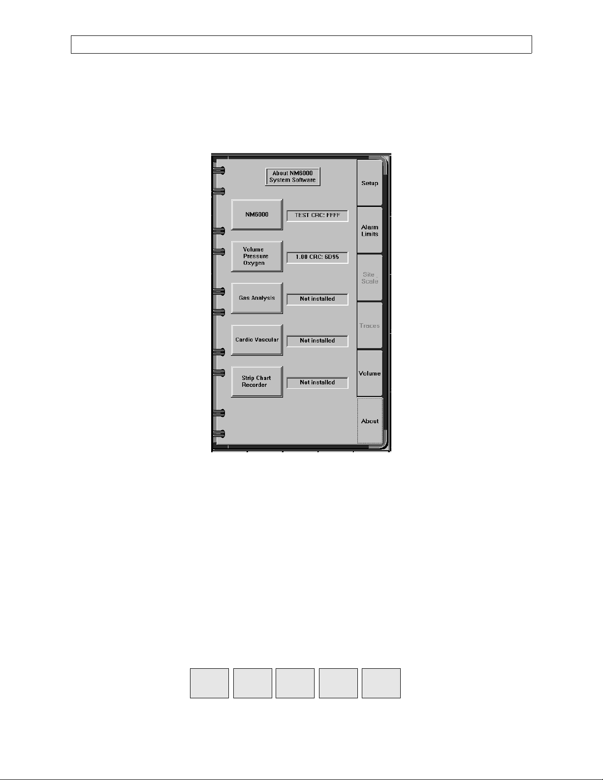
2.1 Accessing the Service Screens
To access the service screens you must first touch the Setup key at the bottom of
the screen to display the setup notebook, then touch the About tab to display the
About page of the setup notebook as shown in Figure 2-1.
RETURN TO THIS MANUAL'S TABLE OF CONTENTS
RETURN TO CD-ROM TABLE OF CONTENTS
NM6000
Figure 2-1. Setup Notebook About Page
On the About page, touch the following keys in this order:
1. Volume, Pressure, Oxygen
2. Gas Analysis
3. NM6000
4. Strip Chart Recorder
In the service mode, the following keys are added at the bottom of the screen:
Exit
Service
Service
Monitors
Service
Config
2-2
Service
Dump
Service
Log
Rev. B
Page 13

RETURN TO THIS MANUAL'S TABLE OF CONTENTS
RETURN TO CD-ROM TABLE OF CONTENTS
NM6000 DIAGNOSTICS (continued)
2.2 Advanced Service Mode
The Advanced service mode allows the service technician to change the NM6000
serial number via the NM6K Configuration Page (described later), to install or
remove software options, update Pod based software and also allows the Pod
Logs and Service Log (described later) to be cleared.
To enter the Advanced service mode, touch the following keys on the About page
of the Setup Notebook in this order:
1. Strip Chart Recorder
2. NM6000
3. Gas Analysis
4. Volume, Pressure, Oxygen
2.3 Service Monitors Notebook
Touch the Service Monitors key at the bottom of the screen to display the
Service Monitors Notebook.
Touching each tab of the service monitors notebook will bring up the
corresponding service screen page, as described in the following paragraphs.
If desired, touch the Exit Service key to return to the monitoring screen.
Rev. L
2-3
Page 14

DIAGNOSTICS (continued)
2.3.1 Oxygen Monitor Service Screen
The Oxygen page of the service monitors notebook is shown on the left
side of Figure 2-2. This page displays current and stored A/D values for
the oxygen cells, date and time of the last O
instructions for performing a zero calibration.
If the O2 zero calibration values stored in the VPO pod are invalid upon
startup, a SERVICE O2 MON advisory is posted, the Service Monitors
Oxygen page will show a blank Last O2 Calibration date, and the
message ZERO CALIBRATION INVALID is displayed on the Service
Monitors Oxygen page as shown on the right side of Figure 2-2. These
three things also occur if a zero calibration is attempted with a current
cell value of less than 230 or greater than 260.
RETURN TO THIS MANUAL'S TABLE OF CONTENTS
RETURN TO CD-ROM TABLE OF CONTENTS
NM6000
zero calibration, and
2
Refer to Section 5 for details on both zero and 21% O
calibrations.
2
Figure 2-2. Service Monitors Notebook, Oxygen Page
2-4
Rev. F
Page 15

RETURN TO THIS MANUAL'S TABLE OF CONTENTS
RETURN TO CD-ROM TABLE OF CONTENTS
NM6000 DIAGNOSTICS (continued)
2.3.2 Pressure Monitor Service Screen
Touch the Pressure tab of the Service Monitors Notebook to display the
pressure monitor service screen shown in Figure 2-3.
This page displays current pressure value, stored zero and span values,
and procedures for performing zero and span calibrations.
Test equipment connections are given in Section 5.
Rev. B
Figure 2-3. Service Monitors Notebook, Pressure Page
2-5
Page 16
DIAGNOSTICS (continued)
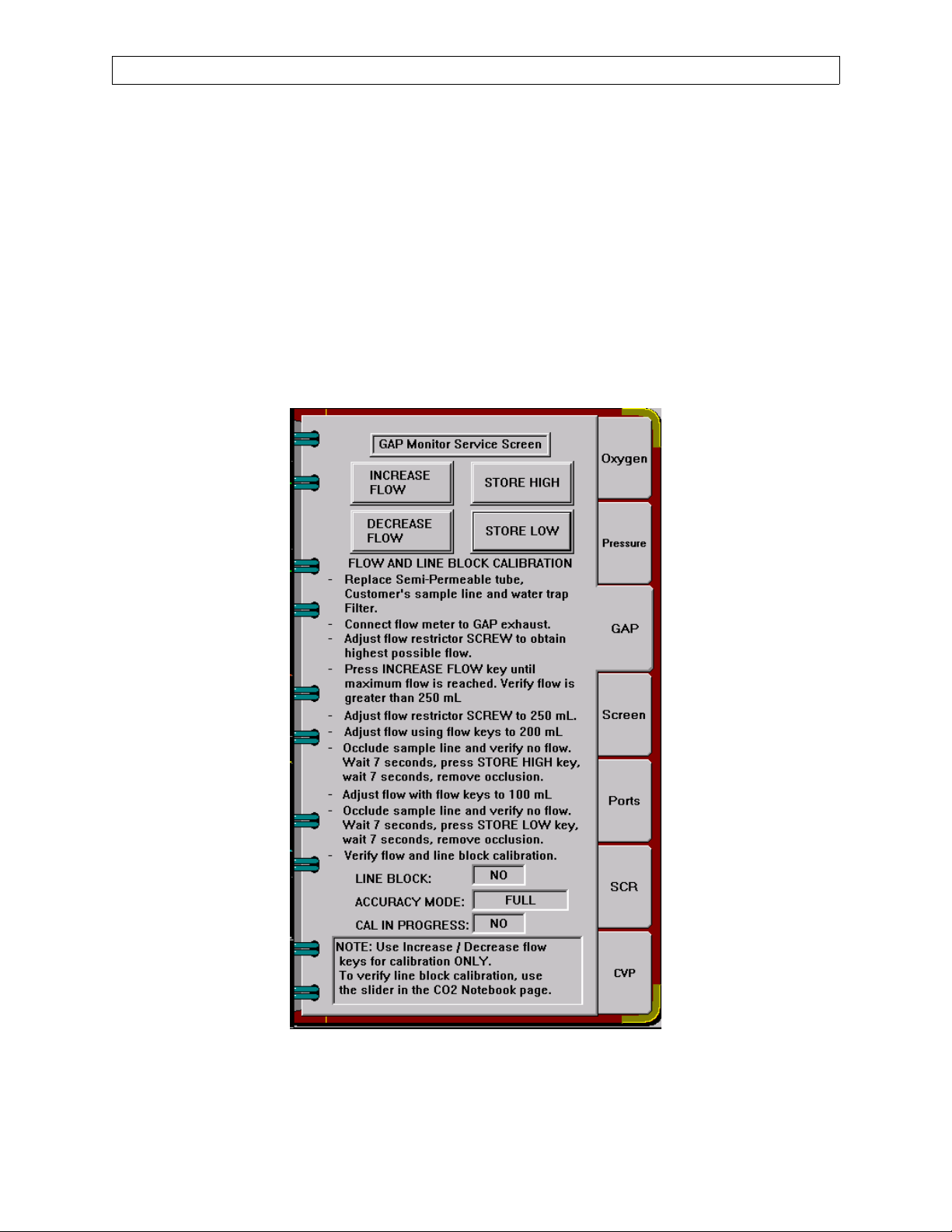
2.3.3 Gas Analyzer Sample Flow Service Screen
Touch the GAP tab of the Service Monitors Notebook to display the flow
monitor service screen shown in Figure 2-4.
This page provides touch keys and procedures for adjusting and storing
the high (200 mL/min.) and low (100 mL/min.) sample line flow rates.
Line block, accuracy mode, and calibration in progress indications are
also provided on this page.
Location of the adjustable flow restrictor for initial flow rate setting, and
test equipment connections are given in Section 5.
RETURN TO THIS MANUAL'S TABLE OF CONTENTS
RETURN TO CD-ROM TABLE OF CONTENTS
NM6000
Figure 2-4. Service Monitors Notebook, GAP Page
2-6
Rev. R
Page 17

RETURN TO THIS MANUAL'S TABLE OF CONTENTS
RETURN TO CD-ROM TABLE OF CONTENTS
NM6000 DIAGNOSTICS (continued)
2.3.4 Screen Functions
Touch the Screen tab of the Service Monitors Notebook to display the
service screen shown in Figure 2-5.
Touch screen calibration is needed whenever a monitor is replaced, or
when picture size or centering is adjusted. This ensures correct
registration of the touch screen coordinates with the picture.
NOTE: An advanced touch screen calibration procedure is needed when
calibration is not possible under the usual procedure.
The Brightness/Contrast and Phase buttons are used to display test
patterns for adjustments on machines with a flat panel display.
Refer to Section 5 for the complete procedures.
Rev. B
Figure 2-5. Service Monitors Notebook, Screen Page
2-7
Page 18

DIAGNOSTICS (continued)
2.3.5 Port Configuration
Touch the Ports tab of the Service Monitors Notebook to display the port
configuration service screen shown in Figure 2-6. On machines with
only one com port (com 2), the screen shown in Figure 2-6A applies.
This page allows com ports 5, 6, 7, and 8 on the machine to be configured
for communication with external devices. Touching each parameter
displayed allows you to cycle through the available settings for the
corresponding port. The selections are:
Baud: 9600, 19200, 38400
Parity: EVEN, ODD, NONE
Stop Bits: 1, 2
Data Bits: 7, 8
Protocol: Vitalink
When the desired settings are displayed, touch the APPLY key to store
the settings.
RETURN TO THIS MANUAL'S TABLE OF CONTENTS
RETURN TO CD-ROM TABLE OF CONTENTS
NM6000
Figure 2-6. Service Monitors Notebook,
Port Configuration Page
2-8
Figure 2-6A. Service Monitors Notebook,
Port Configuration Page,
One Com Port
Rev. B
Page 19
RETURN TO THIS MANUAL'S TABLE OF CONTENTS
RETURN TO CD-ROM TABLE OF CONTENTS
NM6000 DIAGNOSTICS (continued)
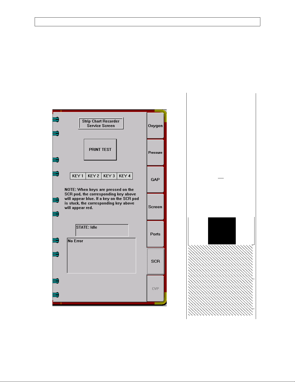
2.3.6 SCR Print Test
Touch the SCR tab on the Service Monitors Notebook to display the Strip
Chart Recorder Service Screen as shown in Figure 2-6B.
Diagnostic functions are provided for keys on the strip chart recorder.
Touching the PRINT TEST button will produce the printer output shown
in Figure 2-6C.
^^^^^^^^^^^^^^^^^^^^^^^^
*** AR42 Ver. 2.05 **
sn ØØØØ429792
ØØ: ↓↓↓↓↓↓↓↓↓↓↓↓↓↓↓↓
1Ø: ↓↓↓↓↓↓↓↓↓↓↓↓↓↓↓↓
2Ø: !”#$%&’()*+,-./
3Ш: Ш123456789:;<=>?
4Ш: @ABCDEFGHIJKLMNO
5Ш: PQRSTUVWXYZ[\]^6Ш: ‘abcdefghijklmno
7Ш: pqrstuvwxyz{|}¯
8Ш: ЗьйвдаезклипомДЕ
9Ш: ЙжЖфцтыъяЦЬ¢£¥.ƒ
AШ: бнуъсСao
BШ: ↓↓↓↓↓↓↓↓↓↓↓↓↓↓↓↓
CØ: ↓↓↓↓↓↓↓↓↓↓↓↓↓↓↓↓
DØ: ↓↓↓↓↓↓↓↓↓↓↓↓↓↓↓↓
EØ: ↓↓↓↓↓↓↓↓↓↓↓↓↓↓↓↓
FØ: ↓↓↓↓↓↓↓↓↓↓↓↓↓↓↓↓
¿↓↓↓↓¡↓↓
Figure 2-6B. Service Monitors Notebook,
SCR Page
Rev. H
2-8A
^^^^^^^^^^^^^^^^^^^^^^^^
Figure 2-6C. Test Print
Page 20

DIAGNOSTICS (continued)
RETURN TO THIS MANUAL'S TABLE OF CONTENTS
RETURN TO CD-ROM TABLE OF CONTENTS
NM6000
This page intentionally left blank
2-8B
Rev. H
Page 21
RETURN TO THIS MANUAL'S TABLE OF CONTENTS
RETURN TO CD-ROM TABLE OF CONTENTS
NM6000 DIAGNOSTICS (continued)
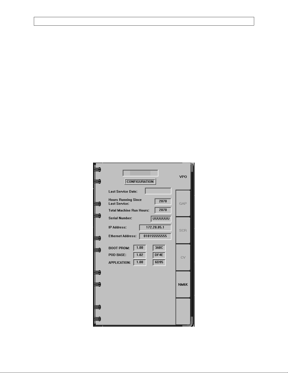
2.4 Service Configuration Notebook
Touch the Service Config key at the bottom of the screen to display the Service
Configuration Notebook shown in Figure 2-7. Tabs are displayed for each pod,
and for the Narkomed 6000. Touching each tab of the service configuration
notebook will bring up the corresponding configuration page, as described in the
following paragraphs. (An Options page is enabled when you are in the
Restricted Service Mode. See Paragraph 2.2A.)
2.4.1 Pod Configuration Pages
The VPO, GAP, SCR and CV pages display the following information for
each pod:
Last Service Date
Hours Running Since Last Service
Total Machine Run Hours
Serial Number
IP Address
Ethernet Address
Identification for Boot Prom, Pod Base Software and Application
VPO
Rev. F
Figure 2-7. Service Configuration Notebook, VPO Page
2-9
Page 22

DIAGNOSTICS (continued)
2.4.2 UPDATE Page
Touching the UPDATE tab of the Service Configuration Notebook will
display the page shown in Figure 2-8.
This page allows the service technician to download images to the pods.
If the information on the update page does not match the image on the
host, this information on the update page appears in red when in the
Advanced service mode. When in Advanced mode, pressing the
appropriate box initiates a download, and the information in the boxes
reflects the state of the download. NOTE: When the key is pressed, the
notebook disappears. Press the Service Config key to refresh the Service
Config Notebook. If not in Advanced mode, pressing the boxes will
display the message: “Enter Advanced Access Mode in order to
download.”
RETURN TO THIS MANUAL'S TABLE OF CONTENTS
RETURN TO CD-ROM TABLE OF CONTENTS
NM6000
Figure 2-8. System Update Download Screen
2-10
Rev. M
Page 23
RETURN TO THIS MANUAL'S TABLE OF CONTENTS
RETURN TO CD-ROM TABLE OF CONTENTS
NM6000 DIAGNOSTICS (continued)
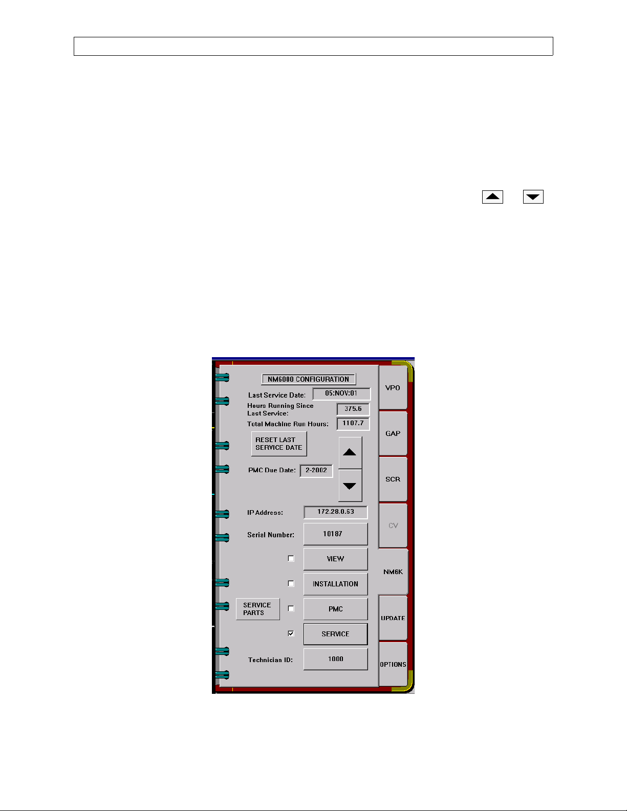
2.4.3 NM6K Configuration Page
Touching the NM6K tab of the Service Configuration Notebook will
display the NM6000 configuration page shown in Figure 2-9. This page
displays the Last Service Date, Hours Running Since Last Service, and
Total Machine Run Hours. Touching the RESET LAST SERVICE DATE
key will reset the displayed last service date to the current date for the
machine and for all connected pods.
This page also displays the next PMS Due Date. Touch the or
keys to set the desired date.
A Service Parts listing (described later) is also accessed through this
screen.
Should the machine’s processor be replaced, the machine serial number
needs to be entered. You can only do this while in the Advanced service
mode: Press the Serial Number button, and type the new number with
the touch keys that appear on the page. Press the Serial Number button
again to enter the number. This event will be recorded in the Service
Log.
Rev. R
Figure 2-9. Service Configuration Notebook, NM6K Page
2-11
Page 24

DIAGNOSTICS (continued)
2.4.4 Service Parts Screens
Press the SERVICE PARTS button on the NM6K Configuration Page to
view the service parts list as shown in Figure 2-10. If you are in the
PMS mode (press the Preventive Maintenance button and enter a valid
technician ID), you will be able to modify the list. If you are not in the
PMS mode and attempt to modify the list, you will be prompted to “Enter
Preventive Maintenance in order to change part information.”
In the user access mode Several keys appear on the Service Parts screen;
their function are as follows:
PREVIOUS: Move to the entry above the current selection.
NEXT: Move to the entry below the current selection
REPLACE: Brings up a dialog box asking if the selected part
SERIAL NUMBER: Brings up a keyboard for the user to enter a serial
RETURN TO THIS MANUAL'S TABLE OF CONTENTS
RETURN TO CD-ROM TABLE OF CONTENTS
NM6000
was replaced.
number
OK: Saves all information, and returns display to the
NM6K configuration page. Any changes made are
recorded in the service log.
CANCEL: Any changes made to the list are not saved, and
display returns to the NM6K configuration page.
In the Advanced access mode, the following additional keys are
displayed:
FACTORY DEFAULTS: Changes the list to factory defaults for part
numbers, descriptions, quantity and schedule.
SET DATES: Brings up dialog box that allows user to set
dates for the selected part, or to clear all dates.
PART NUMBER: Brings up a keyboard that allows user to
change a part number.
When the Service Parts screen is entered for the first time, all dates and
serial numbers are blank except for pod serial numbers. You can select a
part by using the Previous or Next keys, or by pressing the desired row
on the screen under one of the date columns.
When you press the Replace key, the screen appears as shown in Figure
2-11.
2-12
Rev. B
Page 25

RETURN TO THIS MANUAL'S TABLE OF CONTENTS
RETURN TO CD-ROM TABLE OF CONTENTS
NM6000 DIAGNOSTICS (continued)
Figure 2-10. Service Parts Screen
Figure 2-11. Service Parts Replacement Query
Rev. B
If you press the No button, the dates are not modified.
If you press the Yes button the current date will be entered under Last
Date for the item selected, and the Next Date will be calculated using the
schedule. If there is no replacement schedule, the Next Date will remain
blank.
2-13
Page 26

DIAGNOSTICS (continued)
If you press any row under the Schedule column, a dialog box will appear
asking if you replaced all parts with the same schedule. If you answer
No, the dates are not modified. If you answer Yes, all dates for parts with
the same schedule can be updated. All blank Next Dates will be modified
assuming that this is the first replacement. If the current date is in the
same month or later than the Next Date, that row will appear in red.
If you press any row in red under the Description or Quantity column, a
dialog box will appear asking if you replaced all parts that are due. If you
answer Yes, the Last Date and Next Date will be updated for all parts
that are due to be replaced.
Pressing the Set Dates key will bring up the screen shown in Figure 2-
12.
RETURN TO THIS MANUAL'S TABLE OF CONTENTS
RETURN TO CD-ROM TABLE OF CONTENTS
NM6000
4115864
Figure 2-12. Service Parts Set Dates Screen
If you press the Clear Selected Date key, the Last Date and Next Date for
the selected part will be cleared.
If you press the Clear All Dates key, all information in the Last Date and
Next Date columns will be cleared.
If you press the Set Selected Last Date key, The Last Date for the
selected part will be changed to the month and year shown on this
window.
2-14
Rev. E
Page 27

RETURN TO THIS MANUAL'S TABLE OF CONTENTS
RETURN TO CD-ROM TABLE OF CONTENTS
NM6000 DIAGNOSTICS (continued)
If you press the Set All Next Dates Based on Selected Date and Schedule
key, all the information in the Next Date column will be calculated based
on the selected month and year. The selected month and year can be
changed using the arrow keys.
If you press the Set Selected Next Date key, the Next Date for the
selected part will be changed to the month and year selected.
Pressing the SAVE key will update the parts list display. If you press the
QUIT key, none of the changes made using this window will be saved.
Rev. B
2-15
Page 28

DIAGNOSTICS (continued)
2.4.5 NM6000 Software Options Screen
Touching the Options tab in the Service Configuration Notebook will
display the page shown in Figure 2-8A.
This page allows the service technician to enable or disable software
controlled options when in advanced service menu. This page can not be
selected in User Access Service Mode.
NOTE: ‘Air Only Mode’ and Templates & Sounds options also require
RETURN TO THIS MANUAL'S TABLE OF CONTENTS
RETURN TO CD-ROM TABLE OF CONTENTS
NM6000
keyloks to enable these features. If application software is
version 2.06, Low Flow Wizard also requires a Keylok to enable
this feature.
Figure 2-12 A. Software Options Screen
2-15A
Rev. R
Page 29

RETURN TO THIS MANUAL'S TABLE OF CONTENTS
RETURN TO CD-ROM TABLE OF CONTENTS
NM6000 DIAGNOSTICS (continued)
This page intentionally left blank
Rev. L
2-15B
Page 30
DIAGNOSTICS (continued)
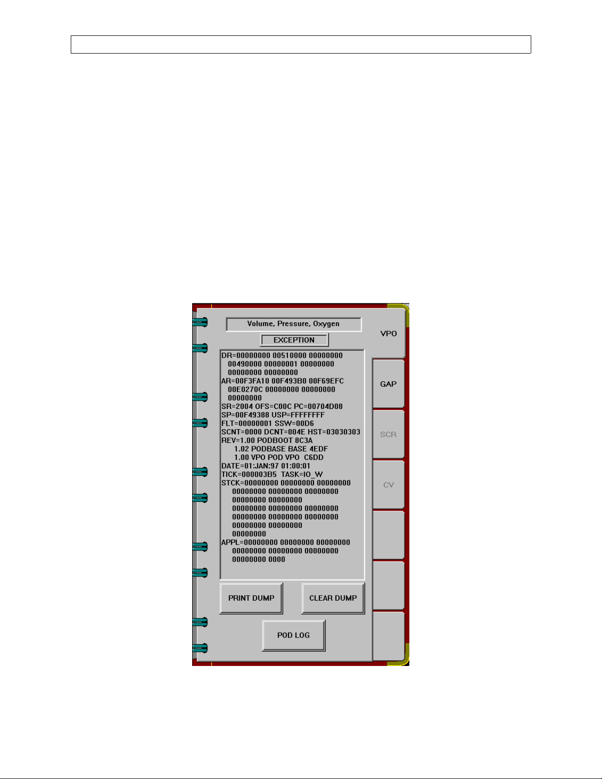
2.5 Service Dump Notebook
Touch the Service Dump key at the bottom of the screen to display the Service
Dump Notebook shown in Figure 2-13. Tabs are displayed for each pod, and for
the Narkomed 6000. Touching each tab of the service dump notebook will
display dump data for the corresponding page.
Touch the PRINT DUMP key to print out the data on the strip chart recorder. If
there is no strip chart recorder on the machine, then touching the PRINT
DUMP key will write the data to a file on the hard drive of the NM6000.
To clear the service dump, enter the advanced service menu, then touch the
CLEAR DUMP key to clear the service dump data for that page.
Touching the POD LOG button causes the pod log screen to be displayed in the
same area as the service log. See next page.
RETURN TO THIS MANUAL'S TABLE OF CONTENTS
RETURN TO CD-ROM TABLE OF CONTENTS
NM6000
Figure 2-13. Service Dump Notebook
2-16
Rev. L
Page 31

RETURN TO THIS MANUAL'S TABLE OF CONTENTS
RETURN TO CD-ROM TABLE OF CONTENTS
NM6000 DIAGNOSTICS (continued)
2.5.1 Pod Log Screens
While the NM6000 is obtaining the service log, a progress bar is displayed
and an ABORT REFRESH button is enabled. Pressing this button will
cause the NM6000 to stop acquiring the service log from the pod.
Figure 2-13A. Pod log download screen
When all entries are obtained (or refresh is aborted), the ABORT
REFRESH button becomes the REFRESH BUTTON, and the SAVE,
PRINT, CLEAR and OK buttons appear.
Rev. F
Figure 2-13B. Pod log screen
2-16A
Page 32

DIAGNOSTICS (continued)
Pressing the REFRESH button will cause the NM6000 to obtain the log from
the pod again. When the SAVE button is pressed, the pod service log is saved to
a file according to pod type:
GAP: c:\nad\datfiles\podlog_gap.txt VPO: c:\nad\datfiles\podlog_vpo.txt
The pod service log is saved as an ASCII file with a header followed by service
log entries each on a separate line. The header contains the type of pod, date
and time log was saved, pod serial number, version and CRC for the BOOT
PROM, PBS and application, NM6000 serial number, version and CRC. Each
log entry contains the date and time, parameter value, and text:
SERVICE POD LOG FOR THE VPO POD
DATE: 9-22-1999 TIME: 10:48:23
POD SERIAL NUMBER: NNNNNNNN
BOOT PROM VERSION: 1.01 CRC: 7295
POD BASE VERSION: 1.02 CRC: 4EDF
APPLICATION VERSION: DEV1 CRC: 8D00
NM6000 SERIAL NUMBER: 145
NM6000 VERSION: 0.0 CRC: FFFF
RETURN TO THIS MANUAL'S TABLE OF CONTENTS
RETURN TO CD-ROM TABLE OF CONTENTS
NM6000
--------------------------------------------------
09-22-99 10:36 007C8D4C PB01 System time set
09-22-99 10:14 00F00104 VP42 O2 CAL zero
09-22-99 10:14 08BD09E9 VP42 O2 CAL gain
09-22-99 10:07 00000000 VP44 Sensor Disconnect
The CLEAR button is enabled when you are in the Advanced Access mode.
Pressing this button clears the pod log. Pressing the OK button removes the pod
service log screen. While the pod service log is displayed, the soft keys and
numeric boxes are disabled. If an entry under the ID column is pressed, the
following dialog box is displayed:
Do you want to display events with ID VPXX?
The VPxx in the title corresponds to the ID of the entry that was pressed. If YES
is pressed, the displayed service log contains only entries with the selected ID. If
an entry is pressed under any column other than ID, that entry is displayed in
blue. The entry is then marked with * in the saved text.
2-16B
Rev. F
Page 33

RETURN TO THIS MANUAL'S TABLE OF CONTENTS
RETURN TO CD-ROM TABLE OF CONTENTS
NM6000 DIAGNOSTICS (continued)
2.6 Service Log
Press the Service Log key at the bottom of the screen to display the service log.
Initially, a blank page appears as shown in Figure 2-14.
Figure 2-14. Service Log Initial Screen
Press the Refresh button to bring up the service log as shown in Figure 2-15.
Rev. R
Figure 2-15. Service Log
2-17
Page 34

DIAGNOSTICS (continued)
RETURN TO THIS MANUAL'S TABLE OF CONTENTS
RETURN TO CD-ROM TABLE OF CONTENTS
NM6000
Figure 2-15A. Data Log Screen
Figure 2-15B. Alarm Log Screen
2-18
Rev. R
Page 35

RETURN TO THIS MANUAL'S TABLE OF CONTENTS
RETURN TO CD-ROM TABLE OF CONTENTS
NM6000 DIAGNOSTICS (continued)
Error events are displayed in red, warning events appear in yellow, and
information events are in white. Pressing the Save button will save the service
log to the hard drive for later retrieval.
Several Filter keys are displayed with the service log. When the Filter Date key
is pressed, a filter date window appears which allows you to select only the
events by date that you want to display. Press the OK button to display those
events.
Pressing the Filter Source and Category button brings up a window that allows
you to select the source (SysOneMgr, etc.) and display any or all categories of
error, warnings or information events. Press the OK button to display those
events. If you press the RESET button on this window, all sources and
categories are displayed.
Pressing the Filter ID button brings up a window that allows you to display
events by ID number. Press the ALL button; it then becomes blank. Enter the
desired ID using the number buttons. That number will then appear on the
blank button. Press the OK button to display those selected events.
NOTE: the Clear key is active only if you are in the Advanced service mode.
When you press this key, a dialog box “Do you really want to clear the service
log?” appears. If you press the Yes button, the service log will be cleared.
Information contained in each type log may be viewed using various filters:
Selecting a Date filter allows the log to be sorted by first or last event, or to be
filtered by specified date ranges. See Figure 2-15C.
Figure 2-15C. Alarm - Filter Date
Rev. R
2-18A
Page 36

DIAGNOSTICS (continued)
Selecting Filter Event ID and entering a specific event ID will display only the
entries that match the selected ID. See Figure 15D.
Figure 2-15D. Alarm - Filter Event ID
RETURN TO THIS MANUAL'S TABLE OF CONTENTS
RETURN TO CD-ROM TABLE OF CONTENTS
NM6000
Selecting Filter Source, Category and Type provides numerous filters allowing
for customized views of entries that meet several filtering criteria.
See Figure 2-15E.
Figure 2-15E. Alarm - Filter Source
2-18B
Rev. R
Page 37

RETURN TO THIS MANUAL'S TABLE OF CONTENTS
RETURN TO CD-ROM TABLE OF CONTENTS
NM6000 DIAGNOSTICS (continued)
2.6.1 Save Service Log window
When the LOCAL SAVE button is pressed, all logs are saved to the file
c:\nad\datfiles\slog.txt. All buttons on this window are disabled while
the service log is being saved.
Figure 2-15F. Save Service Log window
When the Computer button is pressed, a software keyboard is displayed
that allows you to change the computer name. You can also select from
the last five computer names entered. The default computer name is
SRVLAP.
When the Folder button is pressed, a software keyboard is displayed that
allows you to change the folder name. You can also select from the last
five folder names entered. The default folder name is NAD Software.
CAUTION: Before connecting an external computer to the Narkomed
6000, verify the computer is running a virus protection application set to
scan all files and is enabled. You must also verify that the definition files
and scan engines are of current vintage.
When the REMOTE SAVE button is pressed, all buttons on the SAVE
SERVICE LOG window are disabled. If the NM6000 is unable to find the
remote computer, an error message is displayed, the buttons are enabled,
and no further processing occurs. If the remote computer is found, the
NM6000 attempts to create a directory in the format \\computer
name\folder name\nm6k\SNXXXXXXXX. The NM6000 will then copy
all the files from the c:\nad\datfiles directory and the NT event file
APPEVENT.EVT to the remote location. The NM6000 will then save the
current service log to the remote location using the name
slog_date_time.txt where the date and time will be replaced with the
current date and time. If the NM6000 is unable to copy the files, an error
message is displayed and the buttons are enabled.If the service log is
successfully saved, a message that contains the path and name of the
saved service log will be displayed and the buttons will be enabled.
Rev. R
The saved service log is an ASCII text file in the line format
date time~source name of event~category~event ID~event
type~description~data.
Each line is a separate event log entry. Most entries will contain no data.
2-18C
Page 38

DIAGNOSTICS (continued)
2.6A Service Log Entry Detail
Software Version 1.05 adds the following Service Log Entry Detail window. If a
service log entry is pressed while the log keys are enabled, this window is
displayed, showing detailed information about the currently selected event. The
selected event will be highlighted in blue in the event log. A box on this window
displays the following:
ERROR in red for error events
WARNING in yellow for warning events
INFORMATION in white for informational events
RETURN TO THIS MANUAL'S TABLE OF CONTENTS
RETURN TO CD-ROM TABLE OF CONTENTS
NM6000
Figure 2-15G. Service Log Entry Detail window
Pressing the Previous button causes the previous event to be higlighted in blue
on the service log, and the information for the previous event is displayed in the
Service Log Entry Detail window. The last selected entry returns to its
appropriate color. Pressing the Previous button for the most recent entry causes
no changes.
Pressing the Next button causes the next event to be highlighted in blue on the
service log, and the information for the next event is displayed in the Service
Log Entry Detail window. The last selected entry returns to its appropriate
color. Pressing the Next button for the oldest entry causes no changes.
Pressing the Close button removes the Service Log Entry Detail window, and
the last selected entry in the service log returns to its appropriate color.
2-18D
Rev. R
Page 39

RETURN TO THIS MANUAL'S TABLE OF CONTENTS
RETURN TO CD-ROM TABLE OF CONTENTS
NM6000 DIAGNOSTICS (continued)
2.7 NM6000 Event Log Transfer Using Service Laptop with Windows 95, 98 or Me
The following procedure allows the Narkomed 6000’s event log and POD logs to be
downloaded to a service laptop using either Windows 95 or 98 operating system. The
logs are saved to the laptop’s hard drive NM6K folder for subsequent analysis. (Refer to
Section 2.7A if using a service laptop with Windows NT operating system.) The
following items are needed:
--Service laptop computer, IBM PC or compatible
with: Type II or larger PCMCIA slots
500 MB hard drive minimum
Windows 95 or 98
Etherlink card configured to share files
--Vitalan cable P/N 4113989-001
CAUTION: Before connecting an external computer to the Narkomed 6000, verify the
computer is running a virus protection application set to scan all files and is enabled.
You must also verify that the definition files and scan engines are of current vintage.
2.7.1 Configure the laptop as shown in Figure 2-16.
2.7.2 With the Narkomed 6000 System Power switch at STANDBY and the laptop
computer Off, connect the laptop’s etherlink cable to any Vitalbus port on the
Hub. See Figure 2-17.
2.7.3 Power up the laptop computer and the NM6000. Press the Divan Standby key to
cancel the ventilator self-test, and wait for the power up diagnostics to finish.
Verify the green LED on the Lancard cable is illuminated. (If the laptop
computer prompts for a password, select Cancel.)
2.7.4 Press the Setup key and select the About tab on the About System Software
notebook. Enter the primary service menu code and select OK on the Service
Mode screen to enter the USER ACCESS service mode.
2.7.5 Under the Service Mode screen select the NM6000 tab and enter the advanced
service code to enter the ADVANCED ACCESS mode.
2.7.6 Press the Service Config key and select the SERVICE key. Using the NM6000
on-screen keyboard, enter your service ID number then press OK.
2.7.7 Press the Service Log key to call up the service event log.
2.7.8 Press the Refresh key to refresh the logs. During this activity the Save key text
will turn gray. When the Save key turns black again, press the Save key to bring
up the SAVE SERVICE LOG dialog.
2.7.9 If the laptop computer name is not SRVLAP or the desired folder is not NAD
Software, touch these keys to make the required edits.
Rev. N
2.7.10 Press the REMOTE SAVE button. If the NM6000 is unable to find the remote
computer, an error message is displayed. If the remote computer is found, the
NM6000 attempts to create a directory in the format \\computer name
‘SRVLAP’\folder name ‘NAD Software’\nm6k\SNXXXXXXXX.
2-19
Page 40

DIAGNOSTICS (continued)
RETURN TO THIS MANUAL'S TABLE OF CONTENTS
RETURN TO CD-ROM TABLE OF CONTENTS
NM6000
1. Turn on the laptop if necessary
Install the Drivers
2. Ensure that the Ethernet card and driver are
installed.
Set the Computer Name and IP Address
3. Select “Start->Programs->Windows Explorer”
from the task bar.
4. Right click “Network Neighborhood” or My
Network Places” if using Windows Me. If there
is not a selection for “Network Neighborhood” or
“My Network Places”, select StartàSettingsà
Control PanelàNetwork. Launch the install
wizard to load “Client for Microsoft Networks.”
5. Select the PROPERTIES button.
6. Select the “Identification” tab.
7. Enter the following data (as necessary):
Computer Name: srvlap
Work Group: Service
8. Select the “Configuration” tab.
9. Select the “TCP/IP” item (looks like an electrical
plug).
10. Press the “Properties” button.
11. Select the “IP Address” tab.
21. Ensure that the directory “NAD
Software”\NM6K exists on the C:\ drive.
22. Right click the “NAD Software” directory.
23. Select the “Sharing” menu item.
24. Select the “Sharing” tab.
25. Select the “Share As...” radio button.
26. Ensure that “NAD Software appears as the
share name.
27. Select the “Full” Access type radio button.
28. Press APPLY, then OK.
Turn off the Dial-Up modem (if applicable)
29. Right click “My Computer:”
30. Select the Properties menu item.
31. Select the “Device Manager” tab.
32. Expand “Network Adapters” by clicking the “+”
box on the line.
33. Select the Dial-up adapter.
34. Select the PROPERTIES button.
35. Ensure that “Disable in this hardware profile”
is checked.
12. Select the “Specify an IP address” radio button.
13. Set the following fields:
IP Address: 172.28.0.130
Subnet Mask: 255.255.0.0
14. Press OK.
Share the directories
15. Select the “Access Control” tab.
16. Select the “Share-level access control” radio
button.
17. Select the “Configuration” tab.
18. Click on “File and Print Sharing” button.
19. Select the “I want to be able to give o thers access
to my files” item.
20. Press OK, and press OK again to exit the
Network dialog box.
Figure 2-16. Configuring the Windows 95, 98 Laptop
36. Press OK.
Clean up and Reboot
37. Close all open windows.
38. Select “Start->Shut Down” from the task bar.
39. In the “Shut Down Windows” dialog box, select
“Restart the Computer?”
40. Press “Y
system to reboot.
es”; allow several minutes for the
2-20
Rev. N
Page 41

RETURN TO THIS MANUAL'S TABLE OF CONTENTS
RETURN TO CD-ROM TABLE OF CONTENTS
NM6000 DIAGNOSTICS (continued)
SV00368
Rev. K
Figure 2-17. Connections for Windows 95, 98 Event Log Transfer
2-21
Page 42

DIAGNOSTICS (continued)
2.7.11 After successful completion of an Event Log transfer, the file will be
located on the laptop computer as shown in Figure 2-18.
RETURN TO THIS MANUAL'S TABLE OF CONTENTS
RETURN TO CD-ROM TABLE OF CONTENTS
NM6000
Figure 2-18. Laptop Computer File Example
2.7.12 Verify the fourteen files transferred properly to the laptopo and forward
the files to DMI’s Technical Support Department for further analysis.
NOTE: The Appevent.evt, Slog.txt, and Slog_xxxxxxxx_xxxxxx.txt files
must each contain at least 100KB of data.
2-22
Rev. K
Page 43

RETURN TO THIS MANUAL'S TABLE OF CONTENTS
RETURN TO CD-ROM TABLE OF CONTENTS
NM6000 DIAGNOSTICS (continued)
Figure 2-19. Deleted
Figure 2-20. Deleted
Figure 2-21. Deleted
Rev. K
2-23
Page 44

RETURN TO THIS MANUAL'S TABLE OF CONTENTS
RETURN TO CD-ROM TABLE OF CONTENTS
DIAGNOSTICS (continued)
2.7A NM6000 Event Log Transfer Using Service Laptop with Windows NT
The following procedure allows the Narkomed 6000’s event log and POD logs to be
downloaded to a service laptop using Windows NT operating system. The logs are saved
to the laptop’s hard drive NM6K folder for subsequent analysis. (Refer to Section 2.7 if
using a service laptop with Windows 95 or 98 operating system.) The following items are
needed:
--Service laptop computer, IBM PC or compatible
with: Type II or larger PCMCIA slots
500 MB hard drive minimum
Windows NT
Etherlink card configured to share files
--Vitalan cable P/N 4113989-002
CAUTION: Before connecting an external computer to the Narkomed 6000, verify the
computer is running a virus protection application set to scan all files and is enabled.
You must also verify that the definition files and scan engines are of current vintage.
NM6000
2.7A.1 With the Narkomed 6000 System Power switch set to STANDBY and the laptop
computer Off, connect the laptop’s etherlink cable to any Vitalbus port on the
Hub as shown in Figure 2-21A.
SV00368
Figure 2-21A. Connections for Windows NT Event Log Transfer
2-23A
Rev. N
Page 45

RETURN TO THIS MANUAL'S TABLE OF CONTENTS
RETURN TO CD-ROM TABLE OF CONTENTS
NM6000 DIAGNOSTICS (continued)
2.7A.2 Power up the laptop computer and the NM6000. Press the Divan
Standby key to cancel the ventilator self test. When prompted for a
network password, enter “password” and wait for the power up
diagnostics to finish.
Verify the network workgroup. If unknown, this information can be
found as follows: From the Windows NT desktop: right click on Network
Neighborhood; select Priorities, select the Identification tab. The
workgroup will be listed in one of the text boxes displayed. If the
workgroup is not “Goldisk”, use procedure 2.7B. It is also highly
recommended that you contact your information systems admistrator to
make the necessary changes to the laptop. (To work correctly, workgroup
must be “Goldisk”, administrator password must be “NAD123NAD123”)
2.7A.3 Verify the computer name for the laptop; ie: SRVLAP028. See Figure 2-
21B. If unknown, this information can be found as follows:
From the Windows NT Desktop:
-- Right-click on Network Neighborhood
-- Select Properties
-- Select the Identification tab
-- The computer name will be listed in one of the text boxes displayed
Rev. L
Figure 2-21B. Computer Name Identification Screen
2-23B
Page 46

DIAGNOSTICS (continued)
2.7A.4 Verify the laptop TCP/IP address is updated to communicate with the
NM6000. If unknown, this information can be found as follows:
-- From the Network dialog in Figure 2-21B, click on the Protocols tab.
--A dialog window shall appear as in Figure 2-21C
RETURN TO THIS MANUAL'S TABLE OF CONTENTS
RETURN TO CD-ROM TABLE OF CONTENTS
NM6000
Figure 2-21C. Protocols Tab
-- Click once on the TCP/IP Protocol entry in the list of Network
Protocols.
-- Click the P
roperties button
-- A dialog shall appear as in Figure 2-21D.
--Using the drop down arrow, select the correct Ethernet adapter.
2-23C
Rev. L
Page 47

RETURN TO THIS MANUAL'S TABLE OF CONTENTS
RETURN TO CD-ROM TABLE OF CONTENTS
NM6000 DIAGNOSTICS (continued)
Rev. K
Figure 2-21D. TCP/IP Properties
-- Select S
pecify an IP address radio button
-- Enter the above shown I
address numbers, use the space bar to advance to the third and fourth
sets.)
-- Enter the above shown Su
-- Select OK to close the TCP/IP Properties dialog window
NOTE: If the MS loop adapter interferes with the proper operation of
the TCP/IP adapter, contact your IS administrator.
-- Select OK to close the Network dialog window
-- Shut down and restart the laptop computer for the new Network
settings to take effect. (When prompted for a password, enter
“password”)
2-23D
P Address (after entering the second set of IP
bnet Mask
Page 48

DIAGNOSTICS (continued)
2.7A.5 Verify the laptop file folders are configured to share with the NM6000. If
unknown, this information can be found as follows:
-- Right-click the Start key
-- Select Explorer
-- At the (C:) select the NAD Software folder (with a hand under it). If
none is present, create it:
F
ile...New...Folder, name it NAD Software
-- If a hand was not under the NAD Software folder, modify it:
Right-click (ALT + ENTER) Sharing, select Shared As,
Permission, Type, Full Control, OK, Apply, OK
You should now see a hand under the NAD Software folder as shown in Figure
2-21E
RETURN TO THIS MANUAL'S TABLE OF CONTENTS
RETURN TO CD-ROM TABLE OF CONTENTS
NM6000
Figure 2-21E. NAD Software Folder
-- Select NM6K folder. If none is present, create it:
Select NAD Software, File...New...Folder, name it NM6K
2-23E
Rev. K
Page 49

RETURN TO THIS MANUAL'S TABLE OF CONTENTS
RETURN TO CD-ROM TABLE OF CONTENTS
NM6000 DIAGNOSTICS (continued)
2.7A.6 On the NM6000, press the Setup key and select the About tab on the
About SystemSoftware notebook. Enter the primary service menu code
and select OK on the Service Mode screen to enter the USER ACCESS
service mode.
2.7A.7 Under the Service Mode screen select the NM6000 tab and enter the
advanced service code to enter the ADVANCED ACCESS mode.
2.7A.8 Press the Service Config key and select the SERVICE key. Using the
NM6000 on-screen keyboard, enter your service ID number, then press
OK.
2.7A.9 Press the Service Log key to call up the service event log.
2.7A.10Press the Refresh key to refresh the logs. During this activity the Save
key text will turn gray. When the Save key text turns black again, press
the Save key to call up the SAVE SERVICE LOG dialog.
2.7A.11 If the Laptop computer name is not SRVLAP028 or the desired folder is
not NAD Software, touch these keys and make the required edits.
2.7A.12Press the REMOTE SAVE button. If the NM6000 is unable to find the
remote computer, an error message is displayed. If the remote computer
is found, the NM6000 attempts to create a directory in the format
\\computer name’SRVLAP’\folder name ‘NAD
Software’\nm6k\SNXXXXXXXX. (The S/N listing is derived from the
NM6000 CONFIGURATION page.)
Rev. K
2-23F
Page 50

DIAGNOSTICS (continued)
2.7A.13After successful completion of an Event Log transfer, the file will be
located on the laptop computer as shown in Figure 2-18.
.
RETURN TO THIS MANUAL'S TABLE OF CONTENTS
RETURN TO CD-ROM TABLE OF CONTENTS
NM6000
Figure 2-21F. Laptop Computer File Example
2.7A.14Verify the fourteen files transferred properly to the laptopo and forward
the files to DMI’s Technical Support Department for further analysis.
NOTE: The Appevent.evt, Slog.txt, and Slog_xxxxxxxx_xxxxxx.txt files
must each contain at least 100KB of data.
2-23G
Rev. K
Page 51

RETURN TO THIS MANUAL'S TABLE OF CONTENTS
RETURN TO CD-ROM TABLE OF CONTENTS
NM6000 DIAGNOSTICS (continued)
2.7B. Event Log Transfer: Alternate Procedure
2.7B.1 Verify the computer name of the laptop, ie: SRVLAP028. See Figure 2-
21G. If unknown, this information can be found as follows:
From the Windows NT Desktop:
-- Right-click on Network Neighborhood
-- Select Properties
-- Select the Identification tab
-- The computer name will be listed in one of the text boxes displayed
Rev. L
Figure 2-21G. Computer Name Identification Screen
2.7B.2 Update the TCP/IP address to communicate with the NM6000.
-- From the Network dialog in Figure 2-21G, click on the Protocols tab.
-- A dialog window shall appear as in Figure 2-21H.
2-23H
Page 52

DIAGNOSTICS (continued)
RETURN TO THIS MANUAL'S TABLE OF CONTENTS
RETURN TO CD-ROM TABLE OF CONTENTS
NM6000
Figure 2-21H. Protocols Tab
-- Click once on the TCP/IP Protocol entry in the list of Network
Protocols.
-- Click the P
roperties button
-- A dialog shall appear as in Figure 2-21J.
2-23J
Rev. L
Page 53

RETURN TO THIS MANUAL'S TABLE OF CONTENTS
RETURN TO CD-ROM TABLE OF CONTENTS
NM6000 DIAGNOSTICS (continued)
Rev. L
Figure 2-21J. TCP/IP Properties
-- Select S
pecify an IP address radio button
-- Enter the above shown I
address numbers, use the space bar to advance to the third and fourth
sets.)
-- Enter the above shown Su
-- Select OK to close the TCP/IP Properties dialog window
-- Select OK to close the Network dialog window
-- Shut down and restart the laptop computer for the new Network
settings to take effect.
2-23K
P Address (after entering the second set of IP
bnet Mask
Page 54

DIAGNOSTICS (continued)
2.7B.3 Configuring the Laptop:
On the Laptop computer:
-- Right-click the Start key
-- Select Explorer
-- At the (C:) select NAD Software folder (with a hand under it). If none is
present, create it:
ile...New...Folder, name it NAD Software
F
-- If a hand was not under the NAD Software folder, modify it:
Right-click (ALT + ENTER) Sharing, select Shared As,
Permission, Type, Full Control, Apply, OK
-- Select NM6K folder. If none is present, create it:
File...New...Folder, name it NM6K
-- Select the Event Log folder. If none is present, create it:
RETURN TO THIS MANUAL'S TABLE OF CONTENTS
RETURN TO CD-ROM TABLE OF CONTENTS
NM6000
File...New...Folder, name it Event Log
You should now see a hand under the NAD Software folder as shown in Figure
2-21K.
Figure 2-21K. Shared Event Folder
2-23L
Rev. L
Page 55

RETURN TO THIS MANUAL'S TABLE OF CONTENTS
RETURN TO CD-ROM TABLE OF CONTENTS
NM6000 DIAGNOSTICS (continued)
2.7B.4 Turn the Narkomed 6000 System Power switch to ON. Allow the system
to complete its power up self diagnostic tests, then press Ctrl+F9,
Alt+F9, and Ctrl-ESC on the NM6K keyboard to call up the Start menu.
NOTE: Use the Arrow and Tab keys to navigate through the selections.
-- Select Start...F
-- L
ook in: My Computer
ind File or Folders
-- In the Named list: select AppEvent.evt. If the dropdown window is
empty, type in AppEvent.evt. See Figure 2-21L.
-- Select Find Now
-- Verify that the file is highlighted and press Ctrl+C to copy the file.
-- Click on the X at the top right to close the Find window.
Figure 2-21L. Find AppEvent.evt Screen
-- Press the Window key or Ctrl+Esc to bring up the task bar.
-- Type R for R
-- In the O
dropdown window is empty, type in \\SRVLAP
un
pen list: select \\SRVLAP028, then select OK. If the
028.
NOTE: If the computer name is not SRVLAP028, type in \\ followed by
the appropriate name as previously identified.
-- Select OK
Figure 2-21M. Run Box
Rev. L
2-23M
Page 56

DIAGNOSTICS (continued)
2.7B.5 A Network Password window should soon appear indicating an
incorrect user name or password. This is normal. Enter the computer’s
name (SRVLAP028) in the C
portion of this listed field and enter the word “password” in the
assword field. Press the Enter key.
P
NOTE: If the host NM6000 cannot locate the networked laptop computer,
recheck the laptop’s configuration setting.
RETURN TO THIS MANUAL'S TABLE OF CONTENTS
RETURN TO CD-ROM TABLE OF CONTENTS
NM6000
onnect As: field by removing the “\\”
Figure 2-21N. Network Password
2.7B.6 A window should appear on the NM6000 showing all shared folders on
the laptop, as identified with a hand under the folder. If no shared
folders appear, recheck the selections made in the Configuring the
Laptop section.
-- Open the EventLog Folder (SRVLAP028\NAD
Software\NM6K\Eventlog)
-- Press CTRL+V to paste the file to the laptop.
-- Verify that the AppEvent.evt file appears on the NM6000 screen.
-- Select the AppEvent.evt file.
-- Select F
ile, Rename, move the cursor to the left of the file name and
key in the 5-digit NM6000 serial number followed by a space.
-- Press Enter
-- Close all open windows
Verify the file transferred properly to the laptop, and forward the file to DMI’s
technical support department.
NOTE: The Appevent.evt file must contain at least 100 kB of data.
2-23N
Rev. L
Page 57

RETURN TO THIS MANUAL'S TABLE OF CONTENTS
RETURN TO CD-ROM TABLE OF CONTENTS
NM6000 DIAGNOSTICS (continued)
2.7B.7 Restoring your original Laptop Computer’s Network settings
After you have successfully obtained the NM6000 NT Event log, it is necessary
to restore your original laptop Network settings.
From the Windows NT Desktop:
-- Right-click on Network Neighborhood
-- Select Properties
-- Select the Protocols tab.
Rev. L
Figure 2-21P. Computer Name Identification Screen
2-23P
Page 58

DIAGNOSTICS (continued)
RETURN TO THIS MANUAL'S TABLE OF CONTENTS
RETURN TO CD-ROM TABLE OF CONTENTS
NM6000
Figure 2-21R. Network Protocols tab
-- Click once on the TCP/IP Protocol entry in the list of Network
Protocols.
-- Click on the P
roperties button
-- A dialog window shall appear as in Figure 2-21S.
2-23R
Rev. L
Page 59

RETURN TO THIS MANUAL'S TABLE OF CONTENTS
RETURN TO CD-ROM TABLE OF CONTENTS
NM6000 DIAGNOSTICS (continued)
Figure 2-21S. Microsoft TCP/IP Properties
-- Select O
es at the Microsoft TCP/IP DHCP protocol dialog box.
Y
btain an IP address from a DHCP server radio button. Select
-- Select OK to close the TCP/IP Properties dialog window
-- Select OK to close the Network dialog window
-- Shut down and restart your computer for the new Network settings to
take effect
Figure 2-21T. Microsoft TCP/IP DHCP Protocol
2-23S
Page 60

DIAGNOSTICS (continued)
2.8 Divan Ventilator Power-Up Self Test
Upon system power-up from a cold start, the Divan ventilator enters an
automatic self test sequence that takes approximately five minutes to complete.
A flow chart of the self test sequence is shown beginning on the next page. The
test proceeds according to the following schedule:
Electronic tests including all front panel LEDs, solenoids, fan, audible alarms
Prompts to set fresh gas flow to zero, APL valve to 30, close Y-piece
Pressure sensors automatic zero calibration
Power supply voltage tests (four voltages).
Piston position and motor current check
Control pressure test
Pneumatic leakage test on breathing system, and compliance correction
Pneumatic leakage test on fresh gas system
APL valve check
When the self test is completed the Divan display will indicate Standby Mode.
RETURN TO THIS MANUAL'S TABLE OF CONTENTS
RETURN TO CD-ROM TABLE OF CONTENTS
NM6000
If the machine is shut down and then powered up within four minutes (warm
start), the ventilator will skip some of the self tests and proceed to the Standby
Mode.
On a cold start, the power-up self test routine can be bypassed if it is desired to
proceed with operation immediately. In this case, depending upon where in the
sequence the test is interrupted, previously stored values will be substituted for
those elements of the test that are skipped.
The self test can be bypassed by pressing the Man/Spontaneous or the Volume
Mode key. The self test can be bypassed in this manner up to ten consecutive
times. When the machine is powered up the next time and allowed to complete
its self test, the counter is reset to zero. If a bypass is attempted an 11th time,
the display will indicate that the ventilator is in Safe Mode and only manual
ventilation is then possible.
The Divan ventilator also has a service mode, described on subsequent pages,
that allows you to perform some of these tests manually.
2-24
Rev. B
Page 61

RETURN TO THIS MANUAL'S TABLE OF CONTENTS
RETURN TO CD-ROM TABLE OF CONTENTS
NM6000 DIAGNOSTICS (continued)
SEQUENCE
1 / 2
START
TEST
I
SELF-TEST
VARIOUS ELECTRICAL TESTS
MAKE CONTACT WITH
SYSTEM MONITOR
A
A
A
FRESH GAS OFF?
APL = 30 CM H2O?
Y-PIECE OPE N?
Flow chart of Divan ventilator self test
Legend:
Display in dialog window of ventilator
A
Indicated faults must be remedied.
F
Instructions and advisories observed.
I
Information in dialog window of ventilator
o
Press rotary control
Correspondingly numbered test blocks in VT
#
window
o
o
o
3
CONTINUED
TEST OPERATING CONTROL PRESSURE
CHECK PISTON
CONTINUED
PISTON SEAL LEAK
A
SUPPLY PRESSURE?
A
CONT. PRESS. LOW?
A
A
A
A
A
SERVICE 120
NO PISTON MOTION OR
SUBSYSTEM 2 LEAK?
REMOVE PISTON
INSERT PISTON
F
F
F
o
o
o
o
F
o
o
o
Rev. K
2-25
Page 62

DIAGNOSTICS (continued)
RETURN TO THIS MANUAL'S TABLE OF CONTENTS
RETURN TO CD-ROM TABLE OF CONTENTS
NM6000
4 / 5
6
ZERO PRESSURE SENSOR
Y-PIECE OCC LUDED?
A
VARIOUS ELECTRICAL TESTS
POSITION PISTON
CONTROL PRESSURE TEST
A
A
A
Y-PIECE OPE N?
P-SENSOR FAULT
SCAVENGER FAIL
o
CONT. PRESS. LOW
A F
PISTON SEAL LEAK
A
BREATH SYS LOCK?
A
F
F
F
F
F
o
o
o
o
o
7
CONTINUED
VALVE AND ROLLER
DIAPHRAGM TEST
CONTINUED
2-26
A
A
A
A
A
SERVICE 118
SERVICE 119
SERVICE 115
VALVE DISK FAIL
PISTON SEAL LEAK
o
o
o
F
F
o
o
Rev. K
Page 63

RETURN TO THIS MANUAL'S TABLE OF CONTENTS
RETURN TO CD-ROM TABLE OF CONTENTS
NM6000 DIAGNOSTICS (continued)
>1.5L/MIN
SUBSYSTEM 1 / 2
LEAK<1.5 L/MIN AT
30 mBAR
SUBSYSTEM 1 / 2 LEAK
A
A
INSP VALVE?
F
F
o
o
LEAKTEST V MODE
I
o
F
FRESH GAS OFF?
A
8
o
F
LEAKAGE >10 L/MIN
A
SUBSYSTEM 1 LEAK
A
SUBSYSTEM 2 LEAK
A
INSP. VALVE?
A
F
F
F
o
o
o
o
SUBSYS. 1 LEAK
A
LEAK = [ ] ML/MIN
<175
>175
o
A
SUBSYS 2 LEAK
A
F
F
o
RERUN LEAK TEST?
A
o
LEAK ACCEPTED?
o
CONTINUED
Rev. B
CONTINUED
2-27
Page 64

DIAGNOSTICS (continued)
o
9
A
A
F
BAG/FR GAS HOSE OR
SUBSYSTEM 3 LEAK
o
F
FRESH GAS OFF?
LEAKTEST, MANUAL
I
SUBSYSTEM 3
(BREATHING BAG/
FRESH GAS LINE)
LEAK <300 ML/MIN
AT 3 0 M B A R
RETURN TO THIS MANUAL'S TABLE OF CONTENTS
RETURN TO CD-ROM TABLE OF CONTENTS
NM6000
SUBSYS 3 LEAK
A
MANUAL LEAK = [ ]
A F
o
A
o
RERUN LEAK TEST?
LEAK ACCEPTED?
END OF SELF TEST
10
o
F
SCAVENGER FAIL OR
A
BREATH SYS. FAIL
o
o
BREATHING SYSTEM
TEST VALVE FUNCTION
I
STANDBY
FRESH GAS OFF?
A
INSP. VALVE?
A
APL = 30 CM H2O?
A
APL = è MAN?
A
SUBSYS 1 / 2 LEAK
A
F
F
F
F
F
o
o
o
o
o
2-28
Rev. K
Page 65

RETURN TO THIS MANUAL'S TABLE OF CONTENTS
RETURN TO CD-ROM TABLE OF CONTENTS
NM6000 DIAGNOSTICS (continued)
2.9 Divan Service Mode
The service mode allows several ventilator functions to be manually tested as
described in the following paragraphs.
To activate the service mode, first turn the System Power switch to STANDBY.
Press and hold the hidden keys shown in Figure 2-22. While holding these
keys, turn the System Power switch to ON. The Divan display will then indicate
SERVICE MODE as shown in the illustration.
HIDDEN KEYS
Spontaneous
SIMV
SV00167
Manual/
Volume
Mode
Pres.
Mode
0%
cmH2O
100%
mL[L]
P
max.
P
set
V
Breaths/ min.
T
Rate
SERVICE MODE
% I.P.
I:E
Flow
PEEP
SIMV
Rate
Test
Standby
Figure 2-22. Divan Ventilator Control Panel
About the rotary knob:
The rotary knob on the ventilator control panel has two modes:
1. It is used to scroll through the list of tests available in the service menu, in
order to make a selection.
2. It is used to scroll within a selected test, when applicable.
You must press the knob to toggle from one mode to the other. There are some
exceptions - where the display returns to the service menu automatically at the
end of a test. These exceptions are noted where they apply in the following
paragraphs.
Rev. B
The tests described in the following paragraphs are listed in the order that they
appear in the service menu.
You can exit the Divan Service Mode at any time by turning the Narkomed 6000
System Power switch to STANDBY.
2-29
Page 66

DIAGNOSTICS (continued)
2.9.1 Service Log
With the ventilator in Service Mode, press the rotary knob once and turn
the knob until LOGBOOK is displayed as shown in Figure 2-23. Press
the knob again to display the log entries.
Turn the rotary knob to scroll through the service log. Each line is
displayed in memory address, decimal format and hexadecimal format as
shown in the illustration. Turning the knob clockwise scrolls backward
in time; turning the knob counter-clockwise scrolls forward to the most
recent entry. (The address of the last error entered is 0000.) A list of
common error codes is shown in Table 2-1.
NOTE: When an error code is displayed with a decimal number greater
RETURN TO THIS MANUAL'S TABLE OF CONTENTS
RETURN TO CD-ROM TABLE OF CONTENTS
NM6000
than 500, you must subtract 500 from the displayed number to
get the correct error code.
Manual/
Spontaneous
SIMV
SV00168
Volume
Mode
Pres.
Mode
0%
cmH2O
P
max.
P
set
mL[L]
V
T
ERROR LOG DISPLAY:
MEMORY ADDRESS IN
HEXADECIMAL FORMAT
Figure 2-23. Service Log Display
100%
Breaths/ min.
Rate
LOGBOOK
% I.P.
I:E
PEEP
Flow
[AAAA] XXX YYH
Test
SIMV
Rate
Standby
ERROR CODE IN
HEXADECIMAL FORMAT
ERROR CODE IN
DECIMAL FORMAT
2-30
Rev. B
Page 67

RETURN TO THIS MANUAL'S TABLE OF CONTENTS
RETURN TO CD-ROM TABLE OF CONTENTS
NM6000 DIAGNOSTICS (continued)
Clearing the error log:
To clear the error log, set the 3rd DIP switch on the ADDA PCB (center
board in the electronics compartment below the cover plate) to the
DOWN position, and press the Pmax key.
After clearing the error log, return the dip switch to the UP position to
allow correct operation of the ventilator.
TOP VIEW OF DIVAN
PCB COMPARTMENT W ITH
COVER PLATE REMOVED
CPU2 ADDA CPU1
DIP SWITCHES
Rev. B
2-31
Page 68

RETURN TO THIS MANUAL'S TABLE OF CONTENTS
RETURN TO CD-ROM TABLE OF CONTENTS
DIAGNOSTICS (continued)
NM6000
Table 2-1: Divan Error List
Dec Hex Fault
001 01 Port module on CPU 2 PCB faulty
002 02 Bar graph or actuation on front panel faulty
003 03 Alphanumeric display, alphanumeric display PCB or front panel PCB faulty
004 04 Key LED faulty
006 06 Front Panel potentiometer faulty
007/008 07 Pressure sensor 1 outside tolerance, value too low with respect to PE2
009/010 09 Pressure sensor 2 outside tolerance, value too low with respect to PE1
012/013 0C Pressure sensor 3 outside tolerance
014 0E Release signal not recognized
015 0F Motor relay not recognized
016 10 Solenoid valve faulty
018 12 Faulty ram on CPU 1
020 14 Faulty RAM on CPU 2
021 15 Faulty RTC on CPU Standard
022 16 Serial interface module on CPU 1
023 17 Serial interface; DCD and/or DTR faulty
024 18 Faulty PEEP valve
027 1B Incorrect analog values on ADDA PCB
028 1C Faulty timer on CPU 1
031 1F Incorrect motor current
032 20 Piston slide not attached to drive belt
033 21 Incorrect motor setpoint
034 22 Setpoint too high with piston positioning
039 27 Mech. stop with piston positioning
043 2B Incorrect powerfail signals
044 2C Faulty horn on motherboard.
046 2E Faulty Fan
049 31 Faulty motor control
050 32 Failure of sync. signal
2-32
Rev. M
Page 69

RETURN TO THIS MANUAL'S TABLE OF CONTENTS
RETURN TO CD-ROM TABLE OF CONTENTS
NM6000 DIAGNOSTICS (continued)
Table 2-1: Divan Error List
Dec Hex Fault
057 39 9V rechargeable battery flat
059 3B Failure of motor control monitoring
061 3D Failure of CPU 1 voltage monitoring
062 3E Fault in ADDA supply voltage
063 3F Incorrect piston movement
070 46 Incorrect monitoring software
071 47 Unauthorized test termination
084 54 Undefined error
087 57 Excessive motor current
088 58 Excessive deviation
089 59 Failure of supply voltage
090 5A Incorrect motor actual value
091 5B Failure of mains supply
094 5E Port module on ADDA PCB faulty
095 5F Piston cannot be moved
096 60 Oscillator failure
097 61 Testing of bifurcated light barrier not OK
099 63 Deviation between pressure sensors 1 and 2
100 64 Leak in double roller diaphragm
105 69 Valve V1 cannot be opened
106 6A Valve V2 cannot be opened
107 6B Valve V3 cannot be opened
108 6C V6 cannot be opened or PEEP valve faulty
109 6D V6 cannot be closed or PEEP valve faulty
111 6F Faulty ancillary air valve or V2
112 70 Leak in area between MV1 and V1
113 71 Leak in area between MV2 and V2
114 72 Leak in area between MV3 and V3
115 73 Leak in area between MV4 and metering unit
Rev. K
2-33
Page 70

RETURN TO THIS MANUAL'S TABLE OF CONTENTS
RETURN TO CD-ROM TABLE OF CONTENTS
DIAGNOSTICS (continued)
Table 2-1: Divan Error List
Dec Hex Fault
117 75 V1, V2, V3 or Y-piece not closed
118 76 Test control pressure outside tolerance
119 77 Test control pressure too high
120 78 Operating control pressure too high
121 79 APL valve faulty
122 7A Operating control pressure between 40 and 70 mbar
124 7C Clogged microfilters
125 7E Unexpected hardware reset
200 C8 Communication problem between CPU 1 and CPU 2
NM6000
201 C9 CPU 1 - CPU 2 transmission error
202 CA No monitoring function
203 CB Failure of CPU 2 horn actuation
204 CC CPU 2 cannot operate motor driver
205 CD CPU 2 cannot operate motor relay
206 CE CPU 2 cannot switch off valves
207 CF Faulty hardware watchdog on CPU 2
210 D2 No monitoring of analog data on CPU 2
211 D3 Faulty RAM on CPU 2 PCB
212 D4 Faulty EPROM on CPU 2
213 D5 Different system clock between CPU 1 and CPU 2
214 D6 Powerfail signal not plausible (CPU 2)
215 D7 Pressure zero values on CPU 2 outside range
216 D8 CPU 2 signals incorrect piston positioning
217 D9 CPU 2 signals incorrect pressure measurement
218 DA CPU 2 signals faulty solenoid valve
219 DB No response to CPU 2 checksum
220 DC Background cycle time of CPU 2 too long
221 DD Incorrect calculation of adjustment parameters
222 DE Incorrect VT input following compliance correction
2-34
Rev. K
Page 71

RETURN TO THIS MANUAL'S TABLE OF CONTENTS
RETURN TO CD-ROM TABLE OF CONTENTS
NM6000 DIAGNOSTICS (continued)
Table 2-1: Divan Error List
Dec Hex Fault
223 DF Reverse flow measurement outside normal time period
224 E0 Background cycle time of CPU 1 too long
225 E1 Incorrect status of mains switch
246 F6 Invalid mode change
247 F7 Text EPROM cannot be addressed
248 F8 No activation of modules for Timer 2
249 F9 No activation of modules for Timer 1
251 FB No CPU 1 checksum
252 FC Incorrect CPU 1 checksum
253 FD Adjustment data outside valid range
254 FE Software operation in incorrect sequence
NOTE: When an error code is displayed with a decimal number greater than 500, you must subtract
500 from the displayed number to get the correct error code.
Rev. B
2-35
Page 72

DIAGNOSTICS (continued)
2.9.2 Removal Position
This function sets the position of the piston so that the piston-cylinder
unit can be easily removed from the ventilator. This position may need to
be re-established after servicing the piston-cylinder unit or after
changing the battery on the CPU board.
Press the knob to display the service menu, and turn it until
removal pos.
Press the knob again to display ADJUST PISTON as shown in Figure 2-
24. A bar graph representing the piston position is displayed as shown
in the illustration. The correct piston removal position occurs when the
left half or less of the bar graph is lighted, and the piston-cylinder unit is
easily removed. Several trials may be needed to find the optimum
removal position. Turn the knob clockwise to move the piston forward,
counter-clockwise to move the piston backward. When the piston is in
the correct position, press the knob to store this position for subsequent
operation.
RETURN TO THIS MANUAL'S TABLE OF CONTENTS
RETURN TO CD-ROM TABLE OF CONTENTS
NM6000
is displayed.
Manual/
SIMV
SV00169
Spontaneous
Volume
Mode
Pres.
Mode
0%
cmH2O
100%
mL[L]
P
max.
P
set
V
Breaths/ min.
T
Rate
Figure 2-24. Piston Position Display
BAR GRAPH DISPLAY
ADJUST PISTON
% I.P.
I:E
Flow
PEEP
SIMV
Rate
Test
Standby
2-36
Rev. B
Page 73

RETURN TO THIS MANUAL'S TABLE OF CONTENTS
RETURN TO CD-ROM TABLE OF CONTENTS
NM6000 DIAGNOSTICS (continued)
2.9.3 Language Selection
Press the knob to display the service menu, and turn it until
select lang.
is displayed.
Press the knob again and verify that is displayed.
Make the correct selection by turning the knob, if needed.
2.9.4 System Selection
Press the knob to display the service menu, and turn it until
select system
is displayed.
Press the knob again and verify that is displayed.
Make the correct selection by turning the knob, if needed.
2.9.5 Volume Adjustment
This function sets the minimum tidal volume of the ventilator. It should
be set to 10 mL. This value is usually factory set and is stored in memory.
If it needs to be changed, the RAM must be removed from CPU2 for 30
seconds to erase the memory.
US. version xx.xx
CICERO EM
Press the knob to display the service menu, and turn it until
volume version
is displayed.
Press the knob again and verify that 10 mL is displayed.
Rev. B
2-37
Page 74

DIAGNOSTICS (continued)
2.9.6 Total Hours
This function displays total machine operating hours, and provides a
method for changing the displayed hours if needed.
Press the knob to display the service menu, and turn it until
total hours
Figure 2-25. The hours appear above the Vt and Rate keys.
RETURN TO THIS MANUAL'S TABLE OF CONTENTS
RETURN TO CD-ROM TABLE OF CONTENTS
NM6000
is displayed. The display will then appear as shown in
Manual/
SIMV
SV00170
Spontaneous
Volume
Mode
Pres.
Mode
0%
888 88
cmH2O
P
max.
P
set
Rate
10,000s 1,000s 100s 10s 1s
mL[L]
V
I:E
Figure 2-25. Hours Display
To alter the displayed hours:
• Set the 3rd DIP switch on the ADDA PCB (center board in the
electronics compartment below the cover plate) to the DOWN position.
100%
Breaths/ min.
% I.P.
Rate
PEEP
Flow
T
Pmax sets 00000
% I.P.
I:E
Flow
SIMV
Rate
PEEP
SIMV
Rate
USE THESE KEYS TO
Test
Standby
ADJUST DISPLAYED HOURS
SU00202
CPU2 ADDA CPU1
2-38
TOP VIEW OF DIVAN
PCB COMPARTMENT WITH
COVER PLATE REMOVED
DIP SWITCHES
Rev. B
Page 75

RETURN TO THIS MANUAL'S TABLE OF CONTENTS
RETURN TO CD-ROM TABLE OF CONTENTS
NM6000 DIAGNOSTICS (continued)
• Set the desired display by using the keys shown in the illustration that
correspond to the digit(s) you are changing.
• Press the Pmax key to enter the new displayed hours.
• After making the new entry, return the dip switch to the UP position to
allow correct operation of the ventilator.
2.9.7 Operating Hours
This function displays the actual hours the ventilator has operated, and
does not record time in Standby Mode.
Press the knob to display the service menu, and turn it until
operating hours
is displayed.
Press the knob again to display the operating hours as shown in Figure
2-25.
The displayed hours can be changed in the same manner as described
above for the Total Hours.
2.9.8 Self Test
This test runs the ventilator through a self test cycle similar to the one
performed at start-up in the operating mode.
Press the knob to display the service menu, and turn it until
self test ?
Press the knob again to initiate the self test cycle.
NOTE: At completion of the test, the display automatically returns to
You can cancel out of the test by pressing the STANDBY key on the
ventilator control panel.
is displayed.
the service menu display. If you press the knob
self test ?
again it will start another self test cycle.
Rev. B
2-39
Page 76

DIAGNOSTICS (continued)
2.9.9 Volume Mode Leak Test, Vmode (Sub-systems 1 and 2)
This test checks for leakage in the breathing system and hoses, absorber,
piston-cylinder unit, inspiration and expiration valves. To perform this
test the breathing hoses must be in place and the Y-piece closed.
Press the knob to display the service menu, and turn it until
Leaktest, V mode
Press the knob again to start the test. If the leak test is found to be
within acceptable limits, the compliance of the breathing system and
hoses in mL/mbar is shown on the Vt display. This reading must be
divided by 100 to obtain the actual value in mL/mbar.
Should a leak be detected that would affect the operation of the
ventilator, a corresponding message will be displayed. Several possible
messages are shown in Figure 2-26.
RETURN TO THIS MANUAL'S TABLE OF CONTENTS
RETURN TO CD-ROM TABLE OF CONTENTS
NM6000
is displayed.
Manual/
SIMV
SV00171
Spontaneous
Volume
Mode
Pres.
Mode
0%
cmH2O
100%
888
mL[L]
P
max.
P
set
V
Breaths/ min.
T
Rate
Figure 2-26. V Mode Leak Test Display
SYSTEM COMPLIANCE
Leaktest, V mode
% I.P.
I:E
Flow
Subsyst. 1/2 leak
Subsystem 1 leak
Subsystem 2 leak
Insp. Valve ?
Diaphragm fail / Piston fail
PEEP
SIMV
Rate
Test
Standby
Rev. B
2-40
Rev. B
Page 77

RETURN TO THIS MANUAL'S TABLE OF CONTENTS
RETURN TO CD-ROM TABLE OF CONTENTS
NM6000 DIAGNOSTICS (continued)
2.9.10 Leak Test, Manual (Sub-systems 1, 2 and 3)
In addition to parts of the system checked in the previous test, this test
includes the bag hose and bag, fresh gas hose, flow meters, ORC and
vaporizer mounts.
Press the knob to display the service menu, and turn it until
Leaktest, manual
is displayed.
Press the knob again to start the test. At completion of the test, the subsystems leak rate is displayed in mL/min. as shown in Figure 2-27.
During this test the display may ask for confirmation of a leak location.
You will then need to correct the problem, and then press the knob to
continue.
Manual/
SIMV
SV00172
Spontaneous
Volume
Mode
Pres.
Mode
0%
cmH2O
100%
mL[L]
P
max.
P
set
V
Breaths/ min.
T
Rate
Figure 2-27. Leak Test Manual Display
Leak = xxx mL/min
% I.P.
I:E
PEEP
Flow
Subsystem 3 leak
BAG/Fr.gas hose?
SIMV
Rate
Test
Standby
Rev. B
2-41
Page 78

DIAGNOSTICS (continued)
2.9.11 Valve Test
This function allows manual operation of the solenoid valves in the
ventilator and is useful for checking control pressure at the pneumatic
interfaces.
Press the knob to display the service menu, and turn it until
conf. valves
Press the knob again to display control pressure and valve status as
shown in Figure 2-28.
The left portion of the display indicates the control pressure. Three digits
are displayed; the reading must be divided by 10 for the actual pressure.
The right portion of the display (six digits) indicates the state of the six
solenoid valves, where 0 = off, 1 = on. A schematic diagram of the
pneumatic control system is shown in Figure 2-29. In the valve test
mode, the solenoid valves are operated by the keys on the ventilator
control panel, as noted in the following table.
RETURN TO THIS MANUAL'S TABLE OF CONTENTS
RETURN TO CD-ROM TABLE OF CONTENTS
NM6000
is displayed.
Control Key Valve Desig. What it controls Measure press. at
Pmax MY1 Fresh gas valve Breathing sys interface V1
Vt MY3 APL valve Breathing sys interface V3
Rate MY4
I:E MY9 Piston seal Piston interface C1
%I.P. MY2 Air inlet valve Breathing sys interface V2
PEEP MY8 O2 supply to ventilator
CONTROL PRESSURE
Manual/
SIMV
SV00173
Spontaneous
Volume
Mode
Pres.
Mode
0%
cmH2O
P
max.
P
set
THESE KEYS
OPERATE
THESE VALVES
P
max.
P
set
MY1
mL[L]
V
VALVE ON/OFF STATUS
100%
Breaths/ min.
V
MY3
Rate
T
T
XXX 000000
% I.P.
I:E
Flow
RATE
MY4 MY9 MY2 MY8
I:E
PEEP
% I.P.
Flow
SIMV
Rate
PEEP
Test
Standby
Figure 2-28. Manual Solenoid Valve Control
2-42
Rev. B
Page 79

RETURN TO THIS MANUAL'S TABLE OF CONTENTS
RETURN TO CD-ROM TABLE OF CONTENTS
NM6000 DIAGNOSTICS (continued)
1,5 BAR ±0,1
AIR/O2
CONTROL
PRESSURE
2L/MIN
±0,2
250 MBAR
DOS 4
0,5L/MIN
PEEP VALVE
2,7 - 6 BAR
FRESH GAS
MOTOR DRIVE
MY 8
160 MBAR
C1 B1
PISTON-CYLINDER
UNIT
KZE
MY 9
PE 2
E
DOS 2
87 MBAR
P
RESERVOIR
APL
DOS 3
MY 1 MY 3 MY 2
V1 V6 V3 V2 V7
Y1
ABSORBER
BAG
Y2Y3
SPT.
5-70 MBAR
MAN.
87 MBAR
MY 4
POP-OFF
PE 3
E
P
PE 1
E
P
CU PM 8050CD
E
O
INSP.
PEEP
Y6EXP.
2
A - GAS
CO2 ASPIRATOR
(PM 8050CD)
Y7
V
Rev. B
SV00388
CHECK
VALVES
SCAVENGING
SYSTEM
AUXILIARY
AIR VALVE
COMPACT BREATHING
SYSTEM BREASY
Figure 2-29. Schematic Diagram of Divan Pneumatic Control System
2-43
Page 80

DIAGNOSTICS (continued)
2.9.12 Display of Pressure Values
This function displays the pressure values measured by the sensors in
the ventilator for airway pressure, piston pressure and control pressure.
Press the knob to display the service menu, and turn it until
disp. press. Val
Press the knob again to display the pressure values as shown in Figure
2-30.
The displayed readings must be divided by 10 for the actual pressure in
mbar.
System compliance is also shown in the Vt display. This reading must be
divided by 100 to obtain the actual value in mL/mbar.
RETURN TO THIS MANUAL'S TABLE OF CONTENTS
RETURN TO CD-ROM TABLE OF CONTENTS
NM6000
is displayed.
SYSTEM
COMPLIANCE
Manual/
SIMV
SV00174
Spontaneous
Volume
Mode
Pres.
Mode
0%
cmH2O
100%
888
mL[L]
P
max.
P
set
V
Breaths/ min.
T
Rate
Figure 2-30. Pressure Value Display
XXXX YYYY ZZZZ
% I.P.
I:E
PEEP
Flow
AIRWAY PRESSURE
PISTON PRESSURE
CONTROL PRESSURE
SIMV
Rate
Test
Standby
2-44
Rev. B
Page 81

RETURN TO THIS MANUAL'S TABLE OF CONTENTS
RETURN TO CD-ROM TABLE OF CONTENTS
NM6000 DIAGNOSTICS (continued)
2.9.13 Pressure Sensor Calibration
This function calibrates pressure sensors PE1, PE2 and PE3.
Press the knob to display the service menu, and turn it until
calib. sensors ?
is displayed.
Press the knob again to perform the calibration.
sensors calib !
NOTE: Following the sensors calib! message, the display will
automatically return to the service menu.
2.9.14 Hardware I/O
Press the knob to display the service menu, and turn it until
Hardware I/O
Data at the parallel ports of the ADDA PCB is displayed. Turning the
knob will scroll through the addresses listed, and the corresponding
errors.
2.9.15 Moving the Piston
Press the knob to display the service menu, and turn it until
move piston
Press the knob again; turn the knob in each direction to test piston
movement.
will be displayed for a second.
is displayed.
is displayed.
Rev. B
The display above the Pmax key indicates the pressure at Sensor PE1.
The display above the Vt key shows motor current while the piston is
moving.
The alphanumeric display indicates piston position in hexadecimal
format , where XXX is the target value and YYY is
Targ XXX Act YYY
the actual value.
2-45
Page 82

DIAGNOSTICS (continued)
2.9.16 A/D Converter
This function is used to check pressure sensor zero calibration during the
PMS Procedure given in Section 6. It is also has other diagnostic
functions, with acceptable ranges listed in the Divan documentation.
Press the knob to display the service menu, and turn it until
A/D converter
Press the knob again to display the hex values of the 2-bit A/D converter
on the ADDA PCB. Turn the knob to scroll through channels 0 thru F.
2.9.17 PEEP Valve
This test allows verification of PEEP valve operation by displaying the
pressure setpoint vs. control current.
RETURN TO THIS MANUAL'S TABLE OF CONTENTS
RETURN TO CD-ROM TABLE OF CONTENTS
NM6000
is displayed.
Press the knob to display the service menu, and turn it until
PEEP Valve
Press the knob again to display , and turn the knob
to set a pressure on the PEEP valve.
The values displayed at XX represent the PEEP pressure setpoint in
mbar. The number shown at YY is proportional to the control current
operating the PEEP valve. This number is scaled so that it should be
within one digit of the setpoint over the entire range.
2.9.18 RS232 Tests
RS232 Test Man. RS232 Test Auto
intended for use with a Drägerwerk monitor and do not apply to the
NM6000.
2.9.19 PC Service Mode
This function allows access to the service mode through an external PC
or service laptop. Because of the slow interface, the use of this function is
not recommended.
is displayed.
Targ XX Act YY
and are serial interface tests
2-46
Page 83

RETURN TO THIS MANUAL'S TABLE OF CONTENTS
RETURN TO CD-ROM TABLE OF CONTENTS
NM6000 DIAGNOSTICS (continued)
2.9.20 Select Parameter
This function is used to set the default values for the ventilation
parameters. It is recommended that these settings not be changed in the
field.
2.9.21 Display Configuration
This function allows the Divan self test display to be set on or off.
Press the knob to display the service menu, and turn it until
display config.
is displayed.
Press the knob again and verify that is shown.
This is the correct setting.
2.9.22 Standby Setting
This function sets the length of time the STANDBY key has to be held to
put the Divan into standby.
Press the knob to display the service menu, and turn it until
standby variant
Press the knob again and verify that is shown.
This is the correct setting.
2.9.23 Confirm Mode
The ventilator is designed with two different modes of confirming certain
changes in operating modes.
This function allows the confirmation method to be selected.
display on
is displayed.
T = 2 Sec.
Rev. L
Only “Confirm R-knob” (not “Confirm Time”) is acceptable for use on the
Narkomed 6000.
2.9.24 Cancel Tests
This function sets the number of Power-up self tests that may be bypassed. Only “Limited” is acceptable for use on the Narkomed 6000.
2-47
Page 84

RETURN TO THIS MANUAL'S TABLE OF CONTENTS
RETURN TO CD-ROM TABLE OF CONTENTS
Page 85

NM6000
3.0 TROUBLESHOOTING
This section contains information to assist the Draeger Medical, Inc. qualified
Technical Service Representative (TSR) in locating electrical faults affecting the
Narkomed 6000 anesthesia system. Some pneumatic fault locating information is
also included in this section. Most troubleshooting efforts begin with verifying power
supply voltages. The following paragraph summarizes the voltage distribution
scheme within the machine.
3.1 Power Supply and Voltage Distribution
Test points, voltages and their allowable ranges for the Narkomed 6000 system
and Divan ventilator are given in Table 3-1. System voltage is distributed to the
CRT, flowmeter lights and table lamp. Voltage for the VPO assembly and the
gas analyzer pod is supplied via the communication port assembly. A block
diagram of the voltage distribution arrangement is shown in Figure 3-1.
Connector locations are shown in Figure 3-2.
NOTE: If the Vitalbus Hub door on the back of the machine is opened for test
purposes, be sure to reinstall the power cord as shown in Figure 3-4 when the
machine is placed back in service.
RETURN TO THIS MANUAL'S TABLE OF CONTENTS
RETURN TO CD-ROM TABLE OF CONTENTS
TROUBLESHOOTING GUIDE
Table 3-1:
PROCESSOR VOLTAGE ACCEPTABLE RANGE
J1-3 +48 VDC 40 to 56 VDC
J1-1 Return
COMM PORT ASM VOLTAGE ACCEPTABLE RANGE
J3-2 +15.5 VDC 14.73 to 16.23 VDC
J3-6 Return
SYSTEM VOLTAGE ACCEPTABLE RANGE
J6-14 +24.5 VDC 23.23 to 25.73 VDC
J6-3 Return
VENTILATOR VOLTAGE ACCEPTABLE RANGE
J2-2 +24.5 VDC 23.23 to 25.73 VDC
J2-14 Return
J2-1 +5.1 VDC 4.95 to 5.25 VDC
J2-16 Return
Rev. K
J2-6 +15 VDC 14.55 to 15.45 VDC
J2-13 Return
J2-7 -15 VDC -14.55 to -15.45 VDC
J2-4 Return
3-1
Page 86

TROUBLESHOOTING GUIDE (continued)
RETURN TO THIS MANUAL'S TABLE OF CONTENTS
RETURN TO CD-ROM TABLE OF CONTENTS
NM6000
MIN FLOW
CUTOFF
SOLENOID
EXT KBD
CONN
CRT FAN
TABLE LAMP
& SCR ASM
OVERRIDE LED
FLOWMETER
LIGHTS
DIVAN OVERRIDE
ON / STANDBY
J10
J4
J5
VITALBUS HUB ASM
J1
SOL
NETW
KBD
VID
FLAT
PAN EL
INTERFACE
ASSEMBLY
J3
VPO
ASM
J2
J2
VENTILATOR
PROCESSOR
COM
CRT
J2
J1
J6
J3
PWR
J4
J10, J13
J9
PWR, HEATER
AUDIO
SYS I/O
FAN
(VITALBUS)
J1
GAS
POD
INTEGRATED
PATI EN T
MONITORING
MODULE
O2 LOW
PRESS
SWITCH
<<
J2
J3
J7
POWER SUPPLIES
CB
MAINS
CB
CONVENIENCE
OUTLET
CB
J5
BATTERY
FIGURE 3-1. Narkomed 6000 Block Diagram (Electrical)
3-2
Rev. J
Page 87

NM6000
RETURN TO THIS MANUAL'S TABLE OF CONTENTS
RETURN TO CD-ROM TABLE OF CONTENTS
TROUBLESHOOTING GUIDE (continued)
FIGURE 3-2. Power supply connector locations on floor of machine (rear view)
Rev. K
3-3
Page 88

TROUBLESHOOTING GUIDE (continued)
EARLY DESIGN FOUR COM PORT
RETURN TO THIS MANUAL'S TABLE OF CONTENTS
RETURN TO CD-ROM TABLE OF CONTENTS
NM6000
LATER DESIGN SINGLE COM PORT
SV00394
FIGURE 3-3. WPU (Processor) Connector Labeling
denotes connectors not used.
3-4
Rev. L
Page 89

NM6000
3.2 Battery
The battery bank comprises four 12-volt storage batteries connected in series for
a nominal backup supply of 48 V. The battery voltage is monitored by the
system, and a ‘battery low’ signal is generated if the battery voltage drops below
46.8 V (±0.5V). Battery disconnect occurs when voltage drops below 40.0 V
(±0.5V). Battery voltage can be measured at its power supply connector, J5-6 (+)
to J5-1 (-).
Power Cord Routing:
If the Vitalbus Hub door on the back of the machine is opened for test purposes,
be sure to reinstall the power cord as shown in Figure 3-4 when the machine is
placed back in service.
Route the power cord’s strain relief with a loop in a clockwise direction. The
retaining clip shall be located 16.5 ±0.25 inches (5.25 inch diameter loop
approx.) from the cord end and secured to the Vitalbus HUB door using the
mounting hole dirrectly above the power cord socket as illustrated.
RETURN TO THIS MANUAL'S TABLE OF CONTENTS
RETURN TO CD-ROM TABLE OF CONTENTS
TROUBLESHOOTING GUIDE (continued)
CABLE CLAMP
FIGURE 3-4. Power Cord Routing
SV00396
POWER
CORD
Rev. K
3-4A
Page 90

TROUBLESHOOTING GUIDE (continued)
3.3 Troubleshooting Guides
Table 3-2 lists common failure modes and symptoms (excluding simultaneous
multiple faults) for the monitoring and display devices, and several ventilator
functions. Each failure mode or symptom is keyed to a troubleshooting guide
flow chart at the back of this section to assist the TSR in locating a problem.
These guides assume that the machine is plugged into an AC outlet with the
correct voltage, and the machine is not running on its backup battery.
Table 3-2: Narkomed 6000 Failure Mode and Symptom List
FAILURE MODE / SYMPTOM CORRECTIVE ACTION
Loss of O2 Monitor Guide 1
Loss of Breathing Pressure Monitor Guide 2
Loss of Respiratory Monitor Guide 3
RETURN TO THIS MANUAL'S TABLE OF CONTENTS
RETURN TO CD-ROM TABLE OF CONTENTS
NM6000
Loss of Agent Monitor Guide 4
No Audio Alarms Guide 5
Serial Port Communication Failure Guide 6
No Oxygen Supply Pressure Alarms Guide 7
CRT Blank Guide 8
Touch Screen Not Responding Guide 9
Ventilator Piston-Cylinder Not Working Guide 10
Leak Test Failure at Ventilator Start-Up Guide 11
Vapor Exclusion System Sticking Guide 12
Can’t Remove Ventilator Piston-Cylinder Unit Guide 13
Humming noise from Divan during mechanical ventilation Guide 14
3-4B
Rev. K
Page 91

NM6000
RETURN TO THIS MANUAL'S TABLE OF CONTENTS
RETURN TO CD-ROM TABLE OF CONTENTS
TROUBLESHOOTING GUIDE (continued)
Guide 1: Loss of O2 Monitor
START
CONNECT
SENSOR CORD
TO INTERFACE
INSTALL SENSOR
ELEMENT
CORRECTLY
PERFORM AN
O2 CALIBRATION
N
N
IS O2
MONITOR
WORKING
PROPERLY?
N
IS
SENSOR CORD
CONNECTED TO
INTERFACE
PAN EL?
Y
IS SENSOR
ELEMENT
INSTALLED
CORRECTLY?
Y
Y
REINSTALL
ORIGINAL
PROCESSOR ASM
N
IS O2
MONITOR
WORKING
PROPERLY?
CONTACT
DRÄGERSERVICE
N
Y
DOES UNIT
PASS PMS?
Y
UNIT IS
FUNCTIONAL
Y
IS O2
MONITOR
WORKING
PROPERLY?
REPLACE VPO ASM
AS OUTLINED IN
SECTION 4
IS O2
MONITOR
WORKING
PROPERLY?
Y
REPLACE PROCESSOR
AS OUTLINED IN
SECTION 4
N
N
N
IS O2
MONITOR
WORKING
PROPERLY?
REINSTALL ORIGINAL
VPO ASM
-----------------------------CHECK CABLES,
VITALBUS HUB
ASSEMBLY
Y
PERFORM A
COMPLETE PMS
ON UNIT
3-5
Page 92

TROUBLESHOOTING GUIDE (continued)
Guide 2: Loss of Breathing Pressure Monitor
START
IS
PRESSURE
MONITOR WORKING
PROPERLY?
Y
RETURN TO THIS MANUAL'S TABLE OF CONTENTS
RETURN TO CD-ROM TABLE OF CONTENTS
NM6000
CHECK PILOT
LINE
CONNECTION
AT BOTH ENDS
PERFORM A
PRESSURE
CALIBRATION
Y
PRESSURE
MONITOR WORKING
PROPERLY?
N
N
IS
N
IS
PILOT LINE
CONNECTED?
Y
REINSTALL
ORIGINAL
PROCESSOR ASM
N
IS
PRESSURE
MONITOR WORKING
PROPERLY?
REPLACE PROCESSOR
AS OUTLINED IN
SECTION 4
N
CONTACT
DRÄGERSERVICE
N
Y
DOES UNIT
PASS PMS?
PERFORM A
COMPLETE PMS
ON UNIT
Y
UNIT IS
FUNCTIONAL
REPLACE VPO ASM
AS OUTLINED IN
SECTION 4
IS
PRESSURE
MONITOR WORKING
PROPERLY?
Y
IS
PRESSURE
MONITOR WORKING
PROPERLY?
REINSTALL ORIGINAL
N
VPO ASM
-----------------------------CHECK CABLES,
VITALBUS HUB
ASSEMBLY
Y
3-6
Page 93

NM6000
RETURN TO THIS MANUAL'S TABLE OF CONTENTS
RETURN TO CD-ROM TABLE OF CONTENTS
TROUBLESHOOTING GUIDE (continued)
Guide 3: Loss of Respiratory Volume Monitor
START
CONNECT
SENSOR CORD
TO INTERFACE
N
CHECK FLOW
SENSOR AND
ADAPTER
PERFORM A
FLOW CALIBRATION
VOLUME
MONITOR WORKING
PROPERLY?
SENSOR CORD
CONNECTED TO
INTERFACE
PAN EL?
N
IS FLOW
SENSOR
INSTALLED
CORRECTLY
IS
N
IS
Y
Y
Y
PROCESSOR ASM
IS
VOLUME
MONITOR WORKING
PROPERLY?
REINSTALL
ORIGINAL
N
CONTACT
DRÄGERSERVICE
N
Y
DOES UNIT
PASS PMS?
Y
UNIT IS
FUNCTIONAL
Y
VOLUME
MONITOR WORKING
PROPERLY?
REPLACE VPO ASM
AS OUTLINED IN
SECTION 4
VOLUME
MONITOR WORKING
PROPERLY?
Y
IS
N
IS
N
REPLACE PROCESSOR
AS OUTLINED IN
SECTION 4
N
IS
VOLUME
MONITOR WORKING
PROPERLY?
REINSTALL ORIGINAL
VPO ASM
-----------------------------CHECK CABLES,
VITALBUS HUB
ASSEMBLY
PERFORM A
COMPLETE PMS
ON UNIT
Y
3-7
Page 94

TROUBLESHOOTING GUIDE (continued)
Guide 4: Loss of Agent Monitor
START
RETURN TO THIS MANUAL'S TABLE OF CONTENTS
RETURN TO CD-ROM TABLE OF CONTENTS
NM6000
CHECK SAMPLE
LINE, FILTER,
WATER TRAP
N
Y
IS CO2/
AGENT ERROR
INDICATED ON
CRT?
Y
IS
LINE BLOCK
MSG INDICATED
ON CRT?
N
PERFORM A
CALIBATION AS
OUTLINED IN
SECTION 5
IS CO2/
AGENT ERROR
INDICATED ON
CRT?
Y
N
REINSTALL ORIGINAL
PROCESSOR ASM
Y
IS CO2/
AGENT ERROR
INDICATED ON
CRT?
REPLACE
PROCESSOR ASM
AS OUTLINED IN
SECTION 4
Y
N
CONTACT
DRÄGERSERVICE
N
DOES UNIT
PASS PMS?
PERFORM A
COMPLETE PMS
ON UNIT
Y
UNIT IS
FUNCTIONAL
SUBSTITUTE
ANOTHER
GAS POD
IS CO2/
AGENT ERROR
INDICATED ON
CRT?
N
IS CO2/
AGENT ERROR
INDICATED ON
CRT?
REINSTALL
Y
ORIGINAL POD
----------------------
CHECK CABLES AND
VITALBUS HUB
N
3-8
Page 95

NM6000
START
RETURN TO THIS MANUAL'S TABLE OF CONTENTS
RETURN TO CD-ROM TABLE OF CONTENTS
TROUBLESHOOTING GUIDE (continued)
Guide 5: No Audio Alarms
ALARMS AUDIBLY
ANNUNCIATED?
CHECK SPEAKERS,
SPEAKER WIRING
TO VITALBUS HUB
AND PROCESSOR
Y
ALARMS AUDIBLY
ANNUNCIATED?
ARE
N
ARE
N
REPLACE
VITALBUS
PCB ASM
Y
CONTACT
DRÄGERSERVICE
N
DOES UNIT
PASS PMS?
Y
UNIT IS
FUNCTIONAL
Y
ALARMS AUDIBLY
ANNUNCIATED?
REINSTALL ORIGINAL
VITALBUS PCB ASM
--------------------------REPLACE
PROCESSOR ASM
ARE
REINSTALL
ORIGINAL
PROCESSOR ASM
N
N
ARE
ALARMS AUDIBLY
ANNUNCIATED?
Y
PERFORM A
COMPLETE PMS
ON UNIT
3-9
Page 96

TROUBLESHOOTING GUIDE (continued)
Guide 6: Communication Port Failure
START
RETURN TO THIS MANUAL'S TABLE OF CONTENTS
RETURN TO CD-ROM TABLE OF CONTENTS
NM6000
CONNECT
SENSOR CORD
TO INTERFACE
HOST FAIL TO
COMMUNICATE WITH
PERIPHERAL
PERIPHERAL CABLE
CONNECTED TO COMM
N
CHECK PERIPHERAL
DEVICE AND HOST
SERIAL PORT
CONFIG SETTINGS
N
HOST FAIL TO
COMMUNICATE WITH
PERIPHERAL
DOES
IS
PORT
Y
DOES
N
Y
CONTACT
DRÄGERSERVICE
N
REINSTALL
ORIGINAL
PROCESSOR ASM
Y
DOES
HOST FAIL TO
COMMUNICATE WITH
PERIPHERAL
N
DOES UNIT
PASS PMS?
PERFORM A
COMPLETE PMS
ON UNIT
Y
UNIT IS
FUNCTIONAL
Y
CHECK COMM PORT
INTERNAL CABLES
TO
PROCESSOR
DOES
HOST FAIL TO
COMMUNICATE WITH
PERIPHERAL
N
REPLACE PROCESSOR
AS OUTLINED IN
SECTION 4
Y
3-10
Page 97

NM6000
RETURN TO THIS MANUAL'S TABLE OF CONTENTS
RETURN TO CD-ROM TABLE OF CONTENTS
TROUBLESHOOTING GUIDE (continued)
Guide 7: No Oxygen Supply Pressure Alarms
START
O2 SUPPLY
PRESSURE ALARM
FUNCTION?
CHECK SWITCH
WIRE HARNESS AND
WIRING TO SYS I/O
CONNECTOR ON
PROCESSOR
Y
O2 SUPPLY
PRESSURE ALARM
FUNCTION?
DISCONNECT SWITCH;
TEST OPERATE AND
CHECK SWITCH
CONTINUITY
DOES
DOES
Y
N
CONTACT
DRÄGERSERVICE
REINSTALL
ORIGINAL
PROCESSOR ASM
N
PRESSURE ALARM
N
DOES
O2 SUPPLY
FUNCTION?
Y
N
DOES UNIT
PASS PMS?
PERFORM A
COMPLETE PMS
ON UNIT
Y
UNIT IS
FUNCTIONAL
IS THE
SWITCH
BAD?
Y
REPLACE SWITCH
AS OUTLINED IN
SECTION 4
RECONNECT SWITCH
N
AND REPLACE
PROCESSOR ASM
AS OUTLINED IN
SECTION 4
3-11
Page 98

TROUBLESHOOTING GUIDE (continued)
Guide 8: CRT Blank
START
RETURN TO THIS MANUAL'S TABLE OF CONTENTS
RETURN TO CD-ROM TABLE OF CONTENTS
NM6000
IS CRT
BLANK UPON
SYSTEM POWER
UP?
Y
CHECK POWER
TO CRT,
VIDEO CABLE
IS CRT
BLANK UPON
SYSTEM POWER
UP?
Y
TURN MACHINE TO STANDBY
AND DISABLE CIRCUIT
BREAKERS. TEMPORARILY
DISCONNECT VIDEO CABLE
FROM WPU AND CONNECT IT
TO VIDEO PORT OF LAPTOP
COMPUTER. RESET CIRCUIT
BREAKERS, TURN ON
MACHINE AND LAPTOP
COMPUTER.
N
CONTACT
DRÄGERSERVICE
REINSTALL
ORIGINAL
PROCESSOR ASM
N
Y
IS CRT
BLANK UPON
SYSTEM POWER
UP?
REPLACE
PROCESSOR ASM
AS OUTLINED IN
SECTION 4
N
DOES UNIT
PASS PMS?
N
PERFORM A
COMPLETE PMS
ON UNIT
Y
UNIT IS
FUNCTIONAL
IS NM6000
CRT BLANK UPON
SYSTEM POWER
UP?
Y
REPLACE CRT
AS OUTLINED IN
SECTION 4
N
IS NM6000
CRT BLANK UPON
SYSTEM POWER
UP?
Y
N
3-12
Rev. C
Page 99

NM6000
START
RETURN TO THIS MANUAL'S TABLE OF CONTENTS
RETURN TO CD-ROM TABLE OF CONTENTS
TROUBLESHOOTING GUIDE (continued)
Guide 9: Touch Screen Not Responding
IS
TOUCH SCREEN
RESPONSIVE?
N
CHECK CABLES
TO CRT FROM
PROCESSOR
IS
TOUCH SCREEN
RESPONSIVE?
N
REPLACE CRT
AS OUTLINED IN
SECTION 4
Y
CONTACT
DRÄGERSERVICE
REINSTALL
ORIGINAL
PROCESSOR ASM
Y
N
IS
TOUCH SCREEN
RESPONSIVE?
N
DOES UNIT
PASS PMS?
Y
PERFORM A
COMPLETE PMS
ON UNIT
Y
UNIT IS
FUNCTIONAL
Rev. A
IS
TOUCH SCREEN
RESPONSIVE?
Y
REINSTALL
ORIGINAL CRT
N
-------------------------REPLACE
PROCESSOR ASM
AS OUTLINED IN
SECTION 4
3-13
Page 100

TROUBLESHOOTING GUIDE (continued)
Guide 10: Ventilator Piston-Cylinder Unit Not Working
START
RETURN TO THIS MANUAL'S TABLE OF CONTENTS
RETURN TO CD-ROM TABLE OF CONTENTS
NM6000
LUBE SHAFT WITH
MOLYKOTE 55
(P/N 4115127)
AS OUTLINED IN
SECTION 7
CHECK FOR LOOSE OR
DETACHED CANISTER,
DOES
PISTON-CYLINDER
UNIT OPERATE
PROPERLY?
DOES
Y
PISTON, DEFECTIVE
DIAPHRAGM, LOSS
OF SEAL PRESSURE
PISTON-CYLINDER
UNIT GENERATE AN
EXCESSIVE AUDIBLE
HUM?
Y
N
N
DOES UNIT
PASS PMS?
Y
UNIT IS
FUNCTIONAL
DOES
PISTON-CYLINDER
UNIT OPERATE
PROPERLY?
N
CHECK DRIVE
MECHANISM AND
ELECTRONICS
---------------------------SET PISTON
REMOVAL POSITION
IN TEST MODE
N
Y
PERFORM A
COMPLETE PMS
ON UNIT
Y
DOES
PISTON-CYLINDER
UNIT OPERATE
PROPERLY?
3-14
N
CONTACT
DRÄGERSERVICE
Rev. D
 Loading...