

Page 1

Operation &
Maintenance
Manual
EXCAVATOR
DX225LC-5
Serial Number 1001 and Up
950106-01108FNA
December 2019
Page 2
Page 3

Operation and Maintenance Manual
DX225LC-5 Excavator
Serial Number 1001 and Up
DOOSAN and the DOOSAN logo are registered
trademarks of DOOSAN Corporation in the United
States and various other countries around the
world.
950106-01108FNA
December 2019
Original Instructions Copyright DOOSAN 2019©
Page 4

Page 5

1REVISION
Date ltems Location
Oct. 2018 Revised text & figures Operating Controls - User Menu - Machine Configuration
Oct. 2018 Revised text Operation - Engine Start
Oct. 2018 Revised text & figures
Feb. 2019 Revised text
Aug. 2019 Revised text
Dec. 2019 Revised text & figures Operation - Quick Coupler Operation
Inspection, Maintenance and Adjustment - Fluid Capacities,
Change Pilot Filter, Track Tension
Inspection, Maintenance and Adjustment - Service data
comment add.
Inspection, Maintenance and Adjustment - Maintenance
Intervals.
Page 6

Page 7

Table of Contents
Foreword ....................................................................................0-1
AEM Safety Manual (North America Only) ........................................ 0-6
Federal and California Emission Control Systems............................. 0-7
Safety..........................................................................................1-1
Safety Decals..................................................................................... 1-2
General ............................................................................................ 1-18
Transportation.................................................................................. 1-31
Operation ......................................................................................... 1-33
Maintenance .................................................................................... 1-53
Environment and Circumstances ..................................................... 1-69
Operating Controls....................................................................2-1
Component Locations ........................................................................ 2-2
Operator's Area.................................................................................. 2-6
Operational Controls and Panels ....................................................... 2-8
Display Monitor ................................................................................ 2-26
User Menu ....................................................................................... 2-54
Heater and Air Conditioner Control Panel........................................ 2-96
Stereo ............................................................................................ 2-102
Miscellaneous Electrical Devices................................................... 2-103
Seat Adjustment............................................................................. 2-105
Engine Emergency Stop Switch..................................................... 2-108
Emergency Exit Glass Breaking Tool ............................................ 2-109
Miscellaneous Convenience Devices ............................................ 2-110
Miscellaneous Access Covers and Doors...................................... 2-117
DX225LC-5
Air Gun and Compressor (Optional) .............................................. 2-119
Table of Contents
I
Page 8

Operation....................................................................................3-1
To Operate a New Excavator............................................................. 3-1
Starting and Stopping Engine ............................................................ 3-2
Safety Lever..................................................................................... 3-17
Travel ............................................................................................... 3-18
Operating Instructions...................................................................... 3-24
Operating Precautions ..................................................................... 3-40
Parking Excavator............................................................................ 3-47
Towing Procedure............................................................................ 3-48
Attachments ..................................................................................... 3-49
Hydraulic Attachments (Optional) .................................................... 3-52
Lifting Objects .................................................................................. 3-70
Lifting Objects with Quick Coupler ................................................... 3-72
Operation Under Abnormal Conditions ............................................ 3-74
Long Term Storage .......................................................................... 3-82
Inspection, Maintenance and Adjustment...............................4-1
Maintenance Information ................................................................... 4-1
Machine Setup Position for Maintenance .......................................... 4-5
Maintenance Handling Access........................................................... 4-7
Handling Oil, Fuel, DEF (AdBlue), Coolant........................................ 4-8
Electrical System Maintenance........................................................ 4-14
Recommend Fuel, Coolant, and Lubricant ...................................... 4-15
Fluid Capacities ............................................................................... 4-21
Table of Recommended Lubricants ................................................. 4-22
Maintenance Intervals...................................................................... 4-24
10 Hour / Daily Service .................................................................... 4-27
50 Hour / Weekly Service ................................................................ 4-41
250 Hour / Monthly Service.............................................................. 4-45
500 Hour / 3 Month Service ............................................................. 4-50
1,000 Hour / 6 Month Service .......................................................... 4-61
DX225LC-5Table of Contents
II
Page 9

2,000 Hour / Yearly Service ............................................................. 4-71
4,000 Hour / Biennial Service .......................................................... 4-78
4,500 Hour / Biennial Service .......................................................... 4-79
12,000 Hour / 6 Year Service........................................................... 4-82
Air-conditioning System ................................................................... 4-83
Bucket .............................................................................................. 4-84
Electrical System ............................................................................. 4-86
Engine Cooling System.................................................................... 4-90
Fuel Transfer Pump (Optional) ........................................................ 4-94
Handling of Accumulator.................................................................. 4-97
Track Tension .................................................................................. 4-98
Venting and Priming Hydraulic System.......................................... 4-100
Maintenance in Special Conditions................................................ 4-102
Transportation ...........................................................................5-1
Loading and Unloading ...................................................................... 5-2
Lifting Machine................................................................................... 5-8
Specification ..............................................................................6-1
Standard Specification ....................................................................... 6-1
Overall Dimensions............................................................................ 6-2
Disassembled Parts, Dimension and Weight..................................... 6-4
Ground Pressure................................................................................ 6-6
Digging Force..................................................................................... 6-7
Working Range .................................................................................. 6-8
Excavator Rated Lift Capacity Tables.............................................. 6-12
Approximate Weight of Workload Materials..................................... 6-59
Index ...........................................................................................7-1
DX225LC-5
Table of Contents
III
Page 10

IV
DX225LC-5Table of Contents
Page 11

This Operation & Maintenance Manual was written to give owner
or operator instructions on safe operation and maintenance of
DOOSAN equipment. READ AND UNDERSTAND THIS
OPERATION AND MAINTENANCE MANUAL BEFORE
OPERATING YOUR DOOSAN EQUIPMENT. Keep this manual
in the cabin so it is always available. If it is lost, order another
one from your DOOSAN distributor.
If there are any questions, contact your DOOSAN distributor.
This manual may illustrate options and accessories not installed
on your equipment.
Any modification made without written authorization or approval
from DOOSAN can create a safety hazard.
Always replace parts with genuine DOOSAN parts or DOOSAN
authorized replacement parts.
Intended Use
The machine is intended to be used under normal conditions for
applications described in this manual. If it is used for other
purposes, or in potentially hazardous environments, special
precautions must be followed and the machine must be
equipped for such use. Examples include, but are not limited to,
are: falling object guards, work lights, etc. Do not engage in
prohibited uses as described in this manual. Contact your
DOOSAN distributor for further information.
Foreword
Engine and Emission Control System
Maintenance
Proper inspection, maintenance and repair is essential to
keeping engine and machine systems properly operating. This
includes proper inspection and maintenance of the machine's
emission control system. This could include machine and engine
components, such as an EGR (Exhaust Gas Recirculation)
system, fuel system, turbocharger, electrical system, air intake
system and/or cooling system.
As a heavy-duty off-road diesel engine owner, you are
responsible for performing required maintenance. The required
maintenance procedures are outlined in this Operation &
Maintenance Manual, or Shop Manual. Do not remove, alter, or
render inoperative, any emission control system.
DX225LC-5
Foreword
0-1
Page 12

Machine Capacity
Do not exceed machine capacity by modifying machine or using
unapproved attachments.
Exceeding machine capacity can adversely affect machine
performance characteristics such as: stability, system
certifications such as brakes and steering, the Roll-over
Protective Structure (ROPS) and can result in death or serious
injury. Contact your DOOSAN distributor for further information.
Attachments
These and other attachments are approved for use on this
machine. Do not use unapproved attachments. Attachments not
manufactured by DOOSAN may not be approved. See your
DOOSAN distributor for information about approved
attachments and attachment manuals.
•Buckets
• Hydraulic Breakers
• Grapples
• Plate Compactors
• Quick Couplers
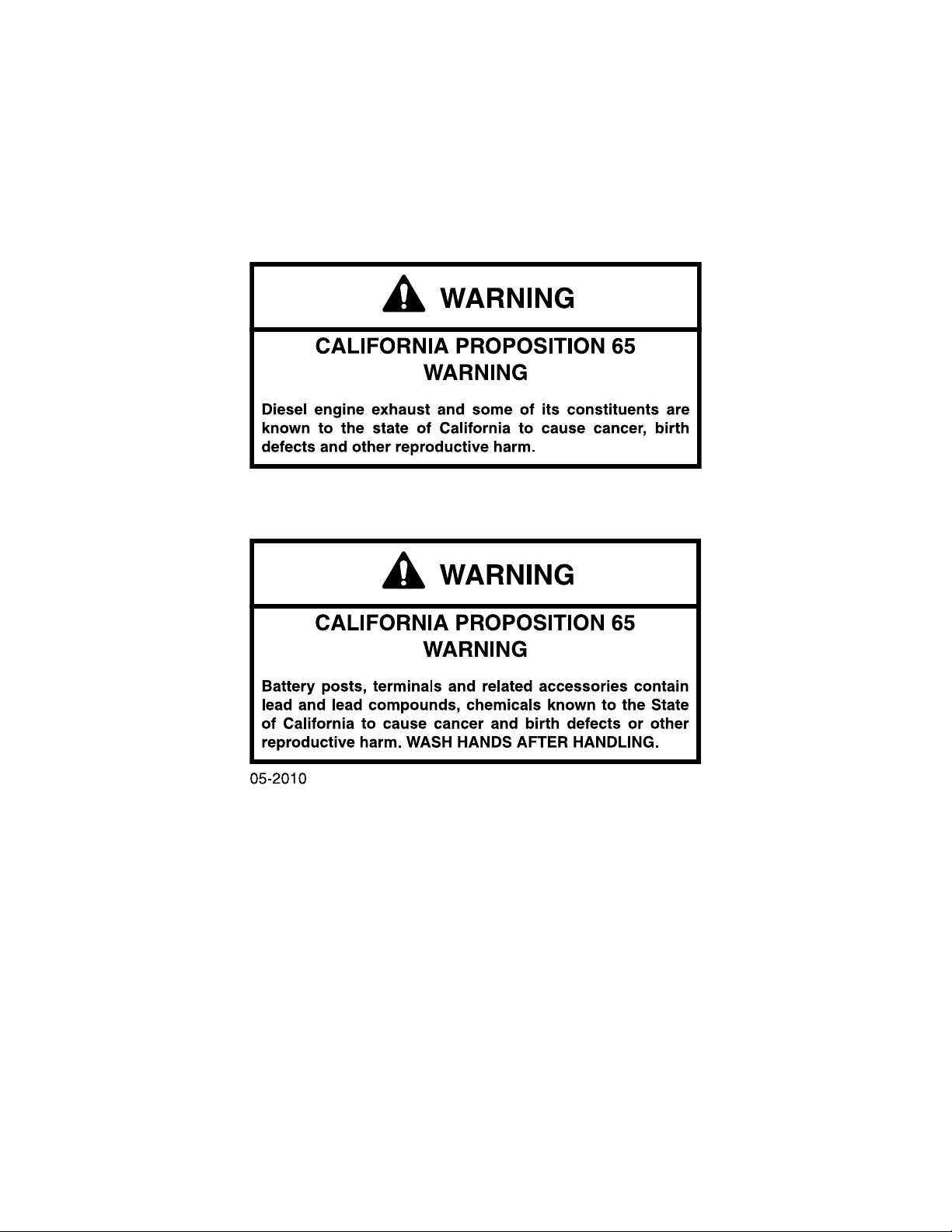
California Proposition 65
Breathing diesel engine exhaust exposes you to chemicals
known to the State of California to cause cancer and birth
defects or other reproductive harm.
• Always start and operate the engine in a wall-ventilated
area.
• If in an enclosed area, vent the exhaust to the outside.
• Do not modify or tamper with the exhaust system.
• Do not idle the engine except as necessary.
This product can expose you to chemicals including lead, which
is known to the State of California to cause cancer and birth
defects or other reproductive harm.
For more information go to www.P65Warning.ca.gov.
0-2
DX225LC-5Foreword
Page 13
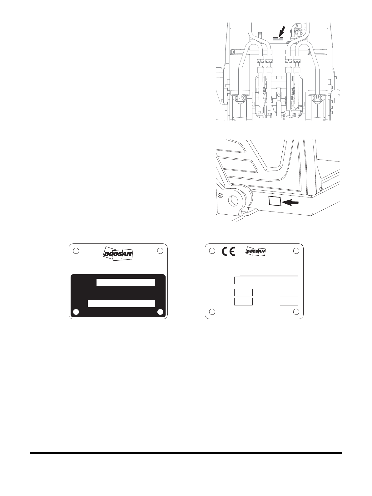
Product Identification Number (PIN)
EX1403864
Figure 1
EX1301247
Figure 2
Figure 3
EX1301248
Doosan Infracore Co., Ltd.
7-11, Hwasu-dong, Dong-gu,
Incheon, Korea
PRODUCT IDENTIFICATION NUMBER
⣆㔲#⎇ᵮ#ᴲ㛢
MADE IN KOREA
⣆㔲ᬯ
MODEL
950209-02977
Operating
Identification
Construction
Year of
Number
Product
Power
Engine
7-11, Hwasu-dong, Dong-gu,
Doosan Infracore Co., Ltd.
Incheon, Korea
kW
Mass
Model Name
Machine Type
Made in Korea
kg
First Year
of Service
950205-01325A
A PIN number is stamped on upper frame under boom foot
(
Figure 1). It is also stamped on a product identification plate
(Figure 2) on outside of cabin on right-hand side.
NOTE: Record these numbers and their locations. These will
be required whenever warranty or service work is
requested. Keep these numbers on file in case
machine is stolen.
Component Serial Numbers
There are many serial numbers on each traceable component of
the machine. Record these numbers and their locations. These
will be required whenever warranty service work is requested.
DX225LC-5
Foreword
0-3
Page 14
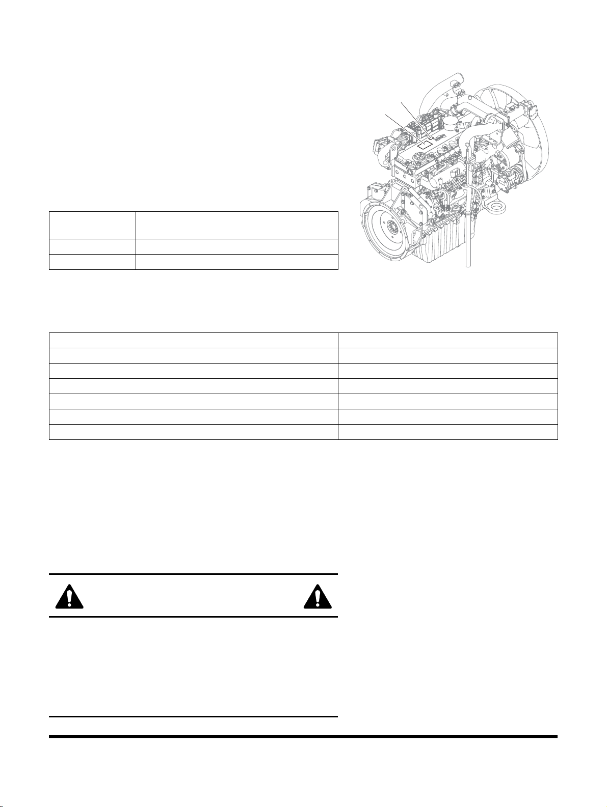
Engine Identification
1
2
EX1403746
Figure 4
Engine Data Plate
The engine data plate provides important facts about the engine.
The engine serial number (ESN) and control parts list (CPL)
provide information for service and ordering parts. The engine
data plate must not be changed unless approved by DOOSAN.
The engine data plate and engine serial number are located on
the head cover. Have the following engine data available when
communicating with a DOOSAN Authorized Repair Location.
The following information on data plate is mandatory when
sourcing service parts:
Reference
Number
1 Engine Data Plate
2 Engine Serial Number
Description
Your Machine Serial Numbers
Product Identification Number (PIN)
Machine Serial No.
Engine Serial No.
Main Pump
Swing Motor
Travel Motor
Main Control Valve
Safety Messages
Safety messages and safety decals included in this manual and
on the machine provide instructions how to operate, service and
maintain the machine. Safety messages and safety decals
indicate potential hazards and describe safety precautions
required to avoid hazards. Operator and maintenance personnel
should read and understand these safety messages and decals
before beginning operation or maintenance.
SAFETY ALERT SYMBOL
Be Prepared - Get to Know All Operating and Safety
Instructions.
This is a Safety Alert Symbol. Wherever it appears in this
manual or on safety decals on the machine, you must be
alert to the potential for personal injury or accidents.
Always observe safety precautions and follow
recommended procedures.
0-4
DX225LC-5Foreword
Page 15
Signal Words
The signal words "DANGER", "WARNING", "CAUTION" are
used throughout safety messages and safety decals in this
manual or on the machine. They indicate an existence of, and
the relative seriousness of, a hazard. All three indicate that a
safety risk is involved. Observe the precautions indicated
whenever a Safety Alert Symbol is present, no matter which
signal word appears next to it.
DANGER
DANGER - This signal word is used on safety messages and
safety labels and indicates an imminently hazardous situation
which, if not avoided, will result in death or serious injury.
WARNING
WARNING - This signal word is used on safety messages and
safety labels and indicates a potentially hazardous situation
which, if not avoided, could result in death or serious injury.
CAUTION
CAUTION - This signal word is used on safety messages
and safety labels and indicates a potentially hazardous
situation which, if not avoided, could result in minor or
moderate injury.
Other Signal Words
In addition to safety signal words, the following signal words are
used to indicate proper and effective use of machine.
IMPORTANT
This signal word identifies procedures which must be
followed to avoid damage to machine.
NOTE: The word "NOTE" identifies information for effective
use.
DX225LC-5
Foreword
0-5
Page 16

AEM SAFETY MANUAL
Figure 5
(NORTH AMERICA ONLY)
The AEM Safety Manual delivered with the machine gives
general safety information.
The AEM Safety Manual must be read and understood before
beginning operation or maintenance and is not intended to
replace the Operation & Maintenance Manual delivered with the
machine.
DX225LC-5Foreword
0-6
Page 17

FEDERAL AND CALIFORNIA EMISSION CONTROL SYSTEMS
Limited Warranty for Non-road Engines (CI) (FDICL05.8LEA (DL06P))
Owner’s Warranty Rights and Obligations
The U.S. Environmental Protection Agency (EPA), the California Air Resources Board (ARB), and DOOSAN
INFRACORE are pleased to explain the Federal and California Emission Control System Warranty on your
2015MY to 2017MY non-road engine. DOOSAN INFRACORE has designed, built and equipped the engine so as
to conform at the time of sale with all applicable regulations of the EPA and of the California ARB. In California,
new heavy-duty off-road engines must be designed, built and equipped to meet the State’s stringent anti-smog
standards.
DOOSAN INFRACORE must warrant to the initial owner, and each subsequent owner, the emission control
system on your engine for the periods of time listed below provided there has been no abuse, neglect, improper
maintenance or unapproved modifications of your engine. Your emission control system may include those parts
listed below:
1. Fuel Metering System
Fuel Supply Pump (HP Pump), Injector, Common Rail, Glow Plug
2. Air-Induction System
Intake Manifold, Turbocharger System
3. Exhaust Gas Recirculation (EGR) System
EGR Valve, EGR Cooler
4. Catalyst or Thermal Reactor System
Diesel Oxidation Catalyst (DOC), Exhaust Manifold, SCR System, Catalyst, NOx Sensor
5. Positive Crankcase Ventilation (PCV) System
Right Head Cover
6. Electronic Control System
ECU, Cam/ Crank Sensor, Coolant Temperature Sensor, MAF Sensor, MAP Sensor (Manifold Pressure
Sensor), Inlet Boost Temperature Sensor, Fuel Temperature Sensor, Common Rail Pressure Sensor
7. Miscellaneous Items Used In Above Systems
Temperature and time sensitive valve and switches
Solenoids and wiring harnesses
Hoses, clamps, fittings and tubing, sealing gasket
Pulleys, belts and idlers
Emission control information labels
Where a warrantable condition exists, DOOSAN INFRACORE CONSTRUCTION EQUIPMENT AMERICA
(hereafter "DICEA") will repair your heavy-duty off-road engine at no cost to you including diagnosis, parts, and
labor.
DX225LC-5
Foreword
0-7
Page 18

Manufacturer's Warranty Coverage
The 2015MY to 2017MY heavy-duty off-road engines are warranted for five years or 3,000 hours of operation,
whichever occurs first. If any emission-related part on your engine is defective, the part will be repaired or
replaced by DICEA.
The warranty period shall begin on the date the machine is delivered to the first retail customer.
Owner’s Warranty Responsibilities
As the heavy-duty off-road engine owner, you are responsible for the performance of the required maintenance
listed in the Operation and Maintenance Manual. DOOSAN INFRACORE and DICEA recommends that you
retain all receipts covering maintenance on your heavy-duty off-road engine, but DOOSAN INFRACORE and
DICEA cannot deny warranty solely for the lack of receipts or for your failure to ensure the performance of all
scheduled maintenance.
As the heavy-duty off-road engine owner, you should however be aware that DOOSAN INFRACORE and DICEA
may deny you warranty coverage if your heavy-duty off-road engine or a part has failed due to abuse, neglect,
improper maintenance or unapproved modifications.
Your engine is designed to operate on Ultra Low Sulfur Diesel Fuel Only. Use of any other fuel may result in
your engine no longer operating in compliance with the EPA’s emissions requirements.
You are responsible for initiating the warranty process. The EPA and California ARB suggest that you present
your heavy-duty off-road engine to a DICEA dealer as soon as a problem exists. The warranty repairs should be
completed by the dealer as expeditiously as possible.
If you have any questions regarding your warranty rights and responsibilities, you should contact your nearest
authorized DICEA dealer or contact DICEA at
Doosan Infracore Construction Equipment North America
2905 Shawnee Industrial Way
Suwanee, GA 30024
USA
1-800-743-4340
0-8
DX225LC-5Foreword
Page 19

1Safety
DX225LC-5
Safety
1-1
Page 20

SAFETY DECALS
Safety decals are attached to the machine to alert the operator
or maintenance person about potential hazards, the
consequences of potential injury, and instructions and/or actions
required to avoid the hazard. The location of the safety decals
and the description of the decals are reviewed in the following
section. Please become familiarized with all safety decals and
their messages.
Make sure that all the safety decals are in their correct location
and legible. Clean or replace the safety decals if they are
damaged, missing, or the texts and pictorials are not legible.
When you clean the safety decals, use a soft cloth, water, and
soap. Do not use solvent, gasoline, or other harsh chemicals to
clean the safety decals because this could loosen the adhesive
that secures the decals to the machine. Remember, if a safety
decal is attached to a part that is replaced, install a new safety
decal on the replacement part.
This machine uses safety decals with and without text. The type
and number of safety decals can vary depending upon
geographical regions and machine models.
Safety Decals With Text
Safety decals with text consist of a signal word, pictorial and a
text message panel. In some cases, a pictorial panel may not be
part of the safety decal.
1-2
DX225LC-5Safety
Page 21
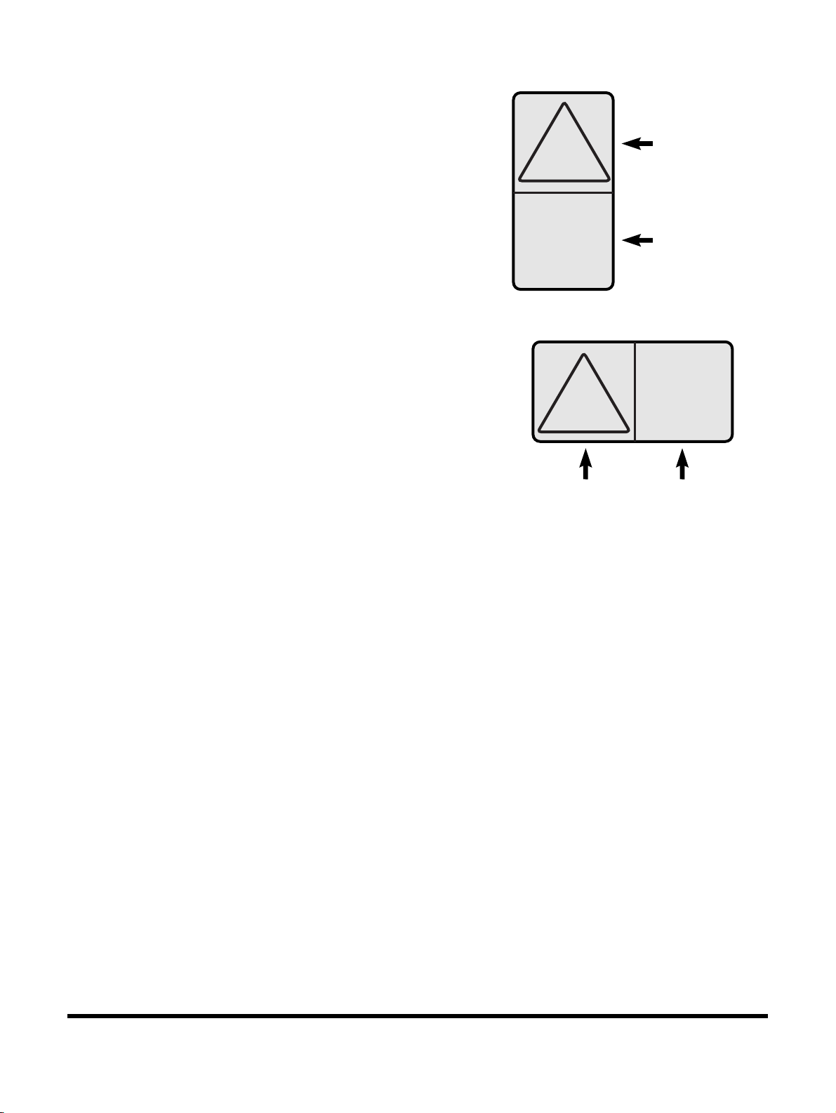
Safety Decals Without Text (No-Text)
Horizontal Configuration
Vertical Configuration
Hazard
Panel
Avoidance
Panel
Hazard
Panel
Avoidance
Panel
FG018723
Figure 1
Safety decals without text consist of a hazard panel(s) and
avoidance panel(s). Hazard panels are located at the top or left
side and the avoidance panels are located at the bottom or right
side of the decal depending on its configuration. The hazard
panels use a black triangular band and a pictorial to identify the
hazard and the potential consequences of failure to follow the
instructions. Avoidance panels use pictorials and/or prohibition
signs to identify the actions necessary to avoid the hazard.
A safety decal may contain more than one hazard panel and
more than one avoidance panel.
DX225LC-5
Safety
1-3
Page 22
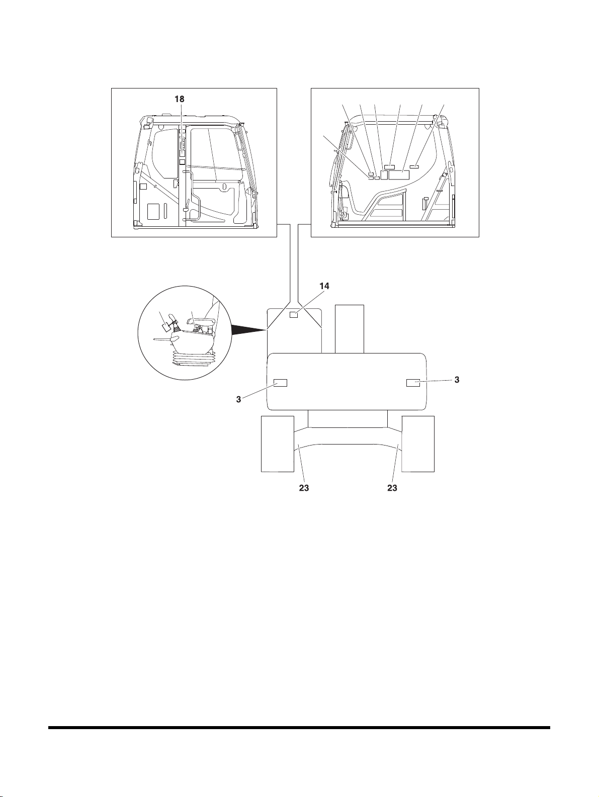
Information and Location for Safety Decals
227
DS1801352
2928 21 15 16 1
24
Figure 2
DX225LC-5Safety
1-4
Page 23
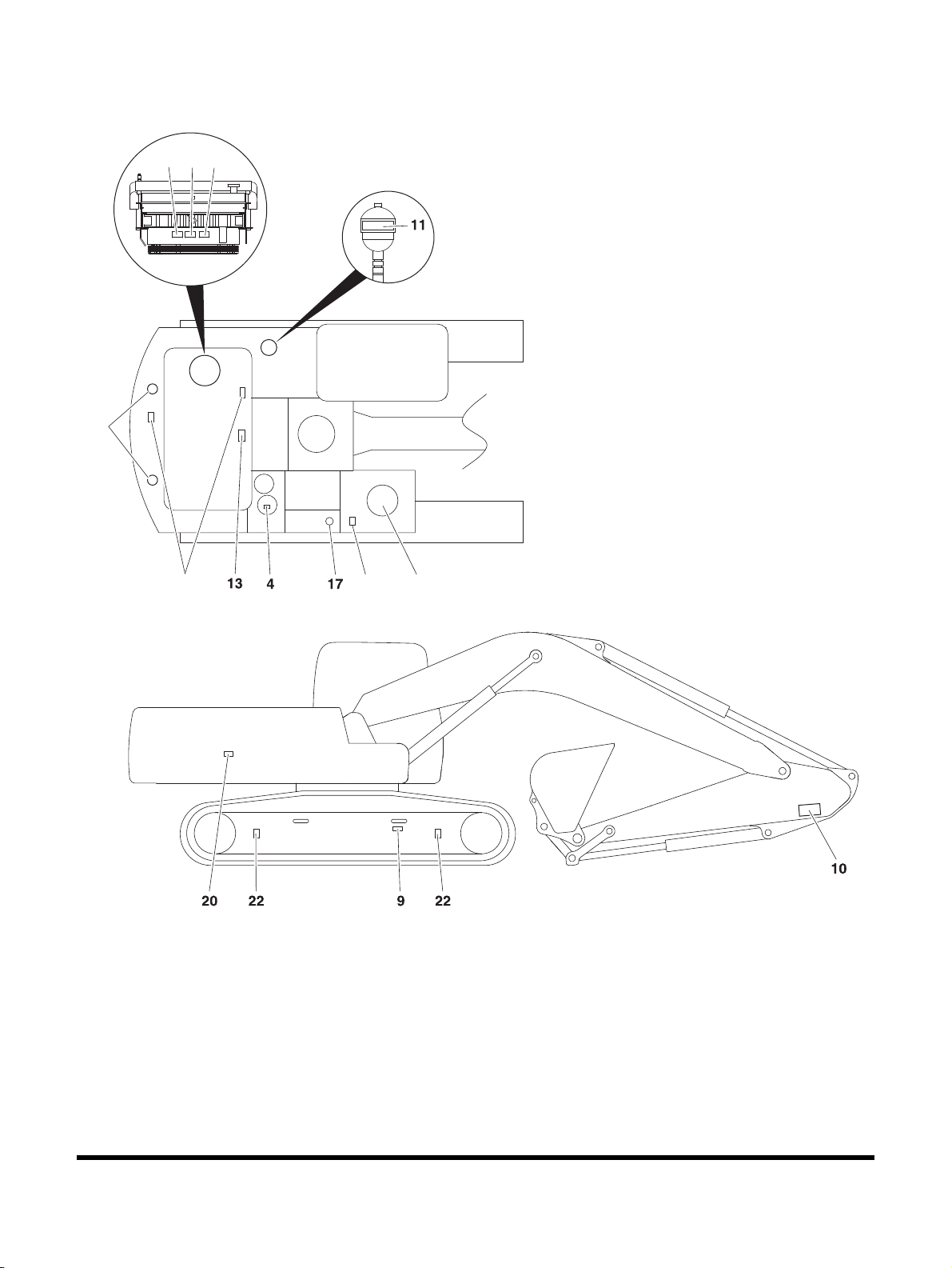
Information and Location for Safety Decals (Continued)
Figure 3
465
25
12
26
19, 7, 8
EX1403849
DX225LC-5
Safety
1-5
Page 24
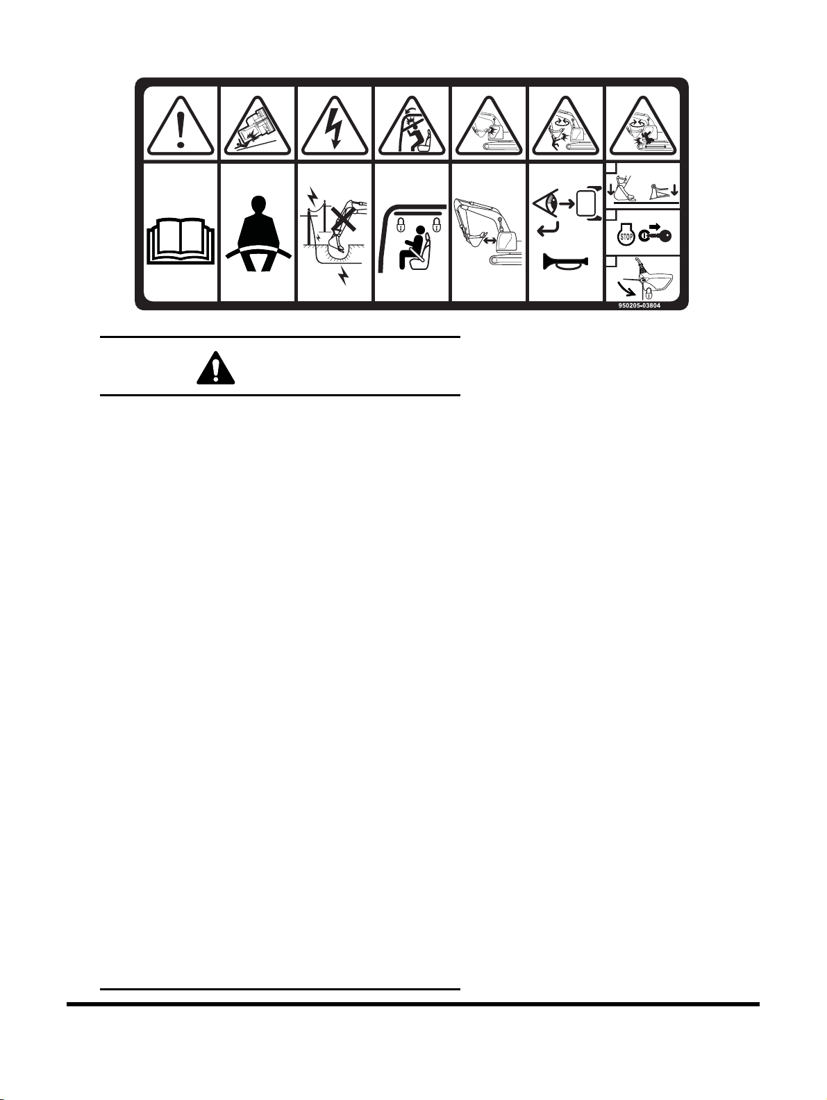
1. General Hazard (950205-03804)
EX1301176
1
2
3
WARNING
AVOID DEATH OR SERIOUS INJURY
• Never use excavator without instructions.
• Read Operation & Maintenance Manual before
operation.
• Sound the horn to alert bystanders before
operating.
• Always fasten your seat belt.
• Explosion or electrocution can occur if machine
contacts utility lines or pipes. Check for overhead
or underground lines before operating.
• Secure and lock front window when it is in raised
position.
• Attachment interference can cause death, serious
injury or machine damage. Check attachment to
machine clearance through full working cycle
before operation.
• Keep bystanders out of swing area and travel
path and always look in the travel direction.
• Ensure mirrors and rear view camera are clean
and working properly.
• Never operate machine from outside the
operator's position.
• TO LEAVE THE EXCAVATOR:
1) Lower the attachment and dozer blade (if
equipped) to the ground and make sure all
controls are in neutral.
2) Stop engine and remove key.
3) Lower safety lever to LOCK position.
1-6
DX225LC-5Safety
Page 25
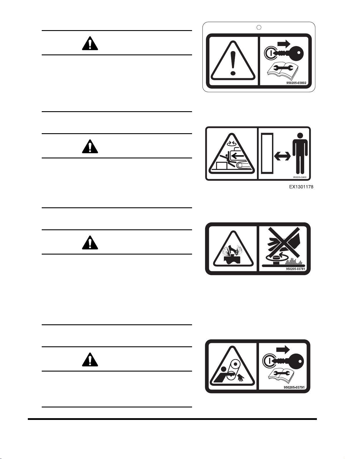
2. Warning Tag - "Do Not Operate" (950205-03802)
EX1301180
EX1301181
WARNING
AVOID DEATH OR SERIOUS INJURY
• Stop engine and remove key.
• Attach "DO NOT OPERATE" warning tag to the
controls before servicing the machine.
• Do not operate when performing inspection or
maintenance.
3. Keep Bystanders Away (950205-03803)
WARNING
AVOID DEATH OR SERIOUS INJURY
• Keep out of swing area and travel path.
• Always look in the travel direction.
EX1301177
• Make sure swing area is clear of bystanders and
objects.
4. Hot Pressurized Fluid (950205-03781)
WARNING
HOT PRESSURIZED FLUID CAN CAUSE
SERIOUS BURNS
• Do not loosen or open cap when hot.
• Before opening:
1) Turn engine off.
2) Allow machine to cool.
3) Tip cap and open slowly to relieve pressure.
5. Entanglement in Rotating Parts (950205-03791)
WARNING
ROTATING PARTS CAN CAUSE DEATH OR
SERIOUS INJURY
Keep away from belt and rotating parts. Stop engine
before servicing.
DX225LC-5
Safety
1-7
Page 26
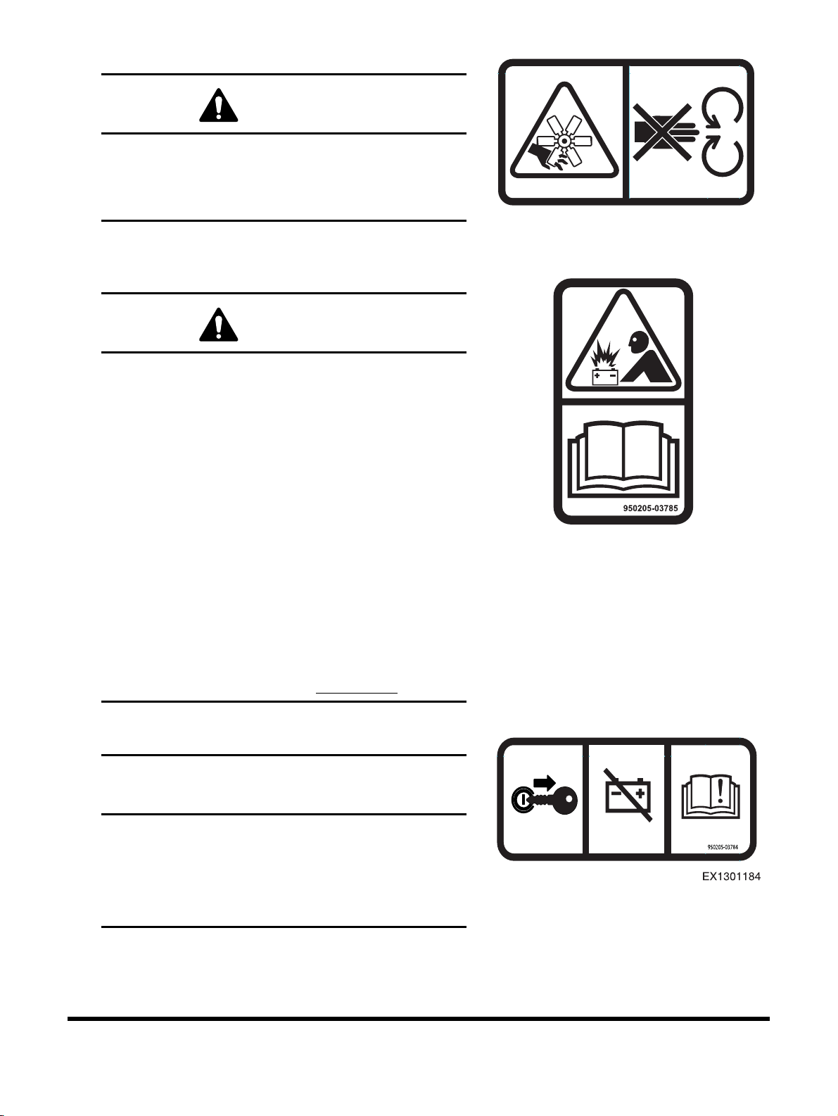
6. Rotating Fan (950205-03788)
WARNING
CONTACT WITH ROTATING FAN CAN CAUSE
DEATH OR SERIOUS INJURY
Keep away from fan and rotating parts. Stop engine
before servicing.
7. Battery Explosion (950205-03785)
WARNING
AVOID DEATH OR SERIOUS INJURY
• Read and follow instructions in Operation &
Maintenance Manual for battery maintenance.
• Keep arcs, sparks, flames, and lighted tobacco
away.
• Do not store metal tools or flammable materials
on or around batteries.
• Wear safety goggles and rubber gloves when
working with batteries.
• If battery acid contact occurs:
1) Flush your skin with water immediately and
apply baking soda or lime to neutralize the
acid.
950205-03788
EX1301182
EX1301183
2) Flush your eyes with water for 10 - 15
minutes.
3) Get medical attention immediately.
8. Battery Disconnection (950205-03784)
IMPORTANT
AVOID ELECTRICAL COMPONENT DAMAGE
Disconnecting the battery while the engine is running
can cause damage to electrical components.
Disconnect battery only when the engine is turned
OFF.
1-8
DX225LC-5Safety
Page 27
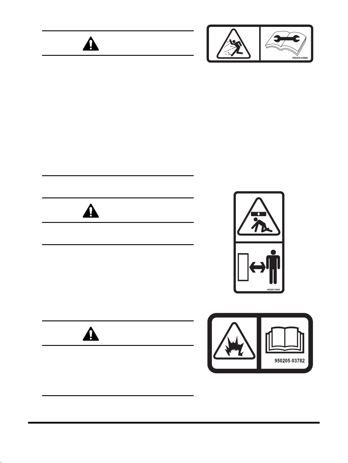
9. Flying Debris or Objects (950205-03866)
EX1301185
EX1301186
EX1301187
WARNING
HIGH-PRESSURE GREASE CAN CAUSE
DEATH OR SERIOUS INJURY
• Track adjusting systems use grease under highpressure which can penetrate body if improperly
serviced.
• NEVER LOOSEN track tension grease valve more
than one complete turn from the fully tightened
position.
• Bleed off pressure slowly and keep body away
from grease valve.
• Wear eye protection.
• Read and follow instructions in Operation &
Maintenance Manual for more information on
track adjustment.
10. Crush Hazard (950205-03805)
WARNING
AVOID DEATH OR SERIOUS INJURY
Stay clear of the boom, arm, and attachment.
11. Pressurized Gas and Fluid (950205-03782)
WARNING
AVOID DEATH OR SERIOUS INJURY
• Heat or impact can cause the accumulator to
explode.
• Keep away from flame.
• Do not weld on or drill into accumulator.
DX225LC-5
Safety
1-9
Page 28
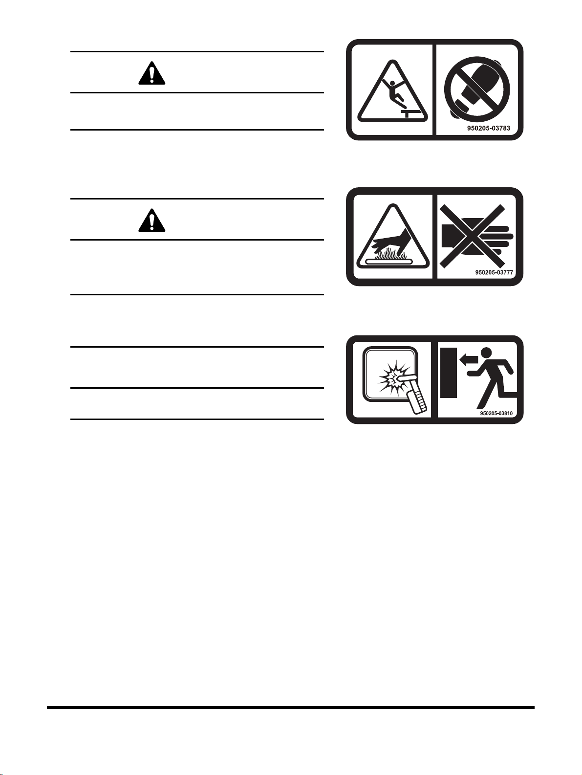
12. Fall Hazard (950205-03783)
WARNING
AVOID DEATH OR SERIOUS INJURY
Do not step in this area.
13. Hot Surface (950205-03777)
WARNING
HOT SURFACE CAN CAUSE SERIOUS BURNS
• Do not touch hot surface.
• Allow to cool before servicing.
EX1301188
EX1301189
14. Emergency Exit (950205-03810)
IMPORTANT
If primary exit is blocked, use glass breaking tool to
break glass for secondary exit.
EX1301190
1-10
DX225LC-5Safety
Page 29
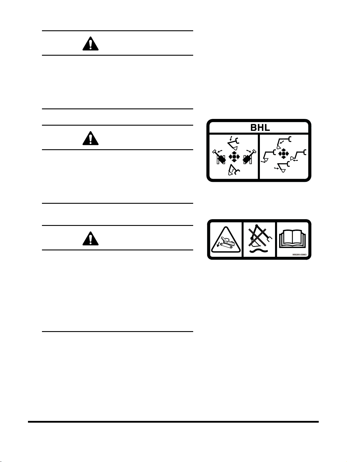
15. ISO Control Pattern (950205-03860)
WARNING
AVOID INJURY OR DEATH
Read and understand the Operation & Maintenance
Manual for more information.
Refer to "Operating Instructions" section of this
manual for details regarding the work levers
(joysticks) control functions.
BHL Control Pattern (US Only) (950205-03868)
WARNING
AVOID INJURY OR DEATH
Read and understand the Operation & Maintenance
Manual for more information.
Refer to "Operating Instructions" section of this
manual for details regarding the work levers
(joysticks) control functions.
16. Impact Hazard (Optional) (950205-03963)
WARNING
AVOID DEATH OR SERIOUS INJURY
• Activating the Intelligent Floating Boom Control
with the tracks raised up can cause the machine
to drop suddenly.
• Do not activate Intelligent Floating Boom Control
when tracks are raised.
• Do not raise tracks when control is activated.
Refer to "Intelligent Floating Boom Control (Optional)"
section of this manual for more information.
EX1301192
EX1301193
DX225LC-5
Safety
1-11
Page 30
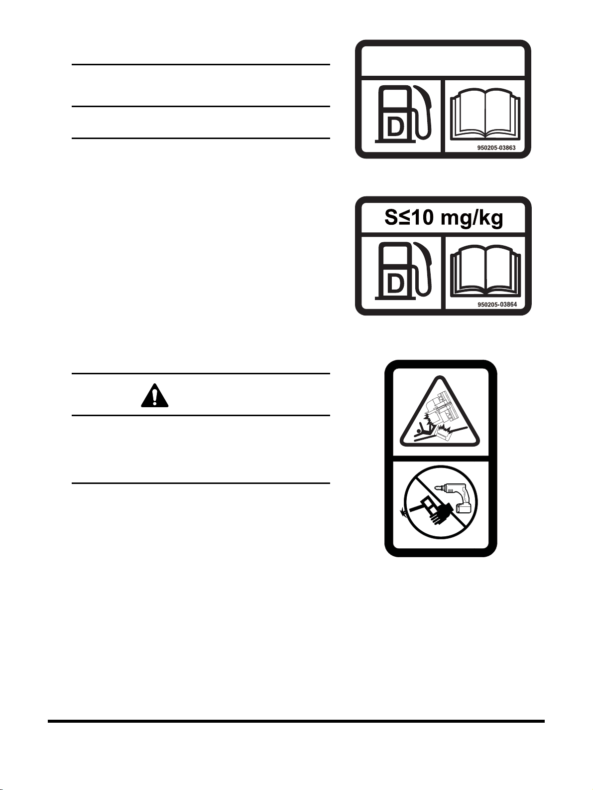
17. Ultra Low Sulfur Diesel Fuel (Optional)
950205-03861
(950205-03863, 950205-03864)
IMPORTANT
Only use Ultra Low Sulfur Diesel (ULSD) fuel with this
machine.
ULTRA LOW SULFUR
DIESEL FUEL ONLY
EX1301196
EX1301194
18. ROPS Warning (Optional) (950205-03861)
WARNING
AVOID DEATH OR SERIOUS INJURY
• Do not weld on or drill holes in the protective
structure.
• Replace ROPS, if damaged or modified.
950205-03861
EX1301197
1-12
DX225LC-5Safety
Page 31

19. Falling Object (Optional) (950205-03786)
WARNING
UNSUPPORTED DOOR CAN FALL CAUSING
DEATH OR SERIOUS INJURY
• To open door:
1) Hold door firmly.
2) Lift door slowly until locking device
engages.
• To close door:
1) Hold door firmly.
2) Press locking device to disengage.
3) Lower door slowly.
EX1301198
DX225LC-5
Safety
1-13
Page 32

20. Hydraulic Oil Check (Optional) (950205-06281, 950205-03965, 950205-06282)
IMPORTANT
INCORRECT OIL LEVEL OR INCORRECT FLUID CAN
CAUSE HYDRAULIC SYSTEM DAMAGE
Place the excavator with the boom and arm fully
extended with the attachment on the ground before
checking hydraulic fluid level.
Use hydraulic oil which is suitable for machine.
32
950205-06281
EX1505097
1-14
EX1505098
68
950205-06282
EX1505099
DX225LC-5Safety
Page 33

21. Hydraulic Breaker (Optional) (950205-03964)
EX1402396
950212-02440
IMPORTANT
AVOID HYDRAULIC SYSTEM DAMAGE
To adjust breaker impact, see Operation &
Maintenance Manual for additional instructions.
22. Lift/Tie down (Optional) (950205-03815)
Identifies lift point and tie down point location.
EX1301200
23. Tie down (Optional) (950205-03816)
Identifies tie down point location.
24. Electric Welding Attention (950212-02440)
IMPORTANT
950205-03815
EX1301201
EX1301203
Electrical welding on the frame can damage the
engine's electronic control unit (ECU).
DX225LC-5
Safety
1-15
Page 34

25. Do Not Lift (950205-03570)
EX1402619
WL1300370
ISO 22241 DIN 70070
950205-01489A
WARNING
AVOID DEATH OR SERIOUS INJURY
Not a lift point for machine.
Refer to the "Lifting Machine" section of this manual
for detailed information regarding the lifting point.
26. DEF (AdBlue) (950205-01489A)
IMPORTANT
• Use only the specified diesel exhaust fluid.
• See the Operation & Maintenance Manual for
more information.
1-16
DX225LC-5Safety
Page 35

27. Dozer (950205-03881)
WE1500865
950205-05450
WARNING
AVOID DEATH OR SERIOUS INJURY
• Check the dozer blade location before traveling.
When the blade is to the rear, operate the steering
levers/foot pedal in the opposite direction to
when the blade is in the front.
• Before moving, make sure there are no persons
or property in the way. Never allow riders.
Sound the horn to alert workers and bystanders
that you are about to move the machine.
• Always make sure the path is clear during travel.
• Use extreme caution when reversing travel.
Be sure there is a clear path behind the machine.
• Operate the travel control levers smoothly to
avoid sudden starts or stops.
• Before leaving the operator's seat, make sure to
lock out all control systems and stop engine to
avoid accidental activation of the controls.
950205-03881
EX1402247
28. Lifting Capacity (950205-05450)
WARNING
AVOID DEATH OR SERIOUS INJURY
Whenever you handling and lifting objects, ensure
operator manual available on the station and refer
lifting chart.
29. California Proposition 65 (950205-07650)
WARNING: Breathing diesel engine exhaust exposes
you to chemicals known to the State of California to cause
cancer and birth defects or other reproductive harm.
• Always start and operate the engine in a wall-ventilated area.
• If in an enclosed area, vent the exhaust to the outside.
• Do not modify or tamper with the exhaust system.
• Do not idle the engine except as necessary.
For more information go to www.P65warning.ca.gov.
WARNING: This product can expose
you to chemicals including lead,
which is known to the state of
California to cause cancer and birth
defects or other reproductive harm
For more information go to
www.P65warning.ca.gov/diesel
950205-07650
DS1801347
DX225LC-5
Safety
1-17
Page 36

GENERAL
Safe Operation is Operator's
Responsibility
Only trained and authorized personnel should operate and
maintain the machine.
Follow all safety rules, regulations and instructions when
operating or performing maintenance on machine.
• Do not operate machine if you are under the influence of
drugs or alcohol. An operator who is taking prescription
drugs must get medical advice to determine if he or she
can safely operate a machine.
• When working with other personnel on a work site, be sure
that all personnel know nature of work and understand all
hand signals that are to be used.
• Be sure that all guards and shields are installed in their
proper location. Have guards and shields repaired or
replaced immediately if damaged.
• Be sure that you understand the use and maintenance of
all safety features such as safety lever and seat belt. Use
them properly.
• Never remove, modify or disable any safety features.
Always keep them in good operating condition.
• Always check for and know the location of underground
and overhead utility lines before excavating.
• Failure to use and maintain safety features according to
instructions in this manual, Safety Manual and Shop
Manual can result in death or serious injury.
Know Your Machine
Know how to operate your machine. Know the purpose of all
controls, gauges, signals, indicators and monitor displays. Know
the rated load capacity, speed range, braking and steering
characteristics, turning radius and operating clearances. Keep in
mind that rain, snow, ice, loose gravel, soft ground, slopes etc.,
can change operating capabilities of your machine.
1-18
DX225LC-5Safety
Page 37

Proper Work Tools and Attachments
FG018457
Figure 4
Only use work tools and attachments that are recommended by
DOOSAN for use on DOOSAN machines. When installing and
using optional attachments, read instruction manual for
attachment, and general information related to attachments in this
manual. Because DOOSAN cannot anticipate, identify or test all
attachments that owners may want to install on their machines,
contact DOOSAN for written authorization and approval of
attachments, and their compatibility with optional kits.
Attachments and attachment control systems that are
compatible with the machine are required for safe and reliable
machine operation. Do not exceed maximum operating weight
(machine weight plus attachment) that is listed on ROPS
certification plate.
Make sure that all guards and shields are in place on machine
and on work tool. Depending on type or combination of work
equipment, there is a potential that work equipment could
interfere with the cabin or other parts of machine. Before using
unfamiliar work equipment, check if there is any potential of
interference, and operate with caution.
While you are performing any maintenance, testing, or
adjustments to attachments, stay clear of the following areas:
cutting edges, pinch points, and crushing surfaces.
Never use attachment as a work platform or manlift.
Contact your DOOSAN distributor about auxiliary hydraulic kits
for attachments installation. If you are in doubt about
compatibility of a particular attachment with a machine, consult
your DOOSAN distributor.
Pressurized Fluids
Pressurized air or fluids can cause debris and/or fluids to be
blown out. This could result in death or serious injury.
Immediately after operations are stopped, coolant, engine oil,
and hydraulic oil are at their highest temperatures and the
radiator and hydraulic tank are still under pressure. Always wait
for temperature to cool down. Follow specified procedures when
attempting to remove caps, drain oil or coolant, or replacing
filters. Always wait for temperature to cool down, and follow
specified procedures when performing these operations. Failure
to do so can result in death or serious injury.
When pressurized air and/or pressurized water is used for
cleaning, wear protective clothing, protective shoes, and eye
protection. Eye protection includes goggles or a protective face
shield.
Pressure can be trapped in a hydraulic system and must be
relieved before maintenance is started.
Releasing trapped pressure can cause sudden machine
movement or attachment movement. Use caution if you
disconnect hydraulic lines or fittings.
DX225LC-5
Safety
1-19
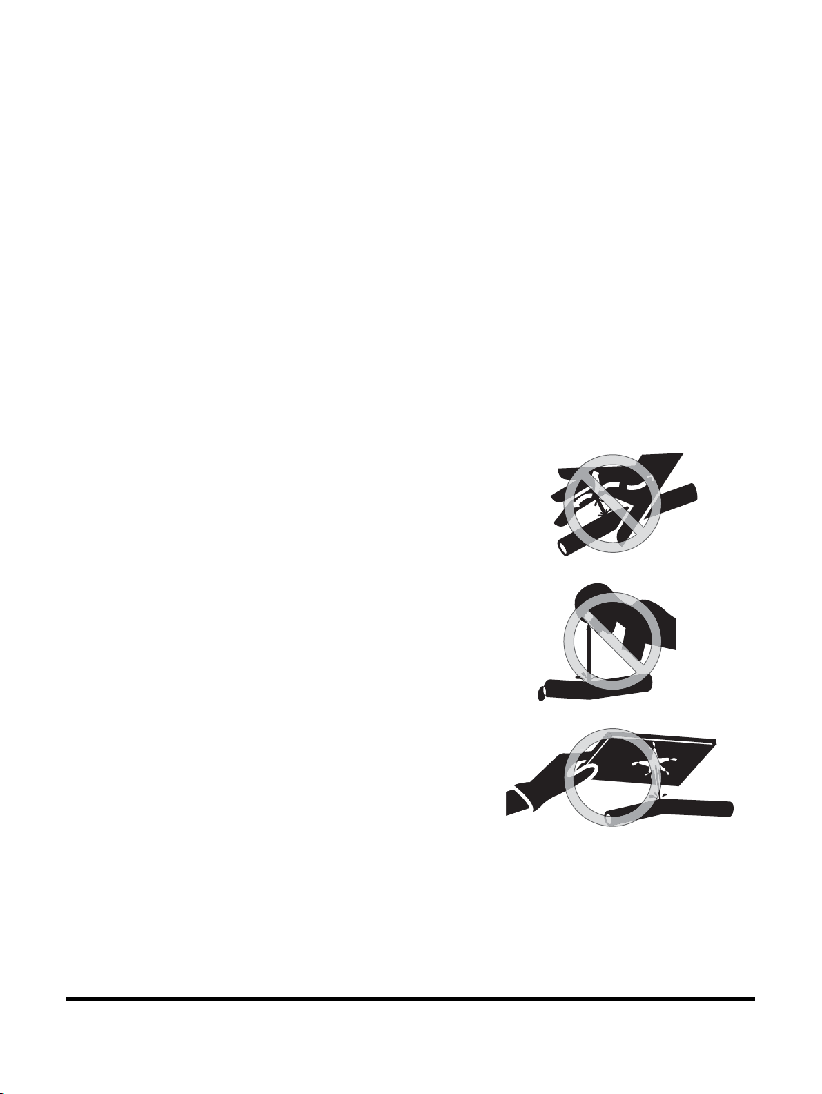
Page 38

High-pressure oil that is released can cause a hose to whip or oil
HAOA110L
Figure 5
HAOA100L
Figure 6
to spray. Fluid penetration can result in death or serious injury. If
fluid enters skin or eyes, get immediate medical attention from a
physician familiar with this injury.
Obey all local laws and regulations for disposal of liquids.
To prevent hot coolant from spraying out, stop engine and wait
for coolant to cool. Using gloves, slowly loosen cap to relieve
pressure.
Flying or Falling Objects
On work sites where there is a potential hazard that flying or
falling objects can hit operator's cabin, select and use a guard to
match operating conditions for additional operator protection.
Working in mines, tunnels, deep pits, and loose or wet surfaces,
could produce hazard of falling rocks or flying objects. Additional
protection for operator's cabin could be required such as an
Operator Protection Guard (OPG) or window guards. Contact
your DOOSAN distributor for information on available protective
guards.
To prevent personnel from being struck by flying objects, keep
personnel out of work area.
1-20
DX225LC-5Safety
Page 39

Personal Protective Equipment (PPE)
HAOA020L
Figure 7
Do not wear loose clothing and accessories. Secure long hair.
These items can snag on controls or on other parts of
equipment.
Do not wear oily clothes. They are highly flammable.
Do not forget that some risks to your health may not be
immediately apparent. Exhaust gases and noise pollution may
not be visible, but these hazards can cause disabling or
permanent injuries. Breathing masks and/or ear protection may
be required.
Wear a hard hat, safety shoes, safety goggles, mask, leather
gloves, earplugs and other protective equipment, as required.
While working on machine, never use inadequate tools. They
could break or slip, or they may not adequately perform intended
functions.
Correction of Machine Problems
If any machine problems are found during operation and
maintenance (noise, vibration, smell, incorrect gauges, smoke,
oil leakage, etc.), or if any abnormal warning alerts are displayed
on display monitor, stop the machine and take the necessary
corrective actions. Do not operate machine until problem has
been corrected.
Crushing and Cutting
Keep objects away from moving fan blades. Fan blades can
throw and cut objects.
Do not use a wire rope that is kinked or frayed, or a wire rope
with any loss of diameter. Wear leather gloves when handling a
wire rope.
When striking a loose retainer pin, it can fly out and can cause a
serious injury. Make sure that area is clear of personnel when
striking a retainer pin. To avoid injury to your eyes, wear safety
goggles when striking a retainer pin.
Do not put your hand, arm or any other part of your body
between movable parts. If going between movable parts is
necessary, always position and secure work equipment so it
cannot move. Properly support equipment before performing
any work or maintenance under raised equipment.
If control levers are operated, clearance between machine and
work equipment will change and this may lead to serious
damage or can result in death or serious injury. Stay clear of
areas that may have a sudden change in clearance with
machine movement or equipment movement. Stay clear of all
rotating and moving parts. Unless instructed, never attempt
adjustments while machine is moving or while engine is running.
DX225LC-5
Safety
1-21
Page 40

Do not depend on hydraulic cylinders to support raised
HDO1010L
Figure 8
FG019095
Figure 9
FG019096
Figure 10
equipment. Equipment can fall if a control is moved, or if a
hydraulic line breaks, is loosened or disconnected.
If it is necessary to remove guards to perform maintenance,
always install guards after maintenance is completed.
Hot Coolant and Oils - Burn Prevention
Do not touch any part of an operating engine. Immediately after
operations are stopped, coolant, engine oil, and hydraulic oil are
at their highest temperatures. The radiator and hydraulic tank
are still under pressure. Always wait for temperature to cool
down. Attempting to remove caps, drain oil or coolant, or
replacing filters may lead to serious burns, if done when hot.
Relieve all pressure in air system, hydraulic oil system,
lubrication system, fuel system, and cooling system, before any
lines, fittings or related items are disconnected.
To prevent hot oil or coolant from spraying out, stop engine, wait
for oil and coolant to cool. Using gloves, slowly loosen cap to
relieve pressure.
1-22
DX225LC-5Safety
Page 41

Fire and Explosion Prevention
Figure 11
Figure 12
FG018458
All fuels, most lubricants and some coolant mixtures are
flammable and can cause a fire resulting in death or serious
injury, and property damage. Flammable fluids that are leaking
or spilled onto hot surfaces or onto electrical components can
cause fire.
Inspect for and remove all flammable materials such as spilled
fuel and oil, and debris from machine. Do not allow any
flammable materials to accumulate on machine.
Always observe the following:
• Add fuel, oil, antifreeze and hydraulic fluid to machine only
in a well ventilated area. Machine must be parked with
controls, lights and switches turned "OFF". Engine must be
"OFF" and any flames, glowing embers, auxiliary heating
units or spark causing equipment must be extinguished, or
turned "OFF" and kept well clear of machine.
• Dust that is generated from repairing or grinding
nonmetallic hoods or nonmetallic fenders can be toxic,
flammable and explosive. Repair these components in a
well ventilated area away from flames or sparks and wear
dust mask when grinding painted parts.
HDO1015I
Maintenance
The machine and some attachments have components that are
at high temperatures under normal operating conditions. The
primary source of high temperatures are the engine and exhaust
system. If damaged or incorrectly maintained, the electrical
system can be a source of arcs or sparks.
Flammable debris (leaves, straw, etc.) must be removed
regularly. If flammable debris is allowed to accumulate, it can
cause a fire hazard. Clean machine often to avoid this
accumulation. Flammable debris in an engine compartment is a
potential fire hazard.
The operator's area, engine compartment and engine cooling
system must be inspected every day and cleaned. This is
necessary to prevent fire hazards and overheating.
Operation
Do not use machine where exhaust, arcs, sparks or hot
components can contact flammable material, explosive dust or
gases.
Do not operate machine near any flame.
Exhaust shields (if equipped) protect hot exhaust components
from oil spray or fuel spray in case of a break in a line, hose, or
seal. Exhaust shields must be correctly installed.
DX225LC-5
Safety
1-23
Page 42
Electrical
EX1400129
Figure 13
Check all electrical wiring and connections for damage daily.
Keep battery terminals clean and tight. Repair or replace any
damaged part or wires that are loose or frayed. Clean all
electrical connections and tighten all electrical connections.
Never check battery charge by placing a metal object across
terminal posts. Use a voltmeter or a hydrometer.
Battery gas can explode and can result in death or serious
injury. Follow procedures in this manual for connecting battery
and for jump-starting. Do not jump-start or charge a frozen or
damaged battery. Keep any flames or sparks away from
batteries. Do not smoke in battery charging area.
Improper jumper cable connections can cause an explosion that
can result in death or serious injury. Refer to
"Starting Engine
with a Booster Cable" on page 3-12, for proper procedure in this
manual.
Do not charge a frozen battery. This can cause an explosion.
After market radios or other electric operated equipment in cabin
must have a fuse in the electrical circuit.
Hydraulic System
Check hydraulic tubes, hoses and fittings for damage, wear or
for leaks. Hydraulic lines and hoses must be properly routed and
have adequate support and secure clamps. Leaks can cause
fires. Never use a flame or bare skin to check for leaks.
Tighten or replace any parts that show leakage.
Check that all hose and tube clamps, guards, and cushions are
securely attached. If they are loose, they can vibrate during
operation and rub against other parts. This can cause damage
to hoses and cause high-pressure oil to spray on hot surfaces,
causing a fire and death or serious injury.
Always clean fluid spills. Do not use gasoline or diesel fuel for
cleaning parts. Use commercial nonflammable solvents.
DX225LC-5Safety
1-24
Page 43

Fueling
EX1400130
Figure 14
Figure 15
FG018458
Use caution when you are refueling a machine.
Fuel is flammable and can catch fire if it is brought close to a
flame.
Stop engine and let it cool before adding fuel. Do not smoke
while you are refueling a machine. Do not refuel a machine near
flames or sparks. Fill fuel tank outdoors.
Keep fuel and other fluid reservoir caps tight and do not start
engine until caps have been secured.
Store fuels and lubricants in properly marked containers away
from unauthorized personnel. Store oily rags and any flammable
materials in protective containers.
Static electricity can produce dangerous sparks at fuel filling
nozzle. In very cold, dry weather or other conditions that could
produce a static discharge, keep tip of fuel nozzle in constant
contact with neck of fuel filling nozzle, to provide a ground.
Always place plastic fuel containers on the ground before filling.
Never Use Ether Starting Aids
Do not use ether or starting fluids on any engine that has glow
plugs, or an electric grid type manifold heater. These starting
aids can cause an explosion and result in death or serious
injury.
Use procedures in this manual for connecting battery and for
jump-starting.
Welding and Grinding
Always clean machine and attachment, set battery disconnect
switch to "OFF" position, and disconnect wiring from electronic
controllers before welding. Cover rubber hoses, battery and all
other flammable parts. Keep a fire extinguisher near machine
when welding.
Toxic dust or gas can be produced when grinding or welding
painted parts. Grinding or welding painted parts must be done in
a well ventilated area. Wear dust mask when grinding painted
parts.
Dust generated from repairing nonmetallic parts such as hoods,
fenders or covers can be flammable or explosive.
Repair such components in a well ventilated area away from
flames or sparks.
Do not weld on lines or on tanks that contain flammable fluids.
Do not flame cut lines or tanks that contain flammable fluid.
Clean any such lines or tanks thoroughly with a nonflammable
solvent before welding or flame cutting.
DX225LC-5
Safety
1-25
Page 44

If a Fire Occurs
FG018459
Figure 16
HDO1009L
Figure 17
Figure 18
If a fire occurs:
• Do not attempt to move machine or continue operations.
• Turn starter switch to "O" (OFF) position to stop engine.
• Use handrails, guardrails and steps to get off machine.
• Immediately call for help or fire station.
• When using a fire extinguisher, always aim extinguisher at
base of fire.
• If an optional fire extinguishing system is in place, be
familiar with its operating procedures.
NOTE: Depending on job conditions, other procedures could
be necessary if a fire occurs.
Fire Extinguisher and First-aid Kit
(Emergency Medical Kit)
To be prepared in the event of a fire:
• Be sure that fire extinguishers have been provided and
read labels to ensure that you know how to use them. It is
recommended that an appropriately sized (2.27
larger) multipurpose A/B/C fire extinguisher be mounted in
cabin. Check and service fire extinguisher at regular
intervals and make sure that all work site crew members
are adequately trained in its use.
kg [5 lb] or
• Inspect fire extinguisher and service fire extinguisher
regularly.
• Follow instructions on extinguisher instruction plate.
• Keep a first aid kit in storage compartment (Figure 18) and
keep another kit at work site. Check kit periodically and
keep it properly supplied.
• Keep emergency numbers for doctor, ambulance service,
hospital and fire department readily available.
EX1403736
1-26
DX225LC-5Safety
Page 45

Electrical System and Electrical Shock
Never short across starter terminals or across batteries.
Shorting could damage electrical system and engine neutral
start system.
When engine is running or immediately after it has stopped, high
voltage is generated at injector terminal and inside engine
controller, so there is a potential for an electrical shock. Never
touch injector terminal or inside of engine controller.
NOTE: If it is necessary to touch injector terminal or inside
engine controller, contact your DOOSAN distributor.
Roll-over Protective Structure (ROPS)
The operator's cabin is a ROPS certified structure for protecting
the seat-belted operator. It absorbs the impact energy of a rollover impact. Do not allow machine weight (mass) to exceed
certified value on certification plate. If weight is exceeded, the
ROPS structure will not be able to fulfill its safety function.
Do not increase machine weight beyond certified value by
modifying machine or by installing attachments on machine. If
weight limit of protective equipment is exceeded, protective
equipment will not be able to protect operator, and this can
result in death or serious injury. Always observe the following:
• This machine is equipped with a protective structure. Do
not remove protective structure and perform operations
without it.
• Never modify the operator's cabin by welding, grinding,
drilling holes or adding attachments unless instructed by
DOOSAN in writing. Changes to the cabin can cause loss
of operator protection from roll-over and falling objects, and
result in death or serious injury.
• When protective structure is damaged or deformed by
falling objects or by rolling over, its strength will be reduced
and it will not be able to adequately protect the operator.
Contact your DOOSAN distributor if you have any
questions about the ROPS. Never repair a damaged
ROPS cabin.
• Always wear your seat belt when operating machine.
DX225LC-5
Safety
1-27
Page 46

ROPS Certification
Figure 19
This DOOSAN excavator has an operator's cabin that meets
ROPS requirements. The seat belt must be worn for roll-over
protection.
The ROPS certification plate (Figure 19) is found on the left side
of the cabin on most models. It may vary slightly in its location
on some models.
Check the ROPS cabin, mounting, and hardware for damage.
Never modify the ROPS cabin. Replace the cabin and hardware
if damaged. See your DOOSAN distributor for parts.
ROPS − Roll-over Protective Structure complies with
12117-2:2008, EN13531:2001.
ISO
WARNING
AVOID DEATH OR SERIOUS INJURY
Never modify the operator cabin by welding, grinding,
drilling holes or adding attachments unless instructed in
writing by DOOSAN. Changes to the cabin can cause loss
of operator protection from roll-over and falling objects,
and can result in death or serious injury.
EX1300529
DX225LC-5Safety
1-28
Page 47

Protecting Cabin from Flying or Falling Objects (Optional)
1
FG020947
Figure 20
2
FG018595
Figure 21
In a work site where additional operator protection is necessary
from falling or flying objects, install adequate protective guards
on the cabin.
For breaker operation, install a front guard (1, Figure 20) and
apply a laminated coating sheet to front glass. Contact your
DOOSAN distributor for recommendations.
When performing demolition or cutting operation, install a front
guard and top guard.
Apply a protective laminated coating sheet to outside of front
window. This will prevent glass from being scratched by dust
when cleaning it or running wipers.
When working in mines, quarries or other work sites where there
is a hazard of falling rocks, install Operator Protection Guard
(OPG) (2,
Figure 21) and apply a laminated coating sheet to
front glass.
When OPG is installed, and front window needs to be cleaned,
loosen bolts marked with arrows (
Figure 21). Be sure to tighten
bolts when done.
Never attempt to alter or modify any protective structure
reinforcement system, by drilling holes, welding, remounting or
relocating fasteners. Any serious impact or damage to system
requires a complete inspection of the structure. Reinstallation,
recertification and/or replacement of system may be necessary.
Contact your DOOSAN distributor for available safety guards
and/or recommendations to protect against objects that could
strike operator's cabin. Make sure that all other work site crew
members are kept away from excavator when operating.
If any glass on machine is broken, replace it with new glass
immediately.
NOTE: The preceding instructions assume that conditions
are for standard operations, but it may be necessary
to add additional guards depending on operating
conditions or local rules or regulations for the work
site. Always contact your DOOSAN distributor for
advice.
DX225LC-5
Safety
1-29
Page 48

Emergency Exit from Operator's Station
Figure 22
This machine is equipped with a glass breaking tool. It is found
on left pillar of cabin. This tool can be used to break the glass to
exit from cabin in an emergency. Grip handle firmly and use
sharp point to break glass.
• Be careful also not to slip on broken pieces of glass on
ground.
WARNING
AVOID DEATH OR SERIOUS INJURY
Protect your eyes when breaking the glass.
EX1300679
DX225LC-5Safety
1-30
Page 49

TRANSPORTATION
Obey State and Local Over-the-Road
Regulations
Check federal, state and local laws and regulations regarding
weight, width and length of a load before making preparations
for transporting on public roads or highways.
The hauling vehicle, trailer and load must be in compliance with
applicable regulations for the shipping route.
Partial disassembly of excavator may be necessary to meet
travel restrictions or particular conditions at work site. See Shop
Manual for information on partial disassembly.
Refer to "Transportation" on page 5-1, for information on
loading, unloading and towing.
The machine can be disassembled into parts for transporting.
Contact your DOOSAN distributor for assistance with
disassembly.
Loading and Unloading
To prevent machine tipping or roll-over when loading or
unloading machine, always do the following:
• Perform loading and unloading only on firm and level
ground. Maintain a safe distance from edge of road or
drop-off.
• Never use work equipment to load or unload machine. The
machine may fall or tip over.
• Always use loading ramps of adequate strength and
capacity. Be sure that ramps are wide, and long enough to
provide a safe loading slope. Take steps to prevent ramps
from moving out of position or coming off.
• Clean ramp surfaces so they are free of grease, oil, ice and
loose materials. Remove dirt from machine tracks and
undercarriage. On a rainy day, be careful since ramp
surfaces can be slippery.
• Turn auto idle switch "OFF".
• Run engine at low speed and travel slowly.
• When on ramps, do not operate any control lever except
for travel lever.
• Never correct your steering on ramps. If necessary, drive
off ramps, correct machine direction, then drive back onto
ramps.
• When driving up or down ramps, the center of gravity of
machine will change suddenly causing the tracks to drop
down to the ramps or trailer. This will occur at the joint
between the ramps and trailer. Travel slowly over this point.
DX225LC-5
Safety
1-31
Page 50

• For machines equipped with a cabin, always lock door
after loading machine to prevent door from suddenly
opening during transportation.
Transporting Machine
When transporting machine on a trailer or truck, do the following:
• The weight, transportation height, and overall length of
machine may change depending on work equipment
attached to it. Always check the machine dimensions and
work equipment's dimensions before transporting.
• When passing over bridges or structures on private land,
check that structure is strong enough to support weight of
machine. Before traveling on public roads, check with
appropriate authorities and follow their instructions.
1-32
DX225LC-5Safety
Page 51

OPERATION
Always make sure that the machine is properly maintained.
Before Engine Starting
Machine Condition
Every day before starting engine for first time, perform the
following checks and repair machine before operating, as
necessary. If these checks are not properly done death or
serious injury could result.
• Check coolant, fuel, and hydraulic tank oil levels, and
check for clogged air cleaner and damage to electrical
wiring.
• Check operation of gauges, cameras (if equipped) and
angle of mirrors, and check that safety lever is in LOCKED
position.
• Check that work equipment and travel controls move
freely, and work controls return to "NEUTRAL" when
released.
• Check that attachment is properly attached and locked.
Make sure that the machine is equipped with a lighting system
that is adequate for job conditions and lights are working
properly.
Before moving machine, check position of undercarriage. The
normal travel position is with idler wheels to front under cabin
and drive sprockets to rear. When undercarriage is rotated in
reversed position, directional or travel controls must be operated
in opposite directions.
Before performing checks, move machine to an area where
there are no obstructions, and operate slowly. Do not allow
personnel near machine.
Know maximum operating dimensions of your machine.
DX225LC-5
Safety
1-33
Page 52

Work Site
EX1300680
DANGER
No Entry
Figure 23
Before starting operations, thoroughly check work area for any
hazards, such as underground utility lines, overhead electrical
lines, unstable ground, excessive slopes, etc.
Before starting engine and moving machine, make sure that no
one is underneath machine, around machine, or on machine.
Know width and length of your machine and work equipment to
maintain proper clearance when you operate machine or work
equipment near fences or near boundary obstacles.
Know appropriate work site hand signals and personnel that are
authorized to give hand signals. Follow hand signals from only
one person.
If you need to operate on a street, protect pedestrians and cars
by designating a person for work site traffic duty or by erecting
fences and posting "No Entry" signs around work site.
Erect barricades or fences, post "No Entry" signs, and take other
steps to prevent people from coming close to or entering work
site. If people come too close to a moving machine, they may be
struck or caught by machine, and this can result in death or
serious injury.
1-34
DX225LC-5Safety
Page 53

Mounting/Dismounting
Figure 24
EX1301112
Figure 25
Figure 26
Before getting on or off machine, if there is any oil, grease, or
mud on handrails, guardrails, steps, or track shoes, wipe it off
immediately. Always keep these parts clean. Repair any
damage and tighten any loose bolts.
Never jump on or off machine. In particular, never get on or off a
moving machine. These actions can result in death or serious
injury.
When getting on or off machine, always face machine. Maintain
three-point contact (both feet and one hand or one foot and both
hands) with handrails, guardrails, steps, and track shoes to
ensure that you support yourself securely.
Never hold onto any control levers when getting on or off
machine.
Securely latch door. If you grip handrail inside door when
moving on top of track shoes, and door latch is not securely
engaged, door may move and cause you to fall.
Use points marked by arrows in diagram when getting on or off
machine.
Do not carry tools or supplies when you mount or dismount the
machine.
EX1301111
DX225LC-5
EX1301113
Safety
1-35
Page 54

Cleaning
Remove all straw, wood chips, leaves, grass, paper and other
flammable debris accumulated in engine compartment, mufflers
and around battery. Remove any dirt from window glass,
mirrors, handrails, and steps.
Do not leave tools or spare parts in operator's cabin. Vibration of
machine during operation can cause tools or spare parts to fall
and damage or break control levers or switches. Tools and
spare parts can also get caught in spaces between control
levers and cause accidental movement of work equipment
causing death or serious injury.
When entering operator's cabin, always remove all mud and oil
from your shoes. If you operate travel pedal with mud or oil stuck
to your shoes, your foot could slip off the control, or dirt and
debris may interfere with proper operation of control levers.
After using ashtray, make sure that any matches or cigarettes
are properly extinguished, and be sure to close ashtray.
Clean window glass and working lights for good visibility.
Do not stick suction pads to window glass. Suction pads act as a
lens and can cause fire.
Never bring flammable or explosive items into operator's cabin.
Do not leave cigarette lighters laying around operator's cabin. If
temperature inside operator's cabin becomes too high, there is a
potential hazard that lighter could explode.
Secure all loose items such as lunch boxes, and other items that
are not a part of equipment.
Operator Station
Inspect condition of seat belt and mounting hardware. Replace
any parts that are worn or damaged. Do not use a seat belt
extension on a retractable seat belt.
Adjust seat so full pedal travel can be achieved with operator's
back against back of seat.
Keep all windows and doors closed on machine.
Adjust operator's seat to a position where it is easy to perform
operations, and check that there is no damage or excessive
wear to seat belt or mounting clamps.
Adjust and clean mirrors so area to rear of machine can be seen
clearly from operator's seat.
When standing up from operator's seat, always place safety lever
securely in "LOCK" position. If you accidentally move work
equipment levers when they are not locked, the machine could
suddenly move and cause damage, death or serious injury.
1-36
DX225LC-5Safety
Page 55

Seat Belt
Check seat belt daily for correct function.
Inspect seat belt system more often if machine is exposed to
severe environmental conditions or applications. Conduct the
following inspections and replace seat belt system as
necessary:
1. Check webbing. If system is equipped with a retractor, pull
webbing completely out and inspect full length of webbing.
Look for cuts, wear, fraying, dirt and stiffness.
2. Check buckle and latch for correct operation.
3. Make sure latch plate is not excessively worn, deformed or
buckle is not damaged or casing is broken.
4. Check retractor web storage device (if equipped) by
extending webbing and checking that it spools out and
retracts correctly.
5. Check webbing in areas exposed to ultraviolet (UV) rays
from sun or extreme dust or dirt. If original color of webbing
in these areas is extremely faded and/or webbing is
packed with dirt, webbing strength may be reduced.
NOTE: Contact your DOOSAN distributor for seat belt
system replacement parts.
WARNING
AVOID DEATH OR SERIOUS INJURY
Failure to properly inspect and maintain seat belt and
seat belt system can cause lack of operator restraint
and can result in death or serious injury.
Before fastening seat belt, check that there is no
problem in belt mounting bracket. If it is worn or
damaged, replace seat belt. Fasten seat belt so it is not
twisted.
Always wear seat belt when operating machine.
DX225LC-5
Safety
1-37
Page 56

Visibility Information
Figure 27
A rear view camera (if equipped) and mirrors provide the
operator with additional means to see the work area.
NOTE: These devices may vary from one region to another,
depending upon local and regional regulations. If a
machine is moved or sold into another region or
marketplace, it is the owner's responsibility to make
sure it complies with all applicable regulations.
NOTE: Your machine may be equipped with additional visual
aids other than the
4
Figure 27 shown.
12
3
WARNING
AVOID DEATH OR SERIOUS INJURY
Failure to check for and clear people from the surrounding
area of a machine can result in death or serious injury. The
operator should make sure that visual aids (mirrors and
camera(s)) are in proper working condition.
Your machine may be equipped with visual aids such as mirrors
or a side and rear view camera. Even with these aids, there still
may be areas around the machine which cannot be seen from
the operator's seat. Always keep personnel and bystanders out
of the work area. Be careful when operating and always look in
direction of travel.
1. Front Mirror on the Cabin (1)
2. Front Mirror on the Cabin (2)
3. Side Camera
4. Rear View Camera
DS1801379
Adjust visual aids for best visibility around machine.
When swinging work equipment or backing up, press camera
button (if equipped) to change display mode on display monitor
so you can check rear and side of machine.
DX225LC-5Safety
1-38
Page 57

Before moving machine, look around work site and use mirrors
12 m (
4
72 in)
F
W
D
DS1801381
Figure 28
12 m (
4
72 in)
F
W
D
DS1801382
Figure 29
and display monitor to confirm that no one is in the work area.
While operating or traveling in places with poor visibility it may
be impossible to confirm condition of work site. Inspect and
remove any obstacles around the machine that could be
damaged and keep other personnel out of the work area.
Inspect equipment and repair immediately if there are problems
with visual aids. If machine cannot be fixed immediately, DO
NOT use the machine. Contact your DOOSAN distributor and
arrange for repairs.
Restricted Visibility
Some areas may not be seen from the operator's position.
Get aid from proper job site organization and minimize visibility
masking hazard.
Refer to "Visibility Information" in the Operation and
Maintenance Manual for more information regarding job site
organization.
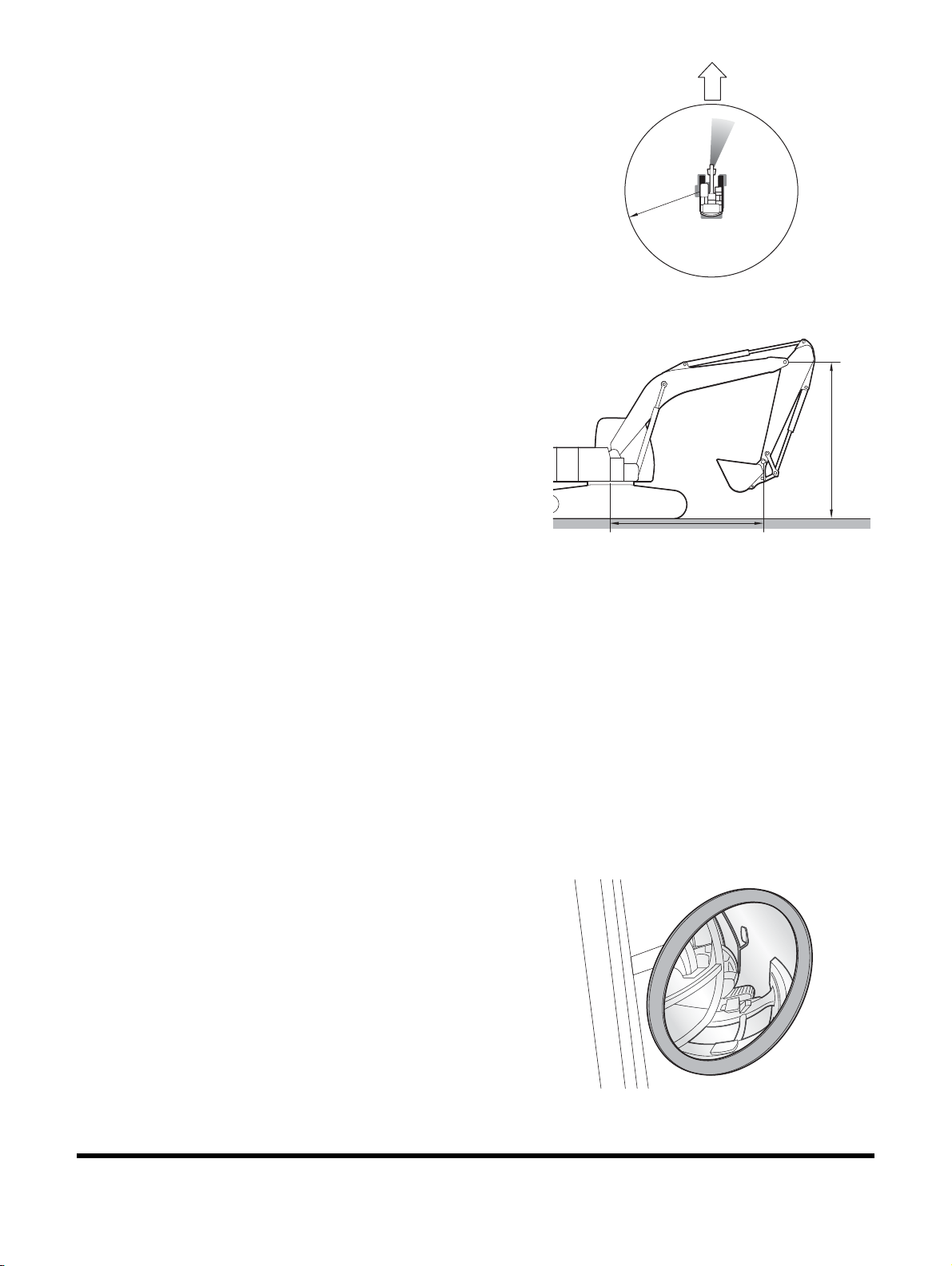
Figure 28 ~ Figure 30 provide an approximate visual indication
of the areas at ground level inside a radius of 12 m (39' 4") from
the operator of significant restricted visibility for various machine
configurations.
Figure 31 provides the position of the attachment and equipment
in the Travel position.
• Visible areas without visual aids at the ground level
• Visible areas with rear CCTV and mirrors
DX225LC-5
Safety
1-39
Page 58
• Visible areas with side/rear CCTV and mirrors
12 m (
4
72 in)
F
W
D
DS1801383
Figure 30
Figure 31
DS1801222
Figure 32
• Machine travel position
–A is 5.3 m (17' 5") from swing center to bucket pin
–B is 4.2 m (13' 9") from ground to arm pin
B
Mirror Adjustment
Frequently ensure the mirrors are directed properly.
• Park the machine on a level surface.
• Lower the attachment to the ground.
• Lower the safety lever to the LOCK position.
• Stop the engine.
• Use the machine access system.
NOTE: You may need hand tools to adjust certain types of
mirrors.
1. Front mirror on the cabin (1)
If equipped, adjust the front mirror on the cabin (1, Figure
27) so the front of the right track can be seen from the
operator seat.
A
DS1801218
1-40
DX225LC-5Safety
Page 59

2. Front mirror on the cabin (2)
DS1801380
Figure 33
If equipped, adjust the front mirror on the cabin (2, Figure
27) so the front of the left side can be seen from the
operator seat.
3. Additional mirrors other than Figure 27
If equipped, adjust the mirrors whenever you change
operators and ensure the mirrors are in proper working
conditions.
Work Site Rules
• If visibility cannot be sufficiently assured, use a flagman.
The operator should pay careful attention to signals and
follow instructions from flagman.
• Signals should only be given by one flagman.
• When working in dark places, turn "ON" work lights and
front lights on the machine. Set up additional lighting in
area.
• Stop operations if there is poor visibility, such as fog, snow,
rain, or sandstorms.
• Check mirrors and rear view camera (if equipped) on
machine before starting operations. Clean off any dirt and
adjust view for good visibility.
When operating or traveling during poor visibility conditions,
follow the preceding work site rules.
It may not be possible to adjust all visual aids to see all the way
around the machine. Therefore, additional precautions such as
flagman, barricades, etc., must be taken to keep other personnel
out of the work area.
DX225LC-5
Safety
1-41
Page 60

Boost Starting or Charging Engine
Batteries
Follow these instructions to prevent an explosion or fire when
connecting booster cables to batteries:
• Turn "OFF" all electric equipment before connecting leads
to battery. This includes electric switches on battery
charger or battery booster equipment.
• When boost starting from another machine or vehicle do
not allow two machines to touch. Wear safety goggles and
gloves while battery connections are made.
• 24 volt battery units consisting of two series connected 12
volt batteries have a cable connecting one positive (+)
terminal on one of the 12 volt batteries to a negative (-)
terminal on the other battery. Booster or charger cable
connections must be made between the nonseries
connected positive (+) terminals and between the negative
(-) terminal of the booster battery and metal frame of the
machine being boosted or charged. The final booster cable
connection, at metal frame of the machine being charged
or boost started, must be as far away from the batteries as
possible. Refer to
on page 3-12, for proper procedure in this manual.
"Starting Engine with a Booster Cable"
• Connect positive (+) cable first when installing cables and
disconnect negative (-) cable first when removing them.
1-42
DX225LC-5Safety
Page 61

Starting Engine
Figure 34
EX1301192
Figure 35
Only operate the machine from the operator's seat with your
seat belt fastened.
Only operate controls while engine is running.
Check for proper operation of all controls and all protective
devices while you operate the machine slowly in an open area.
• Read and understand control pattern before operating.
Check that movement of the machine matches display on
control pattern label. If it does not match, replace it
immediately with correct control pattern label.
• Check operation of work equipment, travel system and
swing system.
• Check for any problem with machine. Check for unusual
sounds, vibration, heat, odor, or improper readings from
gauges. Check for any oil or fuel leaks.
• If any problem is found, stop operation and perform repairs
immediately.
Do not use cellular telephones inside operator's cabin when
driving or operating the machine.
When operating the machine, do not extend your hands or head
out of window.
The boom and arm linkage can allow work tool or attachment to
contact undercarriage or cabin. Be aware of position of work
tool.
• Do not attempt to start engine by short-circuiting engine
starting circuit. This can result in death or serious injury, or
fire.
• When starting engine, sound horn as a warning to alert
personnel in the work area.
If there is a warning tag or "DO NOT OPERATE" tag hanging
from work levers (joysticks) or travel control levers, do not start
engine or move levers.
• Prevent personnel from walking or standing under raised
boom, unless it is properly supported.
NOTE: When starting engine in cold temperatures, "white
engine exhaust smoke" from the tail pipe can occur
until engine reaches normal operating temperatures.
Also, a white residue, because of water vapor inside
engine, can form at the engine oil fill location. These
conditions will not affect engine performance or
damage the engine or other exhaust system
components.
DX225LC-5
Safety
1-43
Page 62

Swinging or Traveling
Figure 36
As a machine operator, you should know and follow local, state
and federal laws and regulations when operating on public roads
or highways.
It is important to keep in mind that the machine, in comparison
with the rest of traffic, is a slow moving and wide vehicle which
can cause traffic delays. Pay attention to traffic behind you and
allow traffic to pass you.
Before operating the machine or work equipment, always
observe the following precautions to prevent death or serious
injury.
• When changing travel direction from forward to reverse or
from reverse to forward, reduce speed and stop machine
before changing travel direction.
• Sound horn to alert people in area.
• Check that there is no one in area around machine. There
are restricted visibility areas behind machine so, if
necessary, swing upper structure slowly to check that there
is no one behind machine before traveling in reverse.
• When operating in areas with poor visibility, designate a
flagman to direct work site traffic.
EX1400131
• Keep unauthorized personnel away from turning radius or
travel path of the machine.
Be sure to observe above precautions even if a travel alarm or
mirrors are installed.
• Check that travel alarm works properly and that mirrors are
clean, not damaged and properly adjusted.
• Always latch door and windows of operator's cabin in
position (open or closed).
• On work sites where there is a hazard of flying or falling
objects, or of objects entering operator's cabin, check that
door and windows are securely closed. Install additional
guards, if work site application requires them.
DX225LC-5Safety
1-44
Page 63

Never turn starter switch to "O" (OFF) position when traveling.
EX1300681
40 - 50 cm (16 - 20 in.)
Travel Position
Figure 37
This can lead to a loss of steering control.
Do not operate attachments while traveling.
Do not change selected travel mode (FAST/SLOW) while
traveling.
Never travel over obstacles or excessive slopes that will cause
machine to tilt severely. Avoid any slope or obstacle that can
cause machine to tilt 10° or more to right or left, or 30° or more
from front to rear.
Do not operate steering controls suddenly. Work equipment can
hit ground and this can damage machine or structures in area.
When traveling on rough ground, travel at low speed, and avoid
sudden changes in direction.
Always operate within permissible water depth. Permissible
water depth is up to centerline of upper track roller(s).
When passing over bridges or structures on private land, check
that structure is strong enough to support weight of machine.
Before traveling on public roads, check with appropriate
authorities and follow their instructions.
Never exceed maximum permitted load for bridges.
Always operate machine with idler wheels to front under cabin
and drive sprockets to rear.
Know permitted ground pressure. Ground pressure of the
machine may change depending on attachment and load.
Keep height and length of attachment in mind.
DX225LC-5
Safety
1-45
Page 64

Lifting and Digging
The operator is responsible for any load carried when traveling
on public roads and while working with the machine.
• Keep loads secure so they do not fall off while operating.
• Do not exceed maximum load for the machine. Machine
operation will be affected when center of gravity changes,
caused by extended loads and different attachments.
To lift loads safely when in digging mode, the following must be
evaluated by the operator and work site crew.
• Condition of ground support.
• Excavator configuration and attachments.
• Weight, lifting height and swing radius.
• Safe rigging of load.
• Proper handling of suspended load.
Always watch load. Bring load close to the machine before
traveling any distances or swinging load.
Lifting capacity decreases as load is moved further from the
machine.
Set tracks at right angles to road shoulder or drop-off with
sprocket at rear when performing operations to make it easier to
move away from the work area.
Do not suddenly lower, swing, or stop work equipment.
• Do not move bucket over head of other personnel or over
the operator's seat of dump trucks or other hauling
equipment. The load may spill or bucket can hit dump truck
causing property damage or cause death or serious injury.
1-46
DX225LC-5Safety
Page 65

Operation on Slopes
Figure 38
EX1300691
20 - 30 cm (8 - 12 in)
20 - 30 cm (8 - 12 in)
Figure 39
If the machine has to be used on a slope, pile soil to make a
platform that will keep the machine as horizontal as possible.
Improper traveling on steep slopes could result in machine
tipping, roll-over or sliding down the slope. Always fasten your
seat belt.
When possible, operate machine up slopes and down slopes.
Avoid operating machine across slope.
On hills, banks or slopes, carry bucket approximately 20 ~ 30 cm
(8 - 12
in) above ground. In case of an emergency, quickly lower
bucket or work tool to ground to help stop machine.
Do not travel on grass, fallen leaves, or wet steel plates. Even
slight slopes can cause machine to slide down a slope. Travel at
low speed and make sure that the machine is always traveling
directly up or down slope.
Do not change travel direction on a slope. This could result in
tipping or sliding sideways of machine.
Improper operation when working on slopes can cause a tip
over. Use caution when swinging or operating work equipment
on slopes.
Do not swing work equipment from uphill side to downhill side
when bucket is loaded. This could cause machine to tip or
roll-over.
In addition, lower bucket as far as possible, keep it pulled into
front, and keep swing speed as slow as possible.
If the machine begins to slide down on a grade, immediately
dump load and turn the machine downhill.
Be careful to avoid any ground condition which could cause the
machine to tip. Tipping can occur when you work on hills, on
banks, or on slopes. Tipping can also occur when you cross
ditches, ridges, or travel over unexpected obstructions.
Keep the machine under control. Do not overload the machine
beyond capacity.
• When traveling up a steep slope, extend work equipment
to front to improve balance, keep work equipment
approximately 20 ~ 30 cm (8 ~ 12
in) above ground, and
travel at low speed.
EX1300682
• Do not turn on slopes or travel across slopes. Always go
down to a flat place to change position of the machine,
then travel backup the slope again.
DX225LC-5
Safety
1-47
Page 66

Towing
Figure 40
To prevent death or serious injury when towing, always do the
following:
• Follow the instruction given in this manual.
• When performing preparation work for towing with two or
more personnel, determine signals to use and correctly
follow these signals.
• Always attach wire rope onto left and right hooks and
secure in position.
• If engine on problem machine will not start or there is a
failure in brake system, always contact your DOOSAN
distributor.
• Never go between towing machine and towed machine
during towing operation.
• Do not perform towing on steep slopes, so select a place
where slope is gradual. If there is no place where slope is
gradual, perform operations to reduce angle of slope
before starting towing operation.
• When towing a machine, always use a wire rope with a
sufficient towing capacity.
Cloth
Towing Wire
Towing Wire
• Do not use a wire rope that is kinked or frayed, or a wire
rope with any loss of diameter. Wear leather gloves when
handling a wire rope.
• Do not use lightweight towing hook for towing another
machine.
• Make sure that towing eyes and towing devices are
adequate for towing loads.
• Only connect wire rope to a drawbar or to a hitch.
• Operate the machine slowly and be careful not to apply
any sudden load to wire rope.
Towing Wire
EX1400132
DX225LC-5Safety
1-48
Page 67

Attachment
EX1400133
Figure 41
Never let anyone ride on any work attachment, such as bucket,
crusher, grapple, or clamshell (grab bucket). This creates a
falling and crushing hazard, and can result in death or serious
injury.
The clamshell, grapple, or magnet can swing in all directions.
Move work levers (joysticks) in a continuous motion. Failure to
move work levers (joysticks) in a continuous motion can cause
clamshell, grapple, or magnet to swing into cabin or into a
person in work area. This can result in death or serious injury.
• When using a fork or grapple, do not attempt to pick up an
object with its tips. This could damage the machine or
cause personal injury, if picked-up object slips off
attachment.
• Do not use impact force of work equipment for demolition
work. This could damage work equipment, cause broken
materials to fly off or tipping. This could result in death or
serious injury.
• Do not use work equipment or swing mechanism to pull
load in any direction. This could cause the work equipment
to move suddenly if the load releases and can result in
death or serious injury.
Equipment Lowering with Engine Stopped
Before lowering any equipment with the engine stopped, clear
the area around the equipment of all personnel and bystanders.
The procedure to use will vary with the type of equipment to be
lowered. Keep in mind most systems use a high-pressure fluid
or air to raise or lower equipment. The procedure can cause
high-pressure air, or hydraulic pressure, or some other media to
be released to lower the equipment.
DX225LC-5
Safety
1-49
Page 68

Engine Stop
Figure 42
Figure 43
Turn engine starter switch to "O" (OFF) position and remove
engine starter switch key.
Before lowering any equipment with engine stopped, clear area
around equipment of all personnel and bystanders. This
procedure will cause high-pressure air or hydraulic pressure to
be released to lower equipment.
Do not stop engine immediately after the machine has been
operated under load. This can cause overheating and
accelerated wear of engine components.
After the machine is parked, allow engine to run for five minutes
before stopping the engine. This allows hot areas of engine to
cool gradually.
• Do not leave operator's seat when there is a raised load.
Parking Machine
Avoid making sudden stops, or parking machine wherever it
happens to be at end of workday. Park machine on firm and
level ground away from traffic and away from high walls,
drop-offs and any area of potential water accumulation or runoff.
If parking on inclines is unavoidable, block crawler tracks to
prevent movement. Lower bucket or other working attachment
completely to ground, or to an overnight support saddle. To
prevent unintended or accidental movement.
120
Block
When parking on public roads, provide fences, signs, flags, or
lights, and put up any other necessary signs to ensure that
passing traffic can see machine clearly. Park machine so
machine, flags, signs and fences do not obstruct traffic.
After front attachment has been lowered to an overnight storage
position and all switches and operating controls are in "OFF"
position, safety lever must be moved to "LOCK" position. This
will disable all pilot control functions.
Always close door of operator's cabin and lock all equipment to
prevent any unauthorized person from operating the machine.
The hydraulic system remains pressurized, provided
accumulator, is charged even when engine is not running.
Accumulator pressure should decrease in a short time
(approximately one minute). While hydraulic system maintains a
charge, hydraulic work tools and machine controls remain
functional.
Machine movement will occur if any controls are moved. This
can result in death or serious injury.
Always move safety lever to "LOCK" position before stopping off
engine or immediately after engine stops running.
Unlock
Lock
EX1401035
EX1300684
DX225LC-5Safety
1-50
Page 69

Preservation/Storing Machine
Perform the following if storing excavator for more than one
month.
Conditions Maintenance Required
Cleaning Pressure wash undercarriage and track assemblies. Inspect for damage or
loose or missing parts.
Lubrication Perform all daily lubrication procedures.
Apply a coating of light oil to exposed plated metal surfaces, such as hydraulic
cylinder rods, etc.
Apply a coating of light oil to all control linkages and control cylinders (control
valve spools, etc.)
Battery Turn "OFF" the battery disconnect switch.
Cooling System Inspect coolant recovery tank to make sure that antifreeze level in system is at
correct level.
Every 90 days, use a hydrometer to measure protection level of coolant. Refer to
"Antifreeze Concentration Tables" on page 4-92, to determine amount of
protection cooling system requires. Add coolant as required.
Hydraulic System Once a month, start engine and follow procedures in "Hydraulic System
Warm-up" on page 3-13, listed in this manual.
1. Complete the preceding steps.
2. Wash machine and touch up paint finish to avoid rusting.
3. Treat exposed parts with antirust agent, lubricate machine
thoroughly and apply grease to unpainted surfaces like
lifting and tilting cylinders etc.
4. Fill fuel tank and hydraulic oil tank to "FULL" marks.
5. Cover exhaust pipe (parking outside).
6. Make sure that coolant is at proper concentration for
expected lowest temperatures.
7. Park machine on level, firm ground where there is no risk
of freezing, landslide or flooding. Avoid parking machine on
a slope.
Keep in mind that theft and burglary risk can be minimized
by:
• Removing starter key when the machine is left
unattended.
• Locking doors and covers after working hours.
• Turning off electrical current with battery disconnect
switch.
• Park machine where risk of theft, burglary and
damage is minimized.
• Removing valuables from cabin such as cellular
phone, computer, radio and bags.
See "Long Term Storage" on page 3-82, for more information.
DX225LC-5
Safety
1-51
Page 70

Check After Long-term Parking
• All oil and fluid levels.
• Tension of all belts.
• Air pressure.
• Air cleaner.
• Batteries and electrical connections.
• Lubricate all greasing points.
• Wipe off grease from piston rods.
• Inspect for signs of nests (i.e. birds, rodents, etc.)
• Inspect safety labels (decals). Replace if damaged, worn,
or missing.
1-52
DX225LC-5Safety
Page 71

MAINTENANCE
Improper operation and maintenance can result in death or
serious injury. Read manual and safety decals before operating
or maintaining the machine. Follow all instructions and safety
messages.
WARNING
AVOID DEATH OR SERIOUS INJURY
Follow instructions before operating or servicing machine.
Read and understand the Operation & Maintenance Manual
and signs (decals) on machine. Follow warnings and
instructions in the manuals when making repairs,
adjustments or servicing. Check for correct function after
adjustments, repairs or service. Untrained operators and
failure to follow instructions can result in death or serious
injury.
• Never service DOOSAN equipment without instructions.
• Always lower bucket and blade to ground before doing any
maintenance.
• Use correct procedure to lift and support excavator.
• Cleaning and maintenance are required daily.
• Welding or grinding painted parts must be done in well
ventilated areas.
• Wear a dust mask when grinding painted parts. Toxic dust
and gas can be produced.
• Vent exhaust to outside when engine must be running for
service.
• Exhaust system must be tightly sealed. Exhaust fumes are
hazardous and can cause death or serious injury.
• Stop and allow engine to cool and clean engine of
flammable materials before checking fluids.
• Never service or adjust machine with engine running
unless instructed to do so in this manual.
• Avoid contact with leaking hydraulic fluid or diesel fuel
under pressure. It can penetrate skin or eyes.
• Never fill fuel tank while engine running, while smoking, or
when near open flame.
• Keep body, jewelry and clothing away from moving parts,
electrical contact, hot parts and exhaust.
• Wear eye protection to guard from battery acid,
compressed springs, fluids under pressure and flying
debris when engines are running or tools are used. Use
eye protection approved for welding.
DX225LC-5
Safety
1-53
Page 72

• Lead-acid batteries produce flammable and explosive
gases.
• Keep arcs, sparks, flames and lighted tobacco away from
batteries.
• Batteries contain acid which burns eyes or skin on contact.
• Wear protective clothing. If acid contacts body, flush well
with water. For eye contact flush well and get immediate
medical attention from a physician familiar with this injury.
• The maintenance procedures which are given in this
manual can be performed by the owner or operator without
any specific technical training. Maintenance procedures
which are not in this manual must be performed ONLY BY
QUALIFIED SERVICE PERSONNEL. Always use genuine
DOOSAN replacement parts.
• Only authorized personnel should service and repair the
machine. Do not allow unauthorized personnel into work
area.
• Lower work equipment and stop engine before performing
maintenance.
• Park machine on firm and level ground.
• Turn starter switch to "ON' position and keep safety lever in
"UNLOCK" position. Cycle work levers (joysticks) back and
forth, left and right at full stroke 2 to 3 times to eliminate
remaining internal pressure in hydraulic circuit.
Then move safety lever to "LOCK" position.
• Check that battery relay is "OFF" and main power is shut
off. (Wait for approximately one minute after turning "OFF"
engine starter switch key and press horn switch. If horn
does not sound, the main power is shut off.)
• Put blocks under track to prevent the machine from
moving.
• To prevent injury, do not perform maintenance with engine
running. If maintenance must be done with engine running,
perform maintenance with at least two workers and do the
following:
– One worker must always sit in the operator's seat and
be ready to stop engine at any time. All workers must
maintain contact with other workers.
– When maintenance operations are near fan, fan belt,
or other rotating parts, there is a potential hazard of
being caught in rotating parts. Keep hands and tools
away.
• Never drop or insert tools or other objects into rotating fan
or fan belt. Parts can break off and hit someone.
• Do not touch any control levers or control pedals. If any
control levers or control pedals must be operated, always
give a signal to other workers and instruct them to move
away.
1-54
DX225LC-5Safety
Page 73

• When performing maintenance of engine and you are
Figure 44
exposed to engine noise for long periods of time, wear
hearing protection while working.
• If noise from the machine is too loud, it can cause
temporary or permanent hearing problems.
• Do not smoke when you service an air conditioner or if
refrigerant gas is present.
• Inhaling fumes either from a flame or gas from a cigarette
that has contacted air conditioner refrigerant can cause
death or serious injury.
• Never put maintenance fluids into glass containers.
Drain all liquids into a suitable containers.
• Unless instructed otherwise, perform maintenance with
equipment in servicing position. Refer to this manual for
procedure for placing equipment in servicing position.
Warning Tag
Alert others that service or maintenance is being performed by
attaching a "DO NOT OPERATE" warning tag to the operator's
cabin controls – and other machine areas, if required. Use of a
chain or cable to keep the safety lever in the fully lowered
"LOCK" position, complies with OSHA's lockout requirements.
"DO NOT OPERATE" warning tags, are available from your
DOOSAN distributor.
• Always attach "DO NOT OPERATE" warning tag to work
equipment control lever in the operator's cabin to alert
others that you are performing service or maintenance on
the machine. Attach additional warning tags on the
machine, if necessary.
• Keep warning tags in tool box while it is not used. If there is
not tool box or in the owner manual storage pocket.
• If any other person starts engine, and operates control
levers or control pedals while you are performing service or
maintenance, it can result in death or serious injury.
Attach a "DO NOT OPERATE" warning tag to starter switch or to
controls before servicing or repairing equipment.
Warning tags are available from your DOOSAN distributor.
EX1301177
DX225LC-5
Safety
1-55
Page 74

Cleaning
Figure 45
Clean machine before performing inspection and maintenance.
If inspection and maintenance are done when machine is dirty, it
will become more difficult to locate problems, and you could slip
on steps and work platform areas and injure yourself.
When washing machine, do the following:
• Wear shoes with nonslip soles to prevent slipping and
falling.
• Wear safety goggles and protective clothing when washing
machine with high-pressure steam or water.
• Do not spray water directly on electrical components
(sensors, connectors). If water gets into electrical system,
it can cause operation problems.
• Pick up any tools or hammers that are laying in workplace.
Wipe up any grease or oil to prevent slippery substances,
that can cause tripping or slipping.
• When cleaning cabin top window which is made of
polycarbonate material, use tap water. Avoid use of
organic solvents for cleaning, such as benzene, toluene or
methanol. These solvents can cause a chemical reaction
that will dissolve and damage the window.
Proper Tools and Clothing
Only use tools that are intended for the type of service to be
done. Metal pieces from low quality or damaged tools, such as
chisels or hammers, can break off and hit a service person in the
eyes or face causing serious injury.
EX1400134
Disassembling Precautions
When using a hammer to remove pins, pins can fly out or metal
particles may break off. Always do the following:
• Hitting hard metal pins, bucket teeth, cutting edges or
bearings with a hammer, can cause metal pieces to break
or fly off resulting in serious injury. Always wear safety
goggles and leather gloves. Keep other personnel away.
Use of Lighting
When checking fuel, oil, battery electrolyte, window washer fluid,
or coolant, always use proper lighting equipment to prevent arcs
or sparks that could cause a fire or explosion resulting in death
or serious injury.
DX225LC-5Safety
1-56
Page 75

Fire and Explosion Prevention
Figure 46
FG018458
Figure 47
Fuels, most lubricants and some coolant mixtures are
flammable. Flammable fluids that are leaking or spilled onto hot
surfaces or onto electrical components can cause a fire resulting
in property damage or death or serious injury.
Store all fuels and all lubricants in properly marked and
approved containers and keep away from all unauthorized
personnel.
Store oily rags and other flammable material in a protective
container.
Tighten all fuel and oil caps.
Do not smoke while you refuel machine or while you are in a
refueling area.
Do not smoke in battery charging areas or in areas that contain
flammable material.
Clean all electrical connections and tighten all electrical
connections. Check electrical wires daily for wires that are loose
or frayed. Tighten all loose, and repair or replace all frayed,
electrical wires before operating machine.
Remove all flammable materials and debris from the engine
compartment, exhaust system components and hydraulic lines.
HDO1015I
DX225LC-5
Safety
1-57
Page 76

Burn Prevention
Figure 48
When checking radiator coolant level, stop engine, let engine
and radiator cool down, then check coolant recovery tank. If
coolant level in coolant recovery tank is near upper limit, there is
enough coolant in radiator.
Using gloves, loosen radiator cap slowly to release internal
pressure before removing radiator cap.
If coolant level in coolant recovery tank is below lower limit, add
coolant.
Cooling system conditioner contains alkali which can cause
personal injury. Do not allow alkali to contact skin, eyes, or
mouth.
Allow cooling system components to cool before draining
cooling system.
Hot oil and hot components can cause personal injury. Do not
allow hot oil or hot components to contact skin.
Vent hydraulic tank only after engine has been stopped and
hydraulic tank is cool. Using gloves, slowly tilt hydraulic tank air
breather to relieve pressure.
Relieve all pressure in hydraulic oil system, in fuel system, or in
cooling system before disconnecting any lines, hoses, fittings, or
related components.
Batteries give off flammable fumes that can explode and start a
fire.
Do not smoke while you are checking battery electrolyte level.
Electrolyte is an acid. Electrolyte can cause personal injury. Do
not allow electrolyte to contact skin or eyes.
Always wear safety goggles and face protection when working
with batteries.
haae2090
DX225LC-5Safety
1-58
Page 77

Rubber That Contains Fluorides
Observe extra great care when it is suspected that you may
have to handle rubber that contains fluorides.
Certain seals which have to withstand high operating
temperatures (e.g. in engines, transmissions, axles, hydraulic
motors and pumps) may be made from rubber that contains
fluorides, which, when exposed to high heat (fire), forms
hydrogen fluoride and hydrofluoric acid. This acid is very
corrosive and cannot be rinsed or washed off from the skin. It
causes very severe burns which take a long time to heal.
It usually means that damaged tissue must be surgically
removed. Several hours may pass after contact with the acid,
before any symptoms appear and therefore one is not given any
immediate warning. The acid may remain on the machine parts
for several years after a fire.
If swelling, redness or a stinging feeling appears and one
suspects that cause may be contact with heated rubber that
contains fluorides, contact a medical doctor immediately. If a
machine, or part of a machine, has been exposed to fire or
severe heat, it must be handled by specially trained personnel.
In all handling of machines after a fire, thick rubber gloves and
protective goggles must be used.
The area around a part which has been very hot and which may
be made of rubber that contains fluorides must be
decontaminated by thorough and ample washing with limewater
(a solution or suspension of calcium hydroxide, i.e. slaked lime
in water). After the work has been completed, the gloves must
be washed in limewater and then discarded.
DX225LC-5
Safety
1-59
Page 78

Rubber and Plastics
Polymer materials when heated, can form compounds that
create a health hazard and can harm the environment.
Scrapped rubber and plastics must never be burned. Extra
precautions must be taken when servicing machines that have
been in a fire or exposed to extreme heat.
If gas cutting or welding is to be done near such materials, the
following safety instructions must be followed:
• Protect the material from heat.
• Use protective gloves, protective goggles and an approved
respirator.
Waste Hazardous to the Environment
Painted parts or parts made of plastic or rubber which are to be
scrapped must never be burned, but must be taken care of by an
approved refuse handling plant.
Batteries, plastic objects and anything else which is suspected
of being dangerous to the environment must be taken care of in
an environmentally safe way.
Check List After Fire
When handling a machine which has been damaged by fire
or been exposed to intense heat, the following protective
measures must under all circumstances be followed:
Use thick, gloves made of rubber and wear goggles which are
certain to protect your eyes.
Never touch burned components with your bare hands, as there
is a risk that you may come into contact with melted polymer
materials. First wash thoroughly with plenty of limewater (a
solution or suspension of calcium hydroxide, i.e. slaked lime in
water).
As a precaution, seals (O-rings and other oil seals) should
always be handled as if they were made of rubber that contains
fluorides.
Treat skin, which is suspected of having touched burned rubber
that contains fluorides, with Hydrofluoric Acid Burn Jelly or
something similar. Seek medical advice. Symptom may not
appear until several hours afterwards.
Discard gloves, rags etc. which are suspected of having touched
burned rubber that contains fluorides.
1-60
DX225LC-5Safety
Page 79

Welding Repairs
IMPORTANT
When disconnecting or connecting connectors between
ECU and engine, or connector between ECU and the
machine, always disconnect the battery to prevent damage
to ECU.
If you do not follow this procedure, the ECU will be
damaged and/or the engine will not operate properly.
When performing welding repairs, perform welding in a properly
equipped place. Repairs must be performed by a qualified
welder. Welding operations, can create potential hazards,
including generation of gas, fire, or electric shock. Never let an
unqualified welder do welding.
A qualified welder must do the following:
• To prevent battery explosion, turn battery disconnect
switch to "OFF" position.
• Disconnect the connector between ECU and machine, and
the connector between ECU and engine.
• Disconnect the negative (-) cable of battery.
• To prevent generation of gas, remove paint from location
of the weld.
• If hydraulic equipment, piping or component ports close to
them are heated, a flammable gas or mist could result in
an explosion or fire. To prevent this, protect and insulate
components from excessive heat.
• Do not weld on pipes or on tubes that contain flammable
fluids. Do not flame cut pipes or tubes that contain
flammable fluids. Before welding on pipes or tubes, or
before flaming cut pipes or tubes, clean them thoroughly
with a nonflammable solvent. Make sure pressure inside
pipes or tubes does not cause a rupture of the component
parts.
• If heat is applied directly to rubber hoses or piping under
pressure, they may suddenly break, so cover and insulate
them with a fireproof covering.
• Wear protective clothing.
• Make sure there is good ventilation.
• Remove all flammable objects and make sure a fire
extinguisher is available.
DX225LC-5
Safety
1-61
Page 80

Preparation for Electrical Welding On Body Structure
OFF
OFF
ON
OFF
ON
ON
EX1500481
Figure 49
EX1401352
Figure 50
To prevent damage to ECU by electrical welding, observe the
following procedures:
1. Turn battery disconnect switch to "OFF" position.
2. Disconnect the connector between ECU and machine, and
the connector between ECU and engine.
3. Disconnect the negative (-) cable of battery.
4. Proceed with welding.
5. After welding, connect the connector between ECU and
machine, and the connector between ECU and engine.
6. Connect the negative (-) cable of battery.
7. Clean battery compartment.
8. Turn battery disconnect switch to "ON" position.
9. Close battery compartment door.
Warning for Counterweight and Front
Attachment Removal
WARNING
AVOID DEATH OR SERIOUS INJURY
Removal of the machine counterweight, front attachment or
any other part can affect the stability of the machine. This
could cause unexpected movement, and result in death or
serious injury.
Never remove counterweight or front attachment unless the
upper structure is in-line with the lower structure.
Never rotate the upper structure once the counterweight or
front attachment has been removed.
1-62
DX225LC-5Safety
Page 81

Lock Inspection Covers
ARO1380L
Figure 51
When performing maintenance with inspection cover open, use
lock bar to secure cover and prevent accidental lowering of the
cover caused by wind or movement of the machine.
Working on Machine
When performing maintenance operations on machine, prevent
tripping and falling by keeping area around your feet clean and
free of objects and debris. Always do the following:
• Do not spill oil or grease.
• Do not leave tools laying around.
• Watch your step when walking.
• Never jump down from machine. When getting on or off
machine, use steps and handrails, and maintain a
three-point contact (both feet and one hand or both hands
and one foot) to support yourself.
• If job requires it, wear protective clothing.
• To prevent injury from slipping or falling, when working on
hood or covers, never stand or walk on areas except areas
equipped with nonslip pads.
• If it is necessary to work under raised equipment or the
machine, support work equipment and machine securely
with blocks and stands strong enough to support weight of
work equipment and machine.
• Do not work under the machine if track shoes are lifted off
ground and the machine is supported only with work
equipment. If any control levers are moved, or there is
damage to hydraulic system, work equipment or the
machine will suddenly drop causing death or serious injury.
DX225LC-5
Safety
1-63
Page 82

Accumulator
Figure 52
EX1400135
The pilot control system is equipped with an accumulator. For a
short period of time after engine has been stopped, accumulator
will store a pressure charge that allow hydraulic controls to be
activated. Activation of any controls will allow selected functions
to operate under force of gravity.
When performing maintenance on pilot control system, release
hydraulic pressure in system as described in
Accumulator" on page 4-97.
The accumulator is charged with high-pressure nitrogen gas. If it
is improperly handled it can explode causing death or serious
injury. Always observe the following precautions:
• Do not drill or punch holes in accumulator or expose it to
any flames, fire or external heat source.
• Do not weld on accumulator.
• When performing disassembly or maintenance of
accumulator, or when disposing of accumulator, charged
nitrogen gas must be properly released. Contact your
DOOSAN distributor for assistance.
• Wear safety goggles and leather gloves when working on
an accumulator. Hydraulic oil under pressure can
penetrate skin and result in death or serious injury. If fluid
enters skin or eyes, get immediate medical attention from a
physician familiar with this injury.
"Handling of
Compressed Air
• When cleaning filters, radiator or other components with
compressed air, there is a hazard of flying particles that
can result in serious injury.
• Always wear safety goggles, dust mask, leather gloves,
and other protective devices.
DX225LC-5Safety
1-64
Page 83

Track Tension Adjustments
HAOA110L
Figure 53
HDO1042L
Figure 54
Track adjusting systems use grease under high-pressure to
keep track under tension. Grease under high-pressure can
penetrate body and result in death or serious injury. Watch track
or track spring to see if track is being loosened.
NEVER LOOSEN track tension grease valve. To release
pressure from crawler frame track tension assembly, you should
NEVER attempt to disassemble track adjuster or attempt to
remove track tension grease valve assembly.
Keep your face and body away from grease valve. Refer to
"Track Tension" on page 4-98, for proper procedure in this
manual or Shop Manual.
Supports and Blocking for Work
Equipment
Do not allow weight or equipment loads to remain suspended
and unsupported.
Lower work group to ground before leaving operator's seat.
Do not use hollow, cracked or unsteady wobbling supports.
Do not work under any equipment supported only by a lifting
jack.
DX225LC-5
Safety
1-65
Page 84

High-pressure Lines, Tubes and Hoses
Figure 55
When inspecting or replacing high-pressure piping or hoses,
check to verify that pressure has been released from circuit.
Failure to release pressure can result in death or serious injury.
Release pressure as described in
page 4-97.
Always do the following:
• Wear eye protection and leather gloves.
• Fluid leaks from hydraulic hoses or pressurized
components can be difficult to see but has enough force to
pierce skin and can result in death or serious injury. Always
use a piece of wood or cardboard to check for suspected
hydraulic leaks. Never use your hands or expose your
fingers. Wear safety goggles.
• Do not bend high-pressure lines. Do not strike
high-pressure lines. Do not install lines, tubes or hoses that
are bent or damaged.
• Make sure that all clamps, guards and heat shields are
correctly installed to prevent vibration, rubbing against
other parts, and excessive heat during operation.
• Replace hose or components if any of the following
problems are found:
"Handling of Accumulator" on
EX1400129
– Damage or leakage from hose end fitting.
– Wear, damage, cutting of hose covering, or wire
braiding is exposed on any hose.
– Cover portion is swollen in any section.
– The hose is twisted or crushed.
– Foreign material is embedded in hose covering.
– Hose end is deformed.
– Connection fittings are damaged or leaking.
NOTE: Refer to "Hose In-service Lifetime Limit
(European Standard ISO 8331 and
EN982 (CEN))" on page 4-82, for additional
European regulations.
High-pressure is generated inside engine fuel lines when engine
is running. Before performing inspection or maintenance of fuel
line system, wait for at least thirty seconds after stopping engine
to let internal pressure drop and tip breather cap up to release
residual pressure.
Oil or fuel leaks from high-pressure hoses can cause fire or
improper operation, which can result in death or serious injury. If
any loose bolts are found, stop work and tighten to specified
torque. If any damaged hoses are found, stop operations
immediately and contact your DOOSAN distributor for
replacement parts.
DX225LC-5Safety
1-66
Page 85

Battery
Figure 56
Battery Hazard Prevention
Battery electrolyte contains diluted sulfuric acid and generates
hydrogen gas. Hydrogen gas is highly explosive, and improper
handling can cause death or serious injury, or fire. Do not allow
electrolyte to contact skin or eyes. Always wear safety goggles
and protective clothing when servicing batteries. Wash hands
after touching batteries and connectors. Use of acid-resistant
gloves is recommended. Always observe the following
precautions.
• Do not smoke or bring any flame near battery.
• When working with batteries, Always wear safety goggles,
protective clothing, and acid-resistant gloves.
• If you spill battery electrolyte on yourself or your clothes,
immediately flush area with water.
• If battery electrolyte gets into your eyes, flush them
immediately with large quantities of water and get
immediate medical attention from a physician familiar with
this injury.
• If you accidentally drink battery electrolyte, call a poison
prevention center immediately and get immediate medical
attention from a physician familiar with this injury.
• When cleaning top surface of battery, wipe it with a clean,
damp cloth. Never use gasoline, thinner, or any other
organic solvent or detergent.
• Tighten battery caps.
• If battery electrolyte is frozen, do not charge battery or start
engine with power from another source. This could cause
the battery to explode and start a fire.
• When charging battery or starting with power from another
source, let battery electrolyte thaw and check that there is
no leakage of battery electrolyte before starting operation.
• Always remove battery from machine before charging.
• Do not use or charge battery if battery electrolyte level is
below LOW LEVEL line. This can cause an explosion.
Periodically check battery electrolyte level and add distilled
water to bring electrolyte level to FULL LEVEL line.
• Before maintaining or working with batteries, turn starter
switch to "O" (OFF) position.
EX1400136
DX225LC-5
Safety
1-67
Page 86

Since there is a potential hazard that sparks could be generated,
always do the following:
• Do not let tools, rings or other metal objects make any
contact between battery terminals. Do not leave tools or
other metal objects lying near battery.
• When disconnecting battery terminals, wait for
approximately one minute after turning engine starter
switch key to "O" (OFF) position, and be sure to disconnect
grounding terminal; negative (-) terminal first. Conversely,
when connecting them, begin with positive (+) terminal and
then grounding (-) terminal, Make sure that all terminals
are connected securely.
• Flammable hydrogen gas is generated when battery is
charged. Remove battery from machine, take it to a well
ventilated place, and remove battery caps, before charging
it.
• After charging, tighten battery caps securely.
• After charging, secure battery back in machine.
When repairing or welding electrical system, wait for
approximately one minute after turning engine starter switch key
"OFF". Then disconnect negative (-) terminal of battery to stop
flow of electricity.
1-68
DX225LC-5Safety
Page 87

ENVIRONMENT AND
Figure 57
EX1300686
Figure 58
EX1300687
CIRCUMSTANCES
Work Site Areas Requiring Extra Caution
• Do not operate too close to edge of a quay, ramp, etc.
• Do not operate too close to edge of a steep slope or
drop-off. Take care when working in a place where
machine may tip over.
• Do not operate on soft ground or near riverbanks that could
collapse or where ground may not support weight of
excavator.
• Observe changes in ground and traction conditions after a
rain or other changes in weather.
Digging Under an Overhang
Do not dig work face under an overhang. This can cause
overhang to collapse and fall on top of the machine.
• Do not perform overhead demolition work. This can cause
broken objects and debris to fall on top of machine causing
death or serious injury, or property damage.
Deep Digging
Do not perform deep digging under front of machine. The ground
under machine may collapse and cause machine to fall resulting
in death or serious injury.
Working heavy loads on loose, soft or uneven ground, can cause
side load conditions resulting in a tip over and injury. Traveling
without a load or a balanced load may also be hazardous.
Never rely on lift jacks or other inadequate supports when work
is being done. Block tracks fore and aft to prevent any
movement.
Use machine only for its intended purpose. Using it for other
purposes will cause failures.
• Do not perform demolition work under machine. There is a
hazard that the machine may become unstable and tip
over.
• When working on or from top of buildings or other
structures, check if structure can support weight of
machine and attachment. If a building structure collapses,
this can cause death or serious injury.
DX225LC-5
Safety
1-69
Page 88

Drop-off or Edge
When working at edge of an excavation or near a drop-off, the
machine could tip over, which can result in death or serious
injury. Always fasten your seat belt. Check ground conditions of
work site before operating to prevent the machine from falling or
roll-over, and to prevent ground, stockpiles, or banks from
collapsing.
Do not travel too close to edge of a drop-off.
Poor Visibility
For good visibility, always do the following:
• When working in dark areas, attach working lights and
front lights to the machine. If necessary, set up additional
lighting at work site.
• Stop operations when visibility is poor, such as in fog, mist,
snow, and rain. Wait for visibility to improve before starting
operation.
To avoid hitting work equipment and damaging other property,
always do the following:
• When working in tunnels, on bridges, under electrical
wires, or when parking the machine or performing other
operations in places with limited height, be careful not to hit
and damage other equipment or property.
• To prevent hitting objects, operate machine at a slow
speed when working in confined spaces, indoors, or in
crowded areas.
• Do not swing bucket over the top of personnel or over
operator's cabin of dump truck.
Loose or Soft Ground
Do not operate on soft ground or near edge of drop-offs,
overhangs, and deep ditches. The ground can collapse because
of the weight of the machine causing the machine to fall or rollover.
Check ground conditions before beginning work with the
machine. If ground is soft, reposition the machine before
operating.
The excavated material must not be dumped too close to edge.
How far away from edge of trench excavated material must be
dumped depends on soil type and moisture content. If loose clay
is being excavated, place it at least 5 m (16 ft) away from edge.
If excavated material is dumped too close to edge, its weight can
cause a landslide.
Thawing of frozen ground, rain, traffic, piling and blasting are
other factors which increase risk of landslide. The risk also
increases on sloping ground. If it is not possible to dig a trench
and adequately slope its sides, always install shoring
equipment.
1-70
DX225LC-5Safety
Page 89

Loose ground may easily give way under weight of the machine.
Figure 59
EX1300688
When working on loose or unstable ground, it is important not to
dig too deep and to carefully reposition the machine. Do not
panic and do not raise bucket, if ground should begin to
collapse. Lower work equipment to improve stability of machine.
Never dig under machine, if there is a potential of causing a
landslide.
High-voltage Cables
Do not travel or operate machine near electrical cables or
overhead power lines. There is a hazard of electric shock, which
can cause property damage and result in death or serious injury.
The bucket or other attachment does not have to make physical
contact with power lines for current to cause an electrocution.
Use a spotter and hand signals to stay away from power lines
not clearly visible to operator. On work sites where machine may
operate close to electrical cables, always do the following:
• Remember that electrical voltage determines what the
minimum distance is to stay away from the power line. See
the following table for minimum distances when working
near electrical power lines. Electrical flashover can occur
and damage machine and cause death or serious injury.
Voltage Minimum Distance
6.6 kV 3 m (9' 10")
33.0 kV 4 m (13' 1")
66.0 kV 5 m (16' 5")
154.0 kV 8 m (26' 3")
275.0 kV 10 m (32' 10")
• Always contact the power company responsible before
beginning work near high voltage power lines.
DX225LC-5
Safety
1-71
Page 90

Underground Operation
Figure 60
Figure 61
EX1300690
1
If excavation is in an underground location or in a building, make
sure there is adequate overhead clearance, and adequate
ventilation.
Special equipment and engines may be required in some
countries. Contact your DOOSAN distributor for more
information.
Check that there is sufficient room for machine and load.
Move slowly.
Make sure that authorities or companies responsible for
underground cables, utilities, and electrical lines have been
contacted and that their instructions are followed. Also check
which rules apply to ground personnel regarding exposing
cables, utilities and electrical lines.
Consider all electrical cables as live.
Working in Water
IMPORTANT
EX1300689
Do not exceed maximum permissible water depth. The
water level must not reach higher than centerline of upper
track roller(s) (1,
After working in water, lubricate all lubrication points on
undercarriage, which have been underwater so water is
removed. Check that no water has entered travel gearboxes and
undercarriage components.
Figure 61).
Working in Contaminated Environment
When working within area which is contaminated or where there
is a health risk, check local regulations and contact your
DOOSAN distributor for assistance with identifying what
additional safety precautions need to be taken.
1-72
DX225LC-5Safety
Page 91

Operation in Extreme Conditions
Operation In Extreme Cold
In extremely cold weather, avoid sudden travel movements and
stay away from even slight slopes. The machine could slide
down the slope.
Snow accumulation could hide potential hazards and slippery
surfaces.
Warming up engine for a short period may be necessary to
avoid operating with sluggish or reduced working capacity. The
jolting shocks and impact loads caused by bumping or
bottoming boom or attachment could cause severe stress in
very cold temperatures. Reducing work cycle rate and workload
may be necessary.
If machine is to be operated in extremely cold weather
temperatures, certain precautions must be taken. The following
paragraphs detail checks to be made to be certain machine is
capable of operating at these temperatures.
1. Keep batteries fully charged to prevent freezing. If distilled
water is added to batteries, run engine at least one hour to
mix electrolyte solution.
When temperature drops below -10°C, efficacy of the
battery is reduced accordingly. Insulation of the battery
prevents reduction of efficacy, and supports improvement
of starting power of the starter.
WARNING
AVOID DEATH OR SERIOUS INJURY
Explosion of the battery can cause death or serious
injury. Never attempt to directly heat the battery with
open fire.
2. Keep engine in good mechanical condition for easy starting
and good performance during adverse weather.
3. Use engine oil with proper specifications for expected
temperatures. Refer to
Lubricants" on page 4-22, in this manual or Shop Manual
for details.
4. Always keep the fuel tank fully filled after completion of the
operation. Always drain water from the fuel tank before and
after the operation. In addition, check the water separator,
and drain it if required. The fuel filter, if frozen, may
interrupt the flow of fuel. Periodically remove water from
the fuel tank, drain water from the filter, and replace the
filter upon regular basis. To prevent fuel from being
clogged because of formation of wax in fuel, make sure
that wax formation point of fuel is lower than atmospheric
temperature.
"Table of Recommended
DX225LC-5
Safety
1-73
Page 92

WARNING
AVOID DEATH OR SERIOUS INJURY
Explosion of the fuel tank can cause serious injury or
death. Never attempt to directly heat the fuel tank with
open fire
5. Lubricate entire machine according to "Lubrication and
Service Chart" on page 4-18, in this manual or lubrication
chart on machine.
6. Start engine and allow it to reach normal operating
temperature before operating.
• If mud and ice collects and freezes on any of moving
• Operate hydraulic units with care until they have
• Check all machine controls and functions to be sure
7. An extra outer air filter must be kept in operator's cabin to
replace element that could become iced and cause
restricted airflow to engine.
.
parts while machine is idle, apply heat to thaw frozen
material before attempting to operate machine.
reached a temperature which enable them to operate
normally.
they are operating correctly.
8. Clean off all mud, snow and ice to prevent freezing. Cover
machine with a tarp if possible, keep ends of tarp from
freezing to ground.
Operation in Extreme Heat
Continuous operation of machine in high temperatures can
cause machine to overheat. Monitor engine and hydraulic
system temperatures and stop machine to let it cool, when
necessary.
1. Make frequent inspections and services of fan and
radiator. Check coolant level in radiator. Check grilles and
radiator fins for accumulation of dirt, debris and insects
which could block cooling passages.
• Formation of scale and rust in cooling system occurs
more rapidly in extremely high temperatures. Change
antifreeze each year to keep corrosion inhibitor at full
strength.
• If necessary, flush cooling system periodically to
keep passages clear. Avoid use of water with a high
alkali content which increases scale and rust
formation.
2. Check level of battery electrolyte daily. Keep electrolyte
above plates to prevent damage to batteries. Use a slightly
weaker electrolyte solution in hot climates. Batteries
self-discharge at a higher rate if left standing for long
1-74
DX225LC-5Safety
Page 93

periods at high temperatures. If machine is to stand for
several days, remove batteries and store in a cool place.
IMPORTANT
Do not store acid type storage batteries near stacks of
tires. Acid fumes can damage rubber.
3. Service fuel system as directed in "Check Fuel Level" on
page 4-30 and "Check for Leaks in Fuel System" on
page 4-30, of this manual. Check for water content before
filling fuel tank. High temperatures and cooling off cause
condensation in storage drums.
4. Lubricate as specified in "Lubrication and Service Chart"
on page 4-18, in this manual or Lubrication Decal on
machine.
5. Do not park machine in sun for long periods of time. If
possible, park machine under cover to protect it from sun,
dirt and dust.
A. Cover machine if no suitable shelter is available.
Protect engine compartment and hydraulics from dirt
and debris.
B. In hot, damp climates, corrosion will occur on all parts
of machine and will be accelerated during rainy
season. Rust and paint blisters will appear on metal
surfaces and fungus growth on other surfaces.
C. Protect all unfinished, exposed surfaces with a film of
preservative lubricating oil. Protect cables and
terminals with ignition insulation compound.
Apply paint or suitable rust preventive to damaged
surfaces to protect them from rust and corrosion.
Operation In Dusty and Sandy Areas
Operation of machine can cause dust in almost any area.
However, when in predominantly dusty or sandy areas,
additional precautions must be taken.
1. Keep cooling system fins and cooling areas clean. Blow
out with compressed air, if possible, as often as necessary.
WARNING
AVOID DEATH OR SERIOUS INJURY
Wear goggles when using compressed air to prevent
face or eye injury.
2. Use care when servicing fuel system to prevent dust and
sand from entering tank.
DX225LC-5
Safety
1-75
Page 94

3. Service air cleaner at frequent intervals, check air
restriction indicator daily and keep dust cup and dust valve
clean. Prevent dust and sand from entering engine parts
and compartments as much as possible.
4. Lubricate and perform services outlined on current
lubrication chart on machine and
Chart" on page 4-18. Clean all lubrication fittings before
applying lubricant. Sand mixed with lubricant becomes
very abrasive and accelerates wear on parts.
5. Protect machine from dust and sand as much as possible.
Park machine under cover to keep dust and sand from
damaging unit.
Operation in Rainy or Humid Conditions
Operation under rainy or humid conditions is similar to that as in
extreme heat procedures previously listed.
1. Keep all exposed surfaces coated with preservative
lubricating oil. Pay particular attention to damaged or
unpainted surfaces. Cover all paint cracks and chip marks
as soon as possible to prevent corrosive effects.
Operation in Saltwater Areas
"Lubrication and Service
Saltwater and saltwater spray is very corrosive. When operating
in saltwater areas, or in or around snow, observe the following
precautions:
1. When exposed to saltwater, dry machine thoroughly and
rinse with freshwater, as soon as possible.
2. Keep all exposed surfaces coated with preservative
lubricating oil. Pay attention to damaged paint surfaces.
3. Keep all painted surfaces in good repair.
4. Lubricate machine as prescribed on lubrication chart on
machine or
in this manual. Shorten lubricating intervals for parts
exposed to salt water.
5. Check operating controls to ensure proper functionality
and that they return to "NEUTRAL" when released.
"Lubrication and Service Chart" on page 4-18,
1-76
DX225LC-5Safety
Page 95

Operation at High Altitudes
ARO1770L
Figure 62
Operation instructions at high altitudes are the same as those
provided for extreme cold. Before operating at high altitudes,
engine fuel and air mixture may have to be adjusted according
to appropriate engine manual.
1. Check engine operating temperature for evidence of
overheating. The radiator cap must make a perfect seal to
maintain coolant pressure in cooling system.
• Perform warming-up operation thoroughly. If machine
is not thoroughly warmed up before control levers or
control pedals are operated, reaction of machine will
be slow.
• If battery electrolyte is frozen, do not charge battery
or start engine with a different power source. There is
a potential hazard that could cause a battery
explosion or fire.
• Before charging or starting engine with a different
power source, thaw battery electrolyte and check for
any leakage of electrolyte before starting.
Operation During Electrical Storms
During electrical storms, do not enter or exit machine.
• If you are off machine, keep away from machine until storm
passes.
• If you are in cabin, remain seated with machine stationary
until storm passes. Do not touch controls or anything
metal.
Exhaust Ventilation
Engine exhaust gases can cause unconsciousness, loss of
alertness, judgment and motor control. This can result in death
or serious injury.
Make sure there is adequate ventilation before starting engine in
any enclosed area.
Check for and be aware of any open windows, doors or
ductwork where exhaust may be carried, or blown by wind,
exposing others to hazardous exhaust gases.
Ventilation for Enclosed Area
If it is necessary to start engine within an enclosed area, or when
handling fuel, flushing oil, or paint; open doors and windows to
ensure that adequate ventilation is provided to prevent gas
poisoning.
Diesel engine exhaust contains products of combustion which
can be harmful to your health.
Always run engine in a well ventilated area. If you are in an
enclosed area, vent exhaust to outside.
DX225LC-5
Safety
1-77
Page 96

Asbestos Information
WARNING
AVOID DEATH OR SERIOUS INJURY
Avoid exposure to dust containing asbestos as it can cause
death or serious injury to the lungs and other organs
(mesothelioma, lung and other cancers, and asbestosis).
Asbestos dust can be HAZARDOUS to your health if it is inhaled.
Materials containing asbestos fiber can be present on work sites.
Breathing air that contains asbestos fiber can ultimately cause
serious or fatal lung damage or diseases such as mesothelioma,
lung and other cancers, and asbestosis. To prevent lung damage
from asbestos fiber, observe the following precautions:
• Use an approved respirator that is approved for use in an
asbestos-laden atmosphere.
• Use water for cleaning to keep down dust.
• Always observe any regulations related to work site and
working environment.
• Avoid brushing or grinding materials that contain asbestos.
• A vacuum cleaner that is equipped with a high efficiency
particulate air filter can also be used.
• Comply with applicable laws and regulations for workplace.
• Stay away from areas that might have asbestos particles in
air.
Silica Dust Information
WARNING
AVOID DEATH OR SERIOUS INJURY
Avoid exposure to dust containing crystalline silica
particles as it can cause serious injury to the lungs
(silicosis).
Cutting or drilling concrete containing sand or rock containing
quartz can result in exposure to silica dust. Do not exceed
Permissible Exposure Limits (PEL) to silica dust as determined
by OSHA or other work site rules, laws and regulations. Use a
respirator, water spray or other means to control dust. Silica dust
can cause lung disease and is known to the state of California to
cause cancer.
1-78
DX225LC-5Safety
Page 97

Disposal of Hazardous Materials
Figure 63
FG009156
Physical contact with used motor oil or gear oil could create a
health risk. Wipe oil from your hands promptly and wash off any
remaining residue.
Used motor oil or gear oil is an environmental contaminant and
should only be disposed of at approved collection facilities. To
prevent pollution of environment, always do the following:
• Never dump waste oil in a sewer system, rivers, etc.
• Always put drained oil from your machine in approved, leak
proof containers. Never drain oil directly onto ground.
• Obey appropriate laws and regulations when disposing of
harmful materials such as oil, fuel, solvent, filters, and
batteries.
Improperly disposing of waste can threaten environment.
Potentially harmful fluids must be disposed of according to local
regulations.
Use all cleaning solutions with care. Report all necessary
repairs.
Sound
Sound Level Information: Hearing protection may be required
when machine is operated with an open operator station for
extended periods or in a noisy environment.
Sound pressure level (LpA) at operator
position (Measurement according to ISO 6396)
Sound power level (LwA) around the machine
(Measurement according to 2000/14/EC with
applicable appendices and measuring method
according to ISO 6395)
70 dB(A)
103 dB(A)
DX225LC-5
Safety
1-79
Page 98

Vibration Information
NOTE: The level of vibration is influenced by many different
parameters such as operator training, job site
organization, weather, material, environment,
machine type, machine and seat suspension system,
attachments, and condition of the machine.
Measurements are obtained on a representative machine, using
measuring procedures as described in the following standards:
ISO 2631/1, ISO 5349, and SAE J1166.
Vibration levels were given consideration in accordance with
uncertainty (K) determined to manufacturer.
Hand/Arm Vibration Level
The vibration total value to which the hand-arm system is
subjected, is less than 2.5 m/s
2
.
Whole Body Vibration Level
The highest root mean square value of weighted acceleration to
2
which the whole body is subjected, is less than 0.5 m/s
.
Guidelines for Use and Working Conditions of Earth-moving Machinery to Reduce Vibration Levels (ISO/TR 25398 Annex E)
Properly adjusting and maintaining machines, operating
machines smoothly, and maintaining the terrain conditions can
reduce whole-body vibrations. The following can help the users
of earth-moving machinery reduce whole-body vibration levels.
1. Use the right type and size of machine, equipment, and
attachments.
2. Maintain machines according to the manufacturer's
recommendations: (for wheeled machine)
• Tire pressure;
• Brake and steering systems;
• Controls, hydraulic system and linkages.
3. Keep the terrain where the machine is working and
travelling in good condition:
• Remove any large rocks or obstacles;
• Fill any ditches and holes;
• Provide machines and schedule time to maintain
terrain conditions.
4. Use a seat in conformance with ISO 7096 and keep the
seat maintained and adjusted:
• Adjust the seat and suspension for the weight and
size of the operator;
• Inspect and maintain the seat suspension and
adjustment mechanisms.
1-80
DX225LC-5Safety
Page 99

5. Steer, brake, accelerate, shift gears, and move the
attachments smoothly. (for wheeled machine)
6. Adjust the machine speed and travel path to minimize the
vibration level:
• Drive around obstacles and rough terrain conditions;
• Slow down when it is necessary to go over rough
terrain.
7. Minimize vibrations for long work cycle or long distance
travelling: (for wheeled machine)
• Use machines equipped with suspension systems;
• Use lift arm suspensions on wheel loaders;
• If no suspension system is available, reduce speed to
prevent bouncing;
• Haul machines long distances between worksites.
8. Back pain associated with whole-body vibrations can be
caused by other risk factors. To minimize the risk of back
pain:
• Adjust the seat and controls to achieve good posture;
• Adjust the mirrors to minimize twisted posture;
• Provide breaks to reduce long periods of sitting;
• Avoid jumping down from the cab or access system;
• Minimize repeated handling and lifting of loads;
• Minimize any shocks and jolts during sports and
leisure activities.
DX225LC-5
Safety
1-81
Page 100

1-82
DX225LC-5Safety
 Loading...