

Doosan A2300, D15S-5, G18S-5, G20SC-5, GC15S-5 Service Manual
...
SB4106E01
Service Manual
A2300 Diesel Engine
D15S-5, D18S-5, D20SC-5
G15S-5, G18S-5, G20SC-5
GC15S-5, GC18S-5, GC20SC-5


Important Safety Information
Most accidents involving product operation, maintenance and repair are caused by failure to observe basic
safety rules or precautions. An accident can often be avoided by recognizing potentially hazardous situations
before an accident occurs. A person must be alert to potential hazards. This person should also have the
necessary training, skills and tools to perform these functions properly.
Read and understand all safety precautions and warnings before operating or performing lubrication,
maintenance and repair on this product.
Basic safety precautions are listed in the “Safety” section of the Service or Technical Manual. Additional safety
precautions are listed in the “Safety” section of the owner/operation/maintenance publication.
Specific safety warnings for all these publications are provided in the description of operations where hazards
exist. WARNING labels have also been put on the product to provide instructions and to identify specific
hazards.
If these hazard warnings are not heeded, bodily injury or death could occur to you or other persons. Warnings
in this publication and on the product labels are identified by the following symbol.
WARNING
Improper operation, lubrication, maintenance or repair of this product can be dangerous and could
result in injury or death.
Do not operate or perform any lubrication, maintenance or repair on this product, until you have read
and understood the operation, lubrication, maintenance and repair information.
Operations that may cause product damage are identified by NOTICE labels on the product and in this
publication.
DOOSAN cannot anticipate every possible circumstance that might involve a potential hazard. The warnings
in this publication and on the product are therefore not all inclusive. If a tool, procedure, work method or
operating technique not specifically recommended by DOOSAN is used, you must satisfy yourself that it is
safe for you and others. You should also ensure that the product will not be damaged or made unsafe by the
operation, lubrication, maintenance or repair procedures you choose.
The information, specifications, and illustrations in this publication are on the basis of information available at
the time it was written. The specifications, torques, pressures, measurements, adjustments, illustrations, and
other items can change at any time. These changes can affect the service given to the product. Obtain the
complete and most current information before starting any job. DOOSAN dealers have the most current
information available.
1


A Series Diesel Engine Index
Index
Introduction
About the Manual ...................................................... 5
How to Use the Manual .............................................5
Generic Symbols....................................................... 6
Definition of Terms.....................................................7
Illustrations................................................................ 8
General Engine Information
External Engine Components ....................................9
Engine Specifications...............................................11
Troubleshooting Logic
Engine Diagrams .................................................... 12
Problem Isolation and Correction ........................... 12
Troubleshooting Logic(List of Symptoms)............... 13
Coolant System
Cooling System Components and Flow...................53
Pressure Caps .........................................................56
Water(Coolant) Pump...............................................57
Thermostat...............................................................60
Gauges, Overfueling and Laoding...........................61
Cooling System Replacement Procedures..............62
Belt Tensioner Replacement................................... 62
Fan Pulley Replacement ......................................... 62
Fan Hub Replacement............................................ 63
Water Pump Replacement.......................................64
Cup Plug Replacement............................................67
Fuel System
Fuel System Components and Flow........................68
Fuel System Malfunction Diagnosis .........................69
Air in the Fuel System..............................................70
Fuel Water Separator/Filter Unit..............................71
Injection Pump .........................................................72
Governor Malfunctions.............................................72
Fuel Control Lever TRavel and Adjustment.............73
VE Pump Adjustment Screws..................................73
Manual Shut Down Levers .......................................74
Advance Timing Mechanism....................................74
Electrical Shut off Valves .........................................75
Injection Pump Timing..............................................77
High Pressure Fuel Line ..........................................78
Injectors....................................................................79
Fuel Drain Manifold..................................................81
Air System
Air System Flow.......................................................98
Diagnosing Air System Malfunctions........................99
Air Flow Restriction..................................................99
Damage from Non-Filtered Air...............................100
Pressure Side Air Leaks.........................................100
Exhaust Leaks........................................................101
Malfunctioning Turbocharger..................................101
Oil Consumption and Leaks ...................................102
Turbocharger Noise ...............................................103
Rotor Assembly Clearance Measure.....................104
Lubricating System
Lubricating System Flow........................................113
Lubricating Oil Pump..............................................113
Pressure Regulating Valve.....................................113
Oil Coolers..............................................................114
Oil Filters................................................................114
Oil Filters Bypass Valve..........................................114
Low Oil Pressure....................................................116
Oil Level .................................................................116
Oil Filter..................................................................117
Oil Gauge...............................................................117
Oil Suction Tube.....................................................117
Bearings and Oil Pump..........................................117
Incorrect Oil Pump..................................................118
Oil Dilution..............................................................118
Coolant Diluted Oil .................................................118
Fuel Diluted Oil.......................................................119
Oil Leaks................................................................123
Electrical System
Electrical System Description/Operation................134
Electrical System Spec. .........................................136
Starting Motor.........................................................137
Engine Cranking Speed Too Slow.........................139
Alternator................................................................140
Fuel Shut Off Valve Check.....................................143
Oil Pressure Switch................................................143
3

A Series Diesel Engine Index
Base Engine Components
Operation and Description .....................................148
Cylinder Head and Valve Train..............................149
Front Gear Housing and Gear Train......................150
Front Crankshaft Seal............................................150
Camshaft, Tappets and Push Rods.......................150
Flywheel Housing and Flywheel ............................151
Piston and Rod Assemblies...................................152
Crankshaft and Main Bearings...............................154
Oil Pan ...................................................................156
Base Engine Component.......................................156
Air and Fuel System...............................................157
Compression Check ...............................................158
Piston Ring Seal ....................................................158
Valce Sealing .........................................................158
Valve Seal Wear.....................................................160
Front Gear Housing and Gear TRain.....................161
Rocker Levers........................................................162
Piston and Rod Assembly ......................................163
Crankshaft and Main Bearings...............................165
Cylinder Block........................................................166
Flywheel Housing and Flywheel ............................166
Base Engine Componen Specifications .................168
Gear Train..............................................................169
Camshaft................................................................169
Tappets...................................................................169
Pistons ...................................................................170
Connecting Rod .....................................................171
Crankshaft..............................................................171
Cylinder Block........................................................171
Cylinder Bore .........................................................172
Base Engine Components .....................................173
Rocker Levers........................................................174
Rocker Levers Assembly .......................................179
Valve Clearance.....................................................179
Four Cylinder Engine .............................................179
Camshaft and Tappet .............................................180
Camshaft Inspection ..............................................181
Camshaft Bushing Inspection ................................182
Tappet Inspection ...................................................183
Gear Housing or Gasket........................................186
Flywheel Ring Gear and Rear Sel.........................187
Brass Drift Pin........................................................187
Flywheel.................................................................188
In Chassis Overhaul...............................................189
Cylinder Head Removal.........................................190
Main Bearing Preliminary Inspection .....................191
Main Bearing..........................................................194
Piston and Rod ......................................................196
Piston, Pin and Connecting Rod............................197
Piston Ring Gap.....................................................202
Piston Rings...........................................................202
Piston and Rod Assembly ......................................204
Cylinder Head and Gasket .....................................207
Cylinder Head.........................................................211
Valves.....................................................................214
Valve Seats............................................................216
Cylinder Head ........................................................220
Hydraulic Pump Drive Gear and Shaft...................221
Balancer-Remove ..................................................221
Balancer-Install ......................................................222
Engine Replacement and Testing
Engine Replacement ..............................................223
Engine Removal .....................................................224
Engine Installation ..................................................225
Engine Testing........................................................227
Specifications
General Engine......................................................228
Fuel System...........................................................228
Lubricating Oil System...........................................228
Cooling System......................................................229
Air Intake System...................................................229
Exhaust System.....................................................229
Electrical System....................................................229
Drive Belt Tension..................................................229
Capscrew Markings and Torque Values.................230
Fraction, Decimal, Millimeter Conversions.............233
Newton-Meter to Foot-Pound Conversions............234
Pipe Plug Torque Values........................................234
Weights and Measures-Conversion Factors ..........235
Special Tools
Special Tool List.....................................................237
4

Introduction
About the Manual
The procedures in this manual were developed for an in-chassis environment. The information has been grouped
by the main engine systems. The Table of Contents defines the systems. The index at the beginning of each
section subdivides the instructions for the various components of the system. Wrench sizes and special tools are
identified in the procedures as needed.
How to Use the Manual
The organization of this manual is based on the troubleshooting logic presented in Section 2. To fix a problem, find
the logic chart for the particular symptom. Follow the steps specified until the problem is corrected.
The left column of the charts indicates a probable cause. The right column provides a brief description of the
corrective action with a reference to the repair procedure or diagnostic discussion when appropriate.
The logic charts reflect three basic considerations:
1. Assumes the engine has provided satisfactory service prior to the problem.
2. Performing the easiest things first.
3. Most logical cause in descending order.
If the problem occurs with a new engine or after repair of the engine, the diagnostics discussion for each major
system will provide guidance for sorting out the cause of the problem.
A Series Diesel Engine Introduction
5
Generic Symbols
The following group of symbols has been used in this manual to help communicate the intent of the instructions.
When one of the symbols appears, it conveys the meaning defined below.
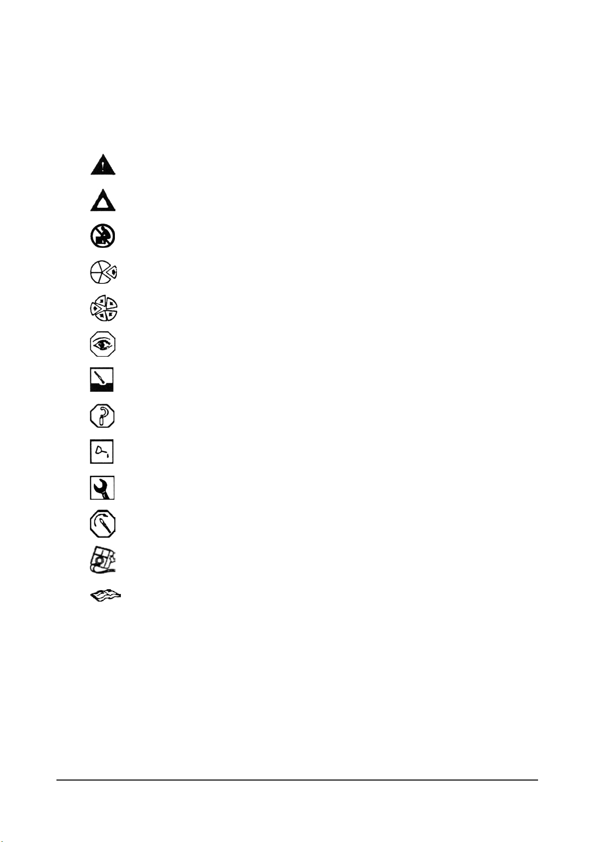
Warning – Serious personal injury or extensive property damage can result if the warning
instructions are not followed.
Causion – Minor personal injury can result or a part, an assembly or the engine can be
damaged if the caution instructions are not followed.
The component weighs 23kg [50lb] or more. To avoid personal injury, use a hoist or get
assistance to lift the component.
Indicates a REMOVAL or DISASSEMBLY step.
Indicates an INSTALLATION or ASSEMBLY step.
INSPECTION is required.
CLEAN the part or assembly.
PERFORM a mechanical or time MEASUREMENT.
LUBRICATE the part or assembly.
Indicates that a WRENCH or TOOL SIZE will be given.
TIGHTEN to a specific torque
PERFORM an electrical MEASUREMENT.
A Series Diesel Engine Introduction
Refer to another location in this manual or another publication for additional information.
6
Definition of Terms
The following is a list of guidelines for each procedure in the “repair Sections” of the Troubleshooting and Repair
Manual. The procedure will be given first; followed by a definition o the step or steps involved.
Check
Inspect
Test
Adjust
Visually
Inspect
Remove
Clean
Disassemble
Repair
Note
Replace
Install
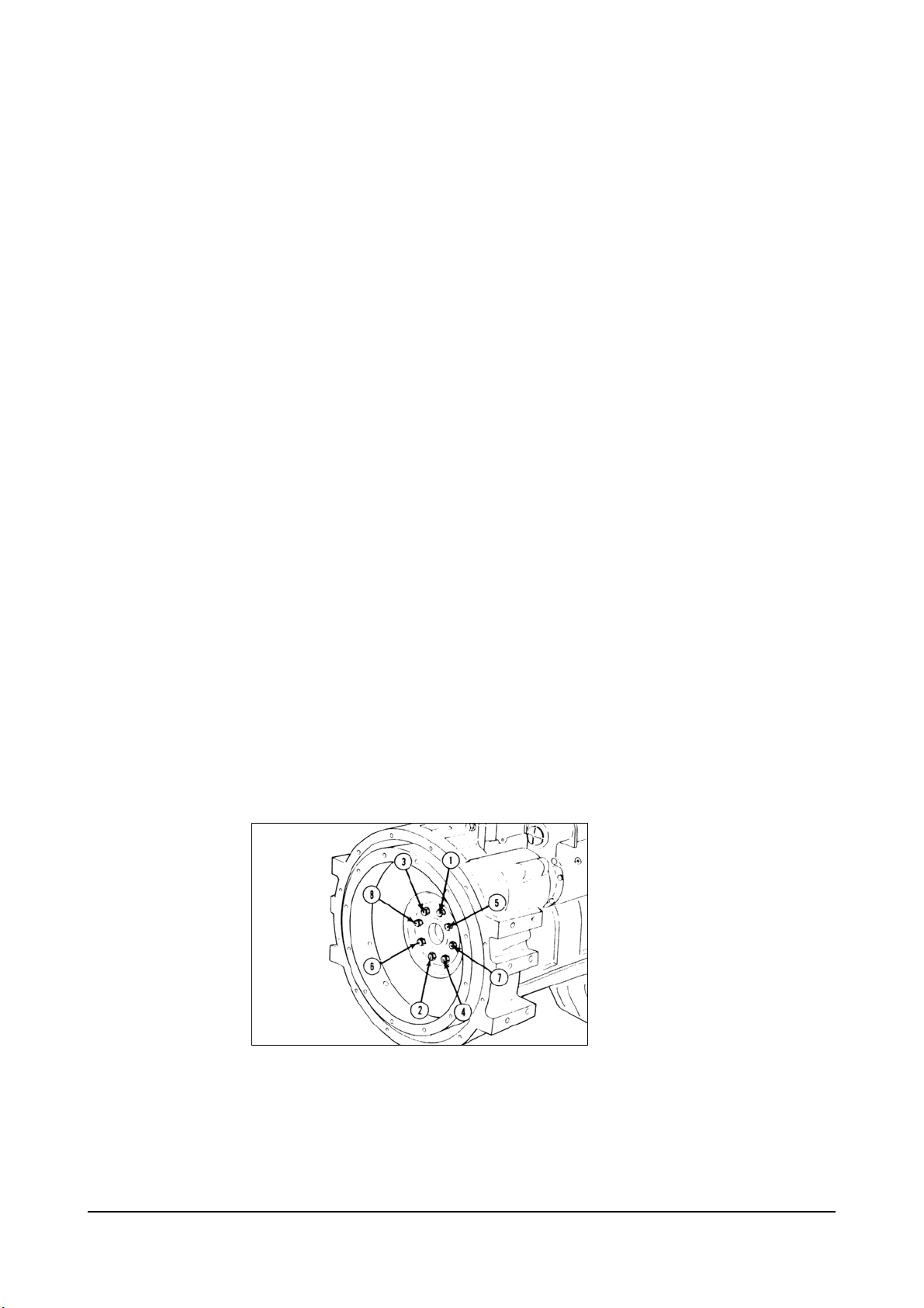
Star Pattern
Torque
Sequence
Examine a component or system for damage, excessive wear, accuracy, safety, or
performance.
Examine a component or dimension to make sure it meets the required specifications.
Check or compare the performance of a component or system to established
specifications.
Complete the necessary steps to set or adjust the component, assemblies, or system in
the required setting or position.
Look for any obvious damage or problem.
Take off a component or assembly
Remove dirt, grease or other contamination.
Take the component or assembly apart.
Restore a component or assembly to a serviceable condition within the established
specifications.
Only the easiest and simplest repairs will be made to a component or assembly. If a
component or assembly must be rebuilt; it must be replaced with a new or Cummins
Diesel Recon, Inc. replacement or be rebuilt at a Cummins authorized repair location.
Install a new, properly rebuilt, or Cummins Diesel Recon, Inc. component or assembly
in place of one which is removed.
Place a component or assembly in the correct position.
A Series Diesel Engine Introduction
7
Illustrations
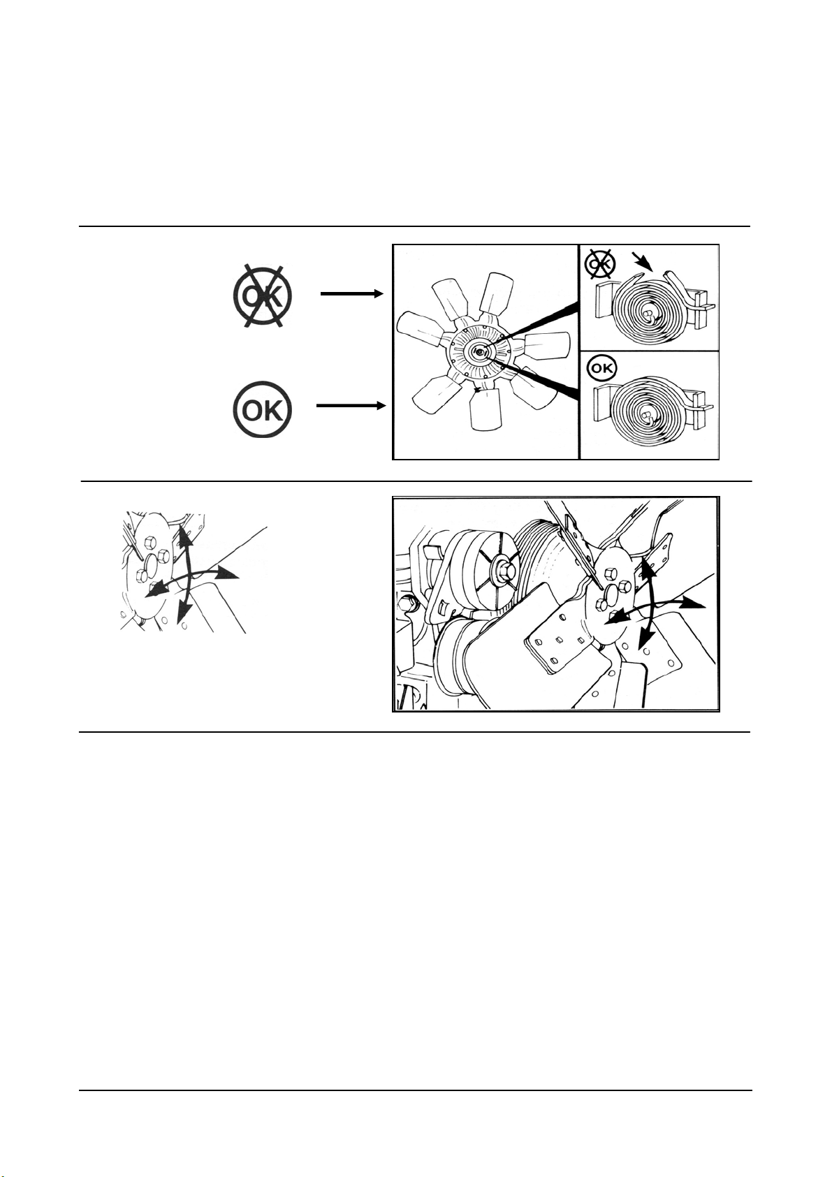
The illustrations used in the Diagnosis Sections of this manual are intended to give an example of a problem, show
what to look for and where to look for the problem.
Most of the illustrations are generic and might not look exactly like the engine or parts used in your application.
Some illustrations contain symbols to indicate an action required and an acceptable or unacceptable condition.
Unacceptable
Acceptable
Direction of Movement
(Action)
The illustrations used in the Replacement Sections are intended to show replacement procedures when the engine
is installed in a chassis. The illustration may differ from your application, but the procedure given will be the same.
A Series Diesel Engine Introduction
8
General Engine Information
External Engine Components
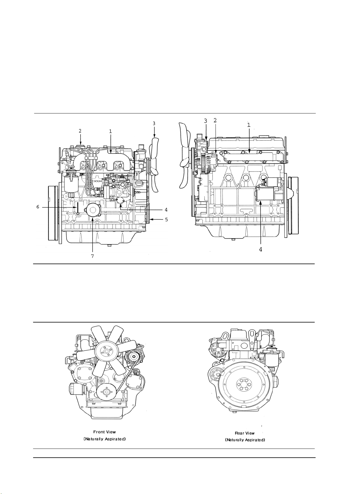
The pictures which follow show the locations of the major external engine components, the filters, and other
service and maintenance points. Some external components will be at different locations for different engine
models. Note: The pictures are only a reference to show a typical engine.
Exhaust Side [Naturally Aspirated] Intake Side [Naturally Aspirated]
1. Exhaust Manifold
2. Oil Fill Cap
3. Fan
4. Fuel Injection Pump
5. Crankshaft Pulley
6. Dip Stick
7. Oil Filter
1. Intake Manifold
2. Alternator
3. Thermostat housing
4. Starting Motor
A Series Diesel Engine General Engine Information
9
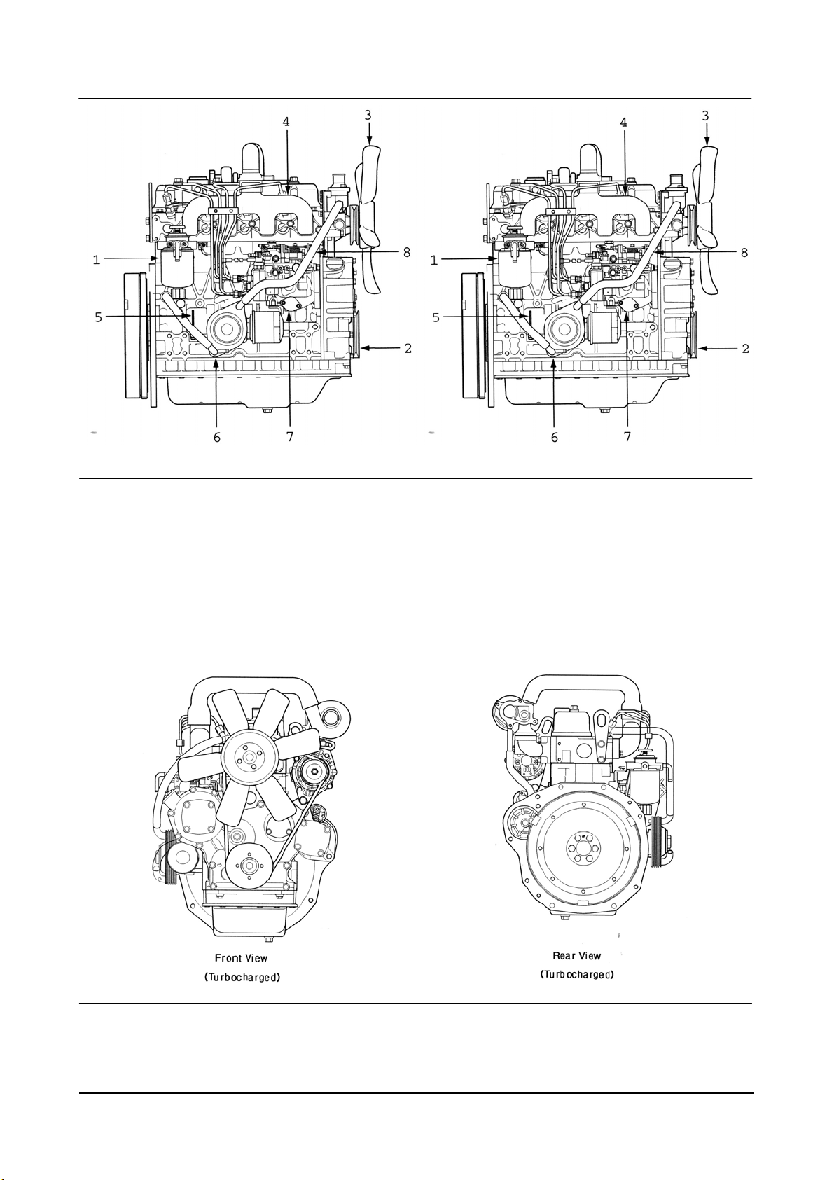
Exhaust Side [Turbocharged] Intake Side [Turbocharged]
1. Fuel Filter
2. Crankshaft Pulley
3. Cooling Fan
4. Exhaust Manifold
5. Dipstick
6. Oil Cooler
7. Fuel Injection Pump
8. Turbocharger Oil Drain Tube
1. Turbocharger
2. Alternator
3. Thermostat Housing
4. Intake Manifold
5. Starting Motor
6. Turbocharger Oil Tube
7. Oil Fill Cup
8. Air Crossover Tube
A Series Diesel Engine General Engine Information
10
Engine Specifications
Engine Model A2300
General Engine Data Naturally Aspirated
Engine Weight(Dry) Less Flywheel and Electronics 169 kg [373 lb]
Compression Ratio 21:1
Bore [mm/inch] 88 [3.46]
Stroke [mm/inch] 94 [3.7]
Displacement [ℓ/in3] 2.29 [139]
Firing Order 1-3-4-2
Valve Clearance
Rotation Viewed from the Front of the Engine Clockwise
Lubrication System Naturally Aspirated
Regulating Valve Opening Pressure 290 – 390kPa [42-56 psi]
Lubricating Oil Capacity [ℓ/gal]
Lubricating Oil Pressure at Idle(Max. Allowable) 69 kPa [10 psi]
Lubricating Oil Pressure at Rated(Min. Allowable) 245 kPa [35 psi]
Oil Filter Differential Pressure to Open Bypass Valve 98 kPa [14 psi]
Number of liters [qt] from Low to High 2.0 ℓ [0.53 gal]
Lubrication System Forced Lubrication with Pump
Intake 0.3 mm [0.012 in]
Exhaust 0.3 mm [0.012 in]
Total System 7.0 [1.85]
Standard Oil Pan
Only
6.5 [1.72]
Cooling System Naturally Aspirated
Coolant Capacity (Engine Only) [ℓ/gal] 3.0 [0.7]
Start 71 [160] Standard Modulating Thermostat
Range
[℃/F]
Cooling System Forced Lubrication with Pump
Air Induction System Naturally Aspirated
Maximum Allowable Intake Restriction at Rated Speed and
Load with Dirty Filter Element
Exhaust System Naturally Aspirated
Maximum Allowable Exhaust Restriction at Rated Speed
and Load with Dirty Filter Element
Fuel System Naturally Aspirated
Injection Pressure 150 kPa [22 psi]
Starting System
A Series Diesel Engine General Engine Information
Pulley Open 8 [185]
6.23 kPa [635 mmAq]
5.88 kPa [600 mmAq]
Electric starting with Starter Motor
(12 V –2.0 kW)
11

Troubleshooting Logic
Engine Diagrams
A schematic of each of the major engine systems is provided at the beginning of the section of the manual devoted
to troubleshooting and repairing that particular system.
The diagrams depict flow through the various engine systems. The information and configuration of the
components illustrated in the drawings are of a general nature. Some items for specific applications and
installations may be different.
Each Section also contains a discussion regarding diagnosing malfunctions for that specific system.
Knowledge of the systems can help you troubleshoot and repair the engine.
Problem Isolation and Correction
The following Troubleshooting Logic is designed to help you organize your study of a problem and to plan a
procedure to correct it. The series of fault/logic charts given do not provide all the answers, but they should
stimulate a train of thought that will lead you to the source of the trouble.
Be sure to consider any maintenance or repair action that could have caused the problem.
If the engine surges or runs rough initially after not being used for 2 months or more, do not assume that the
engine has a malfunction. Varnish can form on the internal parts of the injection pump and the oil film can drain
from the piston rings. Operate the engine for at least 5 minutes before troubleshooting.
The basic procedure is as follows:
z Study the problem thoroughly.
z Relate the symptoms to your knowledge of the engine components and systems.
z Double-check before beginning the disassembly.
z Solve the problem by deduction starting with the easiest things.
z Determine the cause of the problem and make a thorough repair.
z After making corrections, operate the engine in normal conditions to verify the cause of the problem was
corrected.
A Series Diesel Engine Troubleshooting Logic 12
Troubleshooting Logic
Page List of Symptoms
52 Alternator Not Charging or Insufficient Charging
36 Coolant Loss
32 Coolant Temperature Above Normal
35 Coolant Temperature Below Normal
46 Compression Knocks
43 Contaminated Coolant
44 Contaminated Lube Oil
15 Engine Cranks But Will Not Start – No Smoke From Exhaust
16 Engine Hard to Start Or Will Not Start – Smoke From Exhaust
24 Engine RPM Will Not Reach Rated Speed
22 Engine Runs Rough or Misfiring
18 Engine Starts But Will Not Keep Running
14 Engine Will Not Crank Or Cranks Slowly
48 Engine Will Not Shut Off
51 Excessive Engine Noises
30 Excessive Engine Smoke
47 Excessive Fuel Consumption
49 Excessive Vibration
45 Fuel or Oil Leaking From Exhaust Manifold
26 Low Power
41 Lube Oil Loss
38 Lubricating Oil Pressure Low
40 Lubricating Oil Pressure Too High
20 Rough Idle (Irregularly Firing Or Engine Shaking)
19 Surging (Engine Speed Change)
A Series Diesel Engine Troubleshooting Logic 13
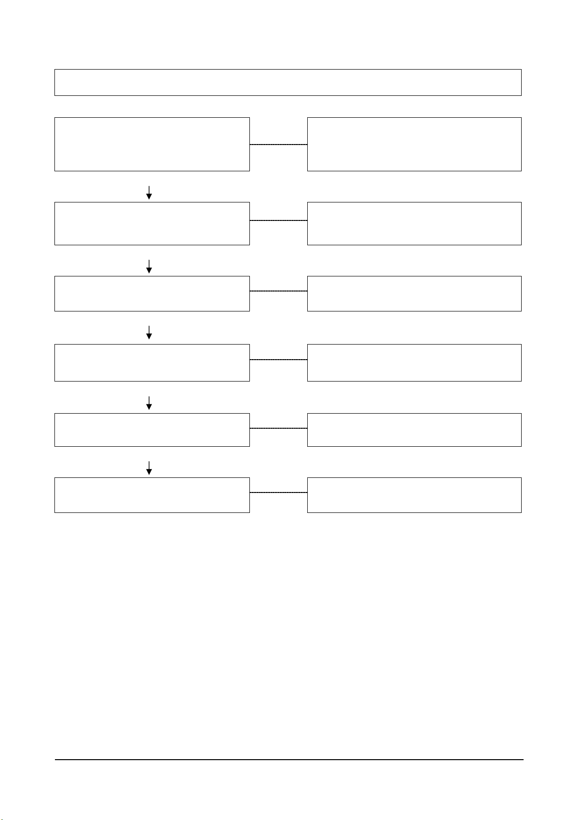
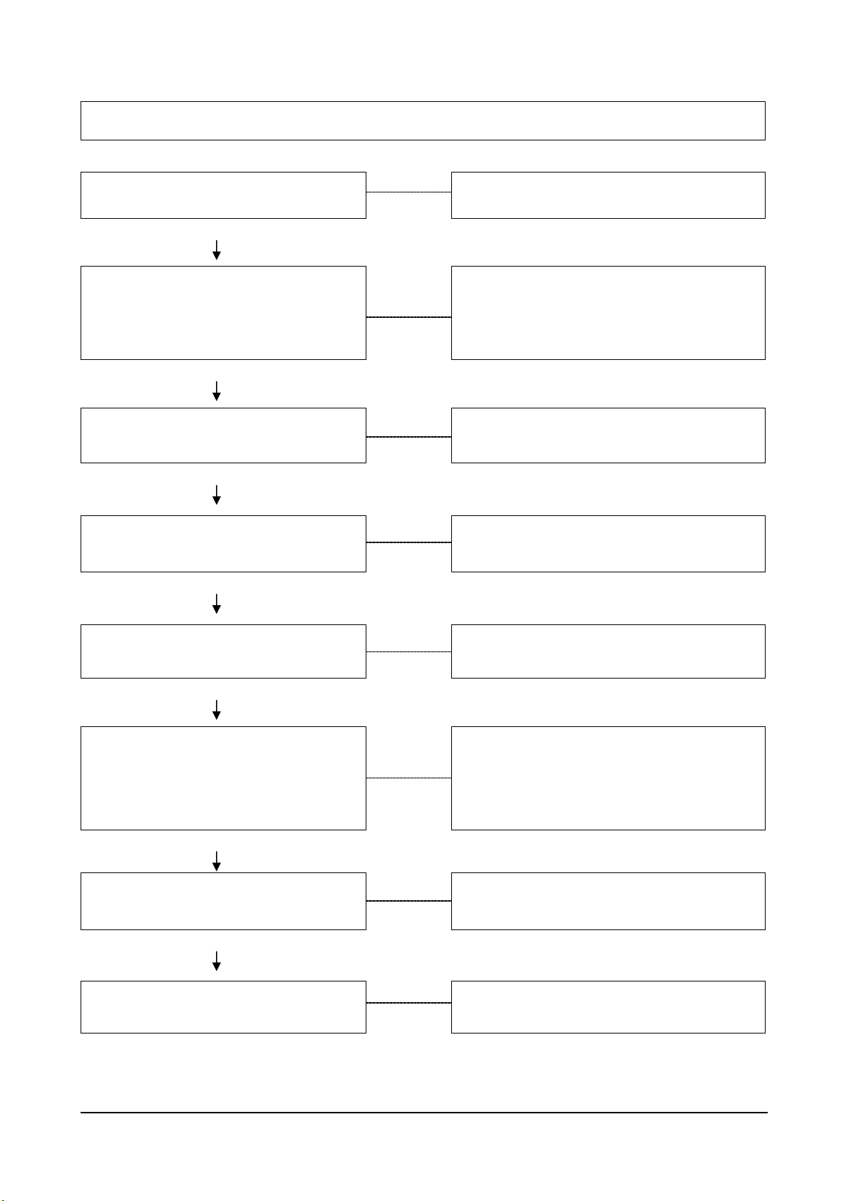
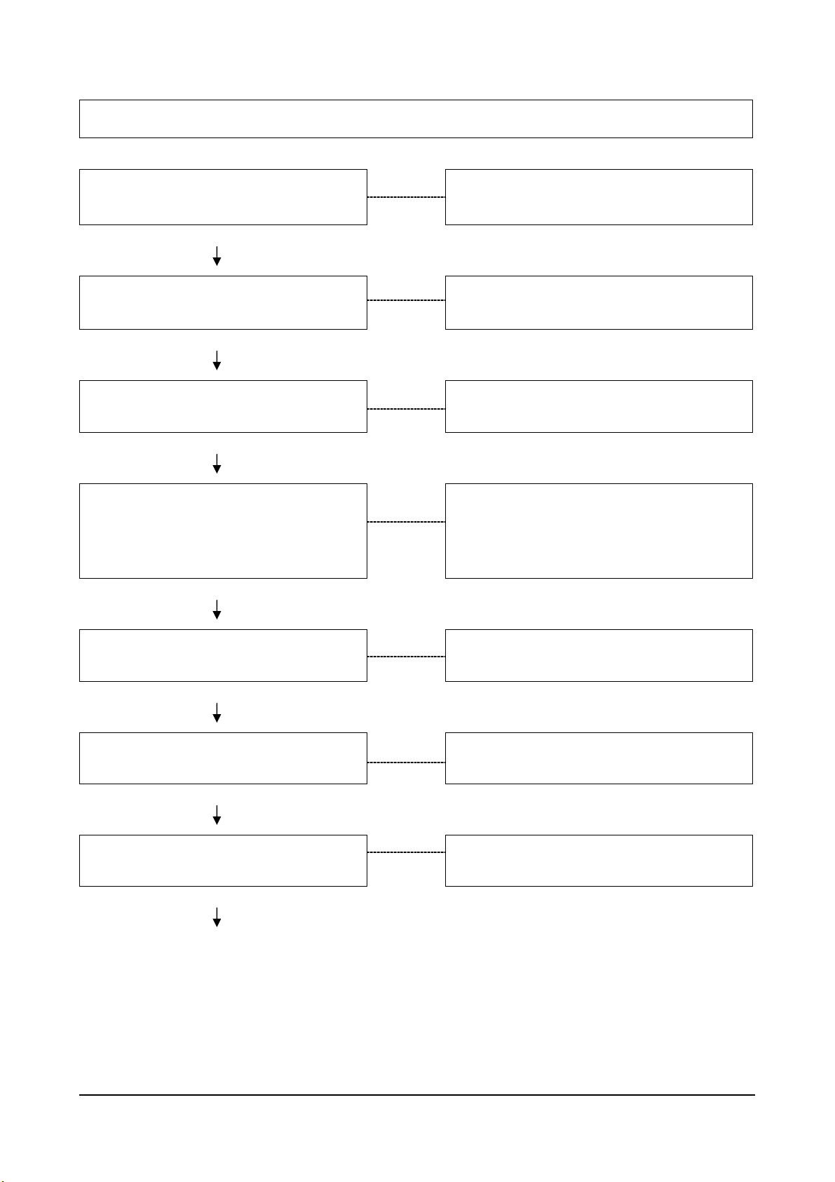
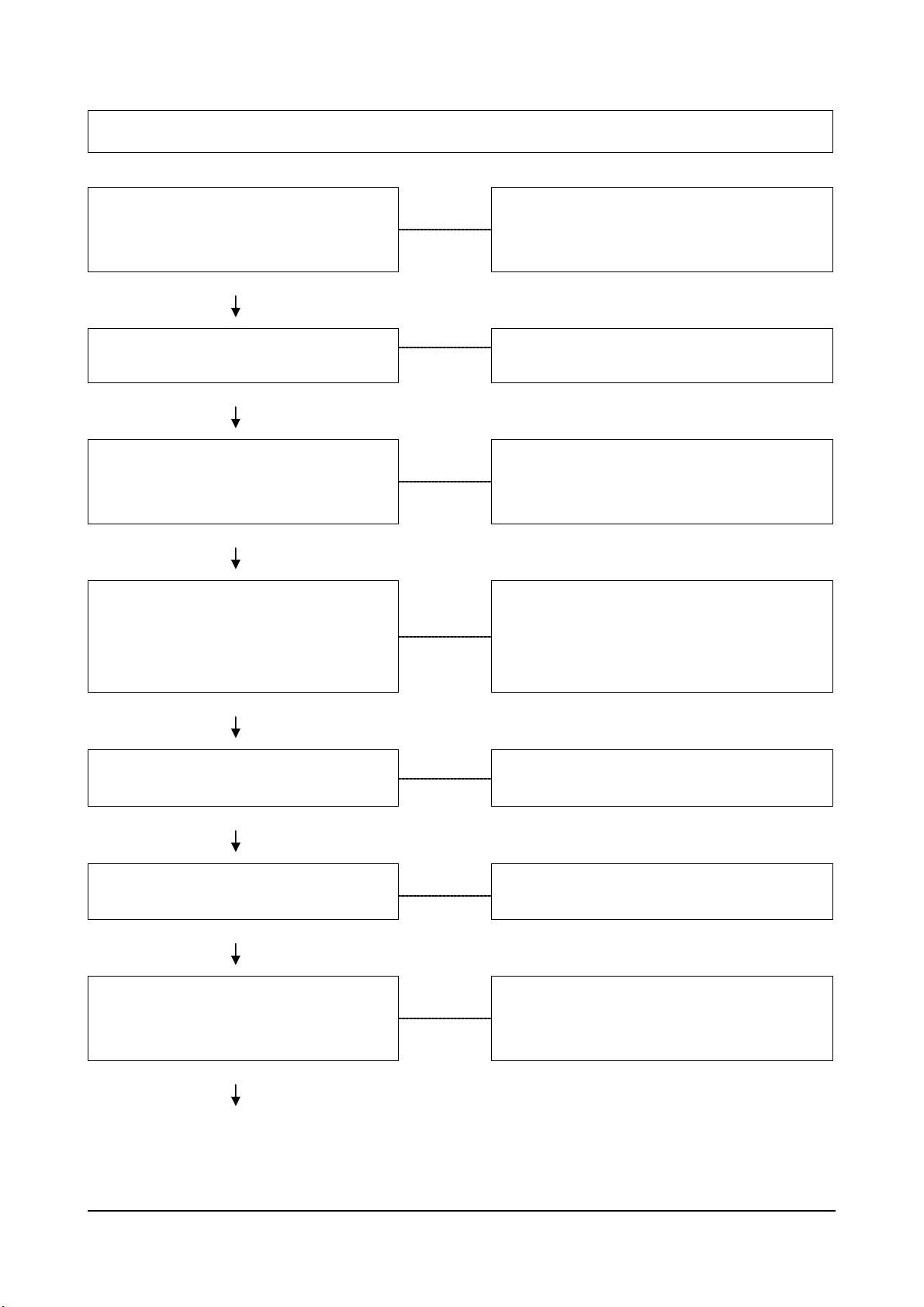
Engine Will Not Crank or Cranks Slowly
Cause Correction
Starting Motor Operating But Not
Cranking the Engine
OK
Crankshaft Rotation Restricted
OK
Starting Circuit Connections Loose
Or Corroded
OK
Battery Charge Low
OK
Remove the Starting Motor and Check for
Broken Teeth on the Flywheel or Broken
Starting Motor Spring. Refer to Page 138
Bar the Engine to Check for Rotational
Resistance. Refer to Page 138
Clean and Tighten Connections.
Refer to Page 137
Check Battery Voltage.
Refer to Page 137
No Voltage to Starter Solenoid
OK
Solenoid or Starting Motor
Malfunction
Check Voltage to Solenoid.
Refer to Page 137
Replace Starting Motor.
Refer to Page 144
A Series Diesel Engine Troubleshooting Logic 14
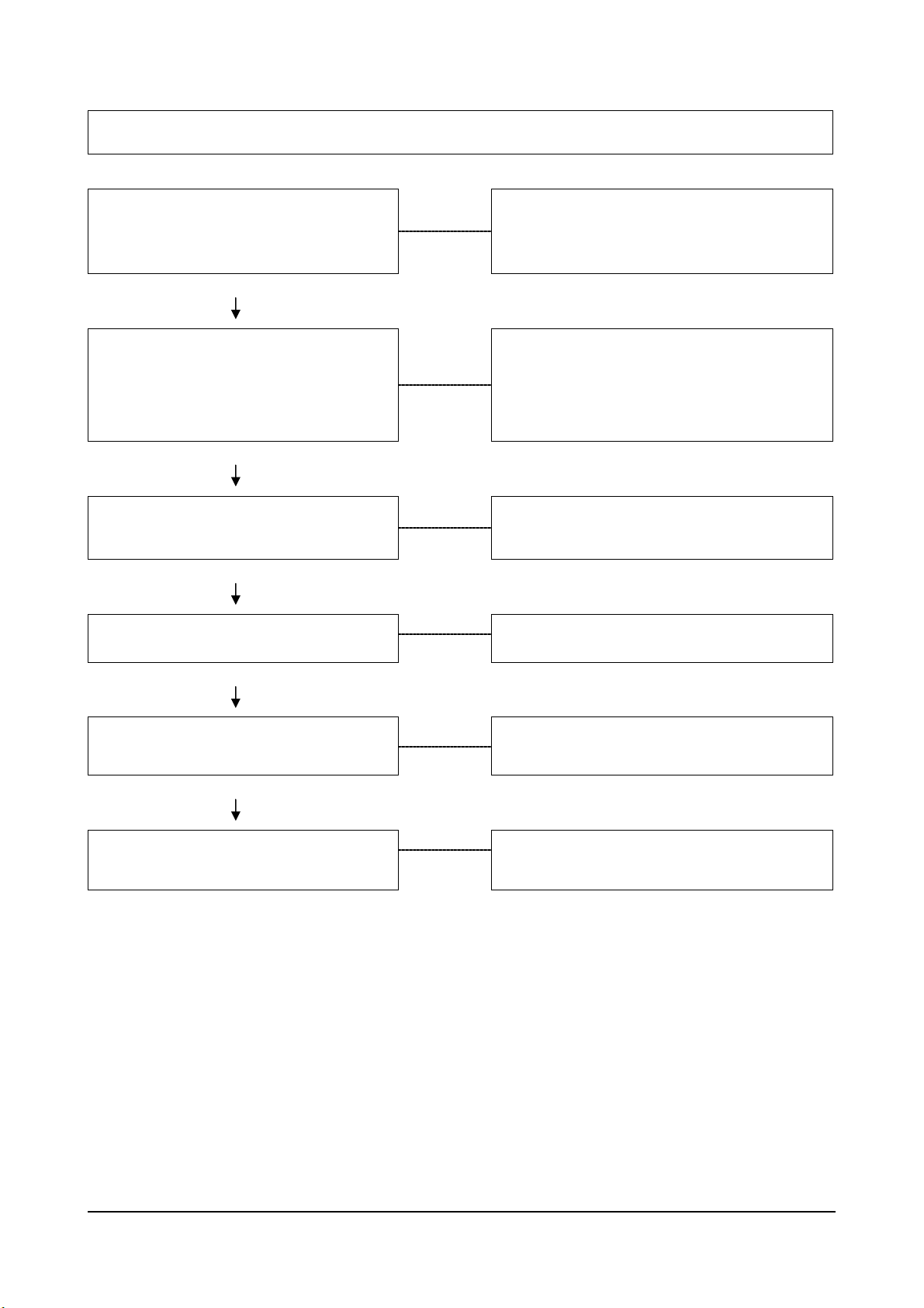
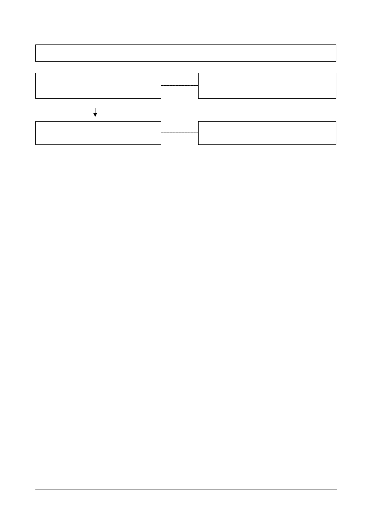
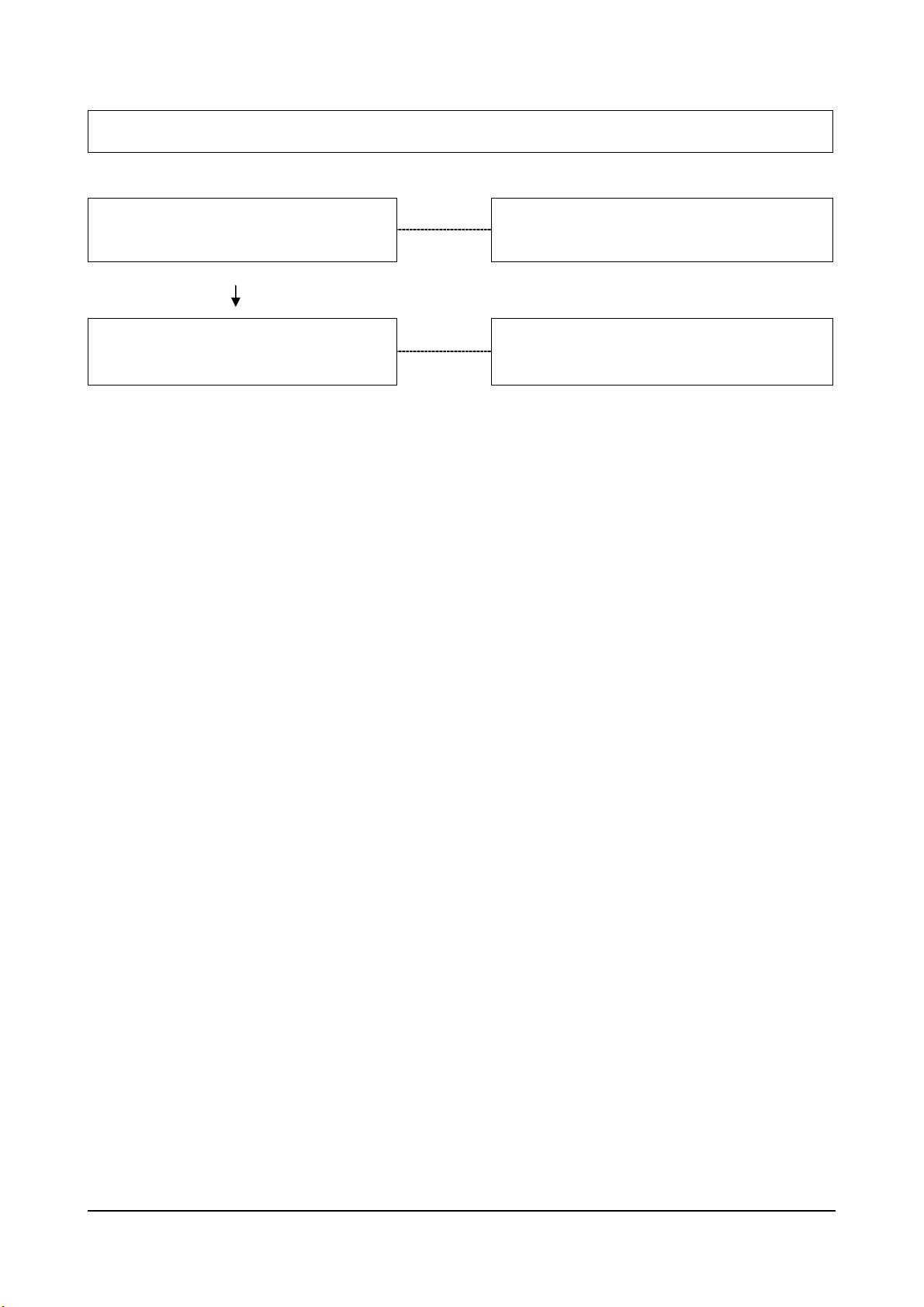
Engine Cranks But Not Start – No Smoke From Exhaust
Cause
No Fuel in Supply Tank
OK
Electrical or Manual Fuel
Shutdown Not Open
OK
Air Intake or Exhaust Plugged
OK
Fuel Filter Plugged With Water or
Other Contamination
OK
Check/Replenish Fuel Supply
Check for Loose Wires and Verify that the
Valve is Functioning. Check to be sure
Manual Shut Off Lever is in the Run
Position. Refer to Page 74
Visually Check: Remove the Obstruction.
Drain Fuel/Water Separator or Replace
Fuel Filter. Refer to Page 71, 83
Correction
Injection Pump Not Getting Fuel or
Fuel is Aerated
OK
Worn or Malfunctioning Injection
Pump
OK
Internal Pump Timing Incorrect
OK
Camshaft Out of Time
Check Fuel Flow/Bleed Fuel System.
Refer to Page 83
Visually Check Fuel Delivery with an
Externally Connected Injector to One of
the Pump Outlets. Replace the Pump if
Fuel is Not Being Delivered. Refer to Page
94
Verify/Time the Pump.
Refer to Page 77
Check/Correct Gear Train Timing
Alignment. Refer to Page 77, 185
A Series Diesel Engine Troubleshooting Logic 15

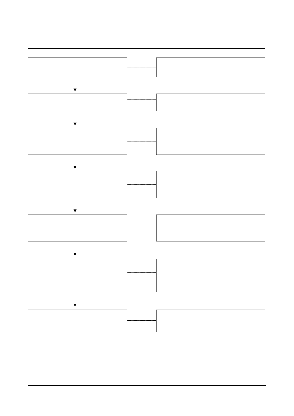
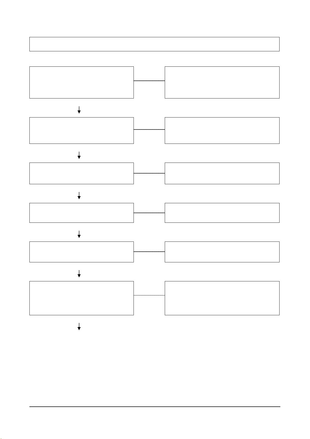
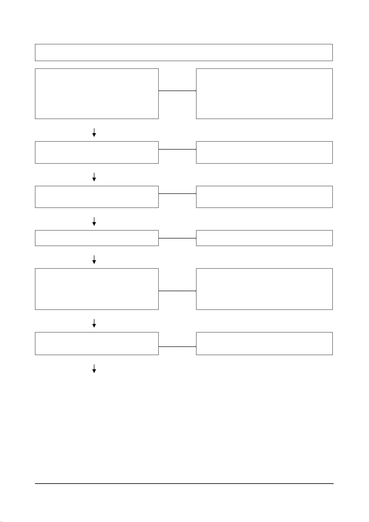
Engine Hard To Start Or Will Not Start – Smoke From Exhaust
Cause
Incorrect Starting Procedure
OK
Cranking Speed Too Slow
OK
The Fuel Control Lever on the Bosch VE
Pump Must be Moved to One-Half Travel.
The Fuel Shut Off Control Must Be in the
Run Position. Refer to O&M Manual.
Verify that the Driven Units are not
Engaged.
Check the Battery, Starting Motor, and
Look for Loose or Corroded Wiring
Connections. Refer to Page 137
Bar the Engine to Check for Internal
Rotational Resistance.
Correction
Cold Starting Aids Not Working or
Are Needed
OK
Insufficient Intake Air
OK
Air in the Fuel System or the Fuel
Supply is Inadequate
OK
(Continued)
Verify the Aids are Operating. Refer
To O&M Manual.
Inspect or Replace Filter and Check for
Obstructions to the Air Supply Tube.
Refer to Page 98, 112
Check the Flow through the Filter and
Bleed the System. Locate and Correct the
Air Source. Refer to Page 83
A Series Diesel Engine Troubleshooting Logic 16
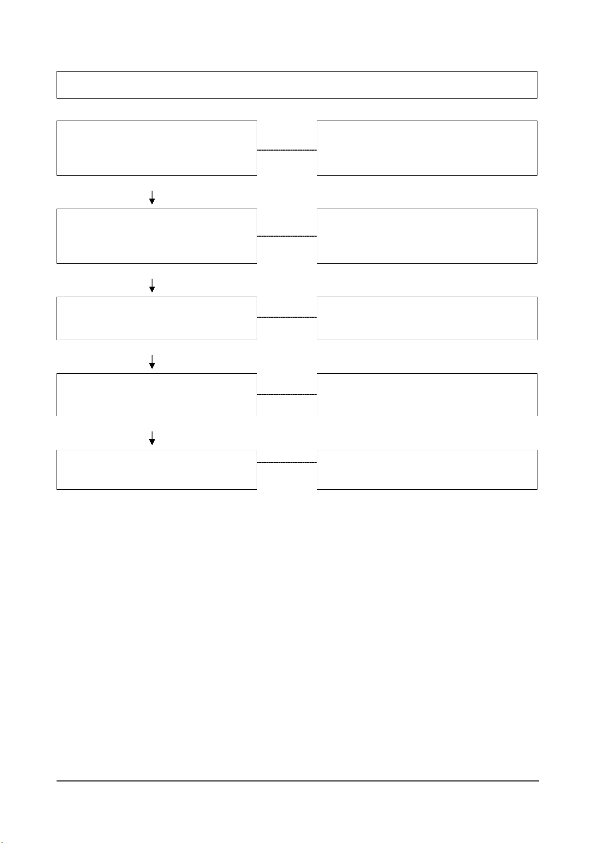
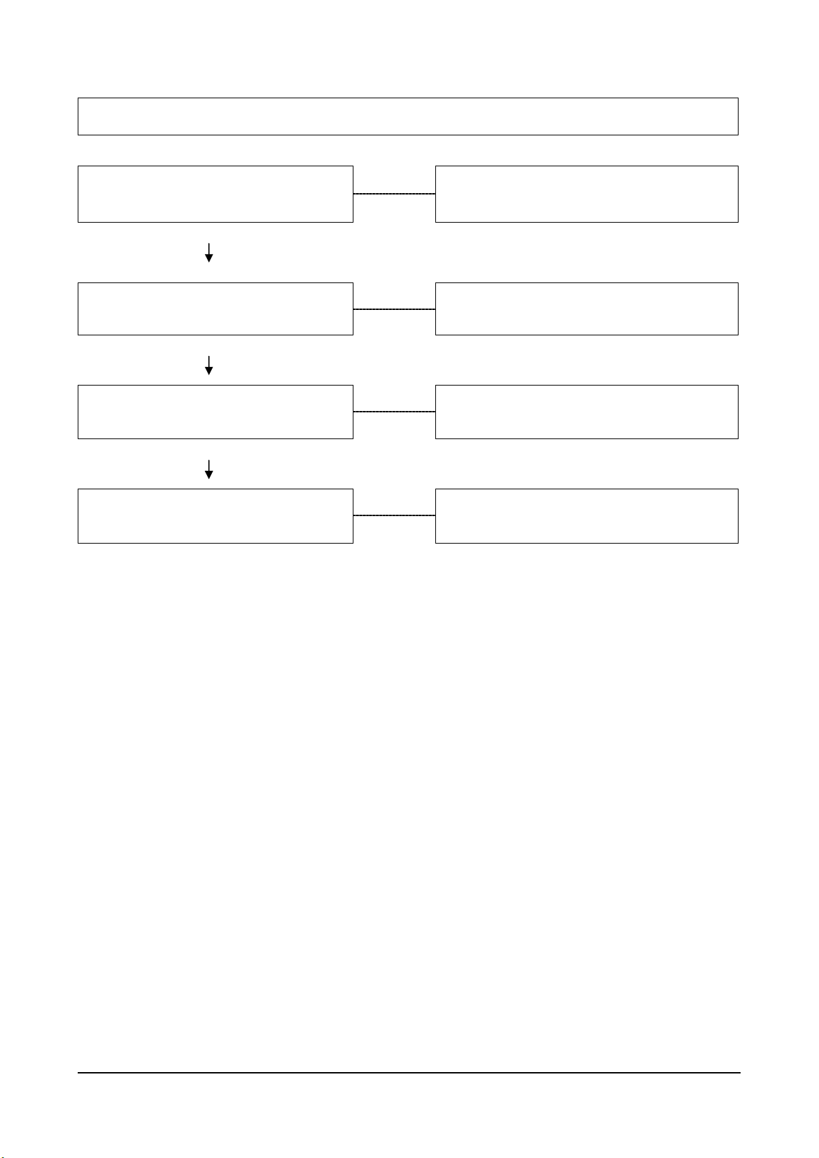
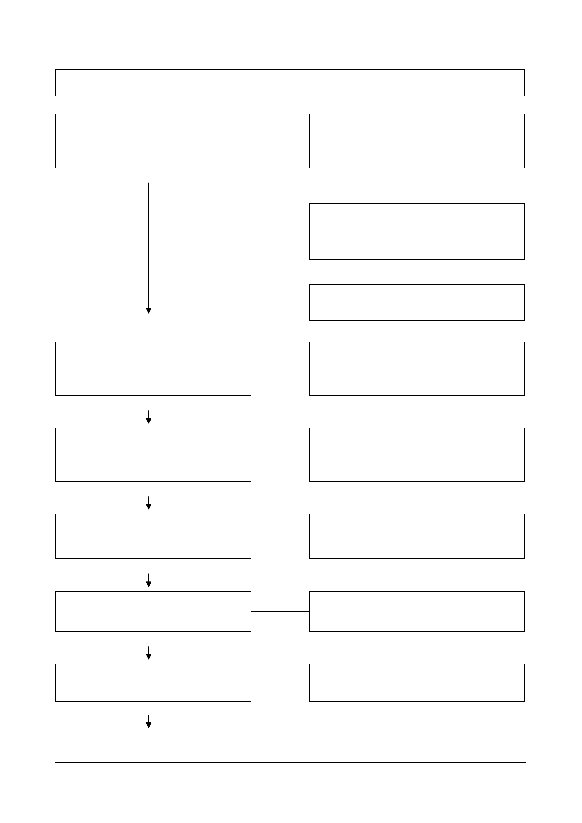
Engine Hard To Start Or Will Not Start – Smoke From Exhaust (Continued)
Cause Correction
Contaminated Fuel
OK
Worn or Malfunctioning Injection
Pump
OK
Injection Pump Out of Time
OK
Valves Incorrectly Adjusted
OK
One or More Injectors Worn or
Malfunctioning
OK
Engine Compression Low
Verify by Operating the Engine with Clean
Fuel from a Temporary Tank. Drain and
Flush Fuel Supply Tanks.
Visually Check Fuel Delivery With an
Externally Connected Injector to one of the
Pump Outlets. Replace the Pump if Fuel is
Not Being Delivered. Refer to 94
Check/Time the Pump.
Refer to Page 77, 96
Adjust Valves. Refer to Page 179
Check/Replace Injectors.
Refer to Page 88
Perform a Compression Check to Identify
the Problem. Refer to Page 158
A Series Diesel Engine Troubleshooting Logic 17
Engine Starts But Will Not Keep Running
Cause
Engine Starting Under Load
OK
Idle Speed Too Low For
Accessories
OK
Intake Air or Exhaust System
Restricted
OK
Air in the Fuel System or the Fuel
Supply is Inadequate
Disengage Driven Units.
Adjust the Idle Speed.
Refer to Page 73
Visually Check for Exhaust Restriction and
Inspect the Air Intake.
Refer to Page 99, 101
Check the Flow Through the Filter and
Bleed the System. Locate and Correct the
Air Source. Refer to Page 83
Correction
OK
Fuel Waxing Due to Extremely Cold
Weather
OK
Contaminated Fuel
OK
Restricted Fuel Drain Manifold or
Return Line
Verify by Inspecting the Fuel Filter.
Clean the System and Use Climatized
Fuel or Fuel Heaters.
Verify by Operating the Engine With Clean
Fuel from a Temporary Supply Tank. Drain
and Flush the Fuel Supply Tank.
Check/Correct the Restriction.
Refer to Page 81
A Series Diesel Engine Troubleshooting Logic 18
Surging (Speed Change)
Cause
If the Condition Occurs at Idle, the
Idle Speed is Set Too Low for
Accessories
OK
High Pressure Fuel Leak
OK
One or More Injectors Worn or
Malfunctioning
OK
Malfunctioning Delivery Valve
Adjust the Idle. Refer to Page 73
Inspect/Correct Leaks in the Pressure
Lines. Fittings, Injector Sealing Washers
or Delivery valves. Refer to Page 78
Check/Replace the Injectors.
Refer to Page 88
Replace Delivery Valves.
Refer to Page 84
Correction
OK
Malfunctioning Injection Pump
Replace the Pump.
Refer to Page 94
A Series Diesel Engine Troubleshooting Logic 19
Rough Idle (Irregularly Firing Or Engine Shaking)
Cause Correction
Cold Engine
OK
Idle Speed Too Low for the
Accessories
OK
Engine Mounts Over-Tightened,
Damaged or Loose
OK
High Pressure Fuel Leak
OK
Air in the Fuel System
OK
Sticking Needle Valve in an Injector
OK
Malfunctioning Delivery Valve
Refer to Troubleshooting Logic for Engine
Running Too Cold. Refer to 35
Check/Adjust Low Idle Screw.
Refer to Page 73
Verify Condition of Mounts. Refer to
Equip. Manufactures Service Instructions.
Inspect/Correct Leaks in the High
Pressure Lines, Fittings Injection Sealing
Washers or Delivery Valve Seals. Refer to
Page 78
Bleed the Fuel System and Correct the
Source of the Air. Refer to Page 83
Replace the Injector.
Refer to Page 88
Replace Delivery Valves.
Refer to Page 92
OK
(Continued)
A Series Diesel Engine Troubleshooting Logic 20
Rough Idle (Irregularly Firing Or Engine Shaking)(Continued)
Cause
Valves Not Sealing
OK
One or More Cylinders Losing
Compression
Adjust Valves. Refer to Page 179
Perform a Compression Check and Repair
as Required. Refer to Page 160
Correction
A Series Diesel Engine Troubleshooting Logic 21
Engine Runs Rough Or Misfiring
Cause Correction
Fuel Injection Lines Leaking
OK
Air in the Fuel or the Fuel Supply is
Inadequate
OK
Contaminated Fuel
OK
Incorrect Valve Adjustment
OK
Injection Pump Timing Incorrect
OK
Inspect/Correct Leaks in the High
Pressure Lines, Fittings Injector Sealing
Washers, or Delivery Valve. Refer to Page
78
Check the Flow Through the Filter and
Bleed the System. Locate and Correct the
Air Source. Refer to Page 83
Verify by Operating the Engine with Clean
Fuel from a Temporary Tank.
Check for a Bent Push Rod and Adjust
Valves. Refer to Page 179
Check/Time Pump.
Refer to Page 77
One or More Cylinders Has Low
Compression
OK
(Continued)
A Series Diesel Engine Troubleshooting Logic 22
Perform a Compression Check to Isolate
the Cause of Low Compression (Piston
Rings, Head Gasket or Valves). Refer to
Page 158
Engine Runs Rough Or Misfiring (Continued)
Cause Correction
Malfunctioning Injectors
OK
Defective Injection Pump
(Delivery Valves)
OK
Camshaft Out of Time
OK
Damaged Camshaft or Tappets
Replace Injectors.
Refer to Page 88
Replace Injection Pump.
Refer to Page 94
Check/Correct Gear Train Timing
Alignment. Refer to Page 185
Inspect Camshaft.
Refer to Page 182
A Series Diesel Engine Troubleshooting Logic 23
Engine RPM will Not Reach Rated Speed
Cause Correction
Engine Overloaded
OK
Malfunctioning Tachometer
OK
Throttle Linkage Worn or
Incorrectly Adjusted
OK
If the Problem Occurs After
Replacing the Fuel Control Lever
or Pump, Incorrectly Indexed Lever
(Robert Bosch VE Only)
Verify High Idle Speed Without Load.
Investigate Operation to be Sure Correct
Gear is Being Used.
Verify Engine Speed with Hand
Tachometer - Correct as Required.
Adjust Linkage for Stop-to-Stop Fuel
Control Lever Travel.
Refer to Page 73, 225
Check/Correct Fuel Control Lever
Indexing.
Refer to Page 74
OK
High Speed Stop Screw Incorrectly
Adjusted
OK
Partially Engaged Mechanical
Shutdown Lever
OK
Inadequate Fuel Supply
OK
(Continued)
Check/Set High Speed Stop Screw.
Refer to Page 74, 225
Check/Place Shutdown Lever in Run
Position. Refer to Page 74, 225
Check the Flow Through and Filter to
Locate the Source of the Restriction.
Refer to Page 68
A Series Diesel Engine Troubleshooting Logic 24
Engine RPM will Not Reach Rated Speed (Continued)
Cause Correction
If the Condition is Intermittent,
Restricted Manifold Drain Line
OK
Malfunctioning Injection Pump
Check/Remove Restriction.
Refer to Page 81
Replace Pump.
Refer to Page 94
A Series Diesel Engine Troubleshooting Logic 25
Low Power
Cause Correction
If the Condition is Slow Throttle
Response, Leaking Air Fuel
Control Tube or Malfunction
Control in the Pump
(Automotive Only)
OK
Fuel Control Lever Not Moving to
Full Speed.
OK
Mechanical/Shutdown Lever
Partially Engaged
OK
High Oil Level
OK
Tighten the Fittings. Replace the Pump if
the Controls are Not Functioning.
Refer to Page 87
Check/Correct for Stop-to-Stop Travel.
Refer to Page 73, 225
Check/Replace Shutdown Lever in Run
Position. Refer to Page 74, 225
Check/Correct Oil Level
Engine Overloaded
OK
Incorrect External Injection Pump
Timing
OK
(Continued)
Check for Added Loading from
Malfunctioning Accessories or Driven
Units, Brakes Dragging and Other
Changes in Vehicle Loading
Verify Pump Timing Marks are Aligned.
Refer to Page 77, 96
A Series Diesel Engine Troubleshooting Logic 26
Low Power (Continued)
Cause
Inadequate, or High or Low
Temperature Intake Air
OK
High Pressure Fuel Leak
OK
Inspect/Replace Air Cleaner Element.
Look for Other Restrictions.
Refer to Page 112
If the vehicle is equipped with a Valve to
Switch the Intake Source from Under the
Hood to Outside, Position the Valve for the
Season.
Coolant Passage in the After Cooler
Plugged.
Inspect/Correct Leaks in the High
Pressure Lines, Fittings Injector Sealing
Washers or Delivery Valve Seals. Refer to
Page 78
Correction
Inadequate Fuel Supply
OK
High Fuel Temperature
OK
If Low Power is Intermittent,
Restricted Fuel Drain Manifold
OK
Poor Quality Fuel
OK
(Continued)
Check the Flow Through the Filter to
Locate the Source of the Restriction.
Refer to Page 68
Check for a Restricted Fuel Drain Manifold
(Robert Bosch VE)
Check/Correct Restriction.
Refer to Page 81
Verify by Operating From a Temporary
Tank With Good Fuel.
A Series Diesel Engine Troubleshooting Logic 27
Low Power (Continued)
Cause Correction
Air Leak Between the
Turbocharger and the Intake
Manifold.
OK
Exhaust Leak at the Manifold or
Turbocharger
OK
Malfunctioning Turbocharger
OK
Valve Clearances Incorrect
OK
Injection Pump Internal
Malfunctioning
Check/Correct Leaks in the Air Crossover
Tube, Hoses, or Through Holes in the
Manifold Cover. Refer to Page 100, 101
Check/Correct Leaks in the Manifold or
Turbocharger Gaskets. Look for a cracked
Manifold. Refer to Page 101
Inspect/Replace Turbocharger.
Refer to Page 101, 105, 109
Check/Adjust Valves. Refer to Page 179
Check/Time Pump. Refer to Page 77
OK
Low Engine Compression
OK
Worn or Malfunctioning Injectors
OK
(Continued)
Perform Compression Check to Identify
Malfunction. Correct as Required.
Refer to Page 158
Check Injectors. Refer to Page 79
A Series Diesel Engine Troubleshooting Logic 28
 Loading...