

Page 1
-.B)pzGGq
Diagnostic Service Manuals
SERVICE
United States
SALES OFFICES
DOMETIC SALES CORP.
Zone 1
2320 Industrial Parkway
Elkhart. IN 46515
(219)
295.5226
DOMETIC
SALE S
Zone II
2920 Avenue
Arlington, TX 76011
(81 7)
649.5726
DOMETIC
Zone III
14441 Bonelli St.
City of Industry, CA 91746
(818 ) 968-9431
Canada
CORP .
“E”
East
SALES CORP.
DOMETIC DISTRIBUTION INC
866 Langs Drive
CambrIdge. Ontario
N3H
2N7
Canada
(519 ) 653-4390
SERVICE MANUAL
c
REFRIGERATOR
for
recreat ional vehicles
RM24A RM36C
RM46 RM4
7
Edition
Publication No
4528-E/Service
May
DSC #
1
1973
648
When
orderi ng
MODEL. QUANTITY. PART NUMBER. DESCRIPTION
For
electric details
VOLTAGE. WATTAGE
SPARE PARTS
also:
always
state:
RM66 RM67
1
RM76 RM77
1
Page 2
2
Service Instructions for Domtic Absorption Refrigerators
The absorption refrigerators described in this manual are
in recreational vehicles.
Since the vehicles in
camp sites
designed co operate by means of bottle propane or butane gas as
electricity
These Service Instructions cover the Dometic
RM46,
Description
ECHNIGU
Cabinet es,
INSTALLATION
General
Ventilation___
Gas connections ____ ____
Electrical connections___________..______ 5
Approved installations
Measurements...
FEATURES
equipment .
INSTRUCTIONS
instructions . ____ .
....
where
12/110V.
RM47, RM66, RM67,
.._ .... ..... ......... .....
...................
........... ....
____
............ ........
which
electrical power is not available,
..........
the refrigerators are
RM76,
RM77.
LIST OF CONTENTS
Pag
3
10
primarily
located
may be driven to remote
the refrigerator5 have been
Models RM24, RM36C,
Description
ELECTRIC OPERATION -
Re place ment
Wiring diagrams................................
4
5
5
7
PRESSURE
OPERATING RECOMMENDATIONS
Gas operation
Electric
MAINTENANCE
Levelling
of heater_______________.__.
MEASURING
_______ _____ _______ _____
operation
_________
for installation
well as
by
FUNCTIONAL
DEVICES
.................
..................
PARTS
........ .......
Page
37
38
39
40
41
42
Cabinet
THE
GAS/ELECTRIC EQUIPMENT
AS
Adjustments
To change the door panel _ . _ ____ _____
Replacement of door gasket___.________.. 15
Replacement of evaporator door and gasket. 16
Reversing outer door__
ABSORPTION REFRIGRATOR SYSTEM
Sealed system constructions .. _ _ _ _ .
Operating analysis for cooling unit ......
Cooling unit replacement
Gas
equipment for
Dual electric equipment for
Car/electric
RM46,
RM47,
OPERATION Termostat -
The gas burner ...... .
Flue system .......................
Thermo flame
equipment
RM66, RM67, RM76,
FUNCTIONAL
replacment
failure device ........ .......
.... . ...... ......
.............. ...
RM24
..... . .....
RM24 . .......
for
RM36C,
RM77... ____
PARTS
___
......
.
..... ..
.............. ..........
....
___
......
........
32
.........
20
22
23
29
30
33
34
13
18
28
35
Temperature Control (thermostat).... 42
The
themostat capillary
Storing food in the refrigerator_______.
Cleaning _____
Ice cubes___________ ____ ______________
Travel latch ____ ____ _____
Door seal_
Odors inside the refrigerator
Odors from
Flame blows out
Flint lighter_______
Piezo
lighter ____________ _ ____ _________
DIAGNOSIS
Trouble
refrigerators _____ __
Trouble
refrigerators_______ .... .
Failed refrigerating unit_____..._____._
Operation analysis for electric
operated
shooting - electric operated
.... .
......
___ ______ ______ ____ ___
fumes .......... .......
..... ........ .
shooting -
refrigerators
tube
..........
______
gas
......... ......
.............. .
....... .....
____ ________
...... ........ ....
...... .............
operated
. ......... ......
............. .......
42
43
43
43
43
43
44
44
44
44
45
47
48
49
50
Operation
operated
Periodic
analysis for LP gas
refrigerators
maintenance
....... ...........
................ ..
51
52
Page 3
1..
TECHNICAL FEATURES
RM24
3
The cabinet has a so called “Full Finish Casing”
built-in. RM24 is a compact refrigerator, ideal for campers, fitted with
and seals.
This refrigerator is fitted with right-hand door with change over facility to
hand door and exchangeable front door panel in an aluminium framed door.
Exchange can be made without the removal of the door.
available operated from the rear of the cabinet.
fitted as standard to assist in maintaining flame stability under adverse wind
conditions.A sealing frame is fitted around the cabinet for building-in purposes,
The refrigerator has one basic casing which is Foamed in place with a lining.
Insulation material polyurethane.
The construction of the door,
foamed in place with the door pan and magnetic gasket.
Equipment
Fool-proof electric/gas interlock system.
Flint lighting system. The electric and the gas thermostats are of the English
complete, is an aluminium extruded door frame
Thermo-electric flame failure device.
and can be used freestanding or
front
frame
left-
A full range of equipment is
A blow-out protection flue is
Ranco-make .
The
gas/e1
through the service door in the wall, when installed in a
controls are located at the rear of the refrigerator and are acccssiole
vehicle.
Version
Gas/110
RM36C, RM46, RM47, RM66,
Cabinet
Thin wall polyurethane insulation.
place insulation.
Lining of vacuum-foamed
moulded SB plastic.
Distinct stop for evaporator door at
Cabinet shelf with hinge for big bottles,
The shelves run in grooves and will not move during transport of the vehicle.
Freezer compartments are, of aluminiurn sheet,except
moulded part of the lining.
Accessible control panel inside the fresh food compartment.
volts A.C. and 12 volts D.C.
RM67, RM76, RI.177
RM76
and RM77 are foamed against mould.
ABS
plastic, except
All models except
RM36C,
90’
opening,
RM76
and RM77 have foamed in
which has a lining of injection
RM46, RM47, RM66
RM36C,
where it is an
and RM67
injectior
Page 4
4
Door
All models will be delivered with right hand door hinging, but it is possible for
the customer to change the door hinging from right to left hand.
Replacement
profile of the door frame has to be removed.
Equipment
All models incorporate a thermo-electric flame failure safety device and a
lighting system.
The equipment for electric and gas operation is located at the rear of the cabinet
and manipulated from inside the cabinet.
The gas shut-off valve and the electric voltage-change switch are interlocked so
that both methods of operation cannot be inadvertently used at the same time.
The electric and gas thermostats are of the Ranco-make.
Version
All models will be available with
A.C. or LP
2.
INSTALLATION INSTRUCTIONS
For LP-gas and electric operation
General instructions
of door panel is possible without removing the door. Only the side
combination equipments for LP gas and 110 volts
gas/110
volts A.C. and
12 volts
in Motor Homes and Recreational Vehicles.
D.C.
piezo
The refrigerators outlined herein
Refrigerators by the American Gas
recreational vehicle and are approved by the Canadian Gas Association.
The certifications are, however,
accordance with the following instructions,
The installation must conform with:
In U.S.A.:
Installation of Gas Appliance and Gas Piping, 221.30
1.
Mobile Homes
2.
Recreational Vehicles A 119.2
3.
accordance with the National Electrical Code ANSI CI
an external alternating current electrical source is utilized.
Any applicable local code,
4.
In
Canada:
C S A Standard B 149.“Installation Code for Gas Burning Appliances and Equipment”
1.
C S A Standard B
2.
homes”
A 119.1
-
1969.
210.1/Z
240.4.“Gas equipped recreational vehicles and mobile
have been design certified under ANS 221.19
Association for installation in a mobile home or
contingent on the installation being made in
-
1964.
1970. The unit must be electrically grounded in
-
-
1968, when installed if
Page 5
Ventilation
The installation shall be made in such a manner as to separate the combustion system
from the living space of the recreational vehicle. Openings for air supply or for
venting of combustion products shall have a minimum dimension of not less than
l/4
inch.
Approved installation requires one lower fresh air intake and one upper exhaust
vent. The accessory ventilation kits shown in these instructions have been tested
and approved for use with the refrigerator models identified. Their use is
ded, and when employed,
the ventilation kits must be installed and used without
recommen
modification,
An opening to the outside at floor level of the refrigerator compartment must be
provided for ventilation of heavier-than-air fuel gases, The lower vent in the
Dometic kits is provided with proper size openings.
Gas connect ion
Hook-up to the gas supply line is accomplished at the manual gas valve, which is
furnished with a
3/8”
(SAE)
male flare connection.
All completed connections should
be checked for leaks with soapy water.
5
CAUTION: When connecting the gas line to the gas valve on the
the rear of the refrigerator,
use a back-up wrench to prevent undue
gas/e1
equipment at
rotation of the gas cock,
For hook-up and servicing purpose the
lower vent is constructed as a lift out panel.
The gas supply system must incorporate a pressure regulator to maintain a supply
pressure of not more nor less than 11 inches water gage.
Electrical connections
110 V A.C.
The 110 V electric cord should be plugged into an approved receptacle in the
refrigerator compartment. The cord should be routed to avoid coming in contact witn
the burner cover, flue cover or other hot components.
12 V D.C.
On “Tri-Power”units there is an additional terminal block marked “12 V”. The refrigerator must be connected
to the battery circuit with two wires of adequate capacity
to avoid voltage drop.
Do not use the body or chassis as a substitute for either of these wires (possibly
only in motor homes). No other electrical equipment or lighting should be connected
to the refrigerator circuit.
When estimating length and
area of conductor cable, see table, page 6.
CAUTION :
Do not operate the refrigerator on 12 Volt when the vehicle is parked. You will run
the battery dead
in
a rather short time.
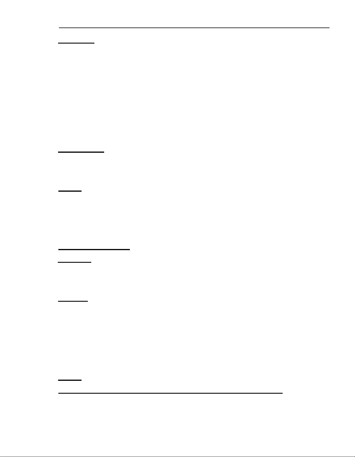
If possible the installation of a 12 Volt operated refrigerator should be completed
with a relay mounted either in the car or in the vehicle (see diagram). This relay
will automatically cut out the refrigerator when the car motor is stopped.
Page 6
6
BREAKER
POINT
CAUTION
Do not operate therefrigerator on 12 Volt
when the vehicle is
out of battery in a rather short time.
If possible the installation of a 12Volt ope-
rated
refrigator should be completedwith
a relay mounted either in the car or in the
vehicle (see diagram). This
tomaticallycut out the refrigeratorwhen
the
car
motor is stopped.
parked.You
realy
will run
will au-
The figures below are guiding valuer calculated in consideration of
0.5
V voltage drop (about 7
without taking into account the losses at the terminals,
I
<-
r
I
I
1
I
I
I
RELAY
----
1
I
>
-
I
REFR.
I
I
I
I--
’
z
Fig.
1
%
input loss) in the connection cables
AWG
14
12
10
8
6
Maximum length of two conductor cable in feet from
power supply
95
w
28
45
72
125 W
150 w
21
34
54 45
87 72
17
28
175 w
15
24
38
62
225
11
18
30
48
W
99 77
Maximum length of two conductor cable in meter from
power supply
175 w
9.0
13.5
22.5
2.5
4
6
10
1.5
150
95 w
6.0
125 W
4.5
w
10.5 7.5 6.5 5.5 4.0
16.5
25.0
12.5
18.5
32.0
10.5
15.5
26.5
(solid cooper wire)
275 W
24
39
62
dmm
1.628
2.052
2.588
3
.264
6.115
225 w 275 W
-
6.5
10.0
5.5
8.0
17.0 14.0
AWG
in mm
Area
2.082
3.307
5.260
8.367
13.299
mn2
Page 7
Special hints
7
The refrigerator must be installed in a
stantial enclosure and
must
be level. A
sub-
spirit Level is supplied with each refrigerator and by placing it in the freezer compartment,
the refrigerator can be leveled
both ways front to back and side to side.
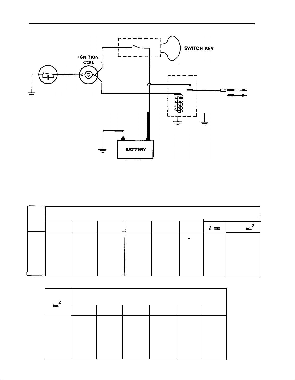
When installing the refrigerator in the
enclosure,
care should be taken to ensure a
complete sealing between the front frame of
the refrigerator and the top, sides and
bottom of the enclosure, For this purpose a
length of sealing strip is delivered with
each refrigerator. The sealing strips should
be applied to the rear surfaces of the front
frame of the refrigerator. See fig, 2.
(RM24
is supplied with this sealing already
fitted on the front frame of the refrigerator).
Be careful not to damage the sealing strip
applied to the bottom of the enclosure when
the refrigerator is put in place.
Any space between the counter or storage
area and the top of the refrigerator must
be blocked. The heat produced at the rear
of the refrigerator will otherwise become
trapped in this space making the top of
the refrigerator hot and reducing the
efficiency of the refrigerator,
r
Fig.
2
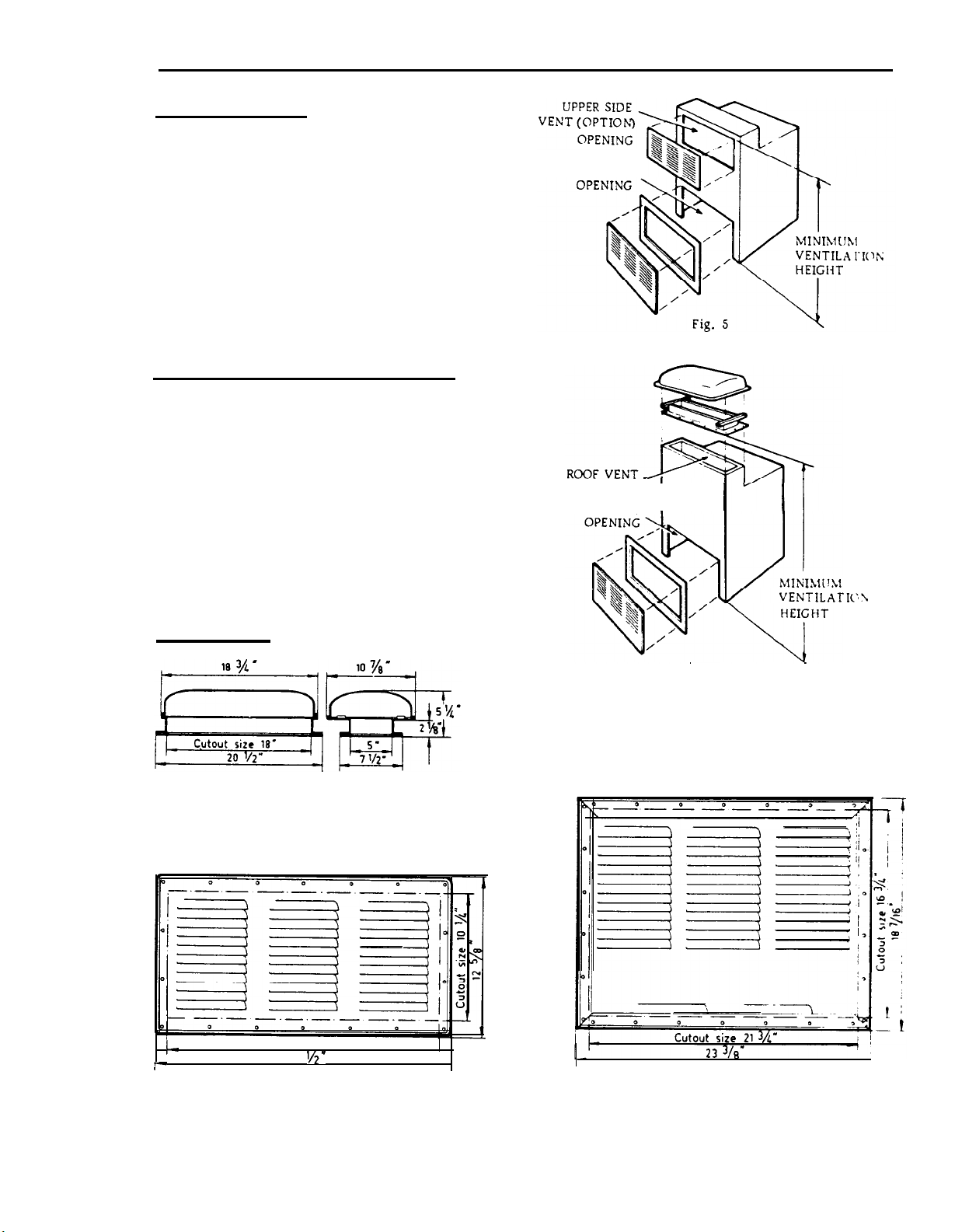
Approved
installations
Approved installations require one roof vent and one lower side vent
as optional,one upper side vent and one lower side vent, as shown in
the figures 4,
Kit No. 1
5
and 6.
comprising:
Upper side vent
(Dometic
123)
Lower side vent (Dometic 183)
Kit No. 2
Kit No. 3
comprising:
comprising:
Upper side vent
Lower side vent (Dometic
Roof vent
(Dometic
Lower side vent
(Dometic RM122)
RM2217)
V 2019)
(Dometic
RM2217)
Page 8
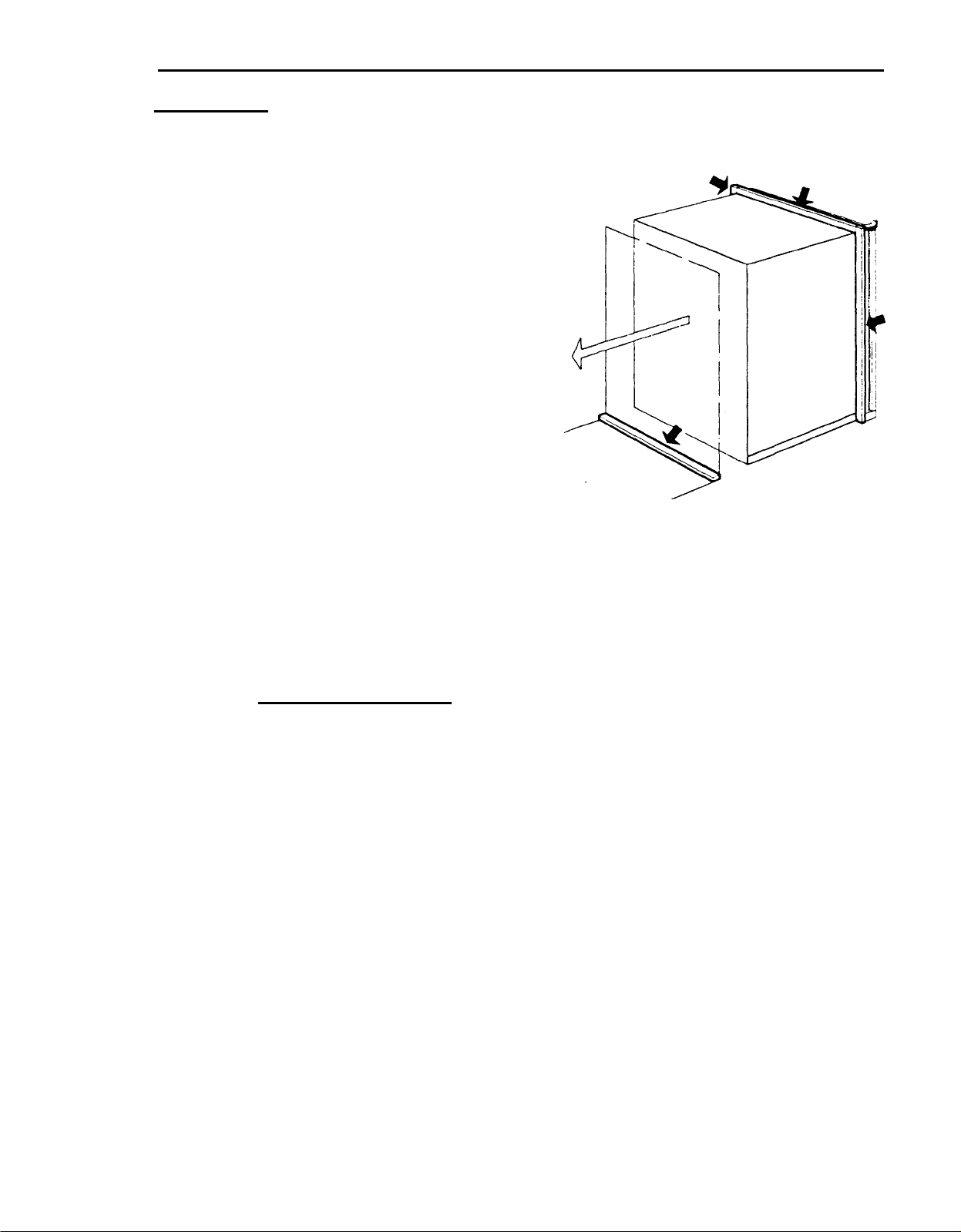
8
When installing the refrigerators full consideration should be taken to the sealing
instructions and the specified minimum clearances and ventilation heights tabled
below:
MINIMUM INSTALLATION CLEARANCES IN INCHES
Refrigerator model
RM66
RM76
RM67
RM77
Clearances on
sides,
bottom
top and
Figure showing
location of the
clearances
the
Clearance A from
the rear of storage
compartment
Clearance B from
rear of
condenser
Fig.
3
MINIMUM
Refrigerator
model
KM24
VENTILATION
HEIGHT
FIGURES
Kit No, 1
22
9/16”
RM36C
RM46,
RM47
RM66, RM67
RM76, RM77
Clearance C on
top of
condenser
Installation type
Kit No. 2
37
l/16”
39
5/8”
47
l/2”
70
l/4”
1
See minimum ventilation
height figures
Kit No. 3
29”
32”
41”
59”
PROPER VENTING IS REQUIRED TO ENSURE BEST PERFORMANCE
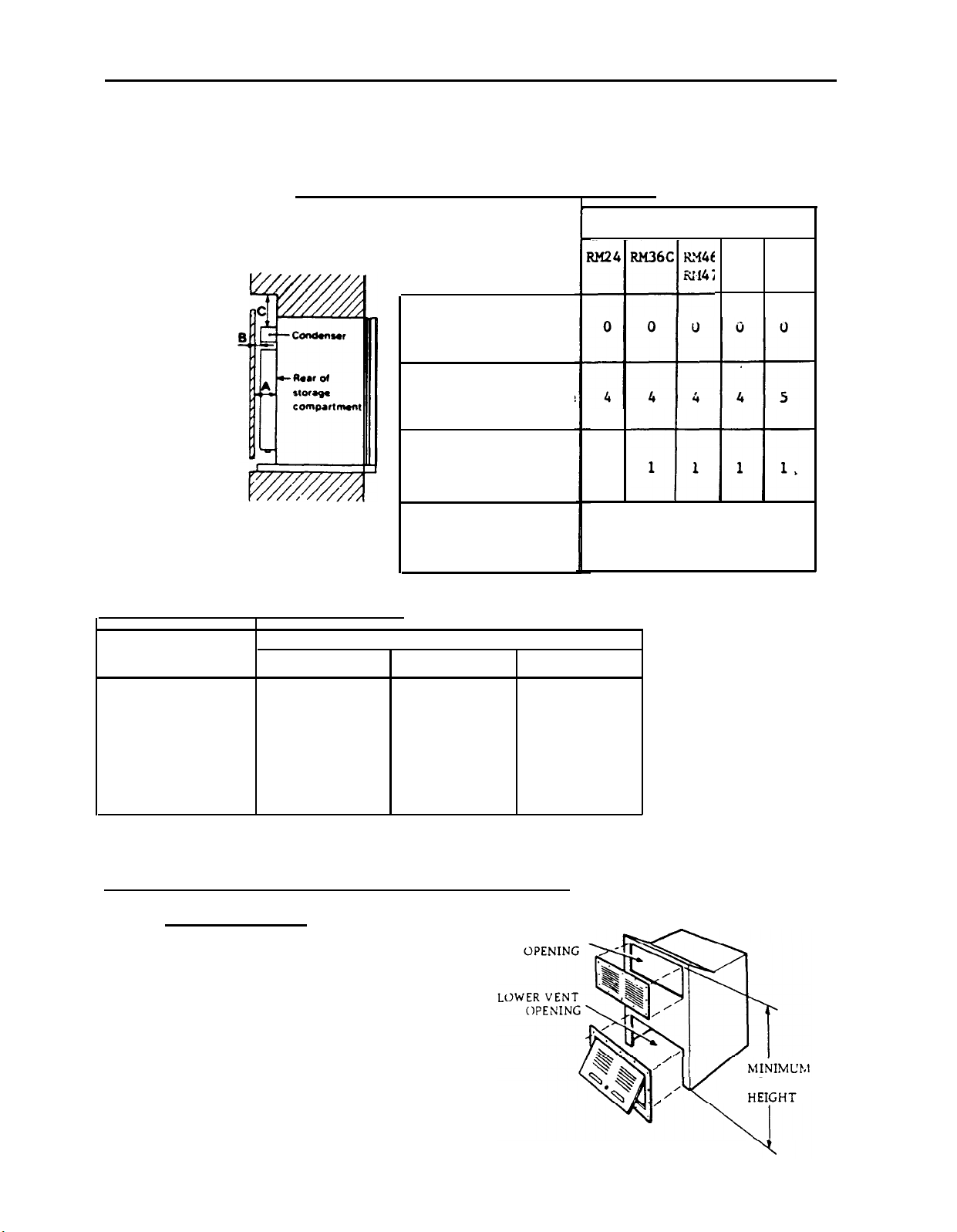
Kit No. 1
comprising:
Upper side vent
Lower side vent
(see Fig. 4)
-
RM24
(Dometic
(Dometic 183)
123)
UPPER VENT
I
I
Fig.
/
VENTILATIOX
/
4
Page 9
9
Kit No. 2 -
RM36C
comprising:
Upper side vent
Lover side vent
(see Fig.
Kit No. 3
5)
- RM36C,
(Dometic RM122)
(Dometic RM2217)
RM46, RM47
RM66, RM67,
RM76,
comprising:
Roof vent
Lover side vent
(see Fig.
(Dometic
V 2019)
(Dometic RM2217)
6)
Dimensions pertaining to
the installation are shown
under measurements.
RM77
LOWER VENT
OPENING
LOWER VENT
-
I
VENTILATK:\
VENTING MEANS
Fig. 1
Roof vent for Kit No. 3
Dometic
I-
c-
V 2019
Cutout size 21”
23
Fig.
‘/2’
8
Upper side vent, Kit No. 2
Dometic RM122
Fig. 6
1
Fig. 9
Lover vent, Kits No, 2
\
and No, 3
Dometic RM2217
Page 10
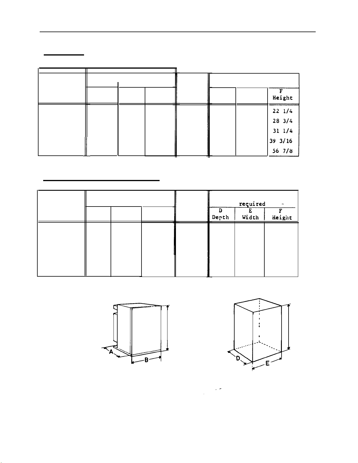
10
MEASUREMENTS
Cabinet and recess dimensions in inches.
r
Cabinet
Refrigerator
models
Overall
A
Depth
dimens
ons
B
Width
C
Height
Door
pro-
jection
Built-in space
required
D
Depth
Width
E
RM24
RM36C
RM46,
RM47
RM66, RM67
RM76,
RM77
18
217/8
24
24 7/8
24
ii
13/16
7/8
5/8
19
20
21
21
23
l/8
l/4
9/16
9/16
7/16
22l/8
283/8
30
7/8
13/16
38
56l/2
Cabinet and recess dimensions in mm.
Cabinet
Refrigerator
models
RM24
RM36C
RM46,
RM47
RM66,RM67
RM76,
RM77
Overall
A
Depth
478
Width
486
556 513
631
547
631 547
625
595
dimen
B
ions
C
Height
562
720
785
985
1435
1
7/16
1
3/4
1
3/4
1
3/4
1
3/4
Door
pro-
jection
37
45
45
45
45
18
20
23
23
23
l/4
l/4
l/4
l/4
5/8
19
200
217/8
21 7/8
23
13/16
l/4
l/4
Built-in space
OIPIh
460
515
590
489
521
555
590 555
599
605
572
729
794
994
1444
Cabinet overall dimensions
-e
Built-in space
C
Fig. 10 Fig. 11
requirements
,
I
0
I
I
F
Page 11
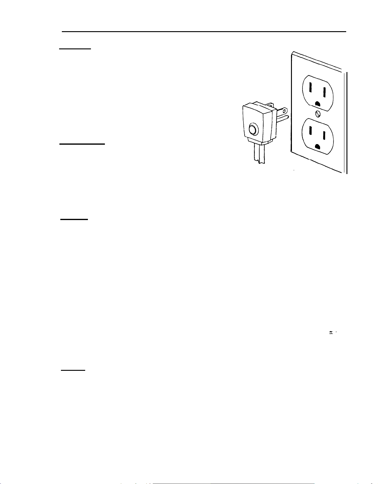
Grounding
It is imperative, for personal safety, that
all refrigerators equipped with a three-prong
(Grounding) plug be used only with properly
grounded wall receptacles, See fig. 12.
If there is any doubt as to whether the wall
receptacle is properly grounded, the customer
should have it checked by a qualified electrician. DO NOT, UNDER ANY CIRCUMSTANCES,
CUT OR REMOVE THE
THIRD
(GROUND) PRONG FROM
THE POWER CORD PLUG,
11
Proper
fusing
Fusing of any circuit should be in accordance
with local electrical code, The refrigerator
should be plugged into a separate branch
circuit, Use of extension cords should be
Fig.
avoided on refrigeration equipment. In the
12
event an extension cord is used, the cord
should not exceed six feet and be of sixteen
gauge or heavier wire.
Gas line
L.P. gas is highly inflammable and it is of extreme importance to ensure that all
joints in piping carrying the gas from the storage bottle to the burner on the
absolutely gas tight. Check at least twice a
refrigerator are
-
and will
remain
-
year.
The gas line should be free
After installation, the gas
checked for leaks up to the
of kinks and sharp ends.
should be turned on and all joints in the gas line
burner using soapy water. This check should be repeated
periodically ,
Do not fit any extension tothe top of the flue. This is not only unnecessary, but
can create draught conditions which can adversely affect correct combustion at the
burner and consequently,
the functioning of the cooling unit,
The refrigerator should be operated at an inlet gas pressure of
Incoming gas pressure is controlled by the pressure regulator on the
11” W.G. (280 IT.. W.G
propane/butane
bottle.
CAUTION
When connecting the gas line to the gas cock on the
:
gas/el
equipment
at the rear of
the refrigerator,use a back-up wrench to prevent undue rotation of the gas cock.
It is of utmost importance for correct functioning of the
RM46,
RM47,
RM66, RM67 and RM76, RM77, that the gas cock lever is correctly engaged
in the slot
"E"
(see Fig,
16) on the plastic driving disc “A” of the
gas/el
control on
gas/el
control
RM36C,
mechanism.
Page 12
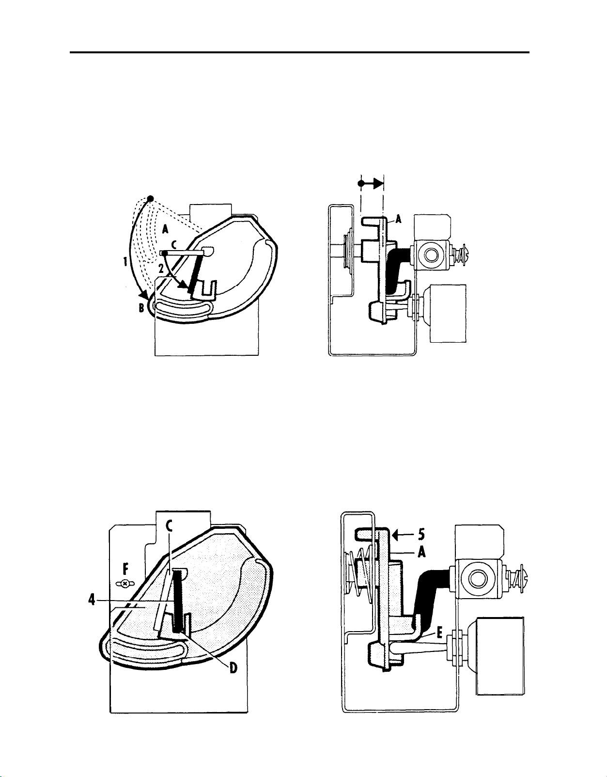
12
If for
disc,
1.
2.
3.
any reason
the gas cock lever has come off position in the driving plastic
check alignment, Proceed as follows:
Turn
Turn
downwards
downwards
the driving plastic disc "A" to stop
the lever
"C"
of the gas cock as far as possible (fig, 13).
Pull the driving disc "A" outwards (fig. 14).
.3.
WI
. .
"B"
(see fig. 13).
Fig.
13
Turn
4.
3.
the lever
Release the driving disc which is then pulled inwards by spring action, whereby
the lever of the gas cock snaps into its slot
"C"
of the gas cock into vertical position
Fig.
14
"D"
(see fig. 15).
"E"
on the driving disc
"A"
(fig. 16).
iiote:
If
the
gas cock lever
disc "A",
sluggishly
adjust the two fastening screws
snaps into its position in the driving
"F"
of the mechanism.
Fig.
Fig.
15
16
Page 13
Combustible Material Storage
Combustible material such as ether, gasoline, hexane, naphtha, benzine, butane,
propane, alcohols,
stored in a refrigerator. These materials are classified as hazardous and constitute
a dangerous application of the refrigerator.
Keeping sealed system area free of litter,
acitone,
benzol, lacquer solvent,
or natural gas SHOULD NOT BE
13
Litter,including paper or rags,
not be stored in the area of the absorption system behind the refrigerator. Often
rags or paper towels (etc.) will be saturated with a combustible cleaning solvent,
Such materials must not be allowed in the space behind the refrigerator
the gas flame which
is operated on electricity,litter must not be stored in this area because of
heat given off by the refrigerating absorption system. It is also of utmost
importance that the air circulation round the unit’s parts behind the cabinet is
unrestricted.
of the refrigeration unit.
3..
UNUSED OR ABANDONED REFRIGERATORS
An unused or abandoned refrigerator or freezer in your basement or garage poses a
hazard to children.
When you discard a refrigerator or freezer . . .
COMPLETELY REMOVE THE DOOR. In many municipalities,
takes only a moment with a screwdriver.
as you can,have the old unit carted away and destroyed before it attracts a
child’s curiosity and endangers his life.
4.
TO CHANGE THE DOOR PANELS
on models
RM66,
Good refrigeration performance is dependent upon adequate ventilation
RM36C, RM46, RM47,
RM67,
RM76, RM77
is
used to power the refrigerator. Even when the refrigerator
woodshavings or other combustible material, should
this is the law. At any rate, it
Do this as soon as possible.
because
Also, as soon
of
Remove the screws holding one side
member of the aluminium door frame.
Pull out the outer door panel, re-
place panel,reassemble and refit
the door,
Panel dimensions
18
RM36C 257/
RM46,RM47 2725/32'”
RM66,RM67 35
RM76,RM77
RM76,RM77 41
11
32”
21/32"”
11/32”
l/32”
253/ 32”
27
21/32”
35
17/32”
11
l/4”
40
15/16”
i
20
21
21
23
23
Width
Max.
3/16” 18l/8”
5/32” 201/32”
l/2”
l/2”
13/16” 233/4”
13/16” 233/4”
Min.
21 3/8"
21
3/8”
Thick-
ness
Max,
l/8”
5/32”
5/
32”
5/32”
l/8”
l/8”
Page 14
14
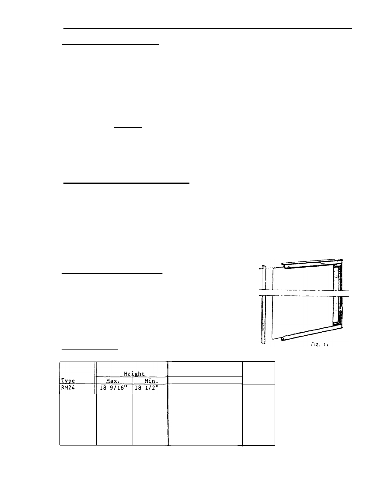
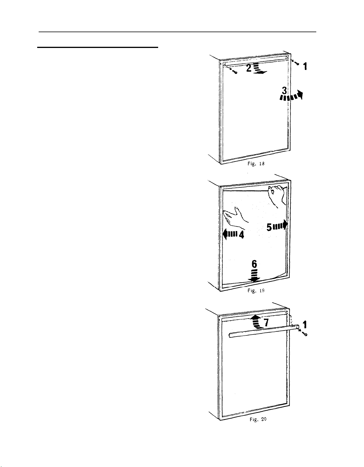
To change the door panel. Model RM24.
Remove the top decoration strip
A.
with its two screws
(1).
pull outward
on the top of the door panel and lift
slightly
to free the panel from the
bottom groove.
If a new panel is being installed,
B.
assure
that
it is the same size as
the old panel,
Install the new panel by inserting
c.
one of the vertical sides of the
panel into the groove of the door
frame (4).
Bend the panel gently so that the free
D.
side of the panel can be slipped into
corresponding groove of the door
frame (5).
Push the panel downwards so that the
E.
lower horizontal edge of the panel
is fitted in the bottom groove (6).
Between the upper edge of the panel
F.
and the door frame there is now
a gap which should be covered by the
decoration strip,
(2)
Put the strip across the door so that
G.
the gap is covered and push it up-
wards (7). The tabs on the inside of
the strip should fit in behind the
flange of the door frame.
When put in place, secure the deco-
H.
ration strip by means of the two
screws (1).
The panel is then locked
in proper position.
Page 15
5.
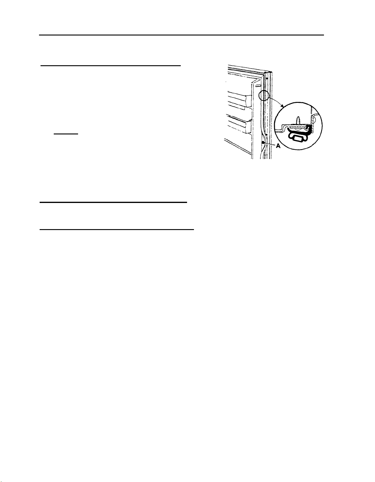
REPLACEMENT OF DOOR GASKET ON
The construction of the door complete is an aluminium extruded door frame foamed
in place with the door pan and magnetic door gasket, i.e. the door pan cannot be
removed,
RM24
15
Therefore,
the above model. The gasket is delivered in a set consisting of the gasket and of
necessary fastening strips and
The replacement is made as follows:
Remove the door and place it with its front downwards on a soft surface.
1.
Cut off the defective door sealing gasket,
2.
possible).
Drill
3.
door pan as pattern.
Fit the sealing gasket as shown in the figure 21.
4.
Fit the door and adjust it so that it seals properly.
5,
a special door sealing gasket for service purposes has been produced for
screws and is ordered under part No.
(Cut as near to the door pan as
7/64”
holes for the screws of the fastening strips. Use the holes of the
290 07 33-00/3.
Fig. 21
Page 16
16
Replacement of door gasket on models
RM36C, RM46, RM47, RM66, RM67, RM76, RM77
Remove the door shelves.
1.
Unscrew the upper hinge bolt, incline the door
2.
outwards and lift off the door.
Lay door on flat surface with door pan facing
3.
up.
CAUTION:
The
4.
6.
REPLACEMENT OF EVAPORATOR DOOR CASKET -
1.
2.
screws
hidden by the door gasket. Pull the door
gasket to one side and remove all screws "A"
(see fig.
REPLACEMENT OF EVAPORATOR DOOR ON
Unscrew the retainer (fig. 25) and remove the door.
Put evaporator door on a flat surface vith the sealing gasket up,
Pry the door front away from the inner pan by means of a screwdriver (fig.
Be sure to protect door panel
prevent scratches and dents.
holding the door pan in place are
24)
from the door plate.
RM36C
to
RM36C
Fig. 24
26).
Page 17

CAUTION: It is of great importance that the screwdriver is applied in front of
one of the plastic tongues which hold the inner panel and the door
front together.
Replace the sealing gasket round the inner panel and snap the inner panel and
3.
the door front together.
Mount the evaporator door and refit its retainer.
4.
17
Fig. 25
REPLACEMENT OF EVAPORATOR DOOR ON RM46,
Push the carrier (A) inwards by means of a blunt mandrel or pin (fig. 27) and
1.
RM47,
RM66, RM67
remove the shutter.
Pry the spring housings
2.
and turn the spring housings downwards
3.
Mount the new shutter in close position first on one side, making sure that the
cross slots engage in the cross on the hinge plate
Press the carrier on the opposite side so that the hinge plate on the shutter
4.
can be pushed over it.
5.
Turn the spring housings round and up until the small tag
(B
fig.
27) away from the lining so that it snaps out
180’
(fig. 28).
See that the crosses engage.
(C
fig.
27).
(A
fig. 28) snaps
into the slot in the lining.
-’
Fig.
27
Fig.
28
Page 18

18
REPLACEMENT OF EVAPORATOR DOOR GASKET ON
RM46,
1. Remove the door as previously described.
RM47,
RM66, RM67
Unscrew
2.
3. Put shutter on a flat surface with the
sealing gasket up.
4. Pry the shutter front avay from the inner
pan by means of a screwdriver (fig. 29).
CAUTION:
the
one of the plastic tongues (B fig. 29)
which hold the inner panel and the
shutter front together.
Replace the sealing gasket round the inner
5.
panel and snap the inner panel with
sealing gasket into the shutter front
until the tongues snap in position.
Mount the shutter as described above,
6.
7
.
TO CHANGE THE DOOR FROM RIGHT TO LEFT-HAND OPENING AND VICE VERSA -
the hinge plates (A fig. 29).
It is of great importance that
screwdriver
is applied in front of
RM24
With the door closed,
(a)
(b)
(c)
upper hinge arm and the four
screvs
screv
the door seal can be adjusted. Loosen the front
Fig. 30
Page 19

19
To change the
RM36C, RM46,
Unscrew and remove upper hinge bolt (A fig.
1.
door from
RM47,
right to left-hand opening and vice versa on models
RM66, RM67
31),
incline the door outwards and
lift off the door. (Check that washer and nylon bushings are in the right
positions).
Move the lower hinge bolt (B) to the opposite side.
2.
\
Fig. 31
%A
,
4’
/
/
,
Fig.
32
B
Remove the plastic travel latch (A fig. 32) by means ofturning it towards the
3.
cabinet opening and slide it out from its slot in the hinge plate (B). Turn the
travel latch the opposite way and fit it on the hinge plate on the other side
of the cabinet. When the travel latch is in locked position the fluted side of
the latchshould face the cabinet opening.
Refit thedoor and the upper hinge bolt,
4.
CAUTION
:
Check that the door closes easily and that the door gasket seals
on all sides, If necessary,adjust by resetting the top hinge.
To change the door from right to left-hand opening and vice versa on
RM76
1. Unscrew and remove the upper hinge bolt (A)
F
on the freezer door,
incline the door out-
wards and lift off the door (fig. 33).
Remove the middle hinge bolt (B) and lift off
2.
---\‘-
\
the cabinet door.
Move the lower hinge bolt
3.
(C)
to the opposite
E-
side.
4. Unscrew the middle hinge (D) and the holder
with travel latch
(E)
and change their
positions to opposite side.
RM77
well
A
5. Refit the cabinet door and the middle hinge
bolt.
6. Refit the freezer door and the upper hinge
bolt,
CAUTION:
Check that the door closes easily and
that the door gaskets seal well on
all sides.
s
Page 20

20
8..
THE ABSORPTION REFRIGERATOR SYSTEM
Sealed system construction
The sealed system of the absorption refrigerator is constructed of velded steel
piping which contains the refrigerant charge.
hydrogen and
water.
There are no moving
The charge consists of ammonia,
parts associated
vith the absorption system,
CAUTION:
When servicing an absorption system refrigerator,
piping.
immediately with clear vater.
vessel.
Cooling Unit 257A
gas/electric
for model RM24
without defrosting device
Should a break occur and ammonia contact the skin, wash the affected area
Do not attempt to open the valve on the absorber
valve is covered with a plastic cap and should never be removed.
The
-
operation
do not puncture
Fig. 34
or
break the
Cooling Unit 270A
gas/electric operation
for model
RM36C
vithout defrosting device
WATER SEPERATOR
Fig.
CONDENSER
EVAPORATOR
35
Page 21

WATER SEPERATOR
21
Cooling Unit
gas/electrrc
315A
operation
for model RN47
with defrosting device
Cooling Unit
gas/electric
317A
operation
for model RM46
without defrosting device
Cooling Unit
gas/electric
for model
351A
operation
RM67
with defrosting device
Fig. 36
Cooling Unit 352A
gas/electric
for model
operation
RM66
without defrosting device
Cooling Unit
gas/electric
513A
operation
for model RM77
with defrosting device
Cooling Unit 515A
gas/electric
for model
operation
RM76
without defrosting device
Page 22

22
9.
OPERATION ANALYSIS
It is obviously important that all external factors affecting the unit should be
checked properly before a unit is condemned as faulty and that emphasis has been
placed upon the necessity for correct installation, upright refrigerator, correct
heat input, baffle position, etc.Check the size and the wattage of the electric
heater and make sure that the heater element is inserted to its full length in its
pocket. If the electric heater is only partly inserted, the heat distribution will
be incorrect ,
operating on electricity, The
heat input either on electric or on gas operation and also if the refrigerator had
been operating in an off-level position or with inadequate ventilation.
causing an excessive vaporizing of the ammonia within the boiler when
FOR
COOLING UNIT
same symptom can show up with too much or too little
If an excessive vaporizing of the
reasons above,the liquid mixture in the boiler becomes very weak and the pump will
cease to operate, which means that the circulation of liquid stops with the result
that the evaporator inside the cabinet ceases to produce cooling,
Such a blockage of the unit in the liquid circuit is most usually made evident by
signs of overheating on the vapour pipe leading from the boiler to the condenser,
the paint on this pipe being blistered and the metal becoming
To remedy this fault it is recommended to remove the unit or refrigerator complete
whenever possible and to allow sufficient time to cool down the unit. Turn the unit
or refrigerator upside down several times,
can be mixed with the liquid in the boiler.
balance to the unit.
The temperatures on various parts of a unit vary continuously
on thermostatic control and it is impossible
given unless the refrigerator has been operating continuously on fully correct heat
input for at least 5 hours,and preferably 12 hours, prior to examination. In many
cases this can be arranged by a telephone call to the customer, asking him to switch
the thermostat to
operation on "MAX” the performance is satisfactory, the unit is not at fault unless
the complaint is one of varying or intermittent performance, In this connection the
room temperature at the time of the complaint must be considered, as a unit which is
satisfactory at an ambient temperature of
95’F
(+35’C).
“MAX”
on the day before the inspection call, If after 12 hours’
ammonia
within the boiler occurs due to the
discoloured.
so that the liquid in the absorber vessel
This procedure will restore the liquid
when it is operating
to base a judgment on the symptoms
65’F (+18OC)
may not be satisfactory at
In cases where satisfactory performance is obtained on
settings, the thermostat is to be suspected,
“?lAX”
When a normal unit is working on
bottom than it is at the top,
pipe from the boiler to the condenser will be warm, bearably to the hand, at the
bend where it joins the condenser,
boiler end,
Unit filling valve
The needle valve used for admitting the filling charge to a cooling unit is fitted
to the unit’s absorber vessel and is covered by an aluminium or plastic
strictly applied provision of the warranty extended on the unit to the customer,
that any interference with the filling valve
Unsatisfactory unit performance due to an ammonia leak can be determined in the
of a visible leak by traces of a yellow deposit at the point where the
escaping,
ammonia
If there is a leak on the evaporator inside the cabinet, a smell of
may be noticeable,
The absorber vessel will be warmer, The vapour cooling
the absorber coil will be warmer at the
with a gradual rise in temperature towards the
will
automatically void the warranty.
“MAX”
but not on other
cap. It is
ammonia
case
is
Page 23

10.
COOLING UNIT REPLACEMENT RM24
If it is necessary to replace the cooling unit, proceed as follows:
Turn off the gas b ttle.
1.
Disconnect gas line to inlet valve,
2.
23
CAUTION
3.
Unplug the electric line.
Check that refrigerator is empty and remove ice tray.
4.
Remove the evaporator cover with its flap
5.
which will release it from the evaporator. (See Fig.
Release the capillary clamp by removing the plastic rivet “B” and straighten
6.
the thermostat capillary tubes.
Remove the plastic cover “C” by means of pulling it towards the right hand
7.
side which will release it from the evaporator window.
8.
Remove the refrigerator from its recess and place its front downwards on
soft surf ace.
9.
Pull out the capillary tubes.
10.
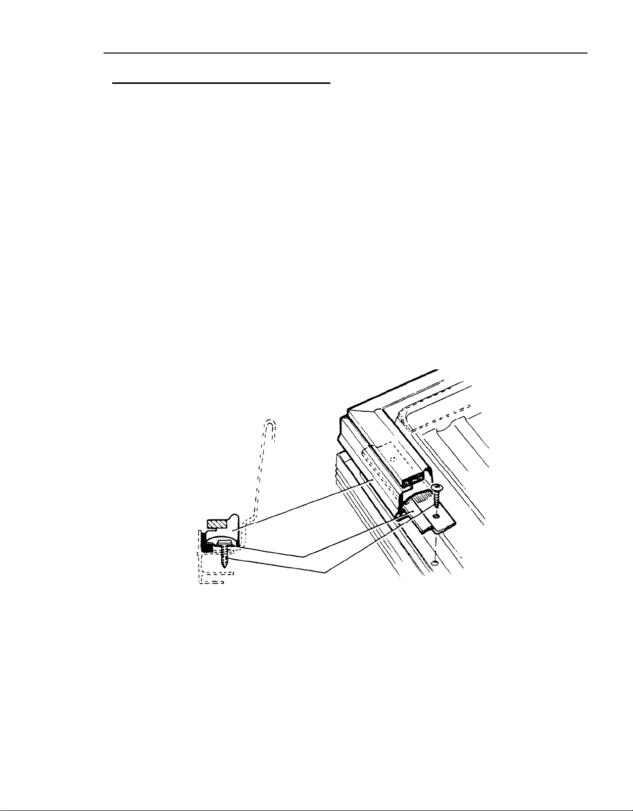
Loosen mount screws “A” holding the blow out kit, Fig. 40.
Remove the heater (see Fig. 13).
11.
Remove mount screws “B” holding the unit.
12.
Use a back-up wrench to prevent undue rotation.
:
“A” by means of pulling it outwards
39).
i
13.
Loosen screws
“D” holding the burner housing and remove the gas equipment,
14.
To replace unit, reverse
“C” holding the bracket for the
above procedure,
gas/e1
equipment and the screws
Fig. 39
Fig. 40
Page 24

24
COOLING UN IT REPLACEMENT
Remove the refrigerator from its recess as follows:
Check that refrigerator is empty and remove
1.
ice tray.
Turn off gas bottle.
2.
Disconnect gas line to inlet valve
3.
CAUTION: Use a backup wrench to prevent
undue rotation.
Unplug the electric line from the trailer
4.
outlet.
Remove the 4 screws in rear front f fame.
5.
Check for any additional screws which the
6.
vehicle manufacturer may have used to
fasten the refrigerator in place.
Carefully slide the refrigerator straight
7.
out of its recess.
- RM36C, RM46, RM47, RM66, RM67
c
/I
i
RM36c
Fig. 41
I
To remove the cooling unit from the cabinet,
proceed as follows:
Place the refrigerator on a work bench of
1.
suitable height.
Remove the thermostat capillary tubes by
2.
loosening the two screws “A” on the
evaporator fins (Fig. 41 and fig.
CAUTION: The locations of the thermostat
capillary tubes should be noted at this
time for relocation later on. The tubes
must be placed in the right position,
otherwise,
Remove the two sealing plugs for capillary
3.
tubes,
cabinet,and straighten the tubes.
Remove the capillary tubes by going to the
4.
back of the refrigerator and gently pulling
the tubes straight out.
Remove the 4 screws
5.
evaporator fins
RM66,
freezer compartment).
improper performance may result.
one on the back and one inside the
“B”
and take away the
“C”.
(On RM46,
RM67,
6 screws and 2 screws in the
RM47
42).
and
RM66
RM67
Fig. 42
Remove the plastic cover “A” (Fig. 43) by
6.
means of pulling it upwards on the right
hand side which will release it from the
cabinet liner (only on
RM36C).
Fig. 43
Page 25

Remove the connection block cover on the side of the boiler case and disconnect
7,
the two electrical wires where they join the heater leads in the connection
block.
Remove the grounding screws “A” (see Fig.
8.
46) on the lower part of the boiler
case.
Remove the flue and the flue baffle.
9.
Remove the screws “B” (see Fig.
10.
46) holding the absorption unit onto the back of
the cabinet.
Release the piezo electrode.
11.
Carefully slide absorption unit out of cabinet. Be careful not to damage the
12.
inner liner of the cabinet,
To replace absorption unit, reverse above procedure.
13.
CAUTION :
25
Be sure to apply sealing permagum “A” (fig. 44 and fig. 45) on the unit mounting
1.
plate and on the high evaporator inlet tube (B).
2.
Be sure to fit insulation pad
Be sure to apply proper amount of “Thermal Mastic” on the evaporator coil
3.
(fig. 44 and fig.
When fitting the evaporator flange(s) be sure to tighten the screws properly in
4.
45).
(C)
and sealing
(D)
(only on
RM36C).
order to obtain a perfect contact between the evaporator coil and evaporator
flange, otherwise improper cabinet performance may result.
“E”
/’
RM36C
Fig.
44
RM46, RM47
RM66,
Fig.
15
RM67
Page 26

26
Fig. 46
Replacement of absorption unit on models RM76,
When
replacing the absorption unit it will be necessary to remove the refrigerator
from
its recess (paragraph 10).
Remove the 6 screws at the bottom of the freezer compartment (“A” fig. 47).
1.
2.
Remove the thermostat capillary tubes by loosening the two screws “B” on the
RM77
evaporator fins (fig. 47).
CAUTION :
The locations of the thermostat capillary tubes should be noted at this time
for relocation later on.
The tubes must be replaced in the right position,
otherwise improper performance may result,
Remove the two sealing plugs for capillary tubes, one on the back and one in-
3.
side the cabinet,
Remove the capillary tubes by going to the back of the refrigerator and gently
4.
and straighten the tubes out.
pulling the tubes straight out,
Page 27

27
Fig.
47
Remove the connection block cover on the side of the boiler case and disconnect
5.
Fig.
48
the two electrical wires where they join the heater leads in the connection
block.
Remove the grounding screw,
6.
Remove the flue and the flue baffle,
7.
Remove the screws
8.
“B” holding the absorption unit onto the back of the
refrigerator (fig. 46).
Release the Piezo electrode from burner housing.
9.
Remove the fastening screw on the burner housing and remove the
10.
burner housing from the boiler case,
Carefully slide absorption unit straight out of the cabinet.
11.
CAUTION
:
Be careful not to damage the inner liner and the locations of the fastening
strips (“A” fig. 48) on the evaporator should be noted at this time as they
have to be fitted on the new unit,
To replace absorption unit, reverse above procedure.
12.
CAUTION
-_
Be sure to apply sealing permagum
:
(“B”
fig.
48) on the unit mounting plate.
Be sure to fit the fastening brackets (A) on the evaporator coils in the right
positions,
otherwise it will be difficult to refit the 6 fastening screws
inside the freezer.
Page 28

28
11.
GAS EQUIPMENT
FOR
RM24
Item
No.
1
2
3
4
5
6
7
8
9
10
11
12
13
14
15
16
17
18
19
20
‘J
1 2 3 4
Description
S.I.T.
thermo-electric flame failure device
Lock nut
Pressure test connection
Housing for test connection
Union nut
Olive
Gas pipe
Burner jet
Burner pipe
Filter with nipple & nut
Thermostat
Ranco
V35
By-pass screw
Thermos tat knob
Screw
Indicator
Thermo-coup le
Lock nut
Washer
Distance tube
Distance nut
Fig. 49
65 7
Item
NO.
21
22
23
24
25
26
27
28
29
30
31
32
33
34
35
36
37
38
39
40
41
Description
Screw
Gas cock
Flint lighter,
compl.
Flint
Spring
Screw
Screw
Screw
Screw
Washer
Spire speed nut
Screw
Baffle
Baffle support wire
Screw
Viewing
Window
Seal for viewer and flint
lighter
Metal shield
Washer
Screw
glass
Page 29

12.
DUAL ELECTRIC EQUIPMENT
12/11OV
FOR RM24
Fig.
SO
Item Description
No.
1
Heater,
2
Terminal block
Cable clamp
3
4
Thermostat knob
Terminal block cover
5
6
Screw
7
Spire speed nut
8
Switch cover
9
Screw
10
Gas cock with bracket
11
Screw
12
Protection tube
Thermostat
13
14
Nut
15
Thermostat cover
16
Screw
17
Plastic rivet
18
Capillary clamp
19
Grommet
20
Screw
21
Clip
22
Switch knob with dial
12/11OV, 95W,
Ranco A50
TYPE 173
27
/ v-12
/
Item
No
l
23
24
25
26
27
28
29
30
31
32
33
34
35
36
37
38
39
Description
I?i
L
Dial
Screw
Nut
Washer
Switch
Cable clamp
Screw
Indicator
Thermostat bracket
Screw
Fastening plate
Insulation
Screw
Terminal
bl
ock
Screw
Insulation
Fuse
10A
v
22
0
ri.
J
Page 30

30
13.
GAS/ELECTRIC EQUIPMENT
(See Fig. 51)
GAS EQUIPMENT PARTS
Flue baffle
1.
Blow out protection
2.
Burner tube
3.
Burner housing
4.
Burner jet
5.
Feeler point
6.
Flame failure safety device
7.
By-pass screw
8.
Gas thermostat
9.
Knob for fuel selector
LO.
Pressure test gage connection
11.
Gas filter
12.
Plugs for capillary tubes
13.
Capillary tube for gas thermostat
14.
Shut-off valve
15.
Push button for lighter
16.
Piezo lighter
17.
Lighter electrode
18.
Knob
19.
20,
21.
for releasing safety device
Knob
for gas thermostat
Fuel selector,
LP-gas/l10 Volts A.C.
lZ/llOV
FOR
RM36C, RM46,
RM47, RM66,
RM67,
RM76,
RM77
ELECTRIC EQUIPMENT PARTS
Flexible cord with moulded plug
22.
Junction box
23.
Electric thermostat
24.
Knob for electric thermostat
25.
Toggle switch (110 Volts operation)
26.
Heater
27.
Capillary tube for electric thermostat
28.
12 VOLTS OPERATION
Terminal block
29.
Fuse
30.
Fuel selector,
31.
Change-over switch, 110 Volts
32.
LP-gas/l10 Volts
A.C./l2
A.C./12
Volts D.C.
Volts D.C.
Page 31

31
27
3
___[____*
2
_
. .
: :
il
i.:.
Fig. 51
Page 32

32
14.
THE GAS THERMOSTAT V- 35
The gas thermostat V-35 consists of three main parts:
sys
Be 1 lows
Mechanism
Valve housing, see fig. 52 and fig.
tern
BY-PASS SCREW
“COLD”
SCREW
53.
AOJUSMENT
Gas inlet
)‘alvc housmg
, Bellows system
TYPE V35
Fig. 52
+
Gas outlet
l_evL
Fig. 53
Mcchbnism housing
Cleaning valve or valve seat in the V-35 thermostat
Dirt on the thermostat gas valve or seat prevents the thermostat valve from
pletely closing,
consequently it lets through some gas when in closed position.
car
This condition may prevent reducing the flame to the required minimum. It will cause
too low cabinet temperature.
to
“0”)
If the flame does not go down to the
This can be controlled by turning the thermostat dial
low
flame (by-pass flame) it will be
necessary to clean the thermostat valve and valve seat. Note: The thermostat will
not close to
at least
S°C
(40 F) .
by-gass
on setting
unless the thermostat bulb is cooled down to
“O”,
Proceed as follows:
a) Remove the plug,
b)
Also check that the size of by-pass screw is in accordance with table below.
spring and valve and clean the valve and the valve seat.
Note:The adjusting screw on the thermostat is preset at the factory and should
-
never be readjusted,
LOST THERMOSTAT CHARGE
If the thermostat control assembly loses its charge, it will become inactive. To
test for a lost charge,
control is set
at a numbered position on its dial:
from its clamp in the evaporator and warm
fails to increase in sire,
while the flame is reduced to minimum and the temperature
capillar:r
the thermostat has
Remove
10s
t its charge and the themostat
thermostat capillary tube
end
with
the hand, If the flame
must be replaced.
Page 33

THERMOSTAT REPLACEMENT
33
To replace the thermos tat,
evaporator fins, Remove the two sealing plugs,
remove capillary from its clamp on the fresh food
one on the outside and one on the
inside of the cabinet. Straighten the capillary and pull it through the cabinet,
Remove the thermostat by
mscrewing
it from the gas filter and the flame failure
safety device.
NOTE :
Always, shut off the gas supply before removing any gas part from the
refrigerator,
By-pass screw sizes and part No.
Mode
1
By-pass
Part No.
screw
RM4
RM36C
RM46
,RM47
RM66 ,RM67
RM76 ,RM77
14
517
517
s17
s17
341913-14/3
172819-02/l
172819-02/l
1728
1+02/l
172819-02/l
Fig. 54
Therm0 couple
(Feylet placed l/3”
15.
THE GAS BURNER (see fig. 55)
The burner has the jet horizontally
located and the burner mixing tube is
formed as a bend with vertical outlet.
The
pri<mary
air inlets are pre-set and
therefore not adjustable. The burner
and the burner holder are made in one
piece.
The burner is provided with the
thenno-
electric failure safety device and the
thermocouple tip is pre-set.
To check for a correct flame, set thermostat to
blue crown at the base of the
Burner jet sizes and input
Mode 1 Butane
RM24
RM36C
RM46,RM47
RM66,@167
RI176 ,RM77
24
34
43
51
5 1
Part
28900
200
26
200
26
200
26
200
26
39-lG/6
60-15/3
60-16/l’
60-1719
60-17/9
flame.
BTU/h.
Ko. Propane
24
43
51
52
53
281)
290
200
200
200
“!AX”.
Part
Ko.
00
35-10/6
26
60-1611
26
60-1719
36
60-1817
26
GO-19/5
into flame)
Fig. 55
Flame should have a bright
Input BTU/h
600
1000
1100
1200
1360
Page 34

34
16.
TEE
FLUE SYSTEM
The flue system consists of the following parts:
1) Central tube (built-in part of the boiler system and cannot be removed)
2) Flue
3) Flue baffle with support wire
vi11
The purpose of the flue system is to provide a draft which
flame in to the central tube and supply sufficient primary
the flame.
The flue baffle which is inserted in the central tube distributes the heat produced
by the burner to the boiler system.
It is important that the correct size of baffle is used and that it is correctly
located in the central tube in order to obtain the best cooling performance. The
size and the distance between the lower end of the baffle and the lower end of the
central tube for different refrigerator models are shown in table,
pull the burner
and secondary air to
Baffle sites, height, and part No.
Part
!Jo.
Baffle Width x Length
Xodel
BM24
RM36C
BM46 ,RM47
BM66 ,BM67
R!!76 .RM77
Flue obstructions
On gas refrigerators, the flue will require cleaning occasionally. To do this it
will be necessary to gain access to the back of the cabinet. When cleaning the flue
proceed as follows:
Unscrew the outer burner shield and the burner housing, release the flue and lift
out the baffle on its support wire from the top of the boiler tube.
From the top,
before putting back in place.
nun
10x100
20x100
20x100 314x4
20x100 3J4x4
20x150 314x6
clean the flue vith a suitable flue brush. Also clean the baffle,
inches
3/a
x
3/4
x
4
4
75 3
75 3
75 3
75 3
75 3
witii
29G
289 00
289
289
17
x) Baffle only
Baffle
support wire
82-00/2
06
28-00/O
28-00/O
00
28-00/O
00
74-0015
21
x:
Fig. 51
An obstruction in the flue will reduce or stop flue draft. Flue obstructions will
cause odors outside refrigerator, slow freezing and higher cabinet temperatures.
Flue stoppages may also cause the flame to burn outside the central tube,
Page 35

THERMOELECTRIC FL&!! FAILURE SAFETY DEVICE (see fig, 58)
17.
All
models equipped with an automatic failure device.
35
L
All
gas operated or combined gas/electric refrigerator models dealt with in this
.
service instruction are equipped with an automatic failure device.
The
purpose of incorporating an automatic flame failure device in the burner assem-
bly is to prevent unburned gas to escape from the burner and to avoid a fire hazard,
if, for some reason or other, the flame has been extinguished or blown out,
The safety device consists of the following parts:
S
I
L
‘1
Fig. 58
1.
Spring loaded push button
Gas valve
2.
Housing
3.
4,
Sensing clement with the hot junction of the
thermocoup le (Feeler)
5.
Enamel insulated copper thread
Electromagnet
6.
Outer tube
7.
Armature
8.
Spring
9.
The
chttimoelectric
By pressing the push button (1) the gas valve (2) is opened and the gas can pass
housing (3) on to the
flame of the burner is lit,
junction of the thermocouple is thus heated and an electric current is generated.
This current passes through the copper wire (5) to the electromagnet (6) and back
through the outer tube (7). As soon as the electric current is generated, the
electromagnet attracts the armature (8) with the valve
be released,
As long as current is flowing, the valOo
burner.
When the flame is extinguished, the heat transfer to the hot junction is
and no electric current is generated.
forced back by the spring (9) and the gas flow through the valve (2) is closed.
Important:
When
held in that position about 10 seconds,
the burner properly,
safety device functions as follows:
burr.:r,
lighting the burner the push button (1) should be pressed f
At the burner the feeler (4) is located. When the gas
some heat is transferred to the feeler
(2).
The push button can
is.
kept open and allows gas to pass co
The
armature (8) with the valve (2) is
otherwise the gas may not get
(4).
The hot
interruFced
tllen
irrl:r 2r.l
c’e
c’en
:‘-e
:o
Page 36

36
REPLACEMENT
ELEMENT OF THE THERMOELECTRIC
FLAME
How
devxce
1.
2.
3. Screw off nut C, remove spacer G and nut D. Release the thcrmo-element E from
4. Bend carefully the new thermo-element to the same shape as the old one. Screw
5.
FAILURE SAFETY
replace the thermo-element of the thermoelectric flame failure safety
(see fig. 59).
l;nscrew plug A f
Loosen the position nut C and lock nut D.
burner housing F.
nut D into the new element,
Put the feeler through the hole in the burner housing F, refit the spacer C and
screw the position nut C tight against the shoulder on the feeler, raking sure
the nut D is free during this operation,
OF
TXE THEM-
DEVICt;
ram
the valve housing B.
8
Fig. 59
6.
Tighten the lock nut D against the burner housing with a small wrench, if
necessary holding nut C vith another wrench,
as in figure.
7, Check that no burrs are inside valve housing B which
Screw plug A onto the valve housing B,
hole in the aluminium cap of the housing,
the valve housing to ensure contact betveen the thermo-element and the
coil vithin the housing,
REPLACEHINT
If the safety valve magnet is defective,
When the safety valve magnet needs replacement
Unscrew the connection plug (A) on the thermocouple from the housing nut
1,
2.
Unscrew the housing nut (B) and remove the defective safety valve
from the housing
3.
Fit a new magnet valve and ensure
that it is properly inserted in
the housing (D).
4.
Fit the housing nut
connection plug (A) and check that
a good contact between the contact
plug (E) on the thermocouple and
the contact (F) on the safety
valve magnet is obtained.
OF
THE
SAFETY VALVE
(3).
(B)
MACXET
and the
taking care not to damage the threaded
it cannot be repaired but
Make sure the feeler is located
nay
cause leaks,
Plug A must be properly tightened to
u.ust
,
proceed as follows (see fig,
magnetic
be replaced,
60).
(B).
ragnet
(C)
Page 37

37
REPLACEMENT
18.
OF
HEATER
The electric heater is positioned in a pocket which is welded to the boiler tube,
A wire clip holds the heater securely in the pocket (see fig. 61).
Wire clip
Fig.
RM36C,
RH66, RM67
61
RM46
RM24, RM76, RM77
Fig. 62
Fig. 63
To replace the heater, first check that the wall plug is disconnected, then unscrew
lock screws
and the upper lid C upwards (on
A (Fig. 62) on the Lower lid B and upper lid C. Push the lid B downwards
RM24
and
RH76,
RM77 remove the plate D, Fig. 63).
On the RM24 model it will also be necessary to remove the blow-out protection flue,
Remove the fibre glass insulation around the heater so that the heater is accessible
for removal. Then bend aside the wire clip keeping the heater in proper position,
disconnect the heater leads from the cord and iemove the heater.
Make sure the new heater is fully inserted before bending back the wire clip (with
caution,or it might snap off), Reset the electric connections. Be careful to put
the Pibre glass insulation back in its proper place and in such a way that the heater
leads will not be in direct contact with hot boiler tubes.
It is essential that the remplacement heater be of the proper rating in order to
provide the correct heat input for the particular model.
The table below shows the correct heater for each model:
Model
RM24
RM36C
RM36C
RM46 ,RM47
RM46
,RM47
RM66
,RM67
RM66
,RM67
RM76
,RM77
Prod. No.
926 39 02
926 45 03
926 45 04
926 46 03
926 46 04
926 47 03
926 47 04
926 48 03
Voltage
12/110
110
12/110
110
12/110
110
12/110
110
810.85
1.1
g/1.1
1.2
10/1.2
1.4
11/1.4
2.1
Watts
95
125
125
135
135
150
150
~ 225
Part No.
290
117
u,v-tiu,/3
173711-01/l
173707-00/l
1737
12-01/g
173708-00/S
1737
1737
13-0117
OS-0017
173074-01/4
Page 38

38
19.
WIRING DIAGRAMS
for
RM24
Switch
1lOV
for
RM36C, RM46, RM47
RM66,
RM67, RM76,RM77
Thermostat
I
Rrd
Black
Terminal
hlnrk
“.__..
-
-
Black
Brown
P-.4
I
I
I
Terminal
block
-
64
Fig.
12
I
I
I
I
Volts
110 Volts
Heating element
l2V/llOV
I
I
‘LP Gos
;
OFF
for
I
RM36C,
Switch
RM46, RM47,
IlOV
AC
WIRING
DIAGRAM
12DChlOAC
Thermostat
RM66,
RM67
Terminal block
Fig. 6.5
Fig.
Heater
I
Heater
66
Page 39

20.
PRESSURE
XEASURING
DEVICES
The pressure at the burner should be checked at the time the refrigerator is started
up, After connecting the pressure gauge, set the thermostat dial at
the gas at the union cock and light tile burner. At the
reading should be
11”
(280 mm).
The L.P. gas is supplied directly to the thermostat
“:Xx”
setting the pressure
from the regulator fitted on the gas bottle at pressure of 11” (280
"i.'ky".
nn).
Turn on
Water U gauge (fig, 67)
The water gauge consists of a glass U tube filled to
pressure is exerted on one side of the gauge, the water on
rrid-point
tha-t
with water.
Khen Eas
side is forced down
and there is a corresponding rise of water on the other side.
Water column pressure per square inch is indicated by the difference of the two
columns of water measured in inches.
A convenient scale reading in inches and tenths of an inch is
rounted
bctveen the
two columns.
When reading the gauge proceed as follows
:
If the gauge is filled with water to zero and the lower column is 5.5 inches
(140
mm)
below zero, the other column will also be 5.5 inches (140
the tvo together 5.5 + 5.5
11 inches (280 mm) water column,
-
IX).
By adding
For accuracy of measurement a vater L’ gauge is far superior to a low pressure gauge.
If a low pressure gauge is used,
it should be checked for accuracy against a water
gauge occasionally .
LOW PRESSURE GAUGE
C
Adopter
WATER U
GAUGE
IF--
.
Part No.
33 87
Fig.
2.9~GOI4
GE
Low pressure gauge (Fischer) (fig, 64)
This gauge is calibrated to read in
“inches of water column pressure”. It is a
standard manometer reading and is colored red.
How to use the pressure gauge
When testing the pressure at the burner,
fig. 67 and fit the hose from the pressure gauge. Use adapter, part
remove the plug indicated with an arrow in
Ko,
33 87 59-031
It is very important that the gas operated refrigerators operate at correct pressure
at the pressure stipulated for the refrigerator.
i.e.
OPERATING
21.
RECOWENDATIONS
Experience over many years shows that incorrect installation and adjustments are
major causes for unsatisfactory refrigeration.
Page 40

40
Unsatisfactory refrigeration also results from improper operation by the user due
to misunderstanding or carelessness.
“INSTRUCTIONS FOR USE” which should be followed to assure the best refrigeration
results. The servicer, as well as the user,
the contents.
A study of the following instructions will help the servicer to better instruct the
user,
22.
The gas and electric controls are located at the rear of the refrigerator and are
accessible through the service door in the wall of the vehicle. The gas shut-off
valve and the electric voltage-change switch are interlocked so that both methods
of operation cannot be inadvertently used at the same time.
23.
and will also help him to answer questions which may be asked.
STARTING THE REFRIGERATOR
GAS OPERATION (See Fig, 70 and
RM24
Each refrigerator contains a pamphlet called
should become thoroughly acquainted with
71)
Ensure that the voltage change switch
1.
Turn the gas valve (C) so that the handle is in line with the valve body and
2.
turn the gas thermostat dial (B) to No. 4 setting.
Push in the blue button
3.
clear air from pipe line.
Still pressing in the button
4.
sharply in a clockwise direction.
Continue pressing in the blue button
5.
it and check that the burner is alight by looking at the flame through the
opening (F) .
If the burner has not lit,
6.
the thermostat dial (B) must first be turned to MAX and returned to its
normal setting only after the burner is alight.
(D)
of the flame failure device for S-10 seconds to
CD),
(A)
is at the “OFF” position.
twist the knob of the flint lighter
(D)
for another 5 seconds, then release
(C)
1
CONN
C
24.
ELECTRIC OPERATION (See Fig,
The RM24 refrigerator can be operated on 12 volts D.C. or
the voltage change switch (A) is set at the appropriate position.
70)
110
volts
A.C.,
provided
Page 41

41
Turn off the gas valve (C), its handle
1.
of the cabinet.
Turn the voltage change switch (A) to the required setting, then connect the
2.
refrigerator to t’
When the electrical supply cord is connected to a 110 volt A.C. supply, tne
voltage on the switch (A) should show
voltage on the switch (A) should show
Turn the electric thermostat knob (E) to No. 4.
3.
HOW TO START THE REFRIGERATOR
RM36C, RM46,
25.
GAS OPERATION (Fig. 72)
26.
To start the refrigerator turn the knob A to position “Casl(.
1.
now opened and the electric circuits are disconnected.
Turn the gas thermostat knob C to setting 4.
2.
Pull the knob D of the flame failure safety device and after 5-10 seconds press
3.
the button E to the piezo lighter.
the reflector F it can be observed that the burner is lit.
RM47 p
appropriate voltage supply,
a
-
RM66,
RM67,
RM76, RM77
vi11
then be pointing avay from the back
llOV,
12V.
The pressing may have to be repeated. Through
when connected to the
battery,
Tne
gas valve is
the
After the burner has been lit keep the knob D in pulled out position for another
4.
5 seconds. Then release the knob and check through the reflector that the
burner stays lit,
Note: After a replacement of the gas container or
gas pipes are likely to be filled with air,
procedure has to be repeated until the air is pushed out of the pipes and
the gas has reached the burner.
a,long
In such a case the lighting
shut-off period the
27.
ELECTRIC OPERATION (Fig, 72)
Check that the attachment plug of the flexible cord is
1.
the main supply. The 12 volt connection is made at the
rear of the refrigerator.
Turn the knob A to “off” position, then press the knob
2.
desired electric position.
correctly connected co
marked terminals at the
in to bottom and turn to
Page 42

3. Turn the thermostat knob G to setting 4.
Kate:
When the refrigerator is equipped for 110 volts and 12 volt operation the
turning movement of the knob A should be made as follows:
In gas OFF position the knob is pressed and turned clockwise to the
12 volt position, If 110 volt operation is desired press once more and
continue the clockwise turning to the 110 volt position marked
28.
LEVELING
“ELEC”.
In the boiler of the cooling unit,
mixture and carried to the finned condenser where it liquefies. The liquid f
the evaporator inside the cabinet where it creates cold by evaporating into a
circulating flow of hydrogen gas.
accumulates forming pockets
pletely,
When the vehicle is stationary it must be leveled to be comfortable to live in. If
the refrigerator is properly installed, i.e.
parallel with the floor,
bubble level (see Fig. 73) is supplied with the refrigerator, The level should be
placed on the ice-tray compartment shelf and the
position of the bubble observed (if necessary,
with the aid of a small mirror), Adjust the position
of the vehicle so that the bubble is in the center
ring of the level.
When the vehicle is on tow,
affect the refrigerator as long as the movement passes either side of level but
when the vehicle is temporarily parked,
be remembered,
29.
1.
in which case, of course, cooling will
TEMPERATURE COh’TROL (TREKfOSTAT)
When the temperature control (thermostat) is set at a higher number, refrige-
rating effect will be increased,
freezing compartment and in the food storage compartment.
vhich
the refrigerator will operate properly, To check this, a
the continuous rolling and pitching movement
ammonia vapor is distilled from an ammonia-water
lO’.JS
If the evaporator is not level the liquid readily
can impair the gas circulation or block it com-
stoe.
the ice-tray compartment shelf is
Fig.
7.7
vi11
not
the sensitivity of the refrigerator should
This
vi11
tend to lover the temperature in the
to
k%en
the temperature control is set at a lower number, refrigerating effect will
be reduced.
When
the temperature control is set at mid-dial position, medium refrigerating
effect will be produced.
2. The position of the temperature control should depend upon the refrigerator
load.
number .A higher setting of the temperature control will be required in summer
than in winter.
The setting of the temperature control determines the action of the thermostat
in relation to freezing compartment temperatures,
30.
THE
On the fresh food evaporator is a sleeve in which the end
of the thermosta: capillary tubing must be inserted. Check
that the capillary tube is firmly in place, If the capillary
tube is not properly inserted in its sleeve
the
burner will operate continuously at maximum flame.
It will cause too low cabinet temperatures.
When
the food load is heavy,
THERTIOSTAT
CAPILWRY TUBE
turn the temperature control to a higher
(see
Fig.
74).
/ 4 ’
Fig. ;A
Page 43

31.
STORING FOOD IN THE
43
REFRXGERATOR
Proper refrigeration requires
1.
partment. Restricted air circulation within the food storage compartment will
cause higher cabinet temperatures, Rearrange foods.
It is also essential that the shelves are not covered with paper or large
2.
storage containers.
Odorous foods or highly flavored foods should always be stored in covered
3.
.
dishes, plastic bags or wrapped in foil or wax paper, to prevent food odors.
Vegetables, lettuce, etc.,
put hot food into the refrigerator.
To reduce frost formation in and on the freezing compartment, cover stored
4.
liquids and moist foods and do not leave the door open longer than necessary,
When the refrigerator is heavily loaded,
5.
peratures to lower, also increasing the ice making time. A very heavy load may
also cause defrosting.
The cabinet interior should be cleaned regularly. Remove the shelves and wash the
lining with lukewarm water to which a little baking soda may be added. Dry
thoroughly,
be used to wash the cooling evaporator,
especially around door frames and door gasket,
free air circulation within the food storage
should be covered to retain their crispness, Xever
it takes longer for refrigerator
Warm
water only should
ice-tra:rs
and shelves.
coar
telh-
-
Plastic dishes may be washed in warm soapy water
the hand. Do not expose them to dry heat, (Never use strong chemicals or abrasive
cleaning materials on any part of the cabinet).
33.
ICE
CLiES
Do not use warm
1.
Faster freezing
2.
34.
TRAVEL
The travel latch may be fitted to hold the door closed while in transit.
35.
TO SHUT OFF THE CABINET
If for any reason refrigeration is not required over a period of weeks, the gas
taps or electric switch should be turned off,
The cabinet and ice trays should be emptied,
ajar,
36.
DOOR SEAL
It is essential, for correct operation, that the door gasket makes a good seal
1.
all around, against the front of the cabinet.
LATCti
water, as it takes longer to freeze.
will result if
precooled
water is used.
not hotter than is bearable to
cleaned
and dried and the door left
-,
The compression of the gasket down the hinge side must not be too great: The
gasket should just contact the front of the cabinet when the door is closed.
This is normally allowed for during manufacturing,
Page 44

44
Failure of the door gasket to contact the front of the cabinet can be determined
visually when the door is closed.
seal,
board feel loose.
Improper door sealing on cabinets can be corrected by slackening the upper and
2.
lower hinge fixing screws and moving the door inwards or outwards as required
until a satisfactory seal is obtained.
If a good seal cannot be obtained, a new gasket should be installed.
It is also essential to check that the cabinet opening through which the freez-
3.
ing compartment enters the cabinet should be properly sealed by sealing
compound, If this seal leaks, warm air enters the cabinet causing high cabinet
temperatures and
37.
ODORS
Odors inside the refrigerator are caused by improper food storage.
inserted between the seal and the cabinet front, Nowhere should the card-
excesskve
INSIDE THE REFRIGERATOR
frost formation on the freezing compartment.
Run a piece of thin cardboard along tne door
They may also be caused by too infrequent cleaning of the food compartment or the
refrigerator has been shut off for some time with the door closed.
ODORS FROM FUMES
38.
Odors outside the refrigerator may be caused by gas leaks.
1.
gas appliances are closed, Test gas connections and all joints in the gas line
with soap and water solution,
leak with an open flame. Use a flashlight when
bubbles caused by leaks. The gas line should be free of kinks and sharp ends.
Turn on gas cock, light burner and test connections between the gas cock and
the burner carefully with soap and water.
Odors outside the refrigerator may be caused by improper burner flame.
2.
The flame touches side of the boiler due to dislocation of the burner. Relocate.
3.
Burner dislocation may also cause smoke and
Burner damaged. Replace.
4.
The flame touches flue baffle. Correct position of baffle.
5.
The flue tube is dirty, Clean the flue,
6.
FLAME
39.
If trouble is encountered with the flame blowing out under specially windy conditions, try to place the vehicle so that the wind does not blow directly into the
vent outlets.
measure can of course only be temporary such as when the vehicle is on tow, for
after several hours at this setting the foodstuffs in the cabinet may become too
BLOWS OUT
If the trouble persists, set the thermostat on
up to and including gas cock. Never look for a
necessary in looking for soap
discolouring
of walls and ceiling.
Xake
sure that all
"XAX".
This latter
cold,
40.
THE FLINT LIGHTER
RM24
If after some time of use the sparks from the lighter weaken, the flint will
probably have to be replaced.
Page 45

/
/ i.
&l,/
,,,
g
,.,’
,
i
/’
/
Fig.
15
To replace flint, follov these steps:
Remove the
1.
outer burner shield by means of loosening the
’
’
45
.
i
.
_-
&!I!
Fig. 76
two
screws A (Fig. 75).
Remove the
2.
Remove cap
3.
and fit a nev
Be sure not to lose the small helical spring vhich presses the flint against
the serrated wheel.
Replacement of the serrated vheel - RM24
If after several years of use the lighter does not function properly even
new flint,the serrated vheel might be worn out and needs to be replaced.
Release the lighter as described above.
1.
Unscrew the rod from the serrated wheel and fit a new wheel.
2.
CAUTION
lighter by loosening the screw B retaining the lighter (Fig,
C and
:
The rod has to be unscrewed anti-clockwise.
__
.
flxnt.
remOve
the spring D and tap out any remaining piece of flint
76).
with
a
Fig. 77
41.
PIEZO LIGHTER (Fig. 77)
The
RM36C,
crystal lighting device vhich creates a spark over the burner when the button E is
pushed in fully (see fig. 72).
RM46, RM47,
RM66,
RM67,
RM76
and RM77 models are equipped with a Piero
Page 46

46
The Piezo lighter does not normally need any maintenance.
If by any reason the electrode or the lighter must be replaced, proceed as follows:
Replacement of electrode only.
Unscrew burner outer shield.
1.
Loosen fastening screw “A” (Fig. 78) holding the electrode against side of
2.
burner housing.
Loosen the electrode from its cable by unscrewing the electrode anti-clockwise.
3.
Pit a new electrode,
4.
CAUTION
Replacement of Piezo lighter complete
Release the Piezo lighter knob
1.
pulling the knob outwards.
Loosen outer burner shield and burner housing.
2.
Loosen the fastening screw “A” (Fig. 78) holding
3.
burner housing.
Loosen the two screws
4.
pulled out at the rear of the cabinet.
To fit new lighter, reverse above procedure.
5.
When fastening the electrode on the burner housing make sure that the
:
insulation plate is properly fitted between the burner housing and
the electrode (see fig. 78).
“E”
(see fig. 72)
“B”
on holder
“C”.
I
Now the
inside the cabinet by means of
the electrode against side of
lighter complete can be
Fig.
Electrode
7R
Page 47

47
TROUBLE SHOOTING
42.
Cause
The refrigerator r’aes not cool satisfactorily
Thennoatat at wrong setting.
4
Air circulation over cooling unit
b)
restricted.
Refrigerator not level.
cl
Air leakage into cabinet.
d)
Evaporator heavily coated with
e>
frost.
Heater faulty,
f)
type.
ELECTRIC OPERATED REFRIGERATORS
-
wrong voltage or Use a new heater of appropriate voltage
Remedy
Turn the thermostat dial to a higher number,
Remove any restriction,
The refrigerator must be level in both direc-
tions to operate properly. If in a trailer,
always make sure it is level when parked,
See par. 28.
Check fit of door gasket, and that the seal-
ing plug is in the hole for the thermostat
capillary in the rear wall of cabinet.
See par, 36.
Defrost at more frequent intervals,
(see table page
37).
Intermittent electricity supply.
8)
Drop in supply voltage. The supply voltage should be maintained at
h)
Thermostat at too low setting.
i)
Break in electrical circuit,
j)
Heater faulty (open circuit).
Thermostat faulty.
Failed cooling unit.
The refrigerator is too cold
Thermostat at wrong setting.
4
End of thermostat capillary tube
b)
incorrectly located.
Thermostat faulty.
cl
Look for loose connections or other reason
for interruption and correct,
the full rate,
Turn thermostat dial to higher number.
Check fuses, switches, wiring, etc., and
repair the fault,
Replace with a new heater (see table page
Fit a new thermostat.
See par, 44.
Turn the thermostat dial to a lower number,
Re-insert the capillary end of thermostat
fully in the sleeve under the ice-tray
compartment. See par, 30.
Have new thermostat fitted.
37).
Heater wrongly connected to
d)
terminal block.
See wiring diagrams par. 19.
Page 48

48
43.
TROUBLE SHOOTING
-
GAS OPERATED REFRIGERATORS
Cause
The refrigerator does not cool satisfactorily
Air circulation over cooling unit
a)
restricted.
Refrigerator not level.
b)
Gas in bottle used
cl
Feeler point of the flame failure
d)
device not heated enough by
flame.
Clogged by-pass screw.
e)
Burner jet or burner head
f>
clogged.
Flue baffle not inserted into
8)
central tube of the cooling unit.
up.
Remedy
Remove any restriction,
See par. 28.
Fit new bottle.
Adjust position of feeler point in flame
See par, 15,
Clean by-pass screw with alcohol and by
blowing through with air. If necessary,
replace by-pass screw.
Clean burner jet with alcohol and by
blowing through with air, If necessary,
replace burner jet, Clean the head with a
brush.
Position of baffle (see table
on page
34).
Baffle too low in flue.
i)
Wrong gas pressure at the burner.
j)
Burner assembly may be adrift.
k)
Thermostat at wrong setting.
1)
Failed cooling unit.
ml
The refrigerator is too cold
Thermostat at wrong setting.
4
End of thermoatat capillary tube
b)
incorrectly located,
Incorrect size of by-pass screw.
cl
Dirt in valve of the thermostat.
d)
Position of baffle (see table on page 34).
Have pressure checked. Pressure must not
fall below 11” (280 mm) water columns
when thermostat is set on max.
Refit burner.
Turn the thermostat dial to a higher number,
If necessary,replace thermostat.
See par, 44,
Turn the thermostat dial
Re-insert end of capillary tube in the clamp
on the fresh food compartment. See par. 30.
Replace by-pass screw to
(see table page 33).
Clean the valve and valve seat in the
thermostat (see par. 14).
to a lower number.
correct size
Page 49

49
FAILED
44.
There are many things to consider before determining that the unit is faulty.
Leveling of the refrigerator
1.
Ventilation
2.
Cleaning
3.
Cleaning
4.
Cleaning
5.
Proper gas pressure
6.
Correct flame
7.
Correct position of baffle in boiler tube
8.
No burnt-out heating element
9.
Heating element in correct position
10.
Correct size and vattage of heating element
11.
REFRIGERATING
and proper size of burner orifice
and proper size of by-pass screw
of thermos tat valve
UNIT
Supply voltage corresponds to voltage stamped on heating element
12.
No fluctuation in voltage supply
13.
No loose electric connections
14.
Thermostat intact
15.
No unit leaks
16.
Safety valve intact
17.
45.
PACKING OF DEFECTIVE
Particular attention must be paid to the packing of a replaced defective unit to ensure during its return to the distributor that it will not be damaged in transit.
When the replacement unit is supplied cased,
manner in which it is packed,
use of wood bracing and cardboard pads,
into the case.
Structural distortion, particularly with the smaller units not having an angle iron
f
rame,
internal braces are not in position.
can easily occur if the case containing the unit is roughly handled and if
UNITS
to ensure
careful note should be taken of the
that the form of packing adopted, i.e. the
is used when the defective unit is packed
Page 50

50
46.
OPERATION ANALYSIS FOR REFRIGERATORS OPERATING ON ELECTRICITY
SYMPTOM
p
CJ
22
2 s
u
8
24
u
g g
uu
CQ
2 4
$
2 .; 2
b u:
uw
2;
u
-4 o
G
2
&J b
2
8d
z .r(
.r(
$
; .I
u !.I
::
See paragraph No.
CAUSE
Note: It
that several causes can be responsible for
the one effect. The real cause or causes
should bc determined by a process of
nation, investigating each possible cause,
starting at the top of the tabulation and
proceeding to the bottan.
will
be noted in this tabulation
elipi-
Page 51

51
The correct flame, at
should have a bright
base of the flame. See Fig. 79.
47
OPERATION ANALYSIS FOR LP
2
SYWTOH
-
31
8
0”
u
b
2
2
s
.d
b!z
2
-
-
-
-
-
-
-
-
-
L
-
X
-
x
-
-
-
-
X
-
-
-
-
-
-
-
-
-
X
-
-
-
X
-
“MAX”
setting.,
bl:d
crovn at the
-
u
I
4
8
0
4
.d
t
.d
:
m
0
-
X
-
-
-
-
t--L;“;--
-
-
-
-
-
-
-
-
-
-
-
-
-
-
X
-
Xl
-
XI 16 Insufficientprimary air
-
X
-
X
-
X
-
-
-
-
-
See
paragraph No.
2,
2
28
48
I
36
16
38
31
I
30
I
GAS REPRICEltATORS
Note: It will be noted in this tabulation
that several
the one effect. The real cause or causes
should be determined by a process of elimination,
proceeding to the bottom.
38
Gas leaks
No adequate ventilation
Refrigerating unit not level
Jet orifice clogged
The thermocouple tip not in position
No contact between
valve
Faulty safety valve magnet
Improper
By-passflame too small
Gauze in burner head clogged
Dirt in thermostat or valve seat
Bv-Dass
Improper position of the flue baffle
Unstable burner f lams
Improper food storage
The
thermostatincorrectly used
Improperstorage ofliquid and moist foods
Leaky cabinet seals
Obstructed flue
Flame contacts central tube
Infrequentcleaning of food
Refrigerator shut off vith
Unvrapped odorous food
Incomplete contact of
Lost thermostat charge
Failed refrigerating unit
Room
temperature too low
CAUSE
causes
can be
investigating each possible cause,
mamet
maxisum
flametoo
thenwcouple
flame
lame
responrible
compartment
close’d
thermstat
and safety
door
capillary tub
for
e
1
‘1
Page 52

52
48.
PERIODIC MAINTENANCE
Once or twice a year depending on use, it is recommended
burner assembly, Proceed as follows:
1.
Disconnect the gas pipe from the burner assembly,
2.
Bemove
3.
Remove the jet,
Clean the jet with alcohol and compressed air ONLY.
4.
Clean the burner tube and especially the gauze with a brush. Blow with
5.
compressed air,
6.
At the same time,
Heavy soot formation indicates improper functioning of the burner. Clean baffle
and flue. Further,
Reassemble.
7.
The entire gas installation should be checked for leaks at intervals. Test all
8.
pipe connections with soapy water, not with an open flame.
Check the burner with full flame (MAX) and with by-pass flame (0).
9.
Note: The thermostat will not close to by-pass
refrigerator has been working for a few hours and the
down to at least
the burner housing.
check the flue baffle: that it is clean and free from soot.
clean cooling unit and floor under refrigerator.
on-
6”‘(lo°F).
to clean and ad just the
setting
“0”
unless the
thermostat bulb
is
cooled
 Loading...