

Page 1
1
1
2
3
4
A
B
1
2
3
< 12 mm
max. 12 m
90°
MagicSafe RRC90
1
2
5
6
7
3
EN: 4
DE: 11
FR: 18
ES: 25
PT: 32
IT: 39
NL: 46
DA: 53
SV: 60
NO: 67
FI: 74
RU: 81
PL: 88
SK: 95
CS: 102
HU: 109
EN: 5
DE: 12
FR: 19
ES: 26
PT: 33
IT: 40
NL: 47
DA: 54
SV: 61
NO: 68
FI: 75
RU: 82
PL: 89
SK: 96
CS: 103
HU: 110
EN: 4
DE: 11
FR: 18
ES: 25
PT: 32
IT: 39
NL: 46
DA: 53
SV: 60
NO: 67
FI: 74
RU: 81
PL: 88
SK: 95
CS: 102
HU: 109
EN: 5
DE: 12
FR: 19
ES: 26
PT: 33
IT: 40
NL: 47
DA: 54
SV: 61
NO: 68
FI: 75
RU: 82
PL: 89
SK: 96
CS: 103
HU: 110
EN: 6
DE: 13
FR: 20
ES: 27
PT: 34
IT: 41
NL: 48
DA: 55
SV: 62
NO: 69
FI: 76
RU: 83
PL: 90
SK: 97
CS: 104
HU: 111
EN: 5
DE: 12
FR: 19
ES: 26
PT: 33
IT: 40
NL: 47
DA: 54
SV: 61
NO: 68
FI: 75
RU: 82
PL: 89
SK: 96
CS: 103
HU: 110
EN: 6
DE: 13
FR: 20
ES: 27
PT: 34
IT: 41
NL: 48
DA: 55
SV: 62
NO: 69
FI: 76
RU: 83
PL: 90
SK: 97
CS: 104
HU: 111
4
Page 2
2
Dometic WAECO International GmbH
Hollefeldstrasse 63
D-48282 Emsdetten
www.dometic.com
1234
5678
LED
+
-
+ 12 V
P2
123456789
10 11 12 13 14 15 16 17 18
+
-
LED
+ 12 V
123456789
10 11 12 13 14 15 16 17 18
pk
rt
bl
DVS90
sw
+ 12 V
ws/sw
rt
sw/gr
sw
sw
+ 12 V
ws/sw
rt
sw
rt
bl
pk
8
9
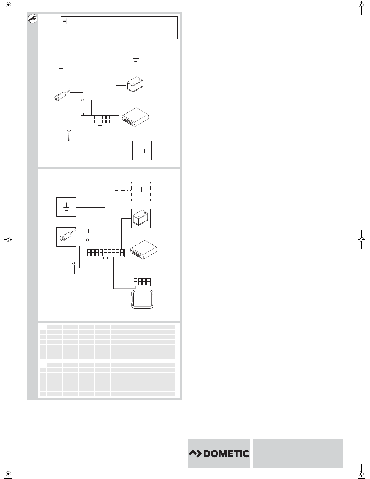
EN DE FR ES PT IT NL DA
bl Blue Blau Bleu Azul Azul Blu Blauw Blå
rt Red Rot Rouge Rojo Ver mel ho Rosso Rood Rø d
sw Black Schwarz Noir Negro Preto Nero Zwart Sort
ws White Weiß Blanc Blanco Branco Bianco Wit Hvid
pk Pink Pink Rosa Rose Cor de rosa Rosa Roze Lyse rød e
gr Grey Grau Gris Gris Cinzento Grigio Grijs Grå
SV NO FI RU PL SK CS HU
bl Blå Blå Sininen Синий Niebieski Modrá Modrá Ké k
rt Röd Rød Punainen Красный Czerwony Červená Červená Piros
sw Svart Svart Musta Черный Czarny Čierna Černá Fekete
ws Vit Hvit Val koi nen Белый Biały Fialová Bílá Fehér
pk Rosa Rosa Pinkki Розовый Różowy Ružová Růžová Rózsaszín
gr Grå Grå Harmaa Серый Szary Sivá Šedá Szürke
EN: 6
DE: 13
FR: 20
ES: 27
PT: 34
IT: 41
NL: 48
DA: 55
SV: 62
NO: 69
FI: 76
RU: 83
PL: 90
SK: 97
CS: 104
HU: 111
4445101745 08/2016
Page 3
ENDEFRESPTITNLDASV
NOFIRUPLSKCSHU
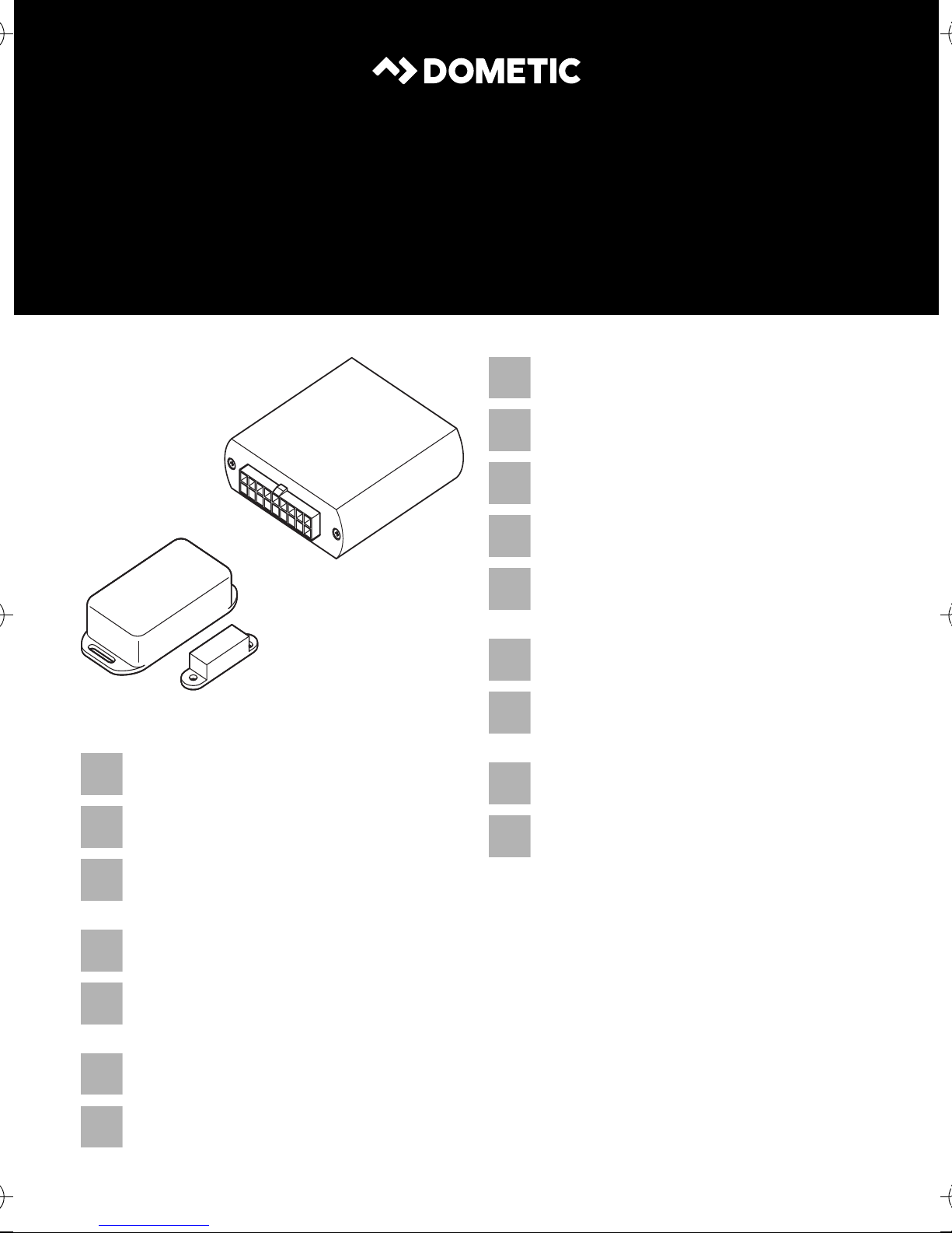
SAFETY SOLUTIONS
MAGICSAFE
Trådløs modtager
Monterings- og betjeningsvejledning . . 52
Trådlös mottagare
Monterings- och bruksanvisning. . . . . . . 59
Trådløs mottaker
Monterings- og bruksanvisning . . . . . . . 66
Langaton vastaanotin
Asennus- ja käyttöohje. . . . . . . . . . . . . . . 73
Радиоприемник
Инструкция по монтажу
и эксплуатации. . . . . . . . . . . . . . . . . . . . . 80
RRC 90
Wireless receiver
Installation and Operating Manual . . . . . . 3
Funk-Empfänger
Montage- und Bedienungsanleitung . . . 10
Récepteur radio
Instructions de montage
et de service . . . . . . . . . . . . . . . . . . . . . . . 17
Receptor RF
Instrucciones de montaje y de uso . . . . . 24
Recetor de radiofrequência
Instruções de montagem e manual de
instruções . . . . . . . . . . . . . . . . . . . . . . . . . 31
Ricevitore radio
Istruzioni di montaggio e d’uso . . . . . . . .38
Odbiornik radiowy
Instrukcja montażu i obsługi . . . . . . . . . . 87
Rádiový prijímač
Návod na montáž a uvedenie
do prevádzky . . . . . . . . . . . . . . . . . . . . . . 94
Rádiový přijímač
Návod k montáži a obsluze . . . . . . . . . . .101
Vezeték nélküli vevő
Szerelési és használati útmutató . . . . . . 108
Radio-ontvanger
Montagehandleiding en
gebruiksaanwijzing. . . . . . . . . . . . . . . . . . 45
Page 4

Page 5

RRC90 Explanation of symbols
EN
Please read this instruction manual carefully before installation and first use, and store
it in a safe place. If you pass on the product to another person, hand over this instruction manual along with it.
Table of contents
1 Explanation of symbols. . . . . . . . . . . . . . . . . . . . . . . . . . . . . . . . . . . . . . . . . . . . . . . . . . . . . . .3
2 Safety and installation instructions . . . . . . . . . . . . . . . . . . . . . . . . . . . . . . . . . . . . . . . . . . . . . .4
3 Scope of delivery . . . . . . . . . . . . . . . . . . . . . . . . . . . . . . . . . . . . . . . . . . . . . . . . . . . . . . . . . . .4
4 Accessories. . . . . . . . . . . . . . . . . . . . . . . . . . . . . . . . . . . . . . . . . . . . . . . . . . . . . . . . . . . . . . . . 4
5 Intended use. . . . . . . . . . . . . . . . . . . . . . . . . . . . . . . . . . . . . . . . . . . . . . . . . . . . . . . . . . . . . . . 4
6 Instructions before installation . . . . . . . . . . . . . . . . . . . . . . . . . . . . . . . . . . . . . . . . . . . . . . . . . 5
7 Installing the wireless magnet contact switch . . . . . . . . . . . . . . . . . . . . . . . . . . . . . . . . . . . . .5
8 Connecting electrical power to the wireless receiver. . . . . . . . . . . . . . . . . . . . . . . . . . . . . . .6
9 Programming the wireless receiver . . . . . . . . . . . . . . . . . . . . . . . . . . . . . . . . . . . . . . . . . . . . . 7
10 Cleaning and caring for the wireless receiver . . . . . . . . . . . . . . . . . . . . . . . . . . . . . . . . . . . . . 8
11 Warranty . . . . . . . . . . . . . . . . . . . . . . . . . . . . . . . . . . . . . . . . . . . . . . . . . . . . . . . . . . . . . . . . . . 9
12 Disposal. . . . . . . . . . . . . . . . . . . . . . . . . . . . . . . . . . . . . . . . . . . . . . . . . . . . . . . . . . . . . . . . . . . 9
13 Technical data. . . . . . . . . . . . . . . . . . . . . . . . . . . . . . . . . . . . . . . . . . . . . . . . . . . . . . . . . . . . . . 9
1 Explanation of symbols
WARNING!
!
!
A
Safety instruction: Failure to observe this instruction can cause fatal or serious injury.
CAUTION!
Safety instruction: Failure to observe this instruction can lead to injury.
NOTICE!
Failure to observe this instruction can cause material damage and impair the function
of the product.
NOTE
I
Supplementary information for operating the product.
3
Page 6

Safety and installation instructions RRC90
EN
2 Safety and installation instructions
See fig. 1
Please observe the prescribed safety instructions and stipulations from the vehicle
manufacturer and service workshops.
The manufacturer accepts no liability for damage in the following cases:
• Damage to the product resulting from mechanical influences and excess voltage
• Alterations to the product without express permission from the manufacturer
• Use for purposes other than those described in the operating manual
3Scope of delivery
See fig. 2
No. in
fig. 2
1 1 Wireless magnetic contact switch 9600000379
21Control unit
3 1 Status LED
4 1 Control unit connection cable
––Fastening material
Quantity Designation Ref. no.
4 Accessories
Available as accessories (not included in the scope of delivery):
Designation Ref. no.
Wireless window contact switch 9600000381
Wireless infrared motion sensor 9600000371
Wireless magnetic contact switch 9600000379
5Intended use
The wireless receiver (ref. no. 9600000378) is supplementary to the DVS90 alarm system
(ref. no. 611900) among others, to ensure the monitoring of roof boxes, caravan stowage
compartments or caravan windows, using wireless magnetic contact switches.
4
Page 7

RRC90 Instructions before installation
EN
6 Instructions before installation
Supplementary to fig. 3
NOTE
I
The wireless receiver is suitable for vehicles with a 12 V power supply.
6.1 Determining the installation location for the receiver control unit
See fig. 4
Select an installation location for the control unit near the control module of the alarm system:
• In the vehicle interior
• Not in areas where strong electrical fields could cause interference, e.g. ignition cables or
central control electronics
If you do not have sufficient technical knowledge for installing and connecting
components in vehicles, you should have a specialist install it for you.
• Not in the immediate vicinity of other control units, to prevent the devices from interfering
with each other (which could cause malfunctions and reduce the range of the radio remote
control)
• Not directly next to ventilator nozzles.
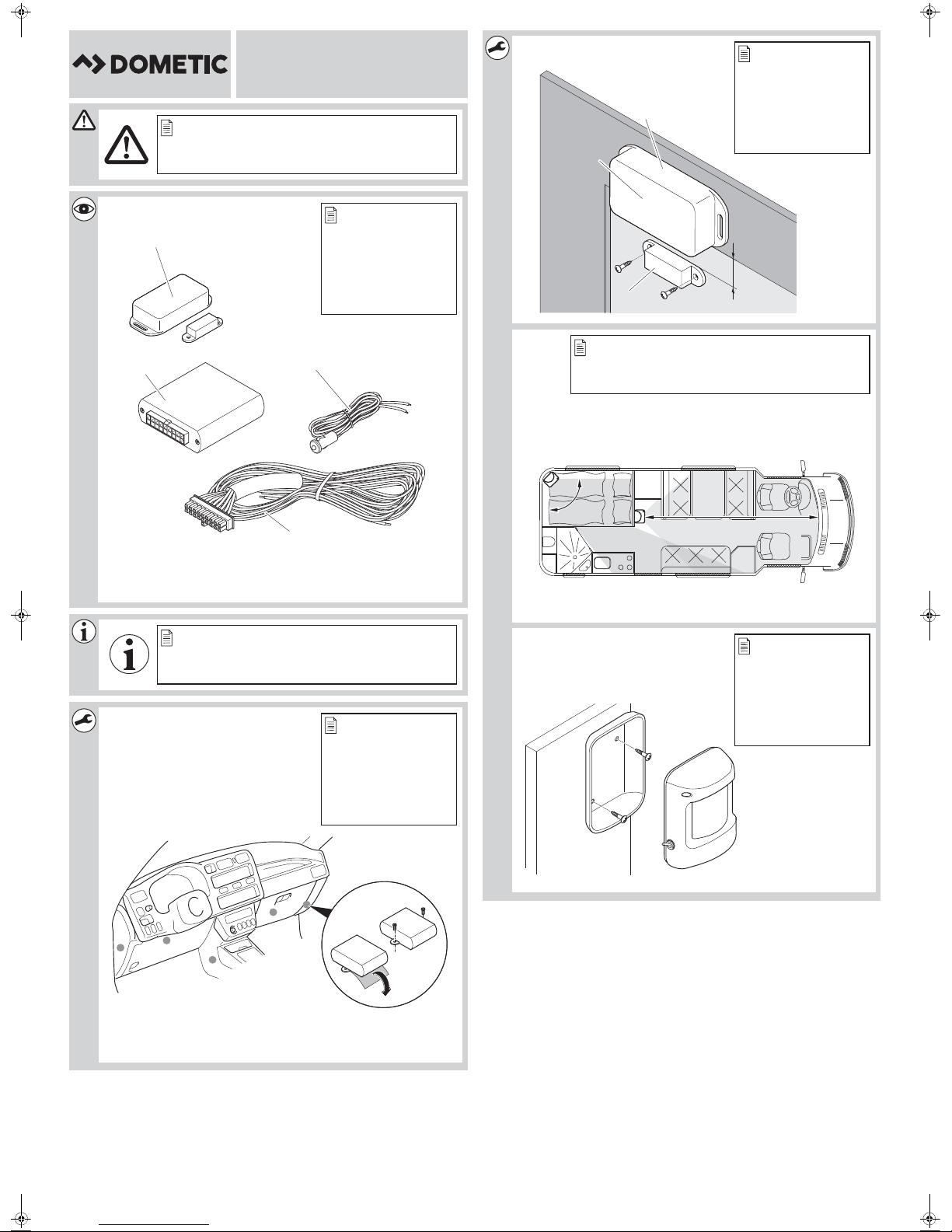
7 Installing the wireless magnet contact switch
See fig. 5
Observe the following installation instructions:
• Install the wireless magnetic contact switch in the interior of the vehicle.
• The interval between the magnet (3) and sensor (1) must not exceed 12 mm.
• Align the sensor so that the LED (2) points away from the magnet (3).
➤ Tightly fasten the magnet (3) to the door, to the stowage compartment lid or to the window.
➤ Screw the sensor (1) to a fixed component (e.g. door or window frame).
➤ Test whether the interval is small enough:
When you open the doors, the LED (2) must light up once briefly.
NOTE
I
For securing windows, use the wireless window contact switch (ref. no. 9600000381).
The wireless window contact switch must be installed on the window frame so that the
contact is pressed down when the window is closed.
5
Page 8

Connecting electrical power to the wireless receiver RRC90
EN
7.1 Installi ng the wi reless motion sensor (accessory)
See fig. 6 and fig. 7
When installing the motion sensor, observe the following instructions:
• Choose an installation location that allows the entire vehicle interior to be monitored (fig. 6).
• The motion sensor can detect movements at a distance of maximum 12 m. It cannot detect
movements behind stationary objects such as partitions. If appropriate, use several motion
sensors.
• Try to avoid blind spots by positioning the sensors well.
• Do not install the motion sensor at a height of more than 2 m above the vehicle floor.
• Do not install the motion sensor close to sources of heat, such as heaters, or outlet nozzles for
warm air.
➤ Press the housing of the motion sensor in slightly on both sides and remove it from the rear
panel (fig. 7).
➤ Screw the rear panel to a suitable installation location.
➤ Put the housing back onto the rear panel and click it into place.
8 Connecting electrical power to the wireless receiver
8.1 Connection cables of the 18-pole plug
See fig. 8 and fig. 9
White/black (P3)
Connect this cable with the black cable of the status LED during the programming procedure.
Connect the red cable from the status LED to +12 V (terminal 30) during the programming
procedure.
Black (P5)
Connect this cable to the earth (terminal 31) or
connect this cable to the earth-controlled cable of the alarm system (e.g. DVS90 alarm system).
Light blue (P7)
Connect the light blue cable to the earth (terminal 31) during the programming procedure, to start
the programming mode.
Red (P9)
Connect this cable to a cable with a permanent +12 V charge (terminal 30).
6
Page 9

RRC90 Programming the wireless receiver
EN
Pink (P16)
Connect this cable to the earth-controlled cable of the alarm system (e.g. DVS90 alarm system).
The P1 socket is for the antenna and does not have to be connected.
➤ Lay the antenna at an interval of at least 1 cm to metallic parts
8.2 Laying cables
When laying the cables, make sure:
• they are not kinked or twisted
• they do not rub on edges
• they are not laid in sharp-edged ducts without protection.
NOTICE!
A
Before drilling any holes, ensure that no electrical cables or other parts of the vehicle
can be damaged by drilling, sawing and filing.
➤ Lay the cable so that they cannot be damaged under any circumstances.
➤ Insulate all unused cable ends.
8.3 Connecting the connection cable to the control unit
➤ Insert the plug of the connection cable into the corresponding connection on the control unit.
✓ When the control unit is connected to the power supply, the red status LED lights up for 20
seconds. Then the LED flashes, which means the device is ready for programming.
9 Programming the wireless receiver
Starting the programming mode
➤ Connect the light blue cable to the earth (terminal 31) to start the programming mode.
✓ The red status LED flashes ten times and then remains lit.
NOTE
I
The red status LED is only needed for the programming procedure and can be
removed at the end.
Programming sensors
➤ Open the door, the stowage compartment lid or the window so that the sensor emits a signal.
✓ The red LED on the sensor lights up briefly.
✓ The red status LED goes out briefly to indicate that the programming was successful.
7
Page 10

Cleaning and caring for the wireless receiver RRC90
EN
Programming the wireless motion sensor (accessory)
➤ Switch the motion sensor on using the switch.
➤ The red status LED on the motion sensor flashes.
✓ The motion sensor has been programmed.
NOTE
I
Ending the programming mode
➤ Disconnect the light blue cable from the earth.
✓ The red status LED lights up for 20 seconds. Then the LED flashes continuously.
➤ Insulate and store the light blue cable.
➤ Remove the red status LED.
You can programme up to 14 sensors (including wireless motion sensor available as an
accessory for the alarm system).
Once the fourteenth sensor has been programmed, the red status LED flashes ten
times.
10 Cleaning and caring for the wireless receiver
NOTICE!
A
Do not use sharp or hard objects to clean the device as these may damage the
components.
8
Page 11
RRC90 Warranty
EN
12
11 Warranty
The statutory warranty period applies. If the product is defective, please contact the
manufacturer's branch in your country (see the back of the instruction manual for the addresses) or
your retailer.
For repair and guarantee processing, please send the following items:
• Defect components
• A copy of the receipt with purchasing date
• A reason for the claim or description of the fault
12 Disposal
➤ Place the packaging material in the appropriate recycling waste bins wherever possible.
If you wish to finally dispose of the product, ask your local recycling centre or specialist
dealer for details about how to do this in accordance with the applicable disposal
M
regulations.
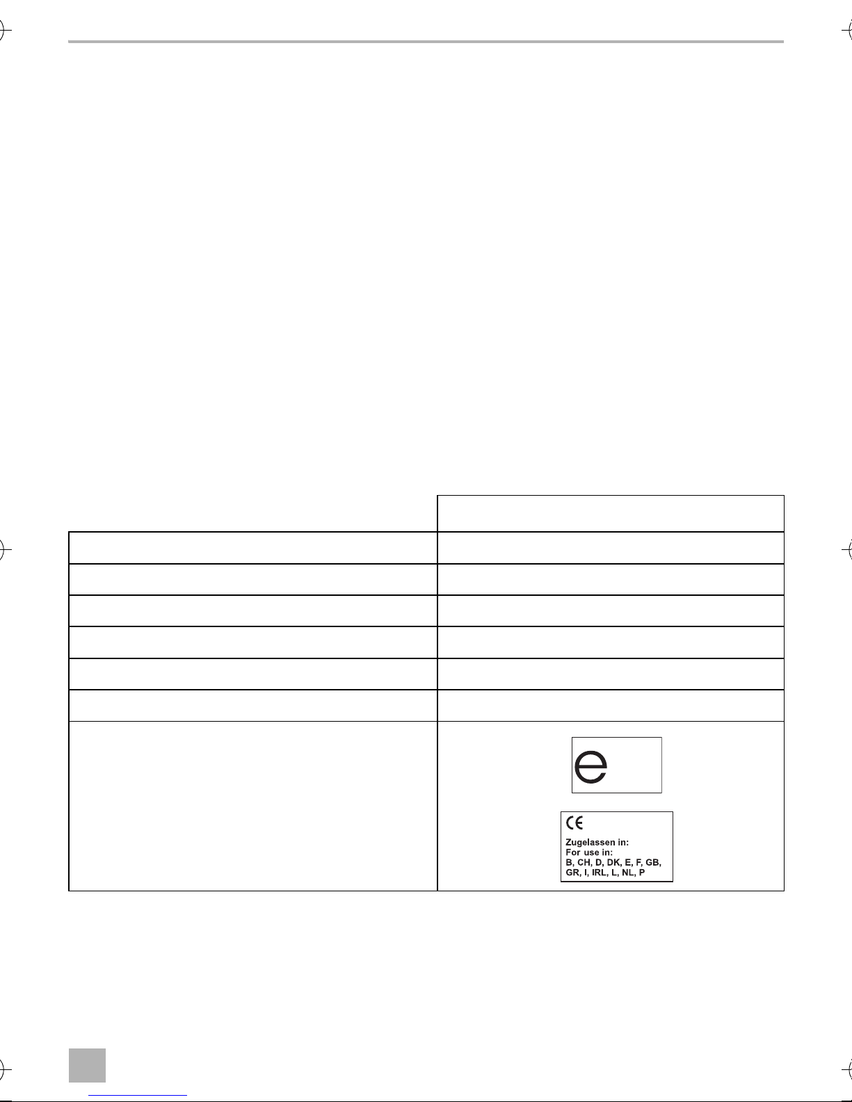
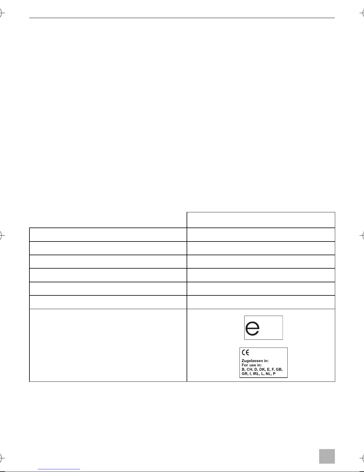
13 Technical data
MagicSafe RRC90
Ref. no.: 9600000378
Operating voltage: 9 – 15 Vg
Power consumption: < 3 mA
Frequency range: 433.92 MHz
Operating temperature: –30 °C to +80 °C
Batteries for wireless magnet contact switch: 3 V CR2032
Certifications:
9
Page 12

Erklärung der Symbole RRC90
DE
Bitte lesen Sie diese Anleitung vor Einbau und Inbetriebnahme sorgfältig durch und
bewahren Sie sie auf. Geben Sie sie im Falle einer Weitergabe des Produktes an den
Nutzer weiter.
Inhaltsverzeichnis
1 Erklärung der Symbole. . . . . . . . . . . . . . . . . . . . . . . . . . . . . . . . . . . . . . . . . . . . . . . . . . . . . . 10
2 Sicherheits- und Einbauhinweise. . . . . . . . . . . . . . . . . . . . . . . . . . . . . . . . . . . . . . . . . . . . . . 11
3 Lieferumfang . . . . . . . . . . . . . . . . . . . . . . . . . . . . . . . . . . . . . . . . . . . . . . . . . . . . . . . . . . . . . . 11
4 Zubehör . . . . . . . . . . . . . . . . . . . . . . . . . . . . . . . . . . . . . . . . . . . . . . . . . . . . . . . . . . . . . . . . . 11
5 Bestimmungsgemäßer Gebrauch . . . . . . . . . . . . . . . . . . . . . . . . . . . . . . . . . . . . . . . . . . . . . 11
6 Hinweise vor dem Einbau . . . . . . . . . . . . . . . . . . . . . . . . . . . . . . . . . . . . . . . . . . . . . . . . . . . 12
7 Funk-Magnetkontaktschalter montieren . . . . . . . . . . . . . . . . . . . . . . . . . . . . . . . . . . . . . . . . 12
8 Funk-Empfänger elektrisch anschließen . . . . . . . . . . . . . . . . . . . . . . . . . . . . . . . . . . . . . . . . 13
9 Funk-Empfänger anlernen . . . . . . . . . . . . . . . . . . . . . . . . . . . . . . . . . . . . . . . . . . . . . . . . . . . 14
10 Funk-Empfänger pflegen und reinigen . . . . . . . . . . . . . . . . . . . . . . . . . . . . . . . . . . . . . . . . . 15
11 Gewährleistung . . . . . . . . . . . . . . . . . . . . . . . . . . . . . . . . . . . . . . . . . . . . . . . . . . . . . . . . . . . 16
12 Entsorgung . . . . . . . . . . . . . . . . . . . . . . . . . . . . . . . . . . . . . . . . . . . . . . . . . . . . . . . . . . . . . . . 16
13 Technische Daten . . . . . . . . . . . . . . . . . . . . . . . . . . . . . . . . . . . . . . . . . . . . . . . . . . . . . . . . . . 16
1 Erklärung der Symbole
WARNUNG!
!
!
A
Sicherheitshinweis: Nichtbeachtung kann zu Tod oder schwerer Verletzung führen.
VORSICHT!
Sicherheitshinweis: Nichtbeachtung kann zu Verletzungen führen.
ACHTUNG!
Nichtbeachtung kann zu Materialschäden führen und die Funktion des Produktes
beeinträchtigen.
HINWEIS
I
10
Ergänzende Informationen zur Bedienung des Produktes.
Page 13

RRC90 Sicherheits- und Einbauhinweise
DE
2 Sicherheits- und Einbauhinweise
Siehe Abb. 1
Beachten Sie die vom Fahrzeughersteller und vom Kfz-Handwerk vorgeschriebenen
Sicherheitshinweise und Auflagen!
Der Hersteller übernimmt in folgenden Fällen keine Haftung für Schäden:
• Beschädigungen am Produkt durch mechanische Einflüsse und Überspannungen
• Veränderungen am Produkt ohne ausdrückliche Genehmigung vom Hersteller
• Verwendung für andere als die in der Anleitung beschriebenen Zwecke
3Lieferumfang
Siehe Abb. 2
Nr. in
Abb. 2
1 1 Funk-Magnetkontaktschalter 9600000379
21Steuergerät
31Status-LED
4 1 Anschlusskabel Steuergerät
––Befestigungsmaterial
Menge Bezeichnung Artikel-Nr.
4Zubehör
Als Zubehör erhältlich (nicht im Lieferumfang enthalten):
Bezeichnung Artikel-Nr.
Funk-Fensterkontaktschalter 9600000381
Funk-Infrarotbewegungsmelder 9600000371
Funk-Magnetkontaktschalter 9600000379
5 Bestimmungsgemäßer Gebrauch
Der Funk-Empfänger (Art.-Nr. 9600000378) ist eine Ergänzung, z. B. zu der Alarmanlage DVS90
(Art.-Nr. 611900), um die Überwachung von z. B. Dachboxen, Wohnmobil-Staufächern oder
Wohnmobilfenstern durch den dazugehörigen Funk-Magnetkontaktschalter zu gewährleisten.
11
Page 14

Hinweise vor dem Einbau RRC90
DE
6 Hinweise vor dem Einbau
Ergänzung zu Abb. 3
HINWEIS
I
Der Funk -Empfänger ist für Fahrzeuge mit einer 12-V-Bordspannung geeignet.
6.1 Einbauort für das Empfänger-Steuergerät festlegen
Siehe Abb. 4
Wählen Sie den Einbauort für das Steuergerät in der Nähe des Steuermoduls der Alarmanlage:
• im Fahrgastinnenraum,
• nicht im Einflussbereich starker elektrischer Felder, z. B. Zündleitungen oder Zentral-
steuerelektronik,
Wenn Sie nicht über ausreichende technische Kenntnisse für das Einbauen und
Anschließen von Komponenten in Fahrzeugen verfügen, sollten Sie den Einbau von
einem Fachmann durchführen lassen.
• nicht direkt neben anderen Steuergeräten, um gegenseitige Störungen der Geräte zu ver-
hindern (dadurch können Fehlfunktionen auftreten, und die Reichweite des Funk-Empfängers
kann vermindert werden)
• nicht direkt an Luftaustrittsdüsen.
7 Funk-Magnetkontaktschalter montieren
Siehe Abb. 5
Beachten Sie folgende Hinweise bei der Montage:
• Montieren Sie den Funk-Magnetkontaktschalter im Inneren des Fahrzeugs.
• Der Abstand zwischen Magnet (3) und Sensor (1) darf nicht mehr als 12 mm betragen.
• Richten Sie den Sensor so aus, dass die LED (2) vom Magneten (3) weg weist.
➤ Schrauben Sie den Magnet (3) an der Tür, an der Staufach-Klappe oder am Fenster fest.
➤ Schrauben Sie den Sensor (1) an den feststehenden Teil (z. B. Tür- oder Fensterrahmen).
➤ Testen Sie, ob der Abstand klein genug ist:
Wenn Sie die Türe öffnen, muss die LED (2) einmal kurz aufleuchten.
HINWEIS
I
Für die Absicherung von Fenstern, sollten Sie den Funk-Fensterkontaktschalter
(Art.-Nr. 9600000381) verwenden. Der Funk-Fensterkontaktschalter muss so am
Fensterrahmen montiert werden, dass der Kontakt bei geschlossenem Fenster
gedrückt wird.
12
Page 15

RRC90 Funk-Empfänger elektrisch anschließen
DE
7.1 Funk-Bewegungsmelder (Zubehör) montieren
Siehe Abb. 6 und Abb. 7
Beachten Sie folgende Hinweise bei der Montage des Bewegungsmelders:
• Wählen Sie den Montageort so, dass der Fahrzeuginnenraum komplett überwacht wird
(Abb. 6).
• Der Bewegungsmelder kann Bewegungen in einer Entfernung von maximal 12 m erkennen. Er
kann keine Bewegungen hinter festen Gegenständen wie z. B. Zwischenwänden erkennen.
Verwenden Sie ggf. mehrere Bewegungsmelder.
• Versuchen Sie durch gute Positionierung, tote Winkel zu vermeiden.
• Montieren Sie den Bewegungsmelder nicht höher als 2 m über dem Boden des Fahrzeugs.
• Montieren Sie den Bewegungsmelder nicht in der Nähe von Wärmequellen wie z. B. Heiz-
geräten, oder Warmluftaustrittsdüsen.
➤ Drücken Sie das Gehäuse des Bewegungsmelders auf beiden Seiten leicht ein und nehmen
Sie es von der Rückwand ab (Abb. 7).
➤ Schrauben Sie die Rückwand an einen geeigneten Montageort.
➤ Setzen Sie das Gehäuse wieder auf die Rückwand und rasten Sie es ein.
8 Funk-Empfänger elektrisch anschließen
8.1 Anschlussleitungen des 18-poligen Steckers
Siehe Abb. 8 und Abb. 9
Weiß/Schwarz (P3)
Verbinden Sie diese Leitung während des Anlernvorgangs mit der schwarzen Leitung der StatusLED. Schließen Sie die rote Leitung der Status-LED während des Anlernvorgangs an +12 V
(Klemme 30) an.
Schwarz (P5)
Schließen Sie diese Leitung an Masse an (Klemme 31) oder
schließen Sie diese Leitung an den massegesteuerten Eingang der Alarmanlage an (z. B. Alarmanlage DVS90).
Hellblau (P7)
Schließen Sie die hellblaue Leitung für die Dauer des Anlernvorgangs an Masse an (Klemme 31),
um den Anlernmodus zu starten.
Rot (P9)
Schließen Sie diese Leitung an eine permanent +12 V führende Leitung an (Klemme 30).
13
Page 16

Funk-Empfänger anlernen RRC90
DE
Pink (P16)
Schließen Sie diese Leitung an den massegesteuerten Eingang der Alarmanlage an (z. B. Alarmanlage DVS90).
Der Steckplatz P1 ist für die Antenne vorgesehen und muss nicht angeschlossen werden.
➤ Verlegen Sie die Antenne in einem Abstand von mindestens 1 cm zu metallischen Teilen.
8.2 Kabel verlegen
Beachten Sie beim Verlegen der Kabel, dass diese
• nicht stark geknickt oder verdreht werden,
• nicht an Kanten scheuern,
• nicht ohne Schutz durch scharfkantige Durchführungen verlegt werden.
ACHTUNG!
A
Bevor Sie irgendwelche Bohrungen vornehmen, stellen Sie sicher, dass keine
elektrischen Kabel oder andere Teile des Fahrzeuges durch Bohren, Sägen und Feilen
beschädigt werden.
➤ Verlegen Sie die Kabel so, dass sie unter keinen Umständen beschädigt werden können.
➤ Isolieren Sie alle nicht benutzten Kabelenden.
8.3 Anschlusskabel an Steuergerät anschließen
➤ Stecken Sie die Stecker des Anschlusskabels auf die entsprechenden Anschlüsse am Steuer-
gerät.
✓ Wenn das Steuergerät an die Stromversorgung angeschlossen ist, leuchtet die rote Status-LED
für 20 Sekunden. Danach blinkt die LED und zeigt damit an, dass das Gerät bereit für den
Anlernvorgang ist.
9 Funk-Empfänger anlernen
Anlernmodus starten
➤ Schließen Sie die hellblaue Leitung an Masse an (Klemme 31), um den Anlernmodus zu starten.
✓ Die rote Status-LED blinkt zehnmal und leuchtet danach ständig.
HINWEIS
I
Die rote Status-LED wird nur für den Anlernvorgang benötigt und kann am Ende
entfernt werden.
14
Page 17

RRC90 Funk-Empfänger pflegen und reinigen
DE
Sensoren anlernen
➤ Öffnen Sie die Tür, die Staufach-Klappe oder das Fenster, damit der Sensor eine Meldung
abgibt.
✓ Die rote LED am Sensor leuchtet kurz auf.
✓ Die rote Status-LED erlischt kurz, um anzuzeigen, dass der Anlernvorgang erfolgreich war.
Funk-Bewegungsmelder (Zubehör) anlernen
➤ Schalten Sie den Bewegungsmelder mit dem Schalter ein.
➤ Die rote Status-LED am Bewegungsmelder blinkt.
✓ Der Bewegungsmelder ist angelernt.
HINWEIS
I
Anlernmodus beenden
Sie können maximal 14 Sensoren (auch Funk-Bewegungsmelder, als Zubehör zu
Alarmanlage erhältlich) anlernen.
Nachdem der vierzehnte Sensor angelernt wurde, blinkt die rote Status-LED zehnmal.
➤ Trennen Sie die hellblaue Leitung von der Masse.
✓ Die rote Status-LED leuchtet 20 Sekunden. Danach blinkt die LED ständig.
➤ Isolieren und verstauen Sie die hellblaue Leitung.
➤ Entfernen Sie die rote Status-LED.
10 Funk-Empfänger pflegen und reinigen
ACHTUNG!
A
Keine scharfen oder harten Mittel zur Reinigung verwenden, da dies zu einer
Beschädigung der Komponenten führen kann.
15
Page 18
Gewährleistung RRC90
DE
12
11 Gewährleistung
Es gilt die gesetzliche Gewährleistungsfrist. Sollte das Produkt defekt sein, wenden Sie sich bitte
an die Niederlassung des Herstellers in Ihrem Land (Adressen siehe Rückseite der Anleitung) oder
an Ihren Fachhändler.
Zur Reparatur- bzw. Gewährleistungsbearbeitung müssen Sie Folgendes einschicken:
• defekte Komponenten,
• eine Kopie der Rechnung mit Kaufdatum,
• einen Reklamationsgrund oder eine Fehlerbeschreibung.
12 Entsorgung
➤ Geben Sie das Verpackungsmaterial möglichst in den entsprechenden Recycling-Müll.
Wenn Sie das Produkt endgültig außer Betrieb nehmen, informieren Sie sich bitte beim
nächsten Recyclingcenter oder bei Ihrem Fachhändler über die zutreffenden
M
Entsorgungsvorschriften.
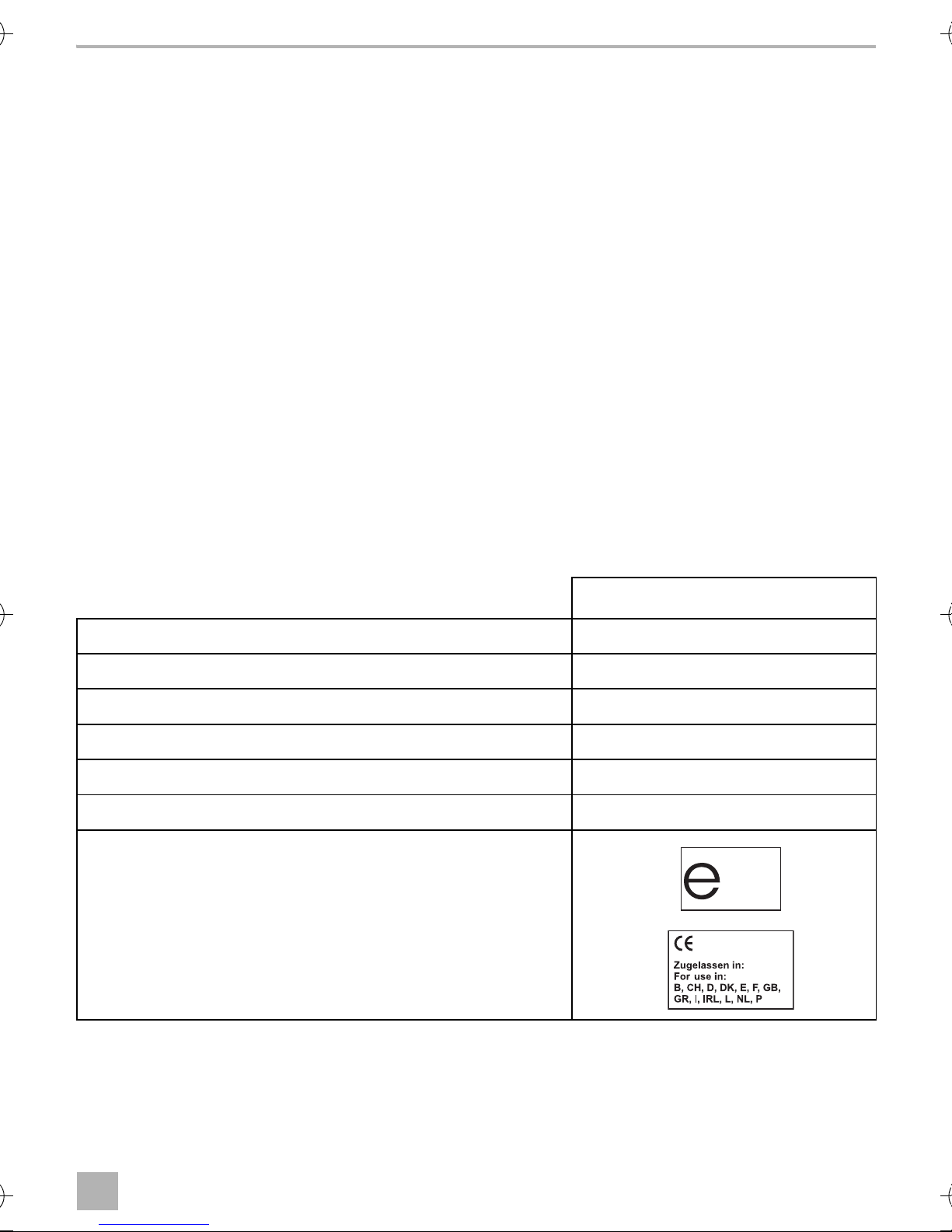
13 Technische Daten
MagicSafe RRC90
Art.-Nr.: 9600000378
Betriebsspannung: 9 – 15 Vg
Stromaufnahme: < 3 mA
Frequenzbereich: 433,92 MHz
Betriebstemperatur: –30 °C bis +80 °C
Batterien für Funk-Magnetkontaktschalter: 3 V CR2032
Zulassungen:
16
Page 19

RRC90 Explication des symboles
FR
Veuillez lire attentivement cette notice avant le montage et la mise en service. Veuillez
ensuite la conserver. En cas de passer le produit, veuillez le transmettre au nouvel
acquéreur.
Table des matières
1 Explication des symboles. . . . . . . . . . . . . . . . . . . . . . . . . . . . . . . . . . . . . . . . . . . . . . . . . . . . 17
2 Consignes de sécurité et instructions de montage. . . . . . . . . . . . . . . . . . . . . . . . . . . . . . . . 18
3 Contenu de la livraison. . . . . . . . . . . . . . . . . . . . . . . . . . . . . . . . . . . . . . . . . . . . . . . . . . . . . . 18
4 Accessoires. . . . . . . . . . . . . . . . . . . . . . . . . . . . . . . . . . . . . . . . . . . . . . . . . . . . . . . . . . . . . . . 18
5 Usage conforme . . . . . . . . . . . . . . . . . . . . . . . . . . . . . . . . . . . . . . . . . . . . . . . . . . . . . . . . . . . 18
6 Consignes préalables au montage . . . . . . . . . . . . . . . . . . . . . . . . . . . . . . . . . . . . . . . . . . . . 19
7 Montage du commutateur magnétique radio. . . . . . . . . . . . . . . . . . . . . . . . . . . . . . . . . . . . 19
8 Raccordement électrique du récepteur radio. . . . . . . . . . . . . . . . . . . . . . . . . . . . . . . . . . . .20
9 Apprentissage du récepteur radio. . . . . . . . . . . . . . . . . . . . . . . . . . . . . . . . . . . . . . . . . . . . .22
10 Entretien et nettoyage du récepteur radio . . . . . . . . . . . . . . . . . . . . . . . . . . . . . . . . . . . . . .22
11 Garantie. . . . . . . . . . . . . . . . . . . . . . . . . . . . . . . . . . . . . . . . . . . . . . . . . . . . . . . . . . . . . . . . . .23
12 Retraitement . . . . . . . . . . . . . . . . . . . . . . . . . . . . . . . . . . . . . . . . . . . . . . . . . . . . . . . . . . . . . .23
13 Caractéristiques techniques. . . . . . . . . . . . . . . . . . . . . . . . . . . . . . . . . . . . . . . . . . . . . . . . . .23
1 Explication des symboles
AVERTISSEMENT !
!
!
Consigne de sécurité : le non-respect de ces consignes peut entraîner la mort ou de
graves blessures.
ATTENTION !
Consigne de sécurité : le non-respect de ces consignes peut entraîner des bles-
sures.
AVIS !
A
I
Le non-respect de ces consignes peut entraîner des dommages matériels et des
dysfonctionnements du produit.
REMARQUE
Informations complémentaires sur l'utilisation du produit.
17
Page 20
Consignes de sécurité et instructions de montage RRC90
FR
2 Consignes de sécurité et instructions de montage
Voir fig. 1
Respectez les consignes de sécurité et autres prescriptions imposées par le fabricant
du véhicule et par les professionnels de l'automobile !
Le fabricant décline toute responsabilité pour des dommages dans les cas suivants :
• des influences mécaniques et des surtensions ayant endommagé le matériel
• des modifications apportées au produit sans autorisation explicite de la part du fabricant
• une utilisation différente de celle décrite dans la notice
3 Contenu de la livraison
Voir fig. 2
N° dans
fig. 2
1 1 Commutateur magnétique radio 9600000379
2 1 Unité de commande
31Voyant d'état
4 1 Câble de raccordement de l'unité de commande
– – Matériel de fixation
Quantité Désignation N° d'article
4 Accessoires
Disponibles en accessoires (non compris dans la livraison) :
Désignation N° d'article
Commutateur des vitres radio 9600000381
Détecteur de mouvement infrarouge radio 9600000371
Commutateur magnétique radio 9600000379
5Usage conforme
Le récepteur radio (n° d'article 9600000378) complète par exemple le système d’alarme DVS90
(n° d'article 611900), afin de garantir la surveillance par ex. des galeries de toit, des espaces de
rangement ou des fenêtres des camping-cars grâce au commutateur magnétique radio
correspondant.
18
Page 21

RRC90 Consignes préalables au montage
FR
6 Consignes préalables au montage
Complément de la fig. 3
REMARQUE
I
Le récepteur radio convient pour les véhicules avec une tension de bord de 12 V.
6.1 Détermination de l'emplacement de montage de l'unité de
Voir fig. 4
Choisissez un emplacement de montage de l'unité à proximité du module de commande du
système d’alarme :
• à l'intérieur du véhicule
Si vos connaissances techniques en matière d'installation et de raccordement
d'éléments dans un véhicule sont insuffisantes, nous vous recommandons de confier
l'installation à un spécialiste.
commande du récepteur
• en dehors de l'influence de champs électriques, par ex. circuits d'allumage ou électronique
de commande centrale
• pas à proximité directe d'autres unités de commande afin d'éviter des interférences entre
les appareils (ceci pourrait provoquer des dysfonctionnements et réduire la portée du
récepteur radio)
• pas directement devant les buses de sortie d'air.
7 Montage du commutateur magnétique radio
Voir fig. 5
Veuillez respecter les consignes suivantes lors du montage :
• Montez le commutateur magnétique radio à l'intérieur du véhicule.
• La distance entre l'aimant (3) et le détecteur (1) ne doit pas être supérieure à 12 mm.
• Orientez le détecteur de telle sorte que la LED (2) soit inversée par rapport à
l'aimant (3).
➤ Vissez l'aimant (3) à la portière, à la trappe du compartiment de rangement ou à la vitre.
➤ Vissez le détecteur (1) à la partie fixe (par ex. le cadre de la portière ou de la vitre).
➤ Vérifiez si la distance est assez courte :
La LED (2) doit s'allumer brièvement lorsque vous ouvrez les portières.
19
Page 22

Raccordement électrique du récepteur radio RRC90
FR
REMARQUE
I
Pour protéger les vitres, veuillez utiliser le commutateur des vitres radio
(n° d'article 9600000381). Le commutateur des vitres radio doit être monté sur le
cadre de la vitre de manière à ce que le contact soit enfoncé lorsque la fenêtre est
fermée.
7.1 Montage du détecteur de mouvement radio (accessoires)
Voir fig. 6 et fig. 7
Tenez compte des remarques suivantes lors du montage du détecteur de mouvement :
• Sélectionnez le lieu de montage de telle sorte que tout l'habitacle du véhicule soit surveillé
(fig. 6).
• Le détecteur de mouvement peut détecter des mouvements à une distance maximale de 12 m.
Il ne peut détecter de mouvement derrière des objets fixes comme par ex. des parois
intermédiaires. Utilisez plusieurs détecteurs si nécessaire.
• Essayez d'éviter les angles morts en positionnant bien les détecteurs.
• Ne montez pas le détecteur de mouvement à une hauteur supérieure à 2 m au-dessus du
plancher du véhicule.
• Ne montez pas le détecteur de mouvement à proximité de sources de chaleur telles que des
radiateurs ou des buses de sortie d'air chaud.
➤ Appuyez légèrement sur les côtés du bâti du détecteur de mouvement et retirez-le de la paroi
arrière (fig. 7).
➤ Vissez la paroi arrière à un emplacement adéquat.
➤ Replacez le bâti sur la paroi arrière et faites-le s'enclencher dedans.
8 Raccordement électrique du récepteur radio
8.1 Câbles de raccordement du connecteur à 18 pôles
Voir fig. 8 et fig. 9
Blanc/noir (P3)
Raccordez ce câble pendant le processus d'apprentissage au câble noir de la LED d'état.
Branchez le câble rouge de la LED d'état pendant le processus d'apprentissage à une source
d'alimentation 12 V (borne 30).
Noir (P5)
Raccordez ce câble à la masse (borne 31) ou
raccordez ce câble à l'entrée à commande par la masse du système d’alarme (par ex. dans le cas
du système d'alarme DVS90).
20
Page 23

RRC90 Raccordement électrique du récepteur radio
FR
Bleu clair (P7)
Raccordez le câble bleu clair à la masse (borne 31) pour la durée du processus d'apprentissage afin
de démarrer le mode d'apprentissage.
Rouge (P9)
Raccordez ce câble à un câble d'alimentation permanente de + 12 V (borne 30).
Rosa (P16)
Raccordez ce câble à l'entrée à commande par la masse du système d’alarme (par ex. dans le cas
du système d'alarme DVS90).
L'emplacement P1 est prévu pour l'antenne et n'a pas besoin d'être raccordé.
➤ Posez l'antenne à une distance d'au moins 1 cm des pièces métalliques
8.2 Pose des câbles
Lors de la pose des câbles, veillez à ce que ceux-ci
• ne soient ni fortement pliés, ni tordus,
• ne frottent pas contre des arêtes,
• ne soient pas placés dans des traversées à arêtes vives sans protection.
AVIS !
A
➤ Posez les câbles de manière à ce qu'ils ne puissent en aucun cas être endommagés.
➤ Isolez toutes les extrémités de câble non utilisées.
Avant de commencer à percer, assurez-vous qu’aucun câble électrique ou autre
élément du véhicule ne risque d’être endommagé par le perçage, le sciage ou le
limage.
8.3 Raccordement du câble de raccordement à l'unité de commande
➤ Raccordez les connecteurs du câble de raccordement aux raccords correspondants de l'unité
de commande.
✓ Si l'unité de commande est raccordée à l'alimentation électrique, la LED d'état rouge s'allume
pendant 20 secondes. Ensuite, la LED clignote, indiquant que l'appareil est prêt pour le
processus d'apprentissage.
21
Page 24

Apprentissage du récepteur radio RRC90
FR
9 Apprentissage du récepteur radio
Démarrage du mode apprentissage
➤ Raccordez le câble bleu clair à la masse (borne 31) pour démarrer le mode d'apprentissage.
✓ La LED d'état rouge clignote 10 fois, puis s'allume en continu.
REMARQUE
I
Apprentissage des détecteurs
➤ Ouvrez la portière, la trappe du compartiment de rangement ou la vitre afin que le détecteur
émette un message.
✓ La LED rouge du détecteur s'allume brièvement.
✓ La LED d'état rouge s'éteint brièvement pour indiquer que la procédure d'apprentissage a
réussie.
La LED d'état rouge sert uniquement au processus d'apprentissage et peut être retirée
à la fin.
Apprentissage des détecteurs de mouvement radio (accessoires)
➤ Mettez le détecteur de mouvement en marche à l'aide du commutateur.
➤ La LED d'état rouge du détecteur de mouvement clignote.
✓ L'apprentissage du détecteur de mouvement est terminé.
REMARQUE
I
Arrêt du mode apprentissage
➤ Débranchez le câble bleu clair de la masse.
✓ La LED d'état rouge s'allume pendant 20 secondes. La LED clignote ensuite en permanence.
➤ Isolez et rangez le câble bleu clair.
➤ Retirez la LED d'état rouge.
Vous pouvez soumettre maximum 14 détecteurs (y compris les détecteurs de
mouvement, disponibles comme accessoires du système d’alarme) à un
apprentissage.
Après que le quatorzième détecteur ait été soumis à l'apprentissage, la LED d'état
rouge clignote 10 fois.
10 Entretien et nettoyage du récepteur radio
AVIS !
A
22
N’utilisez aucun objet coupant ou dur pour le nettoyage. Ceci pourrait endommager
des composants.
Page 25
RRC90 Garantie
FR
12
11 Garantie
Le délai légal de garantie s'applique. Si le produit s'avérait défectueux, veuillez vous adresser à la
filiale du fabricant située dans votre pays (voir adresses au verso du présent manuel) ou à votre
revendeur spécialisé.
Pour toute réparation ou autre prestation de garantie, veuillez joindre à l'appareil les documents
suivants :
• composants défectueux,
• une copie de la facture avec la date d'achat,
• le motif de la réclamation ou une description du dysfonctionnement.
12 Retraitement
➤ Jetez les emballages dans les conteneurs de déchets recyclables prévus à cet effet.
Lorsque vous mettrez votre produit définitivement hors service, informez-vous auprès
du centre de recyclage le plus proche ou auprès de votre revendeur spécialisé sur les
M
prescriptions relatives au retraitement des déchets.
13 Caractéristiques techniques
MagicSafe RRC90
N° de produit : 9600000378
Tension de service : 9 – 15 Vg
Intensité absorbée : < 3 mA
Gamme de fréquence : 433,92 MHz
Température de fonctionnement : –30 °C à +80 °C
Piles pour le commutateur magnétique radio : 3 V CR2032
Certifications :
23
Page 26

Explicación de los símbolos RRC90
ES
Lea detenidamente estas instrucciones antes de llevar a cabo la instalación y puesta en
funcionamiento, y consérvelas en un lugar seguro. En caso de vender o entregar el producto a otra persona, entregue también estas instrucciones.
Índice
1 Explicación de los símbolos. . . . . . . . . . . . . . . . . . . . . . . . . . . . . . . . . . . . . . . . . . . . . . . . . .24
2 Indicaciones sobre seguridad y montaje. . . . . . . . . . . . . . . . . . . . . . . . . . . . . . . . . . . . . . . .25
3 Volumen de entrega. . . . . . . . . . . . . . . . . . . . . . . . . . . . . . . . . . . . . . . . . . . . . . . . . . . . . . . .25
4 Accesorios . . . . . . . . . . . . . . . . . . . . . . . . . . . . . . . . . . . . . . . . . . . . . . . . . . . . . . . . . . . . . . .25
5 Uso adecuado. . . . . . . . . . . . . . . . . . . . . . . . . . . . . . . . . . . . . . . . . . . . . . . . . . . . . . . . . . . . .25
6 Indicaciones previas al montaje. . . . . . . . . . . . . . . . . . . . . . . . . . . . . . . . . . . . . . . . . . . . . . .26
7 Montaje del interruptor de contacto magnético. . . . . . . . . . . . . . . . . . . . . . . . . . . . . . . . . .26
8 Conexión eléctrica del receptor RF . . . . . . . . . . . . . . . . . . . . . . . . . . . . . . . . . . . . . . . . . . . .27
9 Programar el receptor RF . . . . . . . . . . . . . . . . . . . . . . . . . . . . . . . . . . . . . . . . . . . . . . . . . . . .28
10 Mantenimiento y limpieza del receptor RF . . . . . . . . . . . . . . . . . . . . . . . . . . . . . . . . . . . . . .29
11 Garantía legal . . . . . . . . . . . . . . . . . . . . . . . . . . . . . . . . . . . . . . . . . . . . . . . . . . . . . . . . . . . . .30
12 Gestión de residuos . . . . . . . . . . . . . . . . . . . . . . . . . . . . . . . . . . . . . . . . . . . . . . . . . . . . . . . .30
13 Datos técnicos . . . . . . . . . . . . . . . . . . . . . . . . . . . . . . . . . . . . . . . . . . . . . . . . . . . . . . . . . . . .30
1 Explicación de los símbolos
¡ADVERTENCIA!
!
!
A
Indicación de seguridad: su incumplimiento puede acarrear la muerte o graves
lesiones.
¡ATENCIÓN!
Indicación de seguridad: su incumplimiento puede acarrear lesiones.
¡AVISO!
Su incumplimiento puede acarrear daños materiales y perjudicar el correcto funcionamiento del producto.
NOTA
I
24
Información adicional para el manejo del producto.
Page 27
RRC90 Indicaciones sobre seguridad y montaje
ES
2 Indicaciones sobre seguridad y montaje
Véase fig. 1
Tenga en cuenta las indicaciones de seguridad y la documentación suministrada por el
fabricante y el taller del vehículo.
El fabricante declina toda responsabilidad ante daños ocurridos en los siguientes casos:
• daños en el producto debido a influencias mecánicas y sobretensiones
• modificaciones realizadas en el producto sin el expreso consentimiento del fabricante
• utilización del aparato para fines distintos a los descritos en las instrucciones
3 Volumen de entrega
Véase fig. 2
N.º en
fig. 2
1 1 Interruptor de contacto magnético RF 9600000379
21Dispositivo de control
3 1 LED de estado
4 1 Cable de conexión del dispositivo de control
––Material de fijación
Cantidad Denominación N.° de artículo
4 Accesorios
Disponibles como accesorios (no incluidos en el volumen de entrega):
Denominación N.° de artículo
Interruptor de contacto magnético RF 9600000381
Detector de movimiento RF por infrarrojos 9600000371
Interruptor de contacto magnético RF 9600000379
5Uso adecuado
El receptor RF (n.° de art. 9600000378) es un complemento para, por ejemplo, el sistema de
alarma DVS90 (n.° de art. 611900) para garantizar el monitoreo, por ejemplo, de cajas
portaequipajes o ventanas de autocaravanas a través del interruptor de contacto magnético RF.
25
Page 28

Indicaciones previas al montaje RRC90
ES
6 Indicaciones previas al montaje
Complementa la fig. 3
NOTA
I
El receptor RF resulta adecuado para vehículos con una tensión de a bordo de 12 V.
6.1 Determinar el lugar de montaje del dispositivo de control del
Véase fig. 4
El dispositivo de control se debe montar cerca del módulo de control del sistema de alarma:
• en el interior del vehículo;
Si no dispone de conocimientos técnicos suficientes para llevar a cabo el montaje y las
conexiones de componentes en el vehículo, debería solicitar el montaje a personal
técnico cualificado.
receptor
• fuera del radio de acción de campos eléctricos fuertes como, por ejemplo, cables del sistema
de encendido o el sistema electrónico del control central;
• no directamente junto a otros dispositivos de control, para evitar interferencias entre ellos
(que pueden producir un funcionamiento incorrecto y reducir el alcance del receptor RF);
• no directamente en las toberas de salida de aire.
7 Montaje del interruptor de contacto magnético
Véase fig. 5
Tenga en cuenta las siguientes indicaciones durante el montaje:
• Monte el interruptor de contacto magnético RF en el interior del vehículo.
• La distancia entre el imán (3) y el sensor (1) no deberá superar los 12 mm.
• Alinee el sensor de tal manera que el LED (2) quede alejado del imán (3).
➤ Atornille el imán (3) a la puerta, a la tapa del compartimento portaobjetos o a la ventana.
➤ Atornille el sensor (1) a la parte fija (por ejemplo, al marco de la puerta o de la ventana).
➤ Compruebe si la distancia es lo suficientemente pequeña:
al abrir las puertas se debe iluminar brevemente el LED (2).
NOTA
I
26
Para asegurar las ventanas se debe utilizar el interruptor de contacto RF para ventanas
(n.° de art. 9600000381). Este interruptor se debe montar en el marco de la ventana
de tal forma que el contacto quede oprimido cuando la ventana está cerrada.
Page 29

RRC90 Conexión eléctrica del receptor RF
ES
7.1 Montar el detector de movimiento RF (accesorio)
Véase la fig. 6 y la fig. 7.
Al montar el detector de movimiento tenga en cuenta las siguientes indicaciones:
• Elija el lugar de montaje de tal forma que se pueda vigilar todo el interior del vehículo (fig. 6).
• El detector puede detectar movimientos a una distancia máxima de 12 m. No puede detectar
movimientos que se produzcan detrás de objetos fijos como, por ejemplo, paredes
intermedias. En caso necesario, utilice varios detectores de movimiento.
• Intente evitar ángulos muertos mediante un buen posicionamiento.
• No monte el detector de movimiento a más de 2 m por encima del suelo del vehículo.
• No monte el detector de movimiento en las cercanías de fuentes de calor como, por ejemplo,
radiadores o toberas de salida de aire caliente.
➤ Presione ligeramente la carcasa del detector de movimiento a ambos lados y retírela de la
pared posterior (fig. 7).
➤ Atornille la pared trasera a un lugar de montaje adecuado.
➤ Vuelva a colocar la carcasa en la pared trasera y encájela.
8 Conexión eléctrica del receptor RF
8.1 Cables de conexión de la clavija de 18 polos
Véase la fig. 8 y la fig. 9.
Blanco/negro (P3)
Una este cable al cable negro del LED de estado durante el proceso de programación. Conecte el
cable rojo del LED de estado durante el proceso de programación al borne 30 de 12 V.
Negro (P5)
Conecte este cable a masa (borne 31) o bien
conecte este cable a la entrada del sistema de alarma controlada por masa (por ejemplo, sistema
de alarma DVS 90).
Azul claro (P7)
Conecte a masa el cable azul claro durante el proceso de programación (borne 31) para iniciar el
modo de programación.
Rojo (P9)
Conecte este hilo a un cable conductor permanente de +12 V (borne 30).
27
Page 30

Programar el receptor RF RRC90
ES
Rose (P16)
Conecte este cable a la entrada del sistema de alarma controlada por masa (por ejemplo, sistema
de alarma DVS 90).
La conexión P1 está prevista para la antena y no es necesario conectarla.
➤ Coloque la antena a una distancia de por lo menos 1 cm respecto a piezas metálicas.
8.2 Tendido de cables
Al tender los cables asegúrese de que:
• no se doblen ni se retuerzan,
• no rocen con bordes,
• no se tiendan sin protección a través de guías con aristas afiladas.
¡AVISO!
A
Antes de realizar cualquier perforación, asegúrese de que ningún cable eléctrico ni
ninguna otra pieza del vehículo puedan resultar dañados al taladrar, serrar o limar.
➤ Tienda los cables de tal modo que bajo ninguna circunstancia puedan resultar dañados.
➤ Aísle todos los extremos de cable que no se utilicen.
8.3 Conectar el cable de conexión al dispositivo de control
➤ Conecte las clavijas del cable de conexión a las conexiones correspondientes del dispositivo
de control.
✓ Si el dispositivo de control está conectado a la alimentación de corriente, el LED de estado
rojo se ilumina durante 20 segundos. A continuación comienza a parpadear el LED para
indicar que el aparato está listo para la programación.
9 Programar el receptor RF
Iniciar el modo de programación
➤ Conecte a masa el cable azul claro (borne 31) para iniciar el modo de programación.
✓ El LED rojo de estado parpadea 10 veces y, a continuación, se queda iluminado.
NOTA
I
El LED rojo de estado se necesita solo para el proceso de programación y se puede
retirar una vez finalizado dicho proceso.
28
Page 31

RRC90 Mantenimiento y limpieza del receptor RF
ES
Programar los sensores
➤ Abra la puerta, la tapa del compartimento portaobjetos o la ventana para que el sensor emita
un mensaje.
✓ El LED rojo del sensor se ilumina brevemente.
✓ El LED de estado rojo se apaga brevemente para indicar que el proceso de programación ha
finalizado satisfactoriamente.
Programar el detector de movimiento por radio (accesorio)
➤ Active el detector de movimiento de radio con el interruptor.
➤ El LED de estado rojo del detector de movimiento parpadea.
✓ El detector de movimiento está programado.
NOTA
I
Se puede programar un máximo de 14 sensores (también detectores de movimiento
RF adquiribles como accesorio para sistema de alarma).
Una vez programado el decimocuarto sensor parpadea diez veces el LED rojo de
estado.
Finalizar el modo de programación
➤ Desconecte el cable azul claro de masa.
✓ El LED de estado rojo se ilumina durante 20 segundos y, a continuación, se queda
permanentemente iluminado.
➤ Aísle el cable azul claro y colóquelo de forma que quede recogido.
➤ Retire el LED de estado rojo.
10 Mantenimiento y limpieza del receptor RF
¡AVISO!
A
No utilice ningún utensilio de limpieza afilado o duro, ya que podría dañar los
componentes.
29
Page 32

Garantía legal RRC90
ES
12
11 Garantía legal
Rige el plazo de garantía legal. Si el producto presenta algún defecto, diríjase a la sucursal del
fabricante de su país (ver direcciones en el dorso de estas instrucciones) o a su establecimiento
especializado.
Para la tramitación de la reparación y de la garantía debe enviar lo siguiente:
• componentes defectuosos,
• una copia de la factura con fecha de compra,
• el motivo de la reclamación o una descripción de la avería.
12 Gestión de residuos
➤ Deseche el material de embalaje en el contenedor de reciclaje correspondiente.
Cuando vaya a desechar definitivamente el producto, infórmese en el centro de
reciclaje más cercano o en un comercio especializado sobre las normas pertinentes de
M
eliminación de materiales.
13 Datos técnicos
MagicSafe RRC90
N.° art.: 9600000378
Tensión de funcionamiento: 9 – 15 Vg
Consumo de corriente: < 3 mA
Gama de frecuencia: 433,92 MHz
Temperatura de funcionamiento: –30 °C hasta +80 °C
Pilas para interruptor de contacto magnético RF: 3 V CR2032
Homologaciones:
30
Page 33

RRC90 Explicação dos símbolos
PT
Por favor, leia atentamente este manual antes da montagem e colocação em funcionamento do aparelho e guarde-o em local seguro. Em caso de transmissão do produto,
entregue o manual ao novo utilizador.
Índice
1 Explicação dos símbolos . . . . . . . . . . . . . . . . . . . . . . . . . . . . . . . . . . . . . . . . . . . . . . . . . . . . 31
2 Indicações de segurança e de montagem . . . . . . . . . . . . . . . . . . . . . . . . . . . . . . . . . . . . . .32
3 Material fornecido . . . . . . . . . . . . . . . . . . . . . . . . . . . . . . . . . . . . . . . . . . . . . . . . . . . . . . . . .32
4 Acessórios. . . . . . . . . . . . . . . . . . . . . . . . . . . . . . . . . . . . . . . . . . . . . . . . . . . . . . . . . . . . . . . .32
5 Utilização adequada. . . . . . . . . . . . . . . . . . . . . . . . . . . . . . . . . . . . . . . . . . . . . . . . . . . . . . . .32
6 Indicações antes da montagem. . . . . . . . . . . . . . . . . . . . . . . . . . . . . . . . . . . . . . . . . . . . . . .33
7 Montar o interruptor de contacto magnético por radiofrequência . . . . . . . . . . . . . . . . . . .33
8 Ligar o recetor de radiofrequência à eletricidade . . . . . . . . . . . . . . . . . . . . . . . . . . . . . . . . .34
9 Programar o recetor de radiofrequência . . . . . . . . . . . . . . . . . . . . . . . . . . . . . . . . . . . . . . . .36
10 Conservar e limpar o recetor de radiofrequência . . . . . . . . . . . . . . . . . . . . . . . . . . . . . . . . .36
11 Garantia. . . . . . . . . . . . . . . . . . . . . . . . . . . . . . . . . . . . . . . . . . . . . . . . . . . . . . . . . . . . . . . . . .37
12 Eliminação. . . . . . . . . . . . . . . . . . . . . . . . . . . . . . . . . . . . . . . . . . . . . . . . . . . . . . . . . . . . . . . .37
13 Dados técnicos . . . . . . . . . . . . . . . . . . . . . . . . . . . . . . . . . . . . . . . . . . . . . . . . . . . . . . . . . . . .37
1 Explicação dos símbolos
AVISO!
!
!
A
Indicação de segurança: o incumprimento pode provocar a morte ou ferimentos
graves.
PRECAUÇÃO!
Indicação de segurança: o incumprimento pode provocar ferimentos.
NOTA!
O incumprimento pode causar danos materiais e pode prejudicar o funcionamento do
produto.
OBSERVAÇÃO
I
Informações suplementares sobre a operação do produto.
31
Page 34

Indicações de segurança e de montagem RRC90
PT
2 Indicações de segurança e de montagem
Ver fig. 1
Cumpra as advertências de segurança e o especificado na literatura do fabricante
automóvel e das associações profissionais!
O fabricante não se responsabiliza por danos nos seguintes casos:
• Danos no produto resultantes de influências mecânicas e sobretensões
• Alterações ao produto sem autorização expressa do fabricante
• Utilização para outras finalidades que não as descritas no manual de instruções
3 Material fornecido
Ver fig. 2
N.º na
fig. 2
1 1 Interruptor de contacto magnético por
21Aparelho de comando
3 1 LED de estado
4 1 Cabo de ligação do aparelho de comando
– – Material de fixação
Quant. Designação N.º de artigo
9600000379
radiofrequência
4 Acessórios
Disponível como acessório (não incluído no material fornecido):
Designação N.º de artigo
Interruptor de contacto por radiofrequência para janelas 9600000381
Detetor de movimentos a infravermelhos por radiofrequência 9600000371
Interruptor de contacto magnético por radiofrequência 9600000379
5 Utilização adequada
O recetor de radiofrequência (n.º de art. 9600000378) é um complemento, p.ex. para o sistema
de alarme DVS90 (n.º de art. 611900), de forma a garantir a monitorização de, por exemplo,
bagageiras de tejadilho, compartimentos de armazenamento em caravanas ou janelas de
caravanas através do respetivo interruptor de contacto magnético por radiofrequência.
32
Page 35

RRC90 Indicações antes da montagem
PT
6 Indicações antes da montagem
Complemento para fig. 3
OBSERVAÇÃO
I
O recetor de radiofrequência é adequado para veículos com uma tensão de bordo de 12 V.
6.1 Determinar o local de montagem para o aparelho de comando do
Ver fig. 4
Selecione o local de montagem para o aparelho de comando na proximidade do módulo de
comando do sistema de alarme:
• no habitáculo.
Caso não disponha dos conhecimentos técnicos necessários para proceder à
montagem e conexão de componentes em veículos, deixe que a montagem seja
realizada por um técnico especializado.
recetor.
• não na área de influência de fortes campos elétricos, p.ex. cabos de ignição ou no sistema
eletrónico do comando central,
• não diretamente ao lado de outros aparelhos de comando, para prevenir interferências de
ambas as partes (deste modo podem surgir irregularidades no funcionamento e o raio de
alcance do recetor de radiofrequência pode ficar diminuído)
• não diretamente em bocais de saída de ar.
7 Montar o interruptor de contacto magnético por
radiofrequência
Ver fig. 5
Durante a montagem, respeite as seguintes indicações:
• Monte o interruptor de contacto magnético por radiofrequência no habitáculo do veículo.
• A distância entre o íman (3) e o sensor (1) não pode ser superior a 12 mm.
• Direcione o sensor de forma a que o LED (2) não esteja orientado na direção do íman (3).
➤ Aparafuse bem o íman (3) à porta, à tampa do compartimento de armazenamento ou à janela.
➤ Aparafuse o sensor (1) à parte fixa (p.ex. porta ou caixilho da janela).
➤ Teste se a distância é suficientemente pequena:
Quando abre a porta, o LED (2) terá de se acender uma vez por breves instantes.
33
Page 36

Ligar o recetor de radiofrequência à eletricidade RRC90
PT
OBSERVAÇÃO
I
Para a proteção das janelas deverá utilizar o interruptor de contacto por
radiofrequência para janelas (n.º de art. 9600000381). O interruptor de contacto por
radiofrequência para janelas deve se montado ao caixilho da janela de forma a que,
com a janela fechada, o contacto seja pressionado.
7.1 Montar o detetor de movimentos por radiofrequência
(acessório)
Ver fig. 6 e fig. 7
Durante a montagem do detetor de movimentos, respeite as seguintes indicações:
• Selecione o local de montagem de forma a que o habitáculo do veículo possa ser
completamente monitorizado (fig. 6).
• O detetor de movimentos pode reconhecer movimentos a uma distância de, no máximo, 12 m.
Ele não consegue detetar quaisquer movimentos que ocorram por detrás de objetos sólidos
como, p.ex., paredes divisórias. Utilize eventualmente vários detetores de movimentos.
• Tente, através de um bom posicionamento, evitar ângulos mortos.
• Não monte o detetor de movimentos a uma altura superior a 2 m acima do solo do veículo.
• Não monte o detetor de movimentos na proximidade de fontes de calor como, p.ex.,
aquecedores ou bocais de saída de ar quente.
➤ Pressione ligeiramente o corpo do detetor de movimentos de ambos os lados para dentro e
retire-o da parede traseira (fig. 7).
➤ Aparafuse a parede traseira a um local de montagem adequado.
➤ Volte a colocar o corpo na parede traseira e encaixe-o.
8 Ligar o recetor de radiofrequência à eletricidade
8.1 Cabos de ligação da ficha de 18 pólos
Ver fig. 8 e fig. 9
Branco/preto (P3)
Durante o processo de programação, ligue este cabo com o cabo preto do LED de estado.
Durante o processo de programação, ligue o cabo vermelho do LED de estado a +12 V
(borne 30).
34
Page 37

RRC90 Ligar o recetor de radiofrequência à eletricidade
PT
Preto (P5)
Ligue este cabo à terra (borne 31) ou
ligue este cabo à entrada direcionada para terra do sistema de alarme (p.ex. o sistema de alarme
DVS90).
Azul-claro (P7)
Durante o processo de programação, ligue o cabo azul-claro à terra (borne 31), para iniciar o
modo de programação.
Vermelho (P9)
Ligue este cabo a um cabo condutor permanente de +12 V (borne 30).
Cor de rosa (P16)
Ligue este cabo à entrada direcionada para terra do sistema de alarme (p.ex. o sistema de alarme
DVS90).
A tomada P1 está prevista para a antena e não pode ser conetada.
➤ Instale a antena a uma distância de, no mínimo, 1 cm em relação a peças metálicas.
8.2 Passar os cabos
Ao passar os cabos, tenha atenção para que estes
• não fiquem muito dobrados ou torcidos,
• não sejam friccionados de encontro aos cantos,
• não passem através de passagens com arestas afiadas sem proteção.
NOTA!
A
➤ Passe os cabos de modo a que, em caso algum, possam ficar danificados.
➤ Isole todas as extremidades de cabos não utilizadas.
Antes de efetuar quaisquer perfurações, certifique-se de que não são danificados
cabos elétricos ou outras peças do veículo devido a trabalhos de perfuração, corte ou
lixamento.
8.3 Conetar os cabos de ligação ao aparelho de comando
➤ Insira as fichas do cabo de ligação nas respetivas conexões do aparelho de comando.
✓ Quando o aparelho de comando estiver conetado à fonte de alimentação, o LED de estado
vermelho acende durante 20 segundos. De seguida o LED pisca indicando desse modo que
o aparelho se encontra preparado para o processo de programação.
35
Page 38

Programar o recetor de radiofrequência RRC90
PT
9 Programar o recetor de radiofrequência
Iniciar o modo de programação
➤ Para iniciar o modo de programação, ligue o cabo azul-claro à terra (borne 31).
✓ O LED de estado vermelho pisca dez vezes e permanece depois constantemente aceso.
OBSERVAÇÃO
I
Programar os sensores
➤ Abra a porta, a tampa do compartimento de armazenamento ou a janela, para que o sensor
emita uma mensagem.
✓ O LED vermelho no sensor acende brevemente.
✓ O LED de estado vermelho apaga-se por breves instantes para indicar que o processo de
programação decorreu com êxito.
O LED de estado vermelho é necessário apenas para o processo de programação,
podendo ser retirado no final.
Programar o detetor de movimentos por radiofrequência (acessório)
➤ Ligue o detetor de movimentos com o interruptor.
➤ O LED de estado vermelho no detetor de movimentos pisca.
✓ O detetor de movimentos está programado.
OBSERVAÇÃO
I
Terminar o modo de programação
➤ Separe o cabo azul-claro da terra.
✓ O LED de estado vermelho acende durante 20 segundos. De seguida, o LED pisca
constantemente.
➤ Isole e guarde o cabo azul-claro.
➤ Retire o LED de estado vermelho.
Pode programar, no máximo, 14 sensores (também detetores de movimentos por
radiofrequência, disponíveis como acessórios para o sistema de alarme).
Após a programação do décimo quarto sensor, o LED de estado vermelho pisca dez
vezes.
10 Conservar e limpar o recetor de radiofrequência
NOTA!
A
36
Não utilize materiais afiados ou duros para a limpeza, uma vez que podem causar
danos nos componentes.
Page 39

RRC90 Garantia
PT
12
11 Garantia
É válido o prazo de garantia legal. Se o produto estiver com defeito, por favor, dirija-se à representação do fabricante no seu país (endereços, ver verso do manual) ou ao seu revendedor.
Para fins de reparação ou de garantia, terá de enviar os seguintes documentos:
• componentes com defeito,
• uma cópia da fatura com a data de aquisição,
• um motivo de reclamação ou uma descrição da falha.
12 Eliminação
➤ Sempre que possível, coloque o material de embalagem no respectivo contentor de
reciclagem.
Para colocar o aparelho definitivamente fora de funcionamento, por favor, informe-se
junto do centro de reciclagem mais próximo ou revendedor sobre as disposições de
M
eliminação aplicáveis.
13 Dados técnicos
MagicSafe RRC90
N.º art.: 9600000378
Tensão de funcionamento: 9 – 15 Vg
Consumo de corrente: < 3 mA
Gama de frequência: 433,92 MHz
Temperatura de funcionamento: –30 °C a +80 °C
Pilhas para o interruptor de contacto magnético
por radiofrequência: 3 V CR2032
Certificações:
37
Page 40

Spiegazione dei simboli RRC90
IT
Prima di effettuare il montaggio e la messa in funzione leggere accuratamente questo
manuale di istruzioni, conservarlo e in caso di trasmissione del prodotto, consegnarlo
all'utente successivo.
Indice
1 Spiegazione dei simboli. . . . . . . . . . . . . . . . . . . . . . . . . . . . . . . . . . . . . . . . . . . . . . . . . . . . .38
2 Indicazioni di sicurezza e di montaggio . . . . . . . . . . . . . . . . . . . . . . . . . . . . . . . . . . . . . . . .39
3 Dotazione . . . . . . . . . . . . . . . . . . . . . . . . . . . . . . . . . . . . . . . . . . . . . . . . . . . . . . . . . . . . . . . .39
4 Accessori. . . . . . . . . . . . . . . . . . . . . . . . . . . . . . . . . . . . . . . . . . . . . . . . . . . . . . . . . . . . . . . . .39
5 Conformità d'uso . . . . . . . . . . . . . . . . . . . . . . . . . . . . . . . . . . . . . . . . . . . . . . . . . . . . . . . . . .39
6 Indicazioni prima del montaggio. . . . . . . . . . . . . . . . . . . . . . . . . . . . . . . . . . . . . . . . . . . . . .40
7 Montaggio dell'interruttore radio a contatto magnetico . . . . . . . . . . . . . . . . . . . . . . . . . . .40
8 Allacciamento elettrico del ricevitore radio. . . . . . . . . . . . . . . . . . . . . . . . . . . . . . . . . . . . . . 41
9 Impostazione del ricevitore radio . . . . . . . . . . . . . . . . . . . . . . . . . . . . . . . . . . . . . . . . . . . . .42
10 Cura e pulizia del ricevitore radio . . . . . . . . . . . . . . . . . . . . . . . . . . . . . . . . . . . . . . . . . . . . .43
11 Garanzia . . . . . . . . . . . . . . . . . . . . . . . . . . . . . . . . . . . . . . . . . . . . . . . . . . . . . . . . . . . . . . . . .44
12 Smaltimento . . . . . . . . . . . . . . . . . . . . . . . . . . . . . . . . . . . . . . . . . . . . . . . . . . . . . . . . . . . . . .44
13 Specifiche tecniche . . . . . . . . . . . . . . . . . . . . . . . . . . . . . . . . . . . . . . . . . . . . . . . . . . . . . . . .44
1 Spiegazione dei simboli
AVVERTENZA!
!
!
Avviso di sicurezza: la mancata osservanza di questo avviso può causare ferite gravi
anche mortali.
ATTENZIONE!
Avviso di sicurezza: la mancata osservanza di questo avviso può essere causa di
lesioni.
AVVISO!
A
I
38
La mancata osservanza di questa nota può causare danni materiali e compromettere il
funzionamento del prodotto.
NOTA
Informazioni integranti relative all'impiego del prodotto.
Page 41

RRC90 Indicazioni di sicurezza e di montaggio
IT
2 Indicazioni di sicurezza e di montaggio
Vedi fig. 1
Osservare le indicazioni di sicurezza e le direttive previste dal produttore del veicolo e
dagli specialisti del settore!
Il produttore non si assume nessuna responsabilità per danni nei seguenti casi:
• danni al prodotto dovuti a influenze meccaniche o a sovratensioni
• modifiche al prodotto senza esplicita autorizzazione del produttore
• impiego per altri fini rispetto a quelli descritti nel manuale di istruzioni
3Dotazione
Vedi fig. 2
N. in
fig. 2
1 1 Interruttore radio a contatto magnetico 9600000379
21Centralina
31LED di stato
4 1 Cavo di collegamento centralina
– – Materiale di fissaggio
Quantità Denominazione N. articolo
4 Accessori
Disponibili come accessori (non in dotazione):
Denominazione N. articolo
Interruttore radio di contatto finestra 9600000381
Rilevatore radio di movimento a raggi infrarossi 9600000371
Interruttore radio a contatto magnetico 9600000379
5Conformità d'uso
Il ricevitore radio (n. art. 9600000378) è un'integrazione ad es. per il sistema di allarme DVS90
(n. art. 611900) atto a garantire il monitoraggio di box sul tetto, vani portaoggetti o finestrini di
camper mediante il relativo interruttore radio a contatto magnetico.
39
Page 42

Indicazioni prima del montaggio RRC90
IT
6 Indicazioni prima del montaggio
Integrazione a fig. 3
NOTA
I
Il ricevitore radio è adatto a veicoli con una tensione di bordo pari a 12 V.
6.1 Scelta del luogo di montaggio della centralina del ricevitore
Vedi fig. 4
Scegliere il luogo di montaggio per la centralina in prossimità del modulo di comando del sistema
di allarme:
• nell'abitacolo posteriore,
• non nella zona di influenza di campi elettrici intensi, ad es. di cavi di accensione o del sistema
di controllo elettronico centrale,
Nel caso in cui non si disponga di sufficienti conoscenze tecniche per installare e
allacciare i componenti nei veicoli è necessario far eseguire l'installazione da un
tecnico specializzato.
• non in diretta prossimità di altre centraline per impedire che gli apparecchi si disturbino
reciprocamente (in questo modo potrebbero verificarsi malfunzionamenti e il raggio d'azione
del ricevitore radio potrebbe ridursi)
• non direttamente sulle bocchette dell'aria.
7 Montaggio dell'interruttore radio a contatto magnetico
Vedi fig. 5
Osservare le seguenti indicazioni per il montaggio:
• Montare l'interruttore radio a contatto magnetico all'interno del veicolo.
• La distanza fra magnete (3) e sensore (1) non deve superare i 12 mm.
• Orientare il sensore in modo tale che il LED (2) resti distante dal magnete (3).
➤ Avvitare il magnete (3) alla porta, allo sportello del vano portaoggetti o al finestrino.
➤ Avvitare il sensore (1) alla parte fissa (ad es. telaio della porta o del finestrino).
➤ Controllare se la distanza è abbastanza piccola:
quando si aprono le porte, il LED (2) deve accendersi una volta brevemente.
NOTA
I
Per la protezione delle finestre utilizzare l'interruttore radio di contatto finestra
(n. art. 9600000381). L'interruttore radio di contatto finestra deve essere montato sul
telaio della finestra in modo che a finestra chiusa venga premuto il contatto.
40
Page 43

RRC90 Allacciamento elettrico del ricevitore radio
IT
7.1 Montaggio del rilevatore radio di movimento (accessorio)
Vedi fig. 6 e fig. 7
Osservare le seguenti avvertenze per il montaggio del rilevatore di movimento:
• Scegliere la posizione di montaggio in modo che l'abitacolo del veicolo sia completamente
monitorato (fig. 6).
• Il rilevatore di movimento può riconoscere movimenti ad una distanza di un massimo di 12 m.
Non può riconoscere movimenti dietro oggetti fissi come ad es. pareti divisorie. Utilizzare
eventualmente più rilevatori di movimento.
• Cercare di evitare punti morti mediante un buon posizionamento.
• Montare il rilevatore di movimento non oltre i 2 m al di sopra del fondo del veicolo.
• Non montare il rilevatore di movimento in prossimità di fonti di calore come ad es. apparecchi
di riscaldamento o ugelli di scarico dell'aria calda.
➤ Premere l'alloggiamento del rilevatore di movimento leggermente su entrambi i lati ed estrarlo
dal lato posteriore (fig. 7).
➤ Avvitare il lato posteriore in un punto di montaggio adatto.
➤ Riposizionare l'alloggiamento sul lato posteriore e inserirlo fino allo scatto.
8 Allacciamento elettrico del ricevitore radio
8.1 Cavi di allacciamento della spina a 18 poli
Vedi fig. 8 e fig. 9
Bianco/nero (P3)
Collegare questo cavo durante la procedura d'impostazione con il cavo nero del LED di stato.
Allacciare il cavo rosso del LED di stato durante la procedura d'impostazione a +12 V (morsetto
+30).
Nero (P5)
Collegare questo cavo a massa (morsetto 31) oppure
collegare questo cavo all'ingresso collegato a massa del sistema di allarme (per es. sistema di
allarme DVS90).
Blu chiaro (P7)
Per avviare la modalità di impostazione collegare il cavo blu chiaro a massa (morsetto 31) per la
durata della procedura di impostazione.
Rosso (P9)
Collegare questo cavo a un cavo che conduce costantemente +12 V (morsetto 30).
41
Page 44

Impostazione del ricevitore radio RRC90
IT
Rosa (P16)
Collegare questo cavo all'ingresso collegato a massa del sistema di allarme (per es. sistema di
allarme DVS90).
Lo slot P1 è previsto per l'antenna e non deve essere collegato.
➤ Posare l'antenna ad una distanza di almeno 1 cm rispetto ai componenti metallici.
8.2 Posa dei cavi
Durante la posa dei cavi assicurarsi che essi
• non vengano torti o piegati eccessivamente,
• non sfreghino contro spigoli,
• non vengano posati in canaline con spigoli vivi senza protezione.
AVVISO!
A
Prima di effettuare qualsiasi tipo di foro, assicurarsi che nessun cavo elettrico o altri
componenti del veicolo vengano danneggiati durante l'uso di trapani, seghe e lime.
➤ Posare i cavi in modo che non possano essere danneggiati.
➤ Isolare tutte le estremità dei cavi non utilizzati.
8.3 Collegamento del cavo di allacciamento alla centralina
➤ Inserire le spine del cavo di allacciamento sui collegamenti corrispondenti posti sulla
centralina.
✓ Se la centralina è collegata all'alimentazione elettrica, il LED di stato rosso si accende per
20 secondi. Successivamente il LED lampeggia e indica che l'apparecchio è pronto per la
procedura di impostazione.
9 Impostazione del ricevitore radio
Avvio della modalità di impostazione
➤ Collegare il cavo blu chiaro a massa (morsetto 31) per avviare la modalità di impostazione.
✓ Il LED di stato rosso lampeggia dieci volte restando poi acceso.
NOTA
I
Il LED di stato rosso è necessario soltanto per la procedura di impostazione e alla fine
può essere rimosso.
42
Page 45

RRC90 Cura e pulizia del ricevitore radio
IT
Impostazione dei sensori
➤ Aprire la porta, lo sportello del vano portaoggetti o la finestra affinché il sensore emetta un
messaggio.
✓ IL LED rosso sul sensore si accende brevemente.
✓ IL LED di stato rosso si spegne brevemente per indicare che la procedura di impostazione è
riuscita.
Impostazione del rilevatore radio di movimento (accessorio)
➤ Accendere il rilevatore di movimento con l'interruttore.
➤ Il LED di stato rosso sul rilevatore di movimento lampeggia.
✓ Il rilevatore di movimento è impostato.
NOTA
I
Si possono impostare max 14 sensori (anche radio rilevatori di movimento, disponibili
come accessori per il sistema di allarme).
Dopo aver impostato i quattordici sensori, il LED di stato rosso lampeggia dieci volte.
Conclusione dell'impostazione
➤ Staccare il cavo blu chiaro dalla massa.
✓ Il LED di stato rosso si accende per 20 secondi. In seguito il LED continua a lampeggiare.
➤ Isolare il cavo blu chiaro e metterlo via.
➤ Rimuovere il LED di stato rosso.
10 Cura e pulizia del ricevitore radio
AVVISO!
A
Per la pulizia non impiegare detergenti corrosivi o oggetti ruvidi perché potrebbero
danneggiare i componenti.
43
Page 46

Garanzia RRC90
IT
12
11 Garanzia
Vale il termine di garanzia previsto dalla legge. Qualora il prodotto risultasse difettoso, La preghiamo di rivolgersi alla filiale del produttore del suo Paese (l'indirizzo si trova sul retro del manuale
di istruzioni), oppure al rivenditore specializzato di riferimento.
Per la riparazione o il disbrigo delle condizioni di garanzia è necessario inviare quanto segue:
• i componenti difettosi,
• una copia della fattura con la data di acquisto del prodotto,
• un motivo su cui fondare il reclamo, oppure una descrizione del guasto.
12 Smaltimento
➤ Raccogliere il materiale di imballaggio possibilmente negli appositi contenitori di riciclaggio.
Quando il prodotto viene messo fuori servizio definitivamente, informarsi al centro di
riciclaggio più vicino, oppure presso il proprio rivenditore specializzato, sulle prescri-
M
zioni adeguate concernenti lo smaltimento.
13 Specifiche tecniche
MagicSafe RRC90
N. art.: 9600000378
Tensione di esercizio: 9 – 15 Vg
Corrente assorbita: < 3 mA
Banda di frequenza: 433,92 MHz
Temperatura di esercizio: da –30 °C a +80 °C
Batterie per interruttore radio a contatto
magnetico: 3 V CR2032
Omologazioni:
44
Page 47

RRC90 Verklaring van de symbolen
NL
Lees deze handleiding voor de montage en de ingebruikname zorgvuldig door en
bewaar hem. Geef de handleiding bij het doorgeven van het product aan de gebruiker.
Inhoudsopgave
1 Verklaring van de symbolen . . . . . . . . . . . . . . . . . . . . . . . . . . . . . . . . . . . . . . . . . . . . . . . . . .45
2 Veiligheids- en montage-instructies. . . . . . . . . . . . . . . . . . . . . . . . . . . . . . . . . . . . . . . . . . . .46
3 Omvang van de levering . . . . . . . . . . . . . . . . . . . . . . . . . . . . . . . . . . . . . . . . . . . . . . . . . . . .46
4 Accessoires. . . . . . . . . . . . . . . . . . . . . . . . . . . . . . . . . . . . . . . . . . . . . . . . . . . . . . . . . . . . . . .46
5 Gebruik volgens de voorschriften . . . . . . . . . . . . . . . . . . . . . . . . . . . . . . . . . . . . . . . . . . . . .46
6 Aanwijzing voor inbouw. . . . . . . . . . . . . . . . . . . . . . . . . . . . . . . . . . . . . . . . . . . . . . . . . . . . .47
7 Draadloze magneetcontactschakelaar monteren . . . . . . . . . . . . . . . . . . . . . . . . . . . . . . . . .47
8 Draadloze ontvanger elektrisch aansluiten . . . . . . . . . . . . . . . . . . . . . . . . . . . . . . . . . . . . . .48
9 Draadloze ontvanger programmeren . . . . . . . . . . . . . . . . . . . . . . . . . . . . . . . . . . . . . . . . . .49
10 Radio-ontvanger reinigen. . . . . . . . . . . . . . . . . . . . . . . . . . . . . . . . . . . . . . . . . . . . . . . . . . . .50
11 Garantie. . . . . . . . . . . . . . . . . . . . . . . . . . . . . . . . . . . . . . . . . . . . . . . . . . . . . . . . . . . . . . . . . . 51
12 Afvoer . . . . . . . . . . . . . . . . . . . . . . . . . . . . . . . . . . . . . . . . . . . . . . . . . . . . . . . . . . . . . . . . . . . 51
13 Technische gegevens. . . . . . . . . . . . . . . . . . . . . . . . . . . . . . . . . . . . . . . . . . . . . . . . . . . . . . . 51
1 Verklaring van de symbolen
WAARSCHUWING!
!
!
A
Veiligheidsaanwijzing: Het niet naleven kan leiden tot overlijden of ernstig letsel.
VOORZICHTIG!
Veiligheidsaanwijzing: Het niet naleven kan leiden tot letsel.
LET OP!
Het niet naleven ervan kan leiden tot materiële schade en de werking van het product
beperken.
INSTRUCTIE
I
Aanvullende informatie voor het bedienen van het product.
45
Page 48

Veiligheids- en montage-instructies RRC90
NL
2 Veiligheids- en montage-instructies
Zie afb. 1
Neem de veiligheidsinstructies en voorschriften van de fabrikant van het voertuig en
het garagebedrijf in acht!
De fabrikant kan in de volgende gevallen niet aansprakelijk worden gesteld voor schade:
• beschadiging van het product door mechanische invloeden en overspanningen
• veranderingen aan het product zonder uitdrukkelijke toestemming van de fabrikant
• gebruik voor andere dan de in de handleiding beschreven toepassingen
3 Omvang van de levering
Zie afb. 2
Nr. in
afb. 2
1 1 Draadloze magneetcontactschakelaar 9600000379
21Besturingstoestel
31Status-LED
4 1 Aansluitkabel besturingstoestel
– – Bevestigingsmateriaal
Aantal Omschrijving Artikelnr.
4 Accessoires
Als toebehoren verkrijgbaar (niet bij de levering inbegrepen):
Omschrijving Artikelnr.
Draadloze venstercontactschakelaar 9600000381
Draadloze IR-bewegingsmelder 9600000371
Draadloze magneetcontactschakelaar 9600000379
5 Gebruik volgens de voorschriften
De draadloze ontvanger (art.-nr. 9600000378) is een uitbreiding, bijvoorbeeld van de
alarminstallatie DVS90 (art.-nr. 611900) om de bewaking van bijvoorbeeld dakboxen,
opbergvakken en ramen in campers door de bijbehorende draadloze magneetcontactschakelaar
te garanderen.
46
Page 49

RRC90 Aanwijzing voor inbouw
NL
6 Aanwijzing voor inbouw
Aanvulling bij afb. 3
INSTRUCTIE
I
De draadloze ontvanger is geschikt voor voertuigen met een 12-V-boordspanning.
6.1 Montageplaats voor het ontvanger-besturingstoestel bepalen
Zie afb. 4
Selecteer de inbouwplaats voor het besturingstoestel in de buurt van de besturingsmodule van de
alarminstallatie:
• in de passagiersruimte,
• niet binnen het invloedbereik van sterke elektrische velden, bijv. ontstekingskabels of centrale
besturingselektronica,
Als u niet beschikt over voldoende technische kennis over het monteren en aansluiten
van componenten in voertuigen, moet u de inbouw door een vakman laten uitvoeren.
• niet direct naast andere besturingstoestellen, om onderlinge storingen van de toestellen te
verhinderen (daardoor kunnen storingen optreden en kan de reikwijdte van de draadloze
afstandsbediening worden verminderd)
• niet direct bij luchtuitblazers.
7 Draadloze magneetcontactschakelaar monteren
Zie afb. 5
Neem bij de montage de volgende aanwijzingen in acht:
• Monteer de draadloze magneetcontactschakelaars in de binnenruimte van het voertuig.
• De afstand tussen magneet (3) en sensor (1) mag niet meer bedragen dan 12 mm.
• Lijn de sensor zodanig uit dat de LED (2) van de magneet (3) weg is gericht.
➤ Schroef de magneet (3) op de deur, op de klep van het opbergkastje of op het raam.
➤ Schroef de sensor (1) aan het vaststaande onderdeel (bijv. deur- of raamkozijn).
➤ Test of de afstand klein genoeg is:
Als u de deuren opent, moet de LED (2) één keer kort oplichten.
INSTRUCTIE
I
Voor de beveiliging van vensters moet u de draadloze venstercontactschakelaars
(art.-nr. 9600000381) gebruiken. De draadloze ventercontactschakelaar moet
zodanig op het kozijn worden gemonteerd dat het contact bij gesloten venster wordt
ingedrukt.
47
Page 50

Draadloze ontvanger elektrisch aansluiten RRC90
NL
7.1 Draadloze bewegingsmelders (toebehoren) monteren
Zie afb. 6 en afb. 7
Neem bij de montage van de bewegingsmelder de volgende aanwijzingen in acht:
• Kies de montageplaats zodanig dat de binnenruimte van het voertuig volledig wordt bewaakt
(afb. 6).
• De bewegingsmelder kan bewegingen op een afstand van maximaal 12 m herkennen. De
melder kan geen bewegingen herkennen achter vaste voorwerpen zoals tussenwanden.
Gebruik indien nodig meerdere bewegingsmelders.
• Probeer dode hoeken te vermijden door een goede positionering.
• Monteer de bewegingsmelder niet hoger dan 2 m boven de bodem van het voertuig.
• Monteer de bewegingsmelder niet in de buurt van warmtebronnen zoals radiateurs of
warmeluchtblazers.
➤ Druk de behuizing van de bewegingsmelder aan beide kanten iets in en neem deze van de
achterwand (afb. 7).
➤ Schroef de achterwand op een geschikte montageplaats.
➤ Zet de behuizing weer op de achterwand en laat deze vastklikken.
8 Draadloze ontvanger elektrisch aansluiten
8.1 Aansluitleidingen van de 18-polige stekker
Zie afb. 8 en afb. 9
Wit/Zwart (P3)
Verbind deze leiding tijdens het programmeerproces met de zwarte leiding van de status-LED.
Sluit de rode leiding van de status-LED tijdens het programmeerproces op +12 V (klem 30) aan.
Zwart (P5)
Sluit deze leiding op massa aan (klem 31) of
Sluit deze leiding aan op de massagestuurde ingang van de alarminstallatie (bijvoorbeeld
alarminstallatie DVS90).
Lichtblauw (P7)
Sluit de lichtblauwe leiding gedurende het programmeerproces aan op de massa (klem 31) om het
programmeerproces te starten.
Rood (P9)
Sluit deze leiding aan op een permanent +12 V geleidende leiding (klem 30).
48
Page 51

RRC90 Draadloze ontvanger programmeren
NL
Roze (P16)
Sluit deze leiding aan op de massagestuurde ingang van de alarminstallatie (bijvoorbeeld
alarminstallatie DVS90).
Positie P1 is voor de antenne en moet niet worden aangesloten.
➤ Monteer de antenne op een afstand van minimaal 1 cm tot metalen onderdelen
8.2 Kabels monteren
Let er bij de montage van de kabels op dat deze
• niet te sterk worden geknikt of verdraaid,
• niet langs randen schuren,
• niet zonder bescherming door openingen met scherpe kanten worden gelegd.
LET OP!
A
Controleer voor het boren of er geen elektrische kabels of andere delen van het
voertuig door boren, zagen en vijlen beschadigd kunnen raken.
➤ Monteer de kabels zodanig dat ze niet beschadigd kunnen raken.
➤ Isoleer alle niet-gebruikte kabeleinden.
8.3 Aansluitkabels aansluiten op het besturingstoestel
➤ Steek de stekker van de aansluitkabel op de bijbehorende aansluitingen op het
besturingstoestel.
✓ Als het besturingstoestel op de voeding is aangesloten, brandt de rode status-LED
20 seconden. Daarna knippert de LED om aan te geven dat het toestel klaar is voor het
programmeerproces.
9 Draadloze ontvanger programmeren
Programmeermodus starten
➤ Sluit de lichtblauwe leiding aan op de massa (klem 31) om het programmeerproces te starten.
✓ De rode status-LED knippert tien keer en brandt daarna continu.
INSTRUCTIE
I
De rode status-LED is alleen nodig voor het programmeerproces en kan daarna
worden verwijderd.
Sensoren programmeren
➤ Open de deur, de klep van het opbergkastje of het raam zodat de sensor een melding geeft.
✓ De rode LED van de sensor brandt kort.
✓ De rode status-LED gaat kort uit om aan te geven dat het programmeerproces succesvol was.
49
Page 52

Radio-ontvanger reinigen RRC90
NL
Draadloze bewegingsmelders (toebehoren) programmeren
➤ Schakel de bewegingsmelder in met de schakelaar.
➤ De rode status-LED op de bewegingsmelder knippert.
✓ De bewegingsmelder is geprogrammeerd.
INSTRUCTIE
I
Programmeerproces beëindigen
➤ Scheidt de lichtblauwe leiding van de massa.
✓ De rode status-LED brandt 20 seconden. Daarna knippert de LED voortdurend.
➤ Isoleer de lichtblauwe leiding en berg deze op.
➤ Verwijder de rode status-LED.
U kunt maximaal 14 sensors (ook draadloze bewegingsmelders, als toebehoren bij de
alarminstalatie verkrijgbaar) programmeren.
Nadat de veertiende sensor is geprogrammeerd, knippert de rode status-LED tien
keer.
10 Radio-ontvanger reinigen
LET OP!
A
Voor het reinigen geen scherpe of bijtende middelen gebruiken, omdat dit kan leiden
tot schade aan de componenten.
50
Page 53

RRC90 Garantie
NL
12
11 Garantie
De wettelijke garantieperiode is van toepassing. Als het product defect is, wendt u zich tot het filiaal van de fabrikant in uw land (adressen zie achterkant van de handleiding) of tot uw speciaalzaak.
Voor de afhandeling van de reparatie of garantie dient u het volgende mee op te sturen:
• defecte onderdelen,
• een kopie van de factuur met datum van aankoop,
• reden van de klacht of een beschrijving van de storing.
12 Afvoer
➤ Laat het verpakkingsmateriaal indien mogelijk recyclen.
Als u het product definitief buiten bedrijf stelt, informeer dan bij het dichtstbijzijnde
recyclingcentrum of uw speciaalzaak naar de betreffende afvoervoorschriften.
M
13 Technische gegevens
MagicSafe RRC90
Art.-nr.: 9600000378
Bedrijfsspanning: 9 – 15 Vg
Stroomgebruik: < 3 mA
Frequentiebereik: 433,92 MHz
Bedrijfstemperatuur: –30 °C tot +80 °C
Accu's voor draadloze
magneetcontactschakelaar: 3 V CR2032
Certificaten:
51
Page 54

Forklaring af symbolerne RRC90
DA
Læs denne vejledning omhyggeligt igennem før installation og ibrugtagning, og
opbevar den. Giv den til brugeren, hvis du giver produktet videre.
Indholdsfortegnelse
1 Forklaring af symbolerne . . . . . . . . . . . . . . . . . . . . . . . . . . . . . . . . . . . . . . . . . . . . . . . . . . . .52
2 Sikkerheds- og installationshenvisninger. . . . . . . . . . . . . . . . . . . . . . . . . . . . . . . . . . . . . . . .53
3 Leveringsomfang . . . . . . . . . . . . . . . . . . . . . . . . . . . . . . . . . . . . . . . . . . . . . . . . . . . . . . . . . .53
4 Tilbehør. . . . . . . . . . . . . . . . . . . . . . . . . . . . . . . . . . . . . . . . . . . . . . . . . . . . . . . . . . . . . . . . . .53
5 Korrekt brug . . . . . . . . . . . . . . . . . . . . . . . . . . . . . . . . . . . . . . . . . . . . . . . . . . . . . . . . . . . . . .53
6 Henvisninger før monteringen. . . . . . . . . . . . . . . . . . . . . . . . . . . . . . . . . . . . . . . . . . . . . . . .54
7 Montering af den trådløse magnetkontaktafbryder . . . . . . . . . . . . . . . . . . . . . . . . . . . . . . .54
8 Elektrisk tilslutning af den trådløse modtager . . . . . . . . . . . . . . . . . . . . . . . . . . . . . . . . . . . .55
9 Indstilling af den trådløse modtager . . . . . . . . . . . . . . . . . . . . . . . . . . . . . . . . . . . . . . . . . . .56
10 Vedligeholdelse og rengøring af den trådløse modtager . . . . . . . . . . . . . . . . . . . . . . . . . .57
11 Garanti. . . . . . . . . . . . . . . . . . . . . . . . . . . . . . . . . . . . . . . . . . . . . . . . . . . . . . . . . . . . . . . . . . .58
12 Bortskaffelse . . . . . . . . . . . . . . . . . . . . . . . . . . . . . . . . . . . . . . . . . . . . . . . . . . . . . . . . . . . . . .58
13 Tekniske data . . . . . . . . . . . . . . . . . . . . . . . . . . . . . . . . . . . . . . . . . . . . . . . . . . . . . . . . . . . . .58
1 Forklaring af symbolerne
ADVARSEL!
!
!
A
Sikkerhedshenvisning: Manglende overholdelse kan medføre død eller alvorlig
kvæstelse.
FORSIGTIG!
Sikkerhedshenvisning: Manglende overholdelse kan medføre kvæstelser.
VIGTIGT!
Manglende overholdelse kan medføre materielle skader og begrænse produktets
funktion.
BEMÆRK
I
52
Supplerende informationer om betjening af produktet.
Page 55

RRC90 Sikkerheds- og installationshenvisninger
DA
2 Sikkerheds- og installationshenvisninger
Se fig. 1
Overhold sikkerhedshenvisningerne og pålæggene, der er foreskrevet af
køretøjsproducenten og af automobilbranchen!
Producenten påtager sig intet ansvar for skader i følgende tilfælde:
• Beskadigelser på produktet på grund af mekanisk påvirkning og overspænding
• Ændringer på produktet uden udtrykkelig tilladelse fra producenten
• Anvendelse til andre formål end dem, der er beskrevet i vejledningen
3 Leveringsomfang
Se fig. 2
Nr. på
fig. 2
1 1 Trådløs magnetkontaktafbryder 9600000379
2 1 Styreenhed
3 1 Statuslysdiode
4 1 Tilslutningskabel styreenhed
––Fastgørelsesmateriale
Mængde Betegnelse Artikel-nr.
4Tilbehør
Kan fås som tilbehør (ikke indeholdt i leveringsomfanget):
Betegnelse Artikel-nr.
Trådløs vindueskontaktafbryder 9600000381
Trådløs, infrarød bevægelsesmelder 9600000371
Trådløs magnetkontaktafbryder 9600000379
5Korrekt brug
Den trådløse modtager (art.nr. 9600000378) er et supplement, f.eks. til alarmanlægget DVS90
(art.nr. 611900), for at sikre overvågingen af f.eks. tagbagagebokse, magasiner i autocampere
eller autocampervinduer ved hjælp af den tilhørende trådløse magnetkontaktafbryder.
53
Page 56

Henvisninger før monteringen RRC90
DA
6 Henvisninger før monteringen
Supplement til fig. 3
BEMÆRK
I
Den trådløse modtager er egnet til køretøjer med en spænding på 12 V.
6.1 Fastlæggelse af monteringssted for modtagerstyreenheden
Se fig. 4
Vælg monteringsstedet for styreenheden i nærheden af alarmanlæggets styremodul.
• i kabinen
• ikke i nærheden af kraftige elektriske felter, f.eks. tændingsledninger eller
centralstyreelektronik
Hvis du ikke har tilstrækkelig teknisk viden til at installere og tilslutte komponenterne i
køretøjet, bør du lade en fagmand montere den trådløse fjernbetjening i køretøjet.
• ikke lige ved siden af andre styreenheder, så det forhindres, at apparater forstyrrer hinanden
gensidigt (derved kan der forekomme fejlfunktioner, og den trådløse modtagers rækkevidde
kan reduceres).
• ikke lige ved luftdyserne.
7 Montering af den trådløse magnetkontaktafbryder
Se fig. 5
Overhold følgende henvisninger ved monteringen:
• Montér den trådløse magnetkontaktafbryder inde i køretøjet.
• Afstanden mellem magnet (3) og sensor (1) må ikke være på mere end 12 mm.
• Indstil sensoren, så lysdioden (2) vender væk fra magneten (3).
➤ Skru magneten (3) fast på døren, på magasinets klap eller på vinduet.
➤ Skru sensoren (1) på den ubevægelige del (f.eks. dør- eller vinduesramme).
➤ Test, om afstanden er tilstrækkeligt lille:
Når dørene åbnes, skal lysdioden (2) lyse kort en gang.
BEMÆRK
I
54
Til sikringen af vinduer bør du anvendes den trådløse vindueskontaktafbryder
(art.nr. 9600000381). Den trådløse vindueskontaktafbryder skal monteres på
vinduesrammen, så der trykkes på kontakten, når vinduet er lukket.
Page 57

RRC90 Elektrisk tilslutning af den trådløse modtager
DA
7.1 Montering af den trådløse bevægelsesmelder (tilbehør)
Se fig. 6 og fig. 7
Vær opmærksom på følgende henvisninger ved monteringen bevægelsesmelderen:
• Vælg monteringsstedet, så køretøjets kabine overvåges komplet (fig. 6).
• Bevægelsesmelderen kan registrere bevægelser på en afstand på maks. 12 m.
Den kan ikke registrere bevægelser bagved faste genstande som f.eks. skillevægge. Anvend
evt. flere bevægelsesmeldere.
• Forsøg at undgå døde vinkler ved hjælp af en god placering.
• Montér ikke bevægelsesmelderen højere end 2 m over køretøjets gulv.
• Montér ikke bevægelsesmelderen i nærheden af varmekilder som f.eks. varmeapparater eller
varmluftudgangsdyser.
➤ Tryk bevægelsesmelderens kabinet lidt ind på begge sider, og tag det af bagvæggen
(fig. 7).
➤ Skru bagvæggen på et egnet monteringssted.
➤ Sæt igen kabinettet på bagvæggen, og sørg for, at det går i indgreb.
8 Elektrisk tilslutning af den trådløse modtager
8.1 Tilslutningsledninger på stikket med 18 ledere
Se fig. 8 og fig. 9
Hvid/sort (P3)
Forbind denne ledning med den sorte ledning på statuslysdioden under indstillingen.
Tilslut den røde ledning på statuslysdioden til +12 V (klemme 30) under indstillingen.
Sort (P5)
Tilslut denne ledning til stel (klemme 31) eller
tilslut denne ledning til den stelstyrede indgang på alarmanlægget (f.eks. alarmanlæg DVS90).
Lyseblå (P7)
Tilslut den lyseblå ledning til stel (klemme 31) under indstillingen for at starte indstillingsmodusen.
Rød (P9)
Tilslut denne ledning til en ledning, der permanent leder +12 V (klemme 30).
Lyserøde (P16)
Tilslut denne ledning til den stelstyrede indgang på alarmanlægget (f.eks. alarmanlæg DVS90).
Dette stik P1 er beregnet til antennen og må ikke tilsluttes.
➤ Træk antennen med en afstand på mindst 1 cm til metaldele.
55
Page 58

Indstilling af den trådløse modtager RRC90
DA
8.2 Trækning af kabler
Når kablerne trækkes, skal det sikres, at de
• ikke knækkes eller snos kraftigt,
• ikke skurer mod kanter,
• ikke trækkes uden beskyttelse mod gennemføringer med skarpe kanter.
VIGTIGT!
A
➤ Træk kablerne, så de under ingen omstændigheder kan blive beskadiget.
➤ Isolér alle kabelender, der ikke anvendes.
8.3 Tilslutning af tilslutningskablet til styreenheden
➤ Sæt tilslutningskablets stik på de tilsvarende tilslutninger på styreenheden.
Før du borer, skal du kontrollere, at elektriske kabler eller andre dele på køretøjet ikke
beskadiges, når der bores, saves eller files.
✓ Når styreenheden er tilsluttet til strømforsyningen, lyser den røde statuslysdiode i
20 sekunder. Derefter blinker lysdioden og viser dermed, at apparatet er klart til indstillingen.
9 Indstilling af den trådløse modtager
Start af indstillingsmodusen
➤ Tilslut den lyseblå ledning til stel (klemme 31) for at starte indstillingsmodusen.
✓ Den røde statuslysdiode blinker ti gange og lyser derefter konstant.
BEMÆRK
I
Indstilling af sensorerne
➤ Åbn døren, magasinets klap eller vinduet, så sensoren sender en melding.
✓ Den røde lysdiode på sensoren lyser kort.
✓ Den røde lysdiode slukker kort for at vise, at indstillingen blev afsluttet.
Der er kun brug for den røde statuslysdiode til indstillingen, og den kan derefter
fjernes.
56
Page 59

RRC90 Vedligeholdelse og rengøring af den trådløse modtager
DA
Indstilling af den trådløse bevægelsesmelder (tilbehør)
➤ Slå bevægelsesmelderen til med kontakten.
➤ Den røde statuslysdiode på bevægelsesmelderen blinker.
✓ Bevægelsesmelderen er indstillet.
BEMÆRK
I
Afslutning af indstillingsmodusen
➤ Afbryd den lyseblå ledning fra stel.
✓ Den røde statuslysdiode lyser i 20 sekunder. Derefter blinker lysdioden konstant.
➤ Isolér og læg den lyseblå ledning til side.
➤ Fjern den røde statuslysdiode.
Du kan indstille maks. 14 sensorer (også trådløse bevægelsesmeldere, kan fås som
tilbehør til alarmanlægget).
Når den 14. sensor er blevet indstillet, blinker den røde lysdiode ti gange.
10 Vedligeholdelse og rengøring af den trådløse modtager
VIGTIGT!
A
Anvend ikke skarpe eller hårde midler til rengøring, da det kan beskadige
komponenterne.
57
Page 60

Garanti RRC90
DA
12
11 Garanti
Den lovbestemte garantiperiode gælder. Hvis produktet er defekt, skal du kontakte producentens
afdeling i dit land (adresser, se vejledningens bagside) eller din forhandler.
Ved reparation eller krav om garanti skal du indsende følgende:
• Defekte komponenter
• En kopi af regningen med købsdato
• En reklamationsgrund eller en fejlbeskrivelse
12 Bortskaffelse
➤ Bortskaf så vidt muligt emballagen sammen med det tilsvarende genbrugsaffald.
Hvis du tager produktet endegyldigt ud af drift, skal du kontakte det nærmeste
recyclingcenter eller din faghandel for at få de pågældende forskrifter om bortskaffelse.
M
13 Tekniske data
MagicSafe RRC90
Art.nr.: 9600000378
Driftsspænding: 9 – 15 Vg
Strømforbrug: < 3 mA
Frekvensområde: 433,92 MHz
Driftstemperatur: –30 °C til +80 °C
Batterier til trådløs magnetkontaktafbryder: 3 V CR2032
Godkendelser:
58
Page 61

RRC90 Förklaring av symboler
SV
Läs igenom anvisningarna noga innan produkten monteras och används. Spara monterings- och bruksanvisningen för senare bruk. Överlämna bruksanvisningen till den
nya ägaren vid ev. vidareförsäljning.
Innehållsförteckning
1 Förklaring av symboler . . . . . . . . . . . . . . . . . . . . . . . . . . . . . . . . . . . . . . . . . . . . . . . . . . . . . .59
2 Säkerhets- och monteringsanvisningar . . . . . . . . . . . . . . . . . . . . . . . . . . . . . . . . . . . . . . . . .60
3 Leveransomfattning . . . . . . . . . . . . . . . . . . . . . . . . . . . . . . . . . . . . . . . . . . . . . . . . . . . . . . . .60
4 Tillbehör . . . . . . . . . . . . . . . . . . . . . . . . . . . . . . . . . . . . . . . . . . . . . . . . . . . . . . . . . . . . . . . . .60
5 Ändamålsenlig användning . . . . . . . . . . . . . . . . . . . . . . . . . . . . . . . . . . . . . . . . . . . . . . . . . .60
6 Före monteringen. . . . . . . . . . . . . . . . . . . . . . . . . . . . . . . . . . . . . . . . . . . . . . . . . . . . . . . . . . 61
7 Montering av trådlös magnetkontakt. . . . . . . . . . . . . . . . . . . . . . . . . . . . . . . . . . . . . . . . . . . 61
8 Elektrisk anslutning av trådlös mottagare . . . . . . . . . . . . . . . . . . . . . . . . . . . . . . . . . . . . . . .62
9 Inlärning av trådlös mottagare . . . . . . . . . . . . . . . . . . . . . . . . . . . . . . . . . . . . . . . . . . . . . . . .63
10 Skötsel och rengöring av trådlös mottagare . . . . . . . . . . . . . . . . . . . . . . . . . . . . . . . . . . . . .64
11 Garanti. . . . . . . . . . . . . . . . . . . . . . . . . . . . . . . . . . . . . . . . . . . . . . . . . . . . . . . . . . . . . . . . . . .65
12 Avfallshantering . . . . . . . . . . . . . . . . . . . . . . . . . . . . . . . . . . . . . . . . . . . . . . . . . . . . . . . . . . .65
13 Tekniska data. . . . . . . . . . . . . . . . . . . . . . . . . . . . . . . . . . . . . . . . . . . . . . . . . . . . . . . . . . . . . .65
1 Förklaring av symboler
VARNING!
!
!
A
Observera: Beaktas anvisningen ej kan det leda till dödsfara eller svåra skador.
AKTA!
Observera: Beaktas anvisningen ej kan det leda till kroppsskador.
OBSERVERA!
Om anvisningarna inte beaktas kan det leda till materialskador och produktens funktion
kan påverkas negativt.
ANVISNING
I
Kompletterande information om användning av produkten.
59
Page 62

Säkerhets- och monteringsanvisningar RRC90
SV
2 Säkerhets- och monteringsanvisningar
Se bild 1
Beakta säkerhetsanvisningarna och riktlinjerna från fordonstillverkaren samt reglerna
för bilmekaniska arbeten!
Tillverkaren övertar inget ansvar för skador i följande fall:
• skador på produkten, orsakade av mekanisk påverkan eller överspänning
• ändringar som utförts utan uttryckligt medgivande från tillverkaren
• ej ändamålsenlig användning
3 Leveransomfattning
Se bild 2
Nr på
bild 2
1 1 Trådlös magnetbrytare 9600000379
21Styrenhet
31Status-lysdiod
4 1 Anslutningskabel styrenhet
– – Fastsättningsmaterial
Mängd Beteckning Artikelnr
4 Tillbehör
Följande tillbehör finns tillgängligt (ingår inte i leveransen):
Beteckning Artikelnr
Trådlös fönsterbrytare 9600000381
Trådlös infraröd rörelsedetektor 9600000371
Trådlös magnetbrytare 9600000379
5 Ändamålsenlig användning
Den trådlösa mottagaren (art.nr 9600000378) är en komplettering till t.ex. larmsystemet DVS90
(art.nr 611900) för att kunna övervaka t.ex. takboxar, förvaringsutrymmen i husbilar eller husbilsfönster med den tillhörande trådlösa magnetkontakten.
60
Page 63

RRC90 Före monteringen
SV
6Före monteringen
Komplettering till bild 3
ANVISNING
I
Den trådlösa mottagaren är utformad för fordon med 12 V-spänning.
6.1 Bestämma mottagarens-styrenhetens monteringsplats
Se bild 4
Välj monteringsplats för styrenheten så att den sitter i närheten av larmsystemets styrmodul:
• inne i fordonet,
• montera den inte i närheten av starka elektriska fält, t.ex. tändningskablar eller
centralstyrningselektronik,
Låt fackfolk utföra monteringen om du inte har erfarenhet med/tillräcklig kännedom
om montering och anslutning av tekniska komponenter i fordon.
• montera den inte direkt bredvid andra styrenheter för att förhindra störningar (därigenom kan
felfunktioner uppträda, och den trådlösa mottagarens räckvidd kan försämras)
• montera den inte direkt intill luftmunstycken.
7 Montering av trådlös magnetkontakt
Se bild 5
Beakta följande anvisningar vid monteringen:
• Montera den trådlösa magnetkontakten inne i fordonet
• Avståndet mellan magnet (3) och sensor (1) får inte vara större än 12 mm.
• Rikta sensorn så att lysdioden (2) riktas bort från magneten (3).
➤ Skruva fast magneten (3) på dörren, på förvaringsfackets lucka eller på fönstret.
➤ Skruva fast sensorn (1) på den icke-rörliga delen (t.ex. dörr- eller fönsterram).
➤ Kontrollera att avståndet inte blir för stort.
När dörren öppnas måste lysdioden (2) blinka en gång.
ANVISNING
I
För att säkra fönster bör den trådlösa fönsterbrytaren (art.nr 9600000381) användas.
Den trådlösa fönsterbrytaren måste monteras på ramen så att kontakten trycks ner när
fönstret är stängt.
61
Page 64

Elektrisk anslutning av trådlös mottagare RRC90
SV
7.1 Montering av trådlös rörelsedetektor (tillbehör)
Se bild 6 och bild 7
Beakta följande anvisningar vid montering av rörelsedetektorn:
• Välj monteringsplatsen så att hela fordonskupén övervakas (bild 6).
• Rörelsedetektorn registrerar rörelser på max. 12 m avstånd. Den kan inte registrera rörelser
bakom fasta hinder, t.ex. skiljeväggar. Använd flera rörelsedetektorer vid behov.
• Försök att placera dem så att det inte uppstår några döda vinklar.
• Montera inte rörelsedetektorn högre upp än 2 m över fordonsgolvet.
• Installera inte rörelsedetektorn i närheten av värmekällor, t.ex. värmeaggregat eller
varmluftsmunstycken.
➤ Tryck lätt på höljets sidor och ta av höljet från bakväggen (bild 7).
➤ Skruva fast bakväggen på ett lämpligt ställe.
➤ Sätt höljet mot bakväggen och haka fast det.
8 Elektrisk anslutning av trådlös mottagare
8.1 Den 18-poliga stickkontaktens kablar
Se bild 8 och bild 9
Vit/svart (P3)
Anslut denna kabel med status-lysdiodens svarta kabel under inlärningsprocessen.
Anslut status-lysdiodens röda kabel till +12 V (plint 30) under inlärningsprocessen.
Svart (P5)
Anslut denna kabel till jord (plint 31) eller
anslut denna kabel till larmsystemets (t.ex. larmsystem DVS90) jordstyrda ingång.
Ljusblå (P7)
Anslut den ljusblå kabeln till jord (plint 31) under inlärningsprocessen för att starta
registreringsläget.
Röd (P9)
Anslut denna kabel till en kabel som permanent leder +12 V (plint 30).
Rosa (P16)
Anslut denna kabel till larmsystemets (t.ex. larmsystem DVS90) jordstyrda ingång.
Uttag P1 är avsett för antennen och behöver inte anslutas.
➤ Dra antennen med minst 1 cm avstånd till metalliska delar.
62
Page 65

RRC90 Inlärning av trådlös mottagare
SV
8.2 Kabeldragning
Observera, när kablarna dras, att
• de inte böjs eller vrids för mycket,
• de inte skaver mot kanter,
• skydd används om de dras genom genomföringar med vassa kanter.
OBSERVERA!
A
➤ Dra kablarna så att de under inga omständigheter kan skadas.
➤ Isolera alla ej använda kabeländar.
8.3 Ansluta anslutningskabeln till styrenheten
➤ Anslut anslutningskabelns kontakt till motsvarande anslutning på styrenheten.
Innan borrningar görs: kontrollera att inga elkablar eller andra delar kan skadas genom
borrning, sågning eller filning.
✓ När styrenheten är ansluten till strömförsörjningen tänds den röda status-lysdioden i
20 sekunder. Därefter blinkar lysdioden och för att visa att apparaten är redo för
inlärningsprocessen.
9 Inlärning av trådlös mottagare
Starta registreringsläget
➤ Anslut den ljusblå kabeln till jord (plint 31) för att starta registreringsläget.
✓ Den röda status-lysdioden blinkar tio gånger och lyser därefter konstant.
ANVISNING
I
Inlärning av sensorer
➤ Öppna dörren, förvaringsfackets lucka eller fönstret så att sensorn avger ett meddelande.
✓ Den röda lysdioden på sensorn tänds kort.
Den röda status-lysdioden behövs bara för inlärningsprocessen och kan avlägsnas vid
slutet.
✓ Den röda status-lysdioden slocknar kort för att visa att inlärningsprocessen avslutades utan fel.
63
Page 66

Skötsel och rengöring av trådlös mottagare RRC90
SV
Registrera trådlösa rörelsedetektorer (tillbehör)
➤ Slå på rörelsedetektorn med brytaren.
➤ Den röda status-lysdioden på rörelsedetektorn blinkar.
✓ Rörelsedetektorn är registrerad.
ANVISNING
I
Avsluta registreringsläget
➤ Koppla bort den ljusblå kabeln från jord.
✓ Den röda status-lysdioden lyser i 20 sekunder. Därefter blinkar lysdioden ständigt.
➤ Isolera och stoppa undan den ljusblå kabeln.
➤ Avlägsna den röda status-lysdioden.
Du kan lära in max. 14 sensorer (även trådlös rörelsedetektor, finns tillgängligt som
tillbehör till larmsystem).
Efter att den fjortonde sensorn har lärts in blinkar den röda status-lysdioden tio gånger.
10 Skötsel och rengöring av trådlös mottagare
OBSERVERA!
A
Använd inga vassa föremål eller aggressiva medel för rengöring, komponenterna kan
skadas.
64
Page 67

RRC90 Garanti
SV
12
11 Garanti
Den lagstadgade garantitiden gäller. Om produkten är defekt: kontakta tillverkarens kontor i ditt
land (adresser, se bruksanvisningens baksida) eller återförsäljaren.
Vid reparations- resp. garantiärenden ska följande skickas med:
• defekta komponenter,
• en kopia på fakturan med inköpsdatum,
• en reklamationsbeskrivning/felbeskrivning.
12 Avfallshantering
➤ Lämna om möjligt förpackningsmaterialet till återvinning.
När produkten slutgiltigt tas ur bruk: informera dig om gällande bestämmelser hos
närmaste återvinningscentral eller hos återförsäljaren.
M
13 Tekniska data
MagicSafe RRC90
Art.nr: 9600000378
Driftspänning: 9 – 15 Vg
Strömförbrukning: < 3 mA
Frekvensband: 433,92 MHz
Drifttemperatur: –30 °C till +80 °C
Batterier för trådlös magnetbrytare: 3 V CR2032
Godkännanden:
65
Page 68

Symbolforklaringer RRC90
NO
Les bruksanvisningen nøye før du monterer og tar apparatet i bruk, og ta vare på den.
Hvis produktet selges videre, må du sørge for å gi bruksanvisningen videre også.
Innhold
1 Symbolforklaringer . . . . . . . . . . . . . . . . . . . . . . . . . . . . . . . . . . . . . . . . . . . . . . . . . . . . . . . . .66
2 Råd om sikkerhet og montering. . . . . . . . . . . . . . . . . . . . . . . . . . . . . . . . . . . . . . . . . . . . . . .67
3 Leveransen omfatter . . . . . . . . . . . . . . . . . . . . . . . . . . . . . . . . . . . . . . . . . . . . . . . . . . . . . . . .67
4 Tilbehør. . . . . . . . . . . . . . . . . . . . . . . . . . . . . . . . . . . . . . . . . . . . . . . . . . . . . . . . . . . . . . . . . .67
5 Tiltenkt bruk . . . . . . . . . . . . . . . . . . . . . . . . . . . . . . . . . . . . . . . . . . . . . . . . . . . . . . . . . . . . . .67
6 Råd før montering. . . . . . . . . . . . . . . . . . . . . . . . . . . . . . . . . . . . . . . . . . . . . . . . . . . . . . . . . .68
7 Montere den trådløse magnetbryteren . . . . . . . . . . . . . . . . . . . . . . . . . . . . . . . . . . . . . . . . .68
8 Elektrisk tilkobling av den trådløse mottakeren. . . . . . . . . . . . . . . . . . . . . . . . . . . . . . . . . . .69
9 Lære inn den trådløse mottakeren . . . . . . . . . . . . . . . . . . . . . . . . . . . . . . . . . . . . . . . . . . . . .70
10 Stell og rengjøring av den trådløse mottakeren . . . . . . . . . . . . . . . . . . . . . . . . . . . . . . . . . . 71
11 Garanti. . . . . . . . . . . . . . . . . . . . . . . . . . . . . . . . . . . . . . . . . . . . . . . . . . . . . . . . . . . . . . . . . . .72
12 Deponering. . . . . . . . . . . . . . . . . . . . . . . . . . . . . . . . . . . . . . . . . . . . . . . . . . . . . . . . . . . . . . .72
13 Tekniske spesifikasjoner . . . . . . . . . . . . . . . . . . . . . . . . . . . . . . . . . . . . . . . . . . . . . . . . . . . . .72
1Symbolforklaringer
ADVARSEL!
!
!
Sikkerhetsregel: Hvis man ikke overholder denne regelen, kan det føre til død eller
alvorlig skade.
FORSIKTIG!
Sikkerhetsregel: Hvis man ikke overholder denne regelen, kan det føre til person-
skader.
PASS PÅ!
A
I
66
Hvis man ikke overholder denne regelen, kan det føre til materielle skader og skade
funksjonen til produktet.
MERK
Utfyllende informasjon om bruk av produktet.
Page 69

RRC90 Råd om sikkerhet og montering
NO
2 Råd om sikkerhet og montering
Se fig. 1
Følg rådene og betingelsene som kjøretøyprodusenten og motorvognprodusenten
har bestemt!
Produsenten tar i følgende tilfeller intet ansvar for skader:
• Skader på produktet på grunn av mekanisk påvirkning og overspenninger
• Endringer på produktet uten at det er gitt uttrykkelig godkjenning av produsenten
• Bruk til andre formål enn det som er beskrevet i veiledningen
3 Leveransen omfatter
Se fig. 2
Nr. i
fig. 2
1 1 Trådløs magnetbryter 9600000379
2 1 Styreenhet
31Status-LED
4 1 Tilkoblingskabel styreenhet
– – Festemateriell
Antall Betegnelse Artikkelnr.
4Tilbehør
Tilgjengelig som tilbehør (ikke inkludert i leveransen):
Betegnelse Artikkelnr.
Trådløs vindusbryter 9600000381
Trådløs infrarød bevegelsesmelder 9600000371
Trådløs magnetbryter 9600000379
5 Tiltenkt bruk
Den trådløse mottakeren (art.nr. 9600000378) er et tillegg, f.eks. til alarmanlegg DVS90
(art.nr. 611900), for å overvåke f.eks. takbokser, oppbevaringsrom i bobiler eller vinduer på
bobiler ved hjelp av den tilhørende trådløse magnetbryteren.
67
Page 70

Råd før montering RRC90
NO
6 Råd før montering
Forklaring til fig. 3
MERK
I
Den trådløse mottakeren er egnet for kjøretøy med 12-V-spenning.
6.1 Finne montasjested for mottaker/styreenhet
Se fig. 4
Finn et montasjested for styreenheten i nærheten av styremodulen for alarmanlegget:
• I kupeen,
• Ikke på steder hvor det er sterke elektriske felt, f.eks. tenningsledninger eller
sentralstyringselektronikk,
Hvis du ikke har nok teknisk kunnskap om montering og tilkobling av komponenter i
kjøretøyer, må du få fagfolk til å utføre monteringen.
• Ikke direkte ved siden av andre styreenheter, for å hindre gjensidige forstyrrelser mellom
enhetene (dermed kan det oppstå funksjonsfeil, og rekkevidden til den trådløse mottakeren
kan bli redusert)
• Ikke direkte på ventilasjonsdyser.
7 Montere den trådløse magnetbryteren
Se fig. 5
Vær oppmerksom på følgende ved montering:
• Monter den trådløse magnetbryteren inne i kjøretøyet.
• Avstanden mellom magnet (3) og føler (1) må ikke være mer enn 12 mm.
• Still inn føleren slik at lysdioden (2) peker bort fra magneten (3).
➤ Skru fast magneten (3) på døren, på luken til oppbevaringsrommet eller på vinduet.
➤ Skru føleren (1) på en del som står fast (f.eks. dør- eller vindusramme).
➤ Kontroller om avstanden er liten nok:
Når du åpner dørene, må lysdioden (2) tennes kort én gang.
MERK
I
68
For å sikre vinduer bør du bruke den trådløse vindusbryteren (art.nr. 9600000381).
Den trådløse vindusbryteren må monteres på vindusrammen slik at kontakten trykkes
inn når vinduet er lukket.
Page 71

RRC90 Elektrisk tilkobling av den trådløse mottakeren
NO
7.1 Montere den trådløse bevegelsesmelderen (tilbehør)
Se fig. 6 og fig. 7
Følg disse rådene ved montering av bevegelsesmelderen:
• Velg montasjested slik at hele kjøretøyet overvåkes innvendig (fig. 6).
• Bevegelsesmelderen kan registrere bevegelser fra en avstand på maksimalt 12 m. Den kan ikke
registrere bevegelser bak faste gjenstander som f.eks. mellomvegger. Bruk evt. flere
bevegelsesmeldere.
• Unngå dødvinkler ved å plassere dem nøyaktig.
• Ikke monter bevegelsesmelderen høyere enn 2 m over gulvet i kjøretøyet.
• Ikke monter bevegelsesmelderen i nærheten av varmekilder som f.eks. varmeapparat eller
varmluftsdyser.
➤ Trykk kapslingen på bevegelsesmelderen lett sammen på begge sider og ta den løs fra
bakveggen (fig. 7).
➤ Skru bakveggen fast på et egnet montasjested.
➤ Sett kapslingen tilbake på bakveggen og smett den inn.
8 Elektrisk tilkobling av den trådløse mottakeren
8.1 Tilkoblingsledninger på det 18-polede støpslet
Se fig. 8 og fig. 9
Hvit/svart (P3)
Under innlæring kobler du denne ledningen til den svarte ledningen på status-LED-en. Under
innlæring kobler du den røde ledningen på status-LED-en til +12 V (klemme 30).
Svart (P5)
Koble denne ledningen til jord (klemme 31) eller
Koble denne ledningen til masse(jord)-styrte inngangen på alarmanlegget (f. eks. alarmanlegg
DVS90).
Lyseblå (P7)
For å starte innlæringen kobler du den lyseblå ledningen til jord (klemme 31) så lenge innlæringen
varer.
Rød (P9)
Koble denne ledningen til en kabel som fører permanent +12 V (klemme 30).
69
Page 72

Lære inn den trådløse mottakeren RRC90
NO
Rosa (P16)
Koble denne ledningen til masse(jord)-styrte inngangen på alarmanlegget (f. eks. alarmanlegg
DVS90).
Kontakt P1 er tiltenkt antennen og må ikke kobles til.
➤ Legg antennen minst 1 cm fra metalldeler
8.2 Legging av kabel
Ved legging av kablene må du passe på at disse
• Ikke blir knekt eller deformert,
• Ikke gnir på kanter,
• Ikke legges uten beskyttelse gjennom gjennomføringer som har skarpe kanter.
PASS PÅ!
A
Før du borer noe som helst, må du forsikre deg om at ingen elektriske kabler eller andre
deler på kjøretøyet kan skades av boring, saging og filing.
➤ Legg kabelen slik at den ikke på ingen måte kan bli skadet.
➤ Isoler alle kabelender som ikke er i bruk.
8.3 Koble tilkoblingskabel til styreenheten
➤ Plugg støpselet på tilkoblingskabelen inn i tilsvarende kontakt på styreenheten.
✓ Når styreenheten er koblet til strømforsyningen, lyser den røde status-LED-en i 20 sekunder.
Deretter blinker LED-en og indikerer dermed at enheten er klar for
innlæring.
9 Lære inn den trådløse mottakeren
Starte innlæringsmodus
➤ For å starte innlæringen kobler du den lyseblå ledningen til jord (klemme 31).
✓ Den røde status-LED-en blinker ti ganger og lyser deretter fast.
MERK
I
Den røde status-LED-en er nå nødvendig for innlæringen og kan fjernes til slutt.
70
Page 73

RRC90 Stell og rengjøring av den trådløse mottakeren
NO
Lære inn følerne
➤ Åpne døren, luken til oppbevaringsrommet eller vinduet, slik at føleren sender en melding.
✓ Den røde lysdioden på føleren lyser en kort stund.
✓ Den røde status-LED-en slukker en kort stund for å indikere at innlæringen er vellykket.
Lære inn trådløs bevegelsesmelder (tilbehør)
➤ Slå på bevegelsesmelderen med bryteren.
➤ Den røde status-LED på bevegelsesmelderen blinker.
✓ Bevegelsesmelderen er innlært.
MERK
I
Avslutte innlæringsmodus
Du kan lære inn maksimalt 14 følere (også trådløse bevegelsesmeldere, tilgjengelig
som tilbehør til alarmanlegget).
Når den 14. føleren er innlært, blinker den røde status-LED-en ti ganger.
➤ Koble den lyseblå ledningen fra jord.
✓ Den røde status-LED-en lyser i 20 sekunder. Deretter blinker lysdioden fast.
➤ Isoler og legg bort den lyseblå ledningen.
➤ Demonter den røde status-LED-en.
10 Stell og rengjøring av den trådløse mottakeren
PASS PÅ!
A
Ikke bruk skarpe eller harde hjelpemidler til rengjøring, da det kan skade
komponentene.
71
Page 74

Garanti RRC90
NO
12
11 Garanti
Lovmessig garantitid gjelder. Hvis produktet skulle være defekt, kontakter du produsentens filial i
ditt land (du finner adressene på baksiden av veiledningen) eller til din faghandler.
Ved henvendelser vedrørende reparasjon eller garanti, må du sende med følgende:
• defekt komponenter,
• kopi av kvitteringen med kjøpsdato,
• årsak til reklamasjonen eller beskrivelse av feilen.
12 Deponering
➤ Lever emballasje til resirkulering så langt det er mulig.
Når du tar produktet ut av drift for siste gang, må du sørge for å få informasjon om
deponeringsforskrifter hos nærmeste resirkuleringsstasjon eller hos din faghandler.
M
13 Tekniske spesifikasjoner
MagicSafe RRC90
Art.nr.: 9600000378
Driftsspenning: 9 – 15 Vg
Strømforbruk: < 3 mA
Frekvensområde: 433,92 MHz
Driftstemperatur: –30 °C til +80 °C
Batterier til trådløs magnetbryter: 3 V CR2032
Godkjenninger:
72
Page 75

RRC90 Symbolien selitys
FI
Lue tämä ohje huolellisesti läpi ennen asennusta ja käyttöönottoa ja säilytä ohje hyvin.
Jos myyt tuotteen eteenpäin, anna ohje tällöin edelleen uudelle käyttäjälle.
Sisällysluettelo
1 Symbolien selitys . . . . . . . . . . . . . . . . . . . . . . . . . . . . . . . . . . . . . . . . . . . . . . . . . . . . . . . . . .73
2 Turvallisuus- ja kiinnitysohjeita . . . . . . . . . . . . . . . . . . . . . . . . . . . . . . . . . . . . . . . . . . . . . . . .74
3 Toimituskokonaisuus . . . . . . . . . . . . . . . . . . . . . . . . . . . . . . . . . . . . . . . . . . . . . . . . . . . . . . .74
4 Lisävarusteet . . . . . . . . . . . . . . . . . . . . . . . . . . . . . . . . . . . . . . . . . . . . . . . . . . . . . . . . . . . . . .74
5 Tarkoituksenmukainen käyttö. . . . . . . . . . . . . . . . . . . . . . . . . . . . . . . . . . . . . . . . . . . . . . . . .74
6 Ohjeita ennen asennusta . . . . . . . . . . . . . . . . . . . . . . . . . . . . . . . . . . . . . . . . . . . . . . . . . . . .75
7 Langattoman magneettikytkimen asentaminen. . . . . . . . . . . . . . . . . . . . . . . . . . . . . . . . . . .75
8 Langattoman vastaanottimen sähköinen liittäminen . . . . . . . . . . . . . . . . . . . . . . . . . . . . . . .76
9 Langattoman vastaanottimen koodaus . . . . . . . . . . . . . . . . . . . . . . . . . . . . . . . . . . . . . . . . .77
10 Langattoman vastaanottimen hoito ja puhdistus. . . . . . . . . . . . . . . . . . . . . . . . . . . . . . . . . .78
11 Tuotevastuu. . . . . . . . . . . . . . . . . . . . . . . . . . . . . . . . . . . . . . . . . . . . . . . . . . . . . . . . . . . . . . .79
12 Hävittäminen. . . . . . . . . . . . . . . . . . . . . . . . . . . . . . . . . . . . . . . . . . . . . . . . . . . . . . . . . . . . . .79
13 Tekniset tiedot . . . . . . . . . . . . . . . . . . . . . . . . . . . . . . . . . . . . . . . . . . . . . . . . . . . . . . . . . . . .79
1 Symbolien selitys
VAROITUS!
!
!
A
Turvallisuusohje: Huomiotta jättäminen voi aiheuttaa hengenvaaran tai vakavan
loukkaantumisen.
HUOMIO!
Turvallisuusohje: Huomiotta jättäminen voi johtaa loukkaantumiseen.
HUOMAUTUS!
Huomiotta jättäminen voi johtaa materiaalivaurioihin ja haitata tuotteen toimintaa.
OHJE
I
Tuotteen käyttöä koskevia lisätietoja.
73
Page 76

Turvallisuus- ja kiinnitysohjeita RRC90
FI
2 Turvallisuus- ja kiinnitysohjeita
Katso kuva 1
Noudata ajoneuvovalmistajan ja autoalan ammattipiirien antamia turvallisuusohjeita
ja vaatimuksia!
Valmistaja ei ota mitään vastuuta vahingoista seuraavissa tapauksissa:
• tuotteeseen mekaanisen vaikutuksen tai ylijännitteiden takia syntyneet vauriot
• tuotteeseen ilman valmistajan nimenomaista lupaa tehdyt muutokset
• käyttö muuhun kuin käyttöohjeessa ilmoitettuun tarkoitukseen
3 Toimituskokonaisuus
Katso kuva 2
Nro
kuva 2
1 1 Langaton magneettikytkin 9600000379
2 1 Ohjauslaite
3 1 Tila-LED
4 1 Ohjauslaitteen liitäntäjohto
– – Kiinnitysmateriaali
Määrä Nimitys Tu ote n r o
4 Lisävarusteet
Saatavissa lisävarusteena (ei sisälly toimituskokonaisuuteen):
Nimitys Tu ote n r o
Langaton ikkunakontaktikytkin 9600000381
Langaton infrapunaliiketunnistin 9600000371
Langaton magneettikytkin 9600000379
5 Tarkoituksenmukainen käyttö
Langaton vastaanotin (tuotenro 9600000378) on esim. varashälyttimeen DVS90
(tuotenro 611900) tarkoitettu täydennys esim. kattolaatikoiden, matkailuauton säilytyslokeroiden
tai ikkunoiden valvontaan vastaavien langattomien magneettikytkinten avulla.
74
Page 77

RRC90 Ohjeita ennen asennusta
FI
6 Ohjeita ennen asennusta
Täydentää kuva 3
OHJE
I
Langaton vastaanotin sopii ajoneuvoihin, joissa on 12 V -sähköjärjestelmä.
6.1 Vastaanotin-ohjauslaitteen asennuspaikan määrittäminen
Katso kuva 4
Valitse ohjauslaitteelle asennuspaikka läheltä varashälyttimen ohjausmoduulia:
• matkustamotilaan,
• ei voimakkaiden sähkökenttien, esim. virtajohtimien tai keskusohjauselektroniikan,
vaikutusalueelle,
Anna ammattimiehen suorittaa asennus, jos sinulla ei ole riittävää teknistä tietämystä,
joka koskee komponenttien asentamista ja liittämistä ajoneuvoon.
• ei suoraan muiden ohjauslaitteiden lähelle, ettei laitteet häiritse toisiaan (muuten voi seurata
virhetoimintoja, ja langattoman vastaanottimen kantavuusalue voi heiketä).
• ei suoraan ilmasuuttimien viereen.
7 Langattoman magneettikytkimen asentaminen
Katso kuva 5
Noudata asennuksessa seuraavia ohjeita:
• Asenna langattomat magneettikytkimet ajoneuvon sisätilaan.
• Etäisyys magneetin (3) ja anturin (1) välillä ei saa olla yli 12 mm.
• Suuntaa anturi siten, että LED (2) osoittaa magneetista (3) pois.
➤ Kiinnitä magneetti (3) varastolokeron luukkuun tai ikkunaan.
➤ Ruuvaa anturi (1) kiinteään osaan (esim. oven tai ikkunan kehykseen.)
➤ Testaa, onko etäisyys tarpeeksi pieni:
Kun avaat oven, LEDin (2) tulee vilkkua lyhyesti kerran.
OHJE
I
Ikkunoiden suojaamiseen tulisi käyttää langatonta ikkunakytkintä
(tuotenro 9600000381). Langattomat ikkunakytkimet täytyy asentaa ikkunan
kehykseen niin, että kontaktia painetaan ikkunan ollessa kiinni.
75
Page 78

Langattoman vastaanottimen sähköinen liittäminen RRC90
FI
7.1 Langattoman liiketunnistimen (lisävaruste) asentaminen
Katso kuva 6 ja kuva 7
Noudata liiketunnistimen asennuspaikkaa valitessasi seuraavia ohjeita:
• Valitse asennuspaikka siten, että ajoneuvon sisätila on kokonaan valvottuna (kuva 6).
• Liiketunnistin voi tunnistaa liikettä korkeintaan 12 m etäisyyden päästä. Se ei voi tunnistaa liikettä
kiinteiden esineiden, esim. väliseinien takaa. Käytä useampia liiketunnistimia.
• Pyri hyvällä sijoittamisella välttämään kuolleita kulmia.
• Älä asenna liiketunnistinta yli 2 m korkeuteen ajoneuvon lattiasta.
• Älä asenna liiketunnistinta lämpölähteiden, esim. lämmityslaitteiden tai lämpimän ilman
poistosuuttimien lähelle.
➤ Paina liiketunnistimen koteloa molemmilta puolilta kevyesti ja irrota se takaosasta (kuva 7).
➤ Ruuvaa takaosa sopivaan asennuspaikkaan.
➤ Aseta kotelo uudelleen takaosaan ja anna sen lukittua.
8 Langattoman vastaanottimen sähköinen liittäminen
8.1 18-napaisen pistokkeen liitäntäjohtimet
Katso kuva 8 ja kuva 9
Valkoinen/musta (P3)
Yhdistä tämä johdin koodaustapahtuman ajaksi tila-LEDin mustaan johtoon. Liitä tila-LEDin
punainen johto koodaustapahtuman ajaksi +12 V -jännitteeseen (liitin 30).
Musta (P5)
Liitä tämä johdin maahan (liitin 31) tai
liitä tämä johdin varashälyttimen maaohjattuun tuloon (esim. varashälytin DVS90).
Vaaleansininen (P7)
Yhdistä vaaleansininen johdin koodaustapahtuman ajaksi maahan (liitin 31) koodaustapahtuman
käynnistämiseksi.
Punainen (P9)
Liitä tämä johdin johtimeen, jossa on jatkuvasti +12 V -jännite (liitin 30).
Pinkki (P16)
Liitätämä johdin varashälyttimen maaohjattuun tuloon (esim. varashälytin DVS90).
Liitäntä P1 on tarkoitettu antennille eikä sitä tarvitse liittää.
➤ Pidä antennin ja metallisten osien välillä vähintään 1 cm:n etäisyys
76
Page 79

RRC90 Langattoman vastaanottimen koodaus
FI
8.2 Johtojen vetäminen
Huolehdi ennen johtojen vetämistä siitä, että ne
• eivät ole voimakkaasti taitteella tai kierteellä,
• eivät hankaa reunoihin,
• eivät kulje suojaamattomina teräväreunaisista rei'istä.
HUOMAUTUS!
A
➤ Vedä johdot niin, että ne eivät voi missään tapauksessa vahingoittua.
➤ Eristä kaikkien käyttämättä jäävien johtojen päät.
8.3 Liitäntäjohdon liittäminen ohjauslaitteeseen
➤ Työnnä liitäntäjohdon pistokkeet ohjauslaitteen vastaaviin liittimiin.
Ennen kuin teet mitään reikiä, varmista, että poraaminen, sahaaminen tai viilaaminen ei
vahingoita sähköjohtoja tai ajoneuvon muita osia.
✓ Kun ohjauslaite on liitetty virransyöttöön, punainen tila-LED palaa 20 sekuntia.
Sen jälkeen LED vilkkuu ja osoittaa näin, että laite on valmis koodaukseen.
9 Langattoman vastaanottimen koodaus
Opetustilan käynnistäminen
➤ Yhdistä vaaleansininen johdin maahan (liitin 31) koodaustapahtuman käynnistämiseksi.
✓ Punainen tila-LED vilkkuu kymmenen kertaa ja pysyy sen jälkeen päällä.
OHJE
I
Anturien koodaus
➤ Avaa ovi, säilytyslokeron kansi tai ikkuna, jotta anturi lähettää ilmoituksen.
✓ Anturin punainen LED syttyy hetkeksi.
✓ Punainen tila-LED sammuu hetkeksi osoittaakseen, että koodaus onnistui.
Tila-LEDiä tarvitaan vain koodaustapahtumassa ja se voidaan lopuksi poistaa.
77
Page 80

Langattoman vastaanottimen hoito ja puhdistus RRC90
FI
Langattoman liiketunnistimen (lisävaruste) koodaus
➤ Kytke liiketunnistin päälle kytkimellä.
➤ Punainen tila-LED liiketunnistimessa vilkkuu.
✓ Liiketunnistin on koodattu.
OHJE
I
Koodaustilan lopettaminen
➤ Irrota vaaleansininen johto maasta.
✓ Punainen tila-LED palaa 20 sekuntia. Sen jälkeen LED vilkkuu jatkuvasti.
➤ Eristä vaaleansininen johdin ja aseta se syrjään.
➤ Poista punainen tila-LED.
Voit koodata enintään 14 anturia (myös langatonta liiketunnistinta, saatavissa
lisävarusteena varashälyttimeen).
Punainen tila-LED vilkkuu kymmenen kertaa sen jälkeen, kun neljästoista anturi on
koodattu.
10 Langattoman vastaanottimen hoito ja puhdistus
HUOMAUTUS!
A
Puhdistamiseen ei saa käyttää teräviä tai kovia esineitä, koska tämä voi johtaa
komponenttien vahingoittumiseen.
78
Page 81

RRC90 Tuotevastuu
FI
12
11 Tuotevastuu
Laitetta koskee lakisääteinen takuuaika. Jos tuote sattuu olemaan viallinen, käänny maasi valmistajan
toimipisteen puoleen (osoitteet käyttöohjeen takasivulla) tai ota yhteyttä omaan ammattikauppiaaseesi.
Korjaus- ja takuukäsittelyä varten lähetä mukana seuraavat:
• vialliset osat,
• kopio ostolaskusta, jossa näkyy ostopäivä,
• valitusperuste tai vikakuvaus.
12 Hävittäminen
➤ Vie pakkausmateriaali mahdollisuuksien mukaan vastaavan kierrätysjätteen joukkoon.
Jos poistat tuotteen lopullisesti käytöstä, pyydä tietoa sen hävittämistä koskevista määräyksistä lähimmästä kierrätyskeskuksesta tai ammattiliikkeestäsi.
M
13 Tekniset tiedot
MagicSafe RRC90
Tuotenro: 9600000378
Käyttöjännite: 9 – 15 Vg
Virrankulutus: < 3 mA
Taajuusalue: 433,92 MHz
Käyttölämpötila: –30 °C ... + 80 °C
Langattoman magneettikytkimen paristot: 3 V CR2032
Hyväksynnät:
79
Page 82

Пояснение символов RRC90
RU
Прочтите данную инструкцию перед монтажом и вводом в эксплуатацию и
сохраните ее. В случае передачи продукта передайте инструкцию следующему
пользователю.
Оглавление
1 Пояснение символов . . . . . . . . . . . . . . . . . . . . . . . . . . . . . . . . . . . . . . . . . . . . . . . . . . . . . .80
2 Указания по безопасности и монтажу . . . . . . . . . . . . . . . . . . . . . . . . . . . . . . . . . . . . . . . . . 81
3 Объем поставки . . . . . . . . . . . . . . . . . . . . . . . . . . . . . . . . . . . . . . . . . . . . . . . . . . . . . . . . . . . 81
4 Принадлежности . . . . . . . . . . . . . . . . . . . . . . . . . . . . . . . . . . . . . . . . . . . . . . . . . . . . . . . . . . 81
5 Использование по назначению. . . . . . . . . . . . . . . . . . . . . . . . . . . . . . . . . . . . . . . . . . . . . . 81
6 Указания перед монтажом. . . . . . . . . . . . . . . . . . . . . . . . . . . . . . . . . . . . . . . . . . . . . . . . . . .82
7 Монтаж магнитного контактного радиовыключателя . . . . . . . . . . . . . . . . . . . . . . . . . . . . .82
8 Присоединение радиоприемника к электрической цепи . . . . . . . . . . . . . . . . . . . . . . . .83
9 Обучение радиоприемника. . . . . . . . . . . . . . . . . . . . . . . . . . . . . . . . . . . . . . . . . . . . . . . . .84
10 Уход и очистка радиоприемника . . . . . . . . . . . . . . . . . . . . . . . . . . . . . . . . . . . . . . . . . . . . .85
11 Гарантия . . . . . . . . . . . . . . . . . . . . . . . . . . . . . . . . . . . . . . . . . . . . . . . . . . . . . . . . . . . . . . . . .86
12 Утилизация . . . . . . . . . . . . . . . . . . . . . . . . . . . . . . . . . . . . . . . . . . . . . . . . . . . . . . . . . . . . . . .86
13 Технические данные . . . . . . . . . . . . . . . . . . . . . . . . . . . . . . . . . . . . . . . . . . . . . . . . . . . . . . .86
1 Пояснение символов
ПРЕДУПРЕЖДЕНИЕ!
!
!
A
Указания по технике безопасности: Несоблюдение может привести
к смертельному исходу или тяжелым травмам.
ОСТОРОЖНО!
Указания по технике безопасности: Несоблюдение может привести к травмам.
ВНИМАНИЕ!
Несоблюдение может привести к повреждениям и нарушить работу продукта.
УКАЗАНИЕ
I
80
Дополнительная информация по управлению продуктом.
Page 83

RRC90 Указания по безопасности и монтажу
RU
2 Указания по безопасности и монтажу
См. рис. 1
Соблюдайте указания по технике безопасности и требования, предписанные
изготовителем автомобиля и автомастерской!
Изготовитель не несет никакой ответственности за ущерб в следующих случаях:
• Повреждения продукта из-за механических воздействий и перенапряжений
• Изменения в продукте, выполненные без однозначного разрешения изготовителя
• Использование в целях, отличных от указанных в данной инструкции
3Объем поставки
См. рис. 2
№ на
рис. 2
1 1 Магнитный контактный радиовыключатель 9600000379
21Блок управления
3 1 Светодиодный индикатор состояния
4 1 Соединительный кабель блока управления
––Крепежный материал
Кол-во Наименование Арт. №
4 Принадлежности
Продается в качестве принадлежности (не входит в объем поставки):
Наименование Арт. №
Оконный контактный радиовыключатель 9600000381
Инфракрасный радиодатчик движения 9600000371
Магнитный контактный радиовыключатель 9600000379
5 Использование по назначению
Радиоприемник (арт. № 9600000378) является дополнением, например, к системе
сигнализации DVS90 (арт. № 611900), для обеспечения контроля, к примеру, накрышных
багажников, ящиков или окон в кемперах с помощью соответствующего магнитного
контактного радиовыключателя.
81
Page 84

Указания перед монтажом RRC90
RU
6 Указания перед монтажом
Дополнение к рис. 3
УКАЗАНИЕ
I
Радиоприемник предназначен для автомобилей с напряжением бортовой сети 12 В.
6.1 Определение места монтажа блока управления приемника
См. рис. 4
Выберите места монтажа блока управления поблизости от управляющего модуля системы
сигнализации:
• в салоне автомобиля,
• не в зоне воздействия сильных электрических полей, например, проводов высокого
напряжения в системе зажигания или электронных узлов центральной системы управления,
Если у вас не имеется достаточных технических знаний по монтажу и
присоединению компонентов в автомобилях, то доверьте выполнение монтажа
специалисту.
• не в непосредственной близости от других блоков управления, чтобы предотвратить
взаимные помехи (вследствие этого могут происходить сбои, а также может уменьшить
дальность действия радиоприемника),
• не в непосредственной близости от отверстий для выхода воздуха.
7 Монтаж магнитного контактного радиовыключателя
См. рис. 5
При монтаже соблюдайте следующие указания:
• Установите магнитный контактный радиовыключатель внутри автомобиля.
• Расстояние между магнитом (3) и датчиком (1) не должно превышать 12 мм.
• Направьте датчик таким образом, чтобы светодиод (2) был обращен в сторону от магнита
(3).
➤ Привинтите магнит (3) к двери, крышке ящика или окну.
➤ Привинтите датчик (1) к неподвижной детали (например, раме двери или окна).
➤ Убедитесь в том, что расстояние достаточно мало:
Когда вы открываете двери, светодиод (2) должен коротко загореться один раз.
УКАЗАНИЕ
I
Для защиты окон следует использовать оконный контактный радиовыключатель
(арт. № 9600000381). Оконный контактный радиовыключатель должен так
монтироваться на оконной раме, чтобы контакт нажимался при закрытом окне.
82
Page 85

RRC90 Присоединение радиоприемника к электрической цепи
RU
7.1 Установка радиодатчика движения (аксессуары)
См. рис. 6 и рис. 7
При монтаже детектора движения соблюдайте следующие указания:
• Выберите место монтажа так, чтобы полностью контролировался весь салон автомобиля
(рис. 6).
• Детектор движения может распознавать движения на расстоянии не более 12 м. Он не в
состоянии распознавать движения за прочными неподвижными предметами, например,
промежуточными стенками. При необходимости, используйте несколько детекторов
движения.
• Путем правильного расположения попытайтесь избежать мертвых зон.
• Не устанавливайте детектор движения на высоте более 2 м над полом автомобиля.
• Не устанавливайте детектор движения вблизи источников тепла, например, нагревательных
приборов, или отверстий для выхода теплого воздуха.
➤ Слегка сожмите корпус детектора движения с обеих сторон и снимите его с задней стенки
(рис. 7).
➤ Привинтите заднюю стенку в подходящем месте.
➤ Установите корпус на заднюю стенку и зафиксируйте его.
8 Присоединение радиоприемника к электрической цепи
8.1 Соединительные провода 18-контактного штекера
См. рис. 8 и рис. 9
Белый/черный (P3)
Соедините этот провод во время процесса обучения с черным проводом светодиода
состояния. Присоедините красный провод светодиода состояния во время процесса обучения
к +12 В (зажим 30).
Черный (P5)
Присоедините этот провод на корпус (зажим 31) или
присоедините этот провод к входу с положительным управлением системы сигнализации
(например, системы сигнализации DVS90).
Голубой (P7)
Присоедините голубой провод на время процесса обучения на корпус (зажим 31), чтобы
запустить режим обучения.
Красный (P9)
Присоедините этот провод к постоянно проводящему +12 В проводу (зажим 30).
83
Page 86

Обучение радиоприемника RRC90
RU
Розовый (P16)
Присоедините этот провод к входу с положительным управлением системы сигнализации
(например, системы сигнализации DVS90).
Гнездо P1 предусмотрено для антенны и не должно быть присоединено.
➤ Проложите антенну на расстоянии не менее 1 см от металлических деталей.
8.2 Прокладка кабелей
При прокладке кабелей следите за тем, чтобы они
• не перегибались и не скручивались,
• не терлись о кромки,
• не прокладывались без защиты через вводы, имеющие острые кромки.
ВНИМАНИЕ!
A
Прежде, чем просверлить какие-либо отверстия, убедитесь в том, что
электрические кабели или другие детали автомобиля не будут повреждены при
сверлении, пилении и обработке напильником.
➤ Проложите кабели так, чтобы они ни при каких условиях не могли повредиться.
➤ Заизолируйте все неиспользуемые концы кабелей.
8.3 Подключение соединительного кабеля к блоку управления
➤ Вставьте штекеры соединительного кабеля в соответствующие разъемы блока управления.
✓ Если блок управления подключен к электропитанию, красный светодиод состояния горит в
течение 20 секунд. Затем светодиод мигает, показывая, что устройство готово к процессу
обучения.
9 Обучение радиоприемника
Запуск режима обучения
➤ Подключите голубой провод на корпус (зажим 31), чтобы запустить режим обучения.
✓ Красный светодиод состояния десятикратно мигает и затем горит постоянно.
УКАЗАНИЕ
I
Красный светодиод состояния потребуется только для процесса обучения и может
в конце быть удален.
Обучение датчиков
➤ Откройте дверь, крышку ящика или окно, чтобы датчик подал сообщение.
✓ Красный светодиод на датчике коротко загорается.
✓ Красный светодиод состояния коротко гаснет, показывая, что процесс обучения прошел
успешно.
84
Page 87

RRC90 Уход и очистка радиоприемника
RU
Обучение детекторов движения (принадлежность)
➤ Включите детектор движения выключателем.
➤ Красный светодиодный индикатор состояния на детекторе движения мигает.
✓ Детектор движения обучен.
УКАЗАНИЕ
I
Завершение режима обучения
➤ Отсоедините голубой провод от корпуса.
✓ Красный светодиод состояния горит 20 секунд. Затем светодиод постоянно мигает.
➤ Заизолируйте и уберите голубой провод.
➤ Удалите красный светодиод состояния.
Можно обучить максимум 14 датчиков (также радиодатчик движения, имеется как
аксессуар к системе сигнализации).
После завершения обучения 14-го датчика, светодиод состояния десятикратно
мигает.
10 Уход и очистка радиоприемника
ВНИМАНИЕ!
A
Не использовать для очистки острые или твердые инструменты, и. к. это может
привести к повреждениям компонентов.
85
Page 88

Гарантия RRC90
RU
12
11 Гарантия
Действителен установленный законом срок гарантии. Если продукт неисправен, обратитесь в
представительство изготовителя в Вашей стране (адреса см. на оборотной стороне инструкции) или в торговую организацию.
В целях проведения ремонта или гарантийного обслуживания Вы должны также послать следующее:
• неисправные компоненты,
• копию счета с датой покупки,
• причину рекламации или описание неисправности.
12 Утилизация
➤ По возможности, выкидывайте упаковочный материал в мусор, подлежащий вторичной
переработке.
Если Вы окончательно выводите продукт из эксплуатации, то получите информацию
в ближайшем центре по вторичной переработке или в торговой сети о соответству-
M
ющих предписаниях по утилизации.
13 Технические данные
MagicSafe RRC90
Арт. №: 9600000378
Рабочее напряжение: 9 – 15 Вg
Потребляемый ток: < 3 мА
Диапазон частот: 433,92 МГц
Рабочая температура: от – 30 °C до +80 °C
Батарейки для магнитного контактного
радиовыключателя: 3 В CR2032
Допуски:
86
Page 89

RRC90 Objaśnienie symboli
PL
Przed instalacją i uruchomieniem urządzenia należy uważnie przeczytać niniejszą
instrukcję. Instrukcję należy zachować. W razie przekazywania urządzenia należy ją
udostępnić kolejnemu nabywcy.
Spis treści
1 Objaśnienie symboli. . . . . . . . . . . . . . . . . . . . . . . . . . . . . . . . . . . . . . . . . . . . . . . . . . . . . . . .87
2 Uwagi dotyczące bezpieczeństwa i montażu . . . . . . . . . . . . . . . . . . . . . . . . . . . . . . . . . . . .88
3 Zakres dostawy . . . . . . . . . . . . . . . . . . . . . . . . . . . . . . . . . . . . . . . . . . . . . . . . . . . . . . . . . . . .88
4 Osprzęt . . . . . . . . . . . . . . . . . . . . . . . . . . . . . . . . . . . . . . . . . . . . . . . . . . . . . . . . . . . . . . . . . .88
5 Użytkowanie zgodne z przeznaczeniem. . . . . . . . . . . . . . . . . . . . . . . . . . . . . . . . . . . . . . . .88
6 Wskazówki przed montażem. . . . . . . . . . . . . . . . . . . . . . . . . . . . . . . . . . . . . . . . . . . . . . . . .89
7 Montaż radiowego magnetycznego przełącznika stycznikowego . . . . . . . . . . . . . . . . . . .89
8 Wykonanie podłączenia elektrycznego odbiornika radiowego . . . . . . . . . . . . . . . . . . . . .90
9 Programowanie odbiornika radiowego . . . . . . . . . . . . . . . . . . . . . . . . . . . . . . . . . . . . . . . . 91
10 Pielęgnacja i czyszczenie odbiornika radiowego . . . . . . . . . . . . . . . . . . . . . . . . . . . . . . . . .92
11 Gwarancja. . . . . . . . . . . . . . . . . . . . . . . . . . . . . . . . . . . . . . . . . . . . . . . . . . . . . . . . . . . . . . . .93
12 Utylizacja . . . . . . . . . . . . . . . . . . . . . . . . . . . . . . . . . . . . . . . . . . . . . . . . . . . . . . . . . . . . . . . . .93
13 Dane techniczne. . . . . . . . . . . . . . . . . . . . . . . . . . . . . . . . . . . . . . . . . . . . . . . . . . . . . . . . . . .93
1Objaśnienie symboli
OSTRZEŻENIE!
!
!
Wskazówka dot. bezpieczeństwa: Nieprzestrzeganie może prowadzić do śmierci
lub ciężkich obrażeń ciała.
OSTROŻNIE!
Wskazówka dot. bezpieczeństwa: Nieprzestrzeganie może prowadzić do
obrażeń ciała.
UWAGA!
A
I
Nieprzestrzeganie może prowadzić do powstania szkód materialnych i zakłóceń
w działaniu produktu.
WSKAZÓWKA
Informacje uzupełniające dot. obsługi produktu.
87
Page 90

Uwagi dotyczące bezpieczeństwa i montażu RRC90
PL
2 Uwagi dotyczące bezpieczeństwa i montażu
Zob.rys. 1
Należy stosować się do zasad bezpieczeństwa i dokumentacji udostępnianych przez
producenta i warsztaty serwisowe!
Producent nie odpowiada za szkody spowodowane:
• uszkodzeniem produktu w sposób mechaniczny lub spowodowany przeciąźeniami elektrycznymi
• zmianami dokonanymi w produkcie bez wyraźnej zgody producenta
• użytkowaniem w celach innych niż opisane w niniejszej instrukcji
3 Zakres dostawy
Zob.rys. 2
Nr na
rys. 2
1 1 Radiowy magnetyczny przełącznik stycznikowy 9600000379
21Sterownik
3 1 Dioda LED statusu
4 1 Przewód przyłączeniowy sterownika
– – Materiał mocujący
Ilość Nazwa Nr produktu
4Osprzęt
Elementy dostępne jako osprzęt (nieobjęte zakresem dostawy):
Nazwa Nr produktu
Radiowy okienny przełącznik stycznikowy 9600000381
Radiowy detektor ruchu na podczerwień 9600000371
Radiowy magnetyczny przełącznik stycznikowy 9600000379
5 Użytkowanie zgodne z przeznaczeniem
Odbiornik radiowy (nr produktu 9600000378) stanowi uzupełnienie np. DVS90
(nr prod. 611900), które umożliwia monitorowanie m.in. boksów bagażowych, schowków lub
okien pojazdów kempingowych poprzez zastosowanie radiowych magnetycznych
przełączników stycznikowych.
88
Page 91

RRC90 Wskazówki przed montażem
PL
6 Wskazówki przed montażem
Uzupełnienie do rys. 3
WSKAZÓWKA
I
Odbiornik radiowy nadaje się do zastosowania w pojazdach o napięciu pokładowym 12 V.
6.1 Określanie miejsca montażu sterownika odbiornika
Zob.rys. 4
Sterownik należy zamontować w pobliżu modułu sterującego:
• w przestrzeni dla pasażerów,
• poza obszarem działania silnych pól elektrycznych, np. przewodów zapłonowych lub
elektroniki sterowania centralnego,
W przypadku braku umiejętności technicznych pozwalających na montaż i
podłączenie komponentów w pojazdach należy zlecić montaż specjaliście.
• nie w bezpośrednim sąsiedztwie innych sterowników – pozwoli to uniknąć powstania
wzajemnych zakłóceń, których wynikiem może być zaburzenie i zmniejszenie zasięgu
odbiornika radiowego.
• nie w bezpośrednim sąsiedztwie dyszy wylotu powietrza.
7 Montaż radiowego magnetycznego przełącznika
stycznikowego
Zob.rys. 5
Podczas montażu należy stosować się do następujących wskazówek:
• Radiowy magnetyczny przełącznik stycznikowy należy zamontować we wnętrzu pojazdu.
• Odstęp pomiędzy magnesem (3) a czujnikiem (1) nie może przekraczać 12 mm.
• Czujnik należy ustawić tak, aby dioda LED (2) była oddalona od magnesu (3).
➤ Należy przymocować magnes (3) śrubami do drzwi, klapy schowka lub okna.
➤ Następnie należy przymocować czujnik (1) do stałej części (np. do ramy drzwi lub okna).
➤ Na koniec należy sprawdzić, czy odstęp jest odpowiednio mały:
Podczas otwierania drzwi dioda LED (2) musi się na krótki czas zaświecić.
WSKAZÓWKA
I
Do zabezpieczenia okien należy użyć radiowego okiennego przełącznika
stycznikowego (nr prod. 9600000381). Radiowy okienny przełącznik stycznikowy
należy przymocować do ramy okiennej tak, aby styk przy zamkniętym oknie był
naciśnięty.
89
Page 92

Wykonanie podłączenia elektrycznego odbiornika radiowego RRC90
PL
7.1 Montaż radiowego detektora ruchu (osprzęt)
Zob. rys. 6 i rys. 7
Podczas montażu detektora ruchu należy uwzględniać następujące wskazówki:
• Detektor należy zamontować w miejscu, które umożliwi pełne monitorowanie wnętrza pojazdu
(rys. 6).
• Detektor ruchu wykrywa ruch nawet w odległości 12 m. Nie potrafi on jednak wykryć ruchu za
stałymi przedmiotami, takimi jak np. ścianki działowe. W razie potrzeby należy wiec zastosować
kilka detektorów ruchu.
• Należy zadbać o odpowiednie umieszczenie detektora, które pozwoli uniknąć martwych
kątów.
• Detektor ruchu należy umieścić nie wyżej niż 2 metry nad podłogą.
• Detektora nie powinno się montować w pobliżu źródeł ciepła, takich jak urządzenia grzewcze
lub dysze wylotu ciepłego powietrza.
➤ Należy lekko wcisnąć obudowę detektora ruchu po obu stronach i zdjąć ją z tylnej ścianki
(rys. 7).
➤ Następnie należy przymocować śrubami w odpowiednim miejscu montażowym ściankę tylną.
➤ Na koniec należy nasadzić obudowę na ścianę tylną (powinno nastąpić zatrzaśnięcie).
8 Wykonanie podłączenia elektrycznego odbiornika
radiowego
8.1 Przewody przyłączeniowe 18-pinowej wtyczki
Zob. rys. 8 i rys. 9
Biały/czarny (P3)
W ramach procesu programowania należy połączyć ten przewód z czarnym przewodem diody
LED statusu. Następnie należy podłączyć czerwony przewód diody LED statusu do + 12 V (zacisk
30).
Czarny (P5)
Ten przewód należy podłączyć do masy (zacisk 31) lub
do wejścia sterowanego masą systemu alarmowego (np. DVS90).
Jasnoniebieski (P7)
Jasnoniebieski przewód należy podłączyć do masy (zacisk 31) w celu uruchomienia trybu
programowania.
Czerwony (P9)
Ten przewód należy podłączyć do przewodu o stałym napięciu wynoszącym +12 V (zacisk 30).
90
Page 93

RRC90 Programowanie odbiornika radiowego
PL
Różowy (P16)
Ten przewód należy podłączyć do wejścia sterowanego masą systemu alarmowego (np. DVS90).
Gniazdo P1 jest przewidziane na antenę i nie musi być podłączone.
➤ Antenę należy umieścić w odstępie co najmniej 1 cm od części metalowych.
8.2 Układanie przewodów
Podczas układania przewodów należy sprawdzić, czy:
• nie są one mocno zgięte lub skręcone,
• nie ocierają się o krawędzie,
• zostały zabezpieczone przed ostro zakończonymi przepustami.
UWAGA!
A
Przed wykonaniem jakichkolwiek nawierceń należy się upewnić, że kable elektryczne
ani inne części samochodu nie zostaną uszkodzone w wyniku wiercenia i piłowania.
➤ Przewody należy układać w sposób uniemożliwiający ich uszkodzenie.
➤ Na koniec należy zaizolować wszystkie nieużywane końcówki przewodów.
8.3 Podłączanie kabla przyłączeniowego do sterownika
➤ Wtyczki kabla przyłączeniowego należy umieścić na odpowiednich przyłączach przy
sterowniku.
✓ Jeśli sterownik jest podłączony do zasilania, czerwona dioda LED statusu świeci się przed
20 sekund. Następnie dioda ta miga, informując w ten sposób o gotowości urządzenia do
procesu programowania.
9 Programowanie odbiornika radiowego
Uruchamianie trybu programowania
➤ W celu uruchomienia trybu programowania jasnoniebieski przewód należy podłączyć do
masy (zacisk 31).
✓ Czerwona dioda LED miga dziesięć razy, a następnie świeci się stałym światłem.
WSKAZÓWKA
I
Jest ona potrzebna tylko na czas programowania i można ją na koniec usunąć.
Programowanie czujników
➤ Należy otworzyć drzwi, klapę schowka lub okno, aby czujnik wysłał komunikat.
✓ Czerwona dioda LED przy czujniku zaświeci się na chwilę.
✓ Następnie zgaśnie, co będzie oznaczało, że proces programowania przebiegł pomyślnie.
91
Page 94

Pielęgnacja i czyszczenie odbiornika radiowego RRC90
PL
Programowanie radiowych detektorów ruchu (osprzętu)
➤ Należy włączyć detektor ruchu za pomocą włącznika.
➤ Czerwona dioda LED w detektorze ruchu zaczyna migać.
✓ Sygnalizator ruchu jest zaprogramowany.
WSKAZÓWKA
I
Koniec trybu programowania
➤ Należy odłączyć jasnoniebieski przewód od masy.
✓ Czerwona dioda LED statusu zaświeci się na 20 sekund. Następnie będzie ona stale migać.
➤ Należy zaizolować i schować jasnoniebieski przewód.
➤ Na koniec należy usunąć czerwoną diodę LED statusu.
Można zaprogramować maksymalnie 14 czujników (również radiowych detektorów
ruchu dostępnych jako osprzęt do systemu alarmowego).
Po zaprogramowaniu czternastego czujnika czerwona dioda LED miga dziesięć razy.
10 Pielęgnacja i czyszczenie odbiornika radiowego
UWAGA!
A
Nie należy używać do czyszczenia ostrych i twardych środków; mogą one uszkodzić
komponenty.
92
Page 95

RRC90 Gwarancja
PL
12
11 Gwarancja
Warunki gwarancji zostały opisane w Karcie Gwarancyjnej dołączonej do produktu.
W celu naprawy lub rozpatrzenia gwarancji konieczne jest przesłanie:
• uszkodzonych komponentów,
• kopii rachunku z datą zakupu,
• informacji o przyczynie reklamacji lub opisu wady.
12 Utylizacja
➤ Opakowanie należy wyrzucić do odpowiedniego pojemnika na śmieci do recyklingu.
Jeżeli produkt nie będzie dłużej eksploatowany, koniecznie dowiedz się w najbliższym
zakładzie recyklingu lub w specjalistycznym sklepie, jakie są aktualnie obowiązujące
M
przepisy dotyczące utylizacji.
13 Dane techniczne
MagicSafe RRC90
Nr produktu: 9600000378
Napięcie robocze: 9 – 15 Vg
Pobór prądu: < 3 mA
Zakres częstotliwości: 433,92 MHz
Temperatura robocza: –30 °C do +80 °C
Baterie do radiowego magnetycznego
przełącznika stycznikowego: 3 V CR2032
Atesty:
93
Page 96

Vysvetlenie symbolov RRC90
SK
Pred montážou a uvedením do prevádzky si prosim pozorne prečítajte tento návod a
odložte si ho. V prípade odovzdania výrobku ďalšiemu používateľovi mu odovzdajte
aj tento návod.
Obsah
1 Vysvetlenie symbolov. . . . . . . . . . . . . . . . . . . . . . . . . . . . . . . . . . . . . . . . . . . . . . . . . . . . . . .94
2 Pokyny týkajúce sa bezpečnosti a montáže. . . . . . . . . . . . . . . . . . . . . . . . . . . . . . . . . . . . . .95
3 Obsah dodávky . . . . . . . . . . . . . . . . . . . . . . . . . . . . . . . . . . . . . . . . . . . . . . . . . . . . . . . . . . .95
4 Príslušenstvo . . . . . . . . . . . . . . . . . . . . . . . . . . . . . . . . . . . . . . . . . . . . . . . . . . . . . . . . . . . . . .95
5 Používanie v súlade s určeným účelom použitia . . . . . . . . . . . . . . . . . . . . . . . . . . . . . . . . . .95
6 Upozornenia pred montážou. . . . . . . . . . . . . . . . . . . . . . . . . . . . . . . . . . . . . . . . . . . . . . . . .96
7 Montáž rádiového magnetického kontaktného spínača . . . . . . . . . . . . . . . . . . . . . . . . . . .96
8 Elektrické zapojenie rádiového prijímača . . . . . . . . . . . . . . . . . . . . . . . . . . . . . . . . . . . . . . .97
9 Nastavenie rádiového prijímača. . . . . . . . . . . . . . . . . . . . . . . . . . . . . . . . . . . . . . . . . . . . . . .98
10 Ošetrovanie a čistenie rádiového prijímača . . . . . . . . . . . . . . . . . . . . . . . . . . . . . . . . . . . . .99
11 Záruka . . . . . . . . . . . . . . . . . . . . . . . . . . . . . . . . . . . . . . . . . . . . . . . . . . . . . . . . . . . . . . . . . . 100
12 Likvidácia. . . . . . . . . . . . . . . . . . . . . . . . . . . . . . . . . . . . . . . . . . . . . . . . . . . . . . . . . . . . . . . . 100
13 Technické údaje . . . . . . . . . . . . . . . . . . . . . . . . . . . . . . . . . . . . . . . . . . . . . . . . . . . . . . . . . . 100
1 Vysvetlenie symbolov
VÝSTRAHA!
!
!
A
Bezpečnostný pokyn: Nerešpektovanie môže viest’ k smrti alebo k t’ažkému
zraneniu.
UPOZORNENIE!
Bezpečnostný pokyn: Nerešpektovanie môže viest’ k zraneniam.
POZOR!
Nerešpektovanie môže viest’ k materiálnym škodám a môže ovplyvnit’ funkciu
zariadenia.
POZNÁMKA
I
94
Doplňujúce informácie k obsluhe výrobku.
Page 97

RRC90 Pokyny týkajúce sa bezpečnosti a montáže
SK
2 Pokyny týkajúce sa bezpečnosti a montáže
Pozri obr. 1
Dodržiavajte bezpečnostné pokyny a podmienky predpísané výrobcom vozidla a
združením automobilového priemyslu!
Výrobca v nasledujúcich prípadoch nepreberá za škody žiadnu záruku:
• Poškodenia produktu mechanickými vplyvmi a prepätiami
• Zmeny produktu bez vyjadreného povolenia výrobcu
• Použitie na iné účely ako sú účely uvedené v návode
3 Obsah dodávky
Pozri obr. 2
Č. na
obr. 2
1 1 Rádiový magnetický kontaktný spínač 9600000379
2 1 Riadiaci prístroj
31LED stavu
4 1 Prípojný kábel riadiaceho prístroja
––Upevňovací materiál
Množstvo Označenie Č. výrobku
4Príslušenstvo
Dostupné ako príslušenstvo (nie je súčasťou dodávky):
Označenie Č. výrobku
Rádiový okenný kontaktný spínač 9600000381
Rádiový infračervený hlásič pohybu 9600000371
Rádiový magnetický kontaktný spínač 9600000379
5 Používanie v súlade s určeným účelom použitia
Rádiový prijímač (výrobok č. 9600000378) je doplnok, napr. k autoalarmu DVS90
(výrobok č. 611900), aby sa zabezpečilo sledovanie napr. strešných boxov, úložných priestorov
obytných automobilov alebo okien obytných automobilov vďaka príslušnému rádiovému
magnetickému kontaktnému spínaču.
95
Page 98

Upozornenia pred montážou RRC90
SK
6 Upozornenia pred montážou
Doplnenie k obr. 3
POZNÁMKA
I
Rádiový prijímač je určený pre vozidlá s napätím palubnej siete 12 V.
6.1 Určenie miesta montáže riadiaceho prístroja prijímača
Pozri obr. 4
Vyberte miesto montáže riadiaceho prístroja v blízkosti riadiaceho modulu autoalarmu:
• v priestore vozidla pre pasažierov,
• nie v oblasti pôsobenia silných elektrických polí, napr. vodičov zapaľovania alebo centrálnej
riadiacej elektroniky,
Keď nemáte dostatočné technické vedomosti o montáži a montáži a zapojení
komponentov vo vozidlách, mali by ste montáž prenechať odborníkovi.
• nie priamo vedľa iných riadiacich prístrojov, aby sa predišlo vzájomnému rušeniu prístrojov
(môže tak dôjsť k poruche funkcie a skrátiť dosah rádiového prijímača)
• nie priamo pri výstupných vzduchových dýzach.
7 Montáž rádiového magnetického kontaktného spínača
Pozri obr. 5
Pri montáži dodržiavajte nasledovné pokyny:
• Namontujte rádiové magnetické kontaktné spínače vo vnútornom priestore vozidla.
• Vzdialenosť medzi magnetom (3) a senzorom (1) nesmie byť väčšia ako 12 mm.
• Senzor vyrovnajte tak, aby LED (2) smerovala od magnetu (3) preč.
➤ Priskrutkujte magnet (3) na dvere, klapku úložného priestoru alebo okno.
➤ Priskrutkujte senzor (1) na niektorú pevnú časť (napr. rám dverí alebo okna).
➤ Skontrolujte, či je vzdialenosť dostatočne malá:
Keď otvoríte dvere, musí LED (2) jedenkrát krátko zasvietiť.
POZNÁMKA
I
96
Na zaistenie okien by ste mali použiť rádiový okenný kontaktný spínač
(výrobok č. 9600000381). Rádiový okenný kontaktný spínač sa musí namontovať na
okenný rám, aby sa kontakt pri zatvorenom okne stlačil.
Page 99

RRC90 Elektrické zapojenie rádiového prijímača
SK
7.1 Montáž rádiového hlásiča pohybu (príslušenstvo)
Pozri obr. 6 a obr. 7
Pri montáži hlásiča pohybu dodržiavajte nasledovné pokyny:
• Zvoľte miesto montáže tak, aby bol sledovaný celý vnútorný priestor vozidla (obr. 6).
• Hlásič pohybu dokáže rozpoznať pohyby vo vzdialenosti maximálne 12 m. Nedokáže
rozpoznať pohyby za pevnými predmetmi, napr. deliacimi stenami. V prípade potreby použite
viac hlásičov pohybu.
• Vhodným umiestnením sa pokúste vyvarovať mŕtvych uhlov.
• Hlásič pohybu nemontujte vyššie ako 2 m nad podlahou vozidla.
• Hlásič pohybu nemontujte v blízkosti zdrojov tepla, napr. výhrevné telesá alebo dýzy na výstup
teplého vzduchu.
➤ Kryt hlásiča pohybu na obidvoch stranách jemne stlačte a odoberte ho zo zadnej steny
(obr. 7).
➤ Zadnú stenu namontujte na vhodné miesto.
➤ Kryt znova nasaďte na zadnú stenu tak, aby zapadol.
8 Elektrické zapojenie rádiového prijímača
8.1 Zapojenie prípojných vodičov 18-pólového konektora
Pozri obr. 8 a obr. 9
Biely/čierny (P3)
Spojte tento vodič počas procesu nastavenia s čiernym vodičom LED stavu. Spojte červený vodič
LED stavu počas procesu nastavenia s +12 V (svorka 30).
Čierny (P5)
Pripojte tento vodič ku kostre (svorka 31) alebo
pripojte tento vodič na vstup autoalarmu zapojený na kostru (napr. autoalarm DVS90).
Svetlomodrý (P7)
Pripojte svetlomodrý vodič po dobu procesu nastavenia ku kostre (svorka 31), aby sa proces
nastavenia naštartoval.
Červený (P9)
Pripojte tento vodič k vodiču, ktorý permanentne vedie +12 V (svorka 30).
Ružová (P16)
Pripojte tento vodič na vstup autoalarmu zapojený na kostru (napr. autoalarm DVS90).
Konektor P1 je určený pre anténu a nemusí sa pripojiť.
➤ Anténu uložte vo vzdialenosti minimálne 1 cm od kovových častí.
97
Page 100

Nastavenie rádiového prijímača RRC90
SK
8.2 Uloženie káblov
Pri uložení káblov dávajte pozor,
• aby neboli silno stlačené alebo prekrútené,
• aby sa neodierali o hrany,
• aby bez ochrany neviedli cez ostré prechody.
POZOR!
A
➤ Vyberte miesto uloženia káblov tak, aby sa za žiadnych okolností nepoškodili.
➤ Všetky konce kábla, ktoré sa nepoužívajú, zaizolujte.
8.3 Zapojenie prípojného kábla na riadiaci prístroj
➤ Nasuňte konektory prípojného kábla na príslušné prípojky na riadiacom prístroji.
Pred vytvorením otvorov zabezpečte, aby sa nepoškodili elektrické káble alebo iné
časti vozidla vŕtaním, pílením alebo pilovaním.
✓ Keď je riadiaci prístroj pripojený k zdroju prúdu, rozsvieti sa LED stavu na 20 sekúnd. Potom
začne LED blikať a oznámi tým, že prístroj je pripravený na proces nastavenia.
9 Nastavenie rádiového prijímača
Spustenie procesu nastavenia
➤ Pripojte svetlomodrý vodič po dobu procesu nastavenia ku kostre (svorka 31), aby sa proces
nastavenia naštartoval.
✓ Červená LED stavu desaťkrát zabliká a potom neprerušovane svieti.
POZNÁMKA
I
Nastavenie senzorov
➤ Otvorte dvere, klapku úložného priestoru alebo okno, aby senzor vydal hlásenie.
✓ Červená dióda LED na senzore sa krátko rozsvieti.
✓ Červená LED stavu krátko zhasne, aby oznámila, že proces nastavenia bol úspešný.
Červená LED stavu je potrebná len pri procese nastavenia a na konci sa môže odstrániť.
98
 Loading...