

Page 1
CS-NC15, CS-NCVM
ENDEFRESPTITNLDASV
NOFIRUPLSKCSHU
Cooling unit
Installation and Operating Manual. . . . . . . . 8
Kühlaggregat
Montage- und Bedienungsanleitung . . . . . 21
Groupe frigorifique
Instructions de montage
et de service . . . . . . . . . . . . . . . . . . . . . . . . .34
Unidad frigorífica
Instrucciones de montaje y de uso. . . . . . .47
Unidade de refrigeração
Instruções de montagem e manual de
instruções . . . . . . . . . . . . . . . . . . . . . . . . . . .60
Gruppo refrigerante
Istruzioni di montaggio e d’uso . . . . . . . . .73
Koelaggregaat
Montagehandleiding en
gebruiksaanwijzing . . . . . . . . . . . . . . . . . . .86
Køleaggregat
Monterings- og betjeningsvejledning . . . .99
Kylaggregat
Monterings- och bruksanvisning . . . . . . . 112
Kjøleaggregat
Monterings- og bruksanvisning . . . . . . . . 124
REFRIGERATION
COOLING UNITS
Jäähdytysaggregaatti
Asennus- ja käyttöohje . . . . . . . . . . . . . . . 136
Холодильный агрегат
Инструкция по монтажу и эксплуатации 148
Agregat chłodzący
Instrukcja montażu i obsługi. . . . . . . . . . . 161
Chladiaci agregát
Návod na montáž a uvedenie
do prevádzky. . . . . . . . . . . . . . . . . . . . . . . 174
Chladicí agregát
Návod k montáži a obsluze . . . . . . . . . . . 187
Hűtőkészülék
Szerelési és használati útmutató . . . . . . . 199
Page 2

Page 3
CS-NC15, CS-NCVM
1/32/3
1
2
3
4
5
1
3
Page 4
1
F
T
D
C
P
gn/ye
gn
bu
bn
bk
2
CS-NC15, CS-NCVM
bu bn ye gn gy bk
EN Blue Brown Yellow Green Grey Black
DE Blau Braun Gelb Grün Grau Schwarz
FR B leu Marron Jaune Vert Gris Noir
ES Azul Marrón Amarillo Verde Gris Negro
PT Azul Castanho Amarelo Verde Cinzento Preto
IT Blu Marrone Giallo Verde Grigio Nero
NL Blauw Bruin Geel Groen Grijs Zwart
DA Blå Brun Gul Grøn Grå Sort
SV Blå Brun Gul Grön Grå Svart
NO Blå Brun Gul Grønn Grå Svart
FI Sininen Ruskea Keltainen Vihreä Harmaa Musta
RU Синий Коричневый Желтый Зеленый Серый Черный
PL Niebieski Brązowy Żółty Zielony Szary Czarny
SK Modrá Hnedá Žltá Zelená Sivá Čierna
CS Modrá Hněda Žlutá Zelená Šedá Černá
HU Kék Barna Sárga Zöld Szürke Fekete
4
Page 5
CS-NC15, CS-NCVM
3
5
Page 6
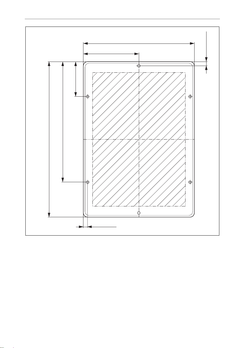
257 mm
81 mm
9,50 mm
9,50 mm
128,50 mm
360 mm
281 mm
4
CS-NC15, CS-NCVM
6
Page 7
CS-NC15, CS-NCVM
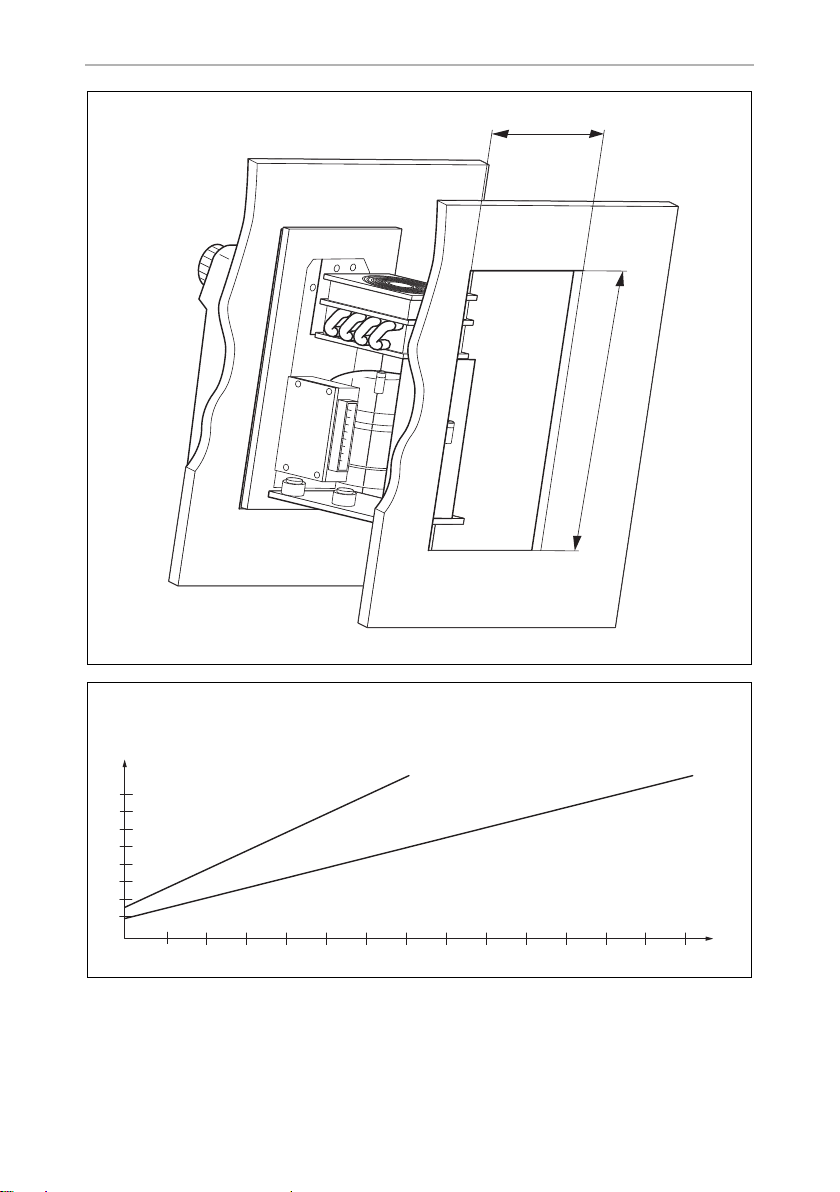
~ 215 mm
~ 310 mm
5
6
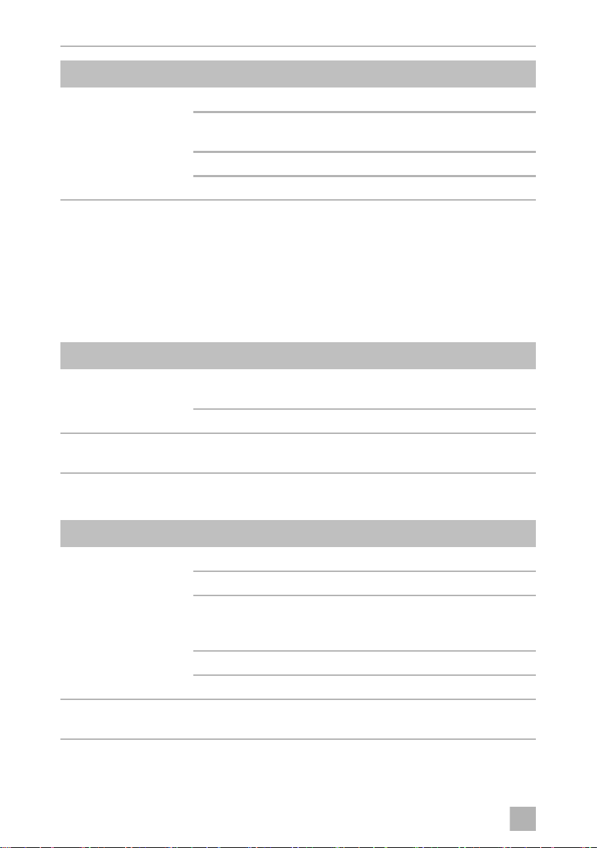
Ø
/mm²
14
10
6
2
0
0 2 4 6 8 10 12 14 16 18 20 22 24 26 28
12 V
24 V
l/m
7
Page 8

EN
Explanation of symbols CS-NC15, CS-NCVM
Please read this instruction manual carefully before installation and first
use, and store it in a safe place. If you pass on the product to another
person, hand over this instruction manual along with it.
Contents
1 Explanation of symbols. . . . . . . . . . . . . . . . . . . . . . . . . . . . . . . . . . . . . . . . . . .8
2 Safety instructions . . . . . . . . . . . . . . . . . . . . . . . . . . . . . . . . . . . . . . . . . . . . . . .9
3 Scope of delivery . . . . . . . . . . . . . . . . . . . . . . . . . . . . . . . . . . . . . . . . . . . . . . 11
4 Accessories . . . . . . . . . . . . . . . . . . . . . . . . . . . . . . . . . . . . . . . . . . . . . . . . . . . 11
5 Intended use . . . . . . . . . . . . . . . . . . . . . . . . . . . . . . . . . . . . . . . . . . . . . . . . . .12
6 Technical description . . . . . . . . . . . . . . . . . . . . . . . . . . . . . . . . . . . . . . . . . . .12
7 Installing the cooling unit . . . . . . . . . . . . . . . . . . . . . . . . . . . . . . . . . . . . . . . .13
8 Using the cooling unit. . . . . . . . . . . . . . . . . . . . . . . . . . . . . . . . . . . . . . . . . . .16
9 Troubleshooting . . . . . . . . . . . . . . . . . . . . . . . . . . . . . . . . . . . . . . . . . . . . . . .17
10 Guarantee . . . . . . . . . . . . . . . . . . . . . . . . . . . . . . . . . . . . . . . . . . . . . . . . . . . .19
11 Disposal . . . . . . . . . . . . . . . . . . . . . . . . . . . . . . . . . . . . . . . . . . . . . . . . . . . . . .19
12 Technical data . . . . . . . . . . . . . . . . . . . . . . . . . . . . . . . . . . . . . . . . . . . . . . . . 20
1 Explanation of symbols
DANGER!
D
!
!
8
Safety instruction: Failure to observe this instruction will cause death
or serious injury.
WARNING!
Safety instruction: Failure to observe this instruction can cause death
or serious injury.
CAUTION!
Safety instruction: Failure to observe this instruction can lead to injury.
Page 9

EN
CS-NC15, CS-NCVM Safety instructions
NOTICE!
A
I
Failure to observe this instruction can cause material damage and impair
the function of the product.
NOTE
Supplementary information for operating the product.
2 Safety instructions
The manufacturer accepts no liability for damage in the following cases:
•
Faulty assembly or connection
•
Damage to the product resulting from mechanical influences and incorrect
connection voltage
•
Alterations to the product without express permission from the manufacturer
•
Use for purposes other than those described in the operating manual
2.1 General safety
DANGER!
•
D
Danger of fatal injuries!
When using the device on boats: if the device is powered by the
electric power system, ensure that the power supply has a residual
current circuit breaker!
!
WARNING!
•
Installations in washrooms and areas exposed to water, must be
performed by a qualified technician.
•
Do not operate the device if it is visibly damaged.
•
This device may only be repaired by qualified personnel. Inadequate
repairs can lead to considerable hazards.
Should your device need to be repaired, please contact customer
services.
•
Do not open the refrigerant circuit under any circumstances. An
exception to this is when the device has to be disconnected for return
shipping.
•
Set up the device in a dry location where it is protected against splashing water.
9
Page 10

EN
Safety instructions CS-NC15, CS-NCVM
•
Do not place the device near naked flames or other heat sources
(heaters, direct sunlight, gas ovens etc.).
•
Make sure that the compressor is sufficiently ventilated.
•
Electronic devices are not toys!
Always keep and use the device out of the reach of children.
•
People (including children) whose physical, sensory or mental
capacities or whose lack of experience or knowledge prevent them
from using this product safely should not use it without the supervision
or instruction of a responsible person.
•
Before you start up the device for the first time, check that the operating voltage matches the battery voltage (see type plate).
•
If the connection cable is damaged, it must be replaced to prevent
possible electrical hazards. Only replace a damaged connection
cable with a connection cable of the same type and specifications.
•
Do not store any explosive substances, such as spray cans with
propellants in the device.
2.2 Operating the device safely
DANGER! Danger of fatal injuries!
•
D
Do not touch exposed cables with your bare hands. This especially
applies when operating the device from the AC power supply.
A
I
10
NOTICE!
•
Never use cleaners that contain sand, acids or solvents to clean the
vaporiser.
•
Protect the device against rain and moisture.
•
Disconnect the cooling device and other consumer units from the
battery before you connect the quick charging device.
NOTE
•
Disconnect the device if you are not going to use it for a prolonged
period.
Page 11

EN
CS-NC15, CS-NCVM Scope of delivery
2.3 Safety precautions when handling batteries
CAUTION! Danger of injury!
•
!
Batteries contain aggressive and caustic acids. Avoid battery fluid
coming into contact with your body. If your skin does come into
contact with battery fluid, wash the part of your body in question
thoroughly with water.
•
If you connect the device to a battery, make sure that no food comes
into contact with the battery acid.
3Scope of delivery
Quantity Description
1 Cooling unit with vaporiser
1 Operating manual
4Accessories
If you wish to operate the cooling unit from the AC power supply, please use one of
the following rectifiers.
Available as accessory (not included in scope of delivery):
Description
CoolPower EPS100 rectifier (230 Vw to 24 Vg)
For devices with BD35F compressor
CoolPower MPS35 rectifier (110 – 240 Vw to 24 Vg)
For devices with BD35F compressor
Reference
number
9600000440
9600000445
11
Page 12

EN
Intended use CS-NC15, CS-NCVM
5 Intended use
The cooling unit is suited for building your own refrigerator or cooler.
The cooler unit is suitable for cooling food. The device is also suitable for use on
boats.
CAUTION! Health hazard!
!
Please check if the cooling capacity of the device is suitable for storing
the food or medicine you wish to cool.
6 Technical description
The cooling units are suitable for use with DC voltage and can therefore be used
for camping or on boats. Furthermore, you can connect them to a AC power supply
via the rectifiers (see chapter “Accessories” on page 11).
The cooling device can withstand a short term inclination of 30°, for example on
boats.
Use the continuously variable thermostat to set the desired temperature.
Battery monitor
The cooling device is equipped with an electronic device to protect against reversing the polarity when connecting to a battery. To protect the battery, the cooling
device switches off automatically if the voltage is insufficient (see following table).
Connection voltage Switch-off voltage Restart voltage
12 V
24 V
10.4 V 11.7 V
22.8 V 24.2 V
12
Page 13

EN
CS-NC15, CS-NCVM Installing the cooling unit
7 Installing the cooling unit
7.1 Tools required
For installation and assembly, you will need the following tools:
•
Drill
•
Screwdriver
•
Open-ended spanner: 16 mm, 19 mm and 21 mm
•
Sealant and PUR foam
•
Cable, cable lugs and cable clips
7.2 Notes on the cooling container
Permitted cooling area contents
Make sure that maximum cooling area contents specified are not exceeded for the
respective vaporiser type (see chapter “Technical data” on page 20).
Minimum insulation
The maximum cooling area contents are based on a minimum insulation thickness of
35 mm of foam polyurethane with a density of 40 kg/m³. If other insulating materials
are used such as styrofoam, double the wall thickness to attain the same level of heat
insulation.
Keys for the illustrations
No. in fig. 1,
page 3
1 DC fan
2 Thermostat button
3 Connection plug for DC fan
4 Thermostat
5 Connection cable
Explanation
13
Page 14

EN
Installing the cooling unit CS-NC15, CS-NCVM
No. in fig. 2,
page 4
A
1 Connection cable
NOTICE!
Carefully insulate and seal off the wall openings after installation to
prevent moisture penetration.
Explanation
7.3 Installing the cooling unit
It is important to select the proper location for setting up the unit. To ensure troublefree operation, please note the following points:
•
Set up the cooling unit in a dry, sheltered place. Avoid placing it near heat
sources such as radiators, gas ovens or hot water pipes. Do not place in direct
sunlight.
•
On a boat, install the cooling unit, if possible, below the waterline.
•
The refrigeration unit functions at a short-term inclination of up to 30°. Install the
unit on a flat base.
•
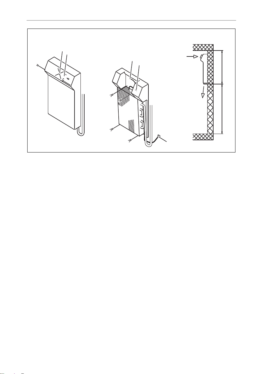
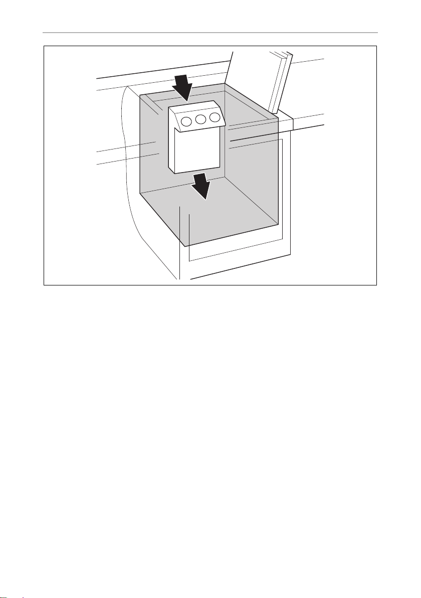
The cooled air must dissipate unhindered (fig. 3, page 5).
•
When installing the cooling unit in a closed room such as a wardrobe, pantry or
aft compartment, openings must have a cross section of at least 200 cm²
(25cmx8cm) for cooling and exhaust air.
•
Make sure that the air flow on the condenser (fig. 3, page 5) is not restricted.
•
Maintain a minimum distance between the condenser and adjoining wall of
50 mm.
Observe the drilling template (fig. 4, page 6) and the installation drawing (fig. 5,
page 7).
14
Page 15

EN
CS-NC15, CS-NCVM Installing the cooling unit
7.4 Connecting the cooling unit
Connecting to a battery
The cooling unit can be operated from a DC voltage supply.
NOTICE!
A
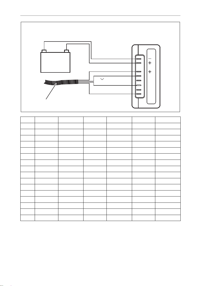
➤ Determine the required cross section of the cable in relation to the cable length
according to fig. 6, page 7.
Key for fig. 6, page 7:
A
➤ Before you start up the unit for the first time, check that the operating voltage
matches the battery voltage (see type plate).
To avoid voltage loss and therefore a drop in performance, the cable
should be kept as short as possible and should not be interrupted.
For this reason avoid additional switches, plugs or power strips.
Co-ordinate axis Meaning Unit
l Cable length m
∅ Cable cross section mm²
NOTICE!
Make sure that the polarity is correct.
➤ Connect your cooling unit
– as directly as possible to the pole of the battery or
– to a plug socket which is fuse protected with at least 15 A (at 12 V) or 7.5 A (at
24 V).
NOTICE!
A
For safety reasons the cooling unit is equipped with an electronic system to prevent
polarity reversal. This protects the cooling unit when it is connected to a battery.
Disconnect the cooling device and other power consuming devices
from the battery before you connect the battery to a quick charging
device. Overvoltage can damage the electronics of the device.
15
Page 16

EN
Using the cooling unit CS-NC15, CS-NCVM
Connecting to an AC power supply
WARNING!
•
!
➤ To operate the cooling unit from the AC power supply, use the rectifier
– CoolPower EPS100 (230 Vw to 24 V
– CoolPower MPS35 (110 – 240 Vw to 24 V
pressor
I
Never handle plugs and switches with wet hands or if you are
standing on a wet surface.
•
If you are operating your cooling device on board a boat with an AC
power supply from the land, you must install a residual current circuit
breaker between the AC power supply and the cooling device.
Seek advice from a trained technician.
g) for devices with BD35F compressor
g) for devices with BD35F com-
NOTE
The output voltage of the described rectifier is 24 V. Please remember
this when connecting other consumers at a later time.
8 Using the cooling unit
8.1 Energy saving tips
•
Choose a well ventilated installation location which is protected from direct
sunlight.
•
Allow hot food to cool down first before placing it in the device.
•
Do not open the refrigerated container more often than necessary.
•
Do not leave the door open for longer than necessary.
•
Defrost the refrigerated container once a layer of ice forms.
•
Avoid unnecessary low temperatures.
•
Clean the condenser of dust and dirt at regular intervals.
•
Clean the lid seal regularly.
16
Page 17

EN
CS-NC15, CS-NCVM Troubleshooting
8.2 Start the cooling unit
➤ Switch in the cooling unit by turning the control button clockwise (fig. 1 2,
page 3).
If you turn the control button further, you can regulate the temperature.
8.3 Shutting down the cooling unit
If you do not intend to use the cooling device for a prolonged period, proceed as
follows:
➤ Turn the control to 0.
➤ Disconnect the power cable from the battery or pull the DC cable plug out of the
rectifier.
➤ Clean the cooling device.
➤ Leave the door slightly open over the cover.
This prevents odour build-up.
9 Troubleshooting
Compressor does not run
Fault Possible cause Remedy
UT = 0 V The connection between the battery
and the electronics is interrupted
Main switch defective (if installed) Replace the main switch
Additional supply line fuse has blown
(if installed)
U
≤ U
T
ON
Start attempt with
U
≤ U
T
OFF
Battery voltage is too low Charge the battery
Loose cables
Poor contact (corrosion)
Battery capacity too low Replace the battery
Cable cross section too low Replace the cable
Establish a connection
Replace the fuse
Establish a connection
(fig. 6, page 7)
17
Page 18
EN
Troubleshooting CS-NC15, CS-NCVM
Fault Possible cause Remedy
Start attempt with
UT≥ U
ON
Voltage between the positive and negative electronic terminals
U
T
U
Switch-on voltage of the electronics
ON
Switch-off voltage of the electronics
U
OFF
Ambient temperature too high –
Insufficient ventilation and/or cooling Provide improved ventila-
tion for the cooling unit
Condenser is dirty Clean the condenser
Fan defective (if installed) Replace the fan
Interior temperature too low in control setting 1
Fault Possible cause Remedy
Compressor runs
constantly
Compressor runs for
along time
Thermostat sensor has no contact on
the vaporiser
Thermostat defective Change the thermostat
Large quantities have been frozen in
the freezer compartment
Secure the sensor
–
Cooling capacity drops, interior temperature rises
Fault Possible cause Remedy
Compressor runs for a
long time/continuously
Compressor runs
infrequently
Vaporiser is iced over Defrost the vaporiser
Ambient temperature too high –
Insufficient ventilation and/or cooling Provide improved
ventilation for the
cooling unit
Condenser is dirty Clean the condenser
Fan defective (if installed) Replace the fan
Battery capacity exhausted Charge the battery
18
Page 19

EN
CS-NC15, CS-NCVM Guarantee
Unusual noises
Fault Possible cause Remedy
Loud humming A component of the refrigerant circuit
cannot move freely (lies against the
wall)
Foreign body jammed between the
cooling device and the wall
Fan noise (if installed) Clean the fan blades
Bend the component
carefully away from the
obstruction
Remove the foreign body
10 Guarantee
The statutory warranty period applies. If the product is defective, please contact the
manufacturer's branch in your country (see the back of the instruction manual for the
addresses) or your retailer.
For repair and warranty processing, please include the following documents when
you send in the device:
•
A copy of the receipt with purchasing date
•
A reason for the claim or description of the fault
11 Disposal
➤ Place the packaging material in the appropriate recycling waste bins wherever
possible.
M
If you wish to finally dispose of the product, ask your local recycling centre
or specialist dealer for details about how to do this in accordance with the
applicable disposal regulations.
19
Page 20
EN
Technical data CS-NC15, CS-NCVM
12 Technical data
CS-NC15 CS-NCVM
Max. refrigeration capacity at
35 mm PU insulation:
Max. refrgeration capacity at
50 mm PU insultion:
Power consumption: 48 W 60 W
Connection voltage: 12 Vg or 24 Vg
Refrigerant: R134a
Coolant quantity: 60 g
CO2 equivalent: 0.086 t
Global warming potential (GWP): 1430
Dimensions (WxHxD): 258x363x240mm
Wei ght: 9 k g
Test/certificates:
200 l 200 l
250 l 250 l
Contains fluorinated greenhouse gases
Hermetically sealed equipment
20
Page 21

DE
CS-NC15, CS-NCVM Erklärung der Symbole
Bitte lesen Sie diese Anleitung vor Einbau und Inbetriebnahme sorgfältig
durch und bewahren Sie sie auf. Geben Sie sie im Falle einer Weitergabe
des Produktes an den Nutzer weiter.
Inhaltsverzeichnis
1 Erklärung der Symbole . . . . . . . . . . . . . . . . . . . . . . . . . . . . . . . . . . . . . . . . . . 21
2 Sicherheitshinweise . . . . . . . . . . . . . . . . . . . . . . . . . . . . . . . . . . . . . . . . . . . 22
3 Lieferumfang . . . . . . . . . . . . . . . . . . . . . . . . . . . . . . . . . . . . . . . . . . . . . . . . . 24
4 Zubehör. . . . . . . . . . . . . . . . . . . . . . . . . . . . . . . . . . . . . . . . . . . . . . . . . . . . . 24
5 Bestimmungsgemäßer Gebrauch . . . . . . . . . . . . . . . . . . . . . . . . . . . . . . . . 25
6 Technische Beschreibung . . . . . . . . . . . . . . . . . . . . . . . . . . . . . . . . . . . . . . 25
7 Kühlaggregat einbauen . . . . . . . . . . . . . . . . . . . . . . . . . . . . . . . . . . . . . . . . 26
8 Kühlaggregat benutzen . . . . . . . . . . . . . . . . . . . . . . . . . . . . . . . . . . . . . . . . 29
9 Störungen beseitigen . . . . . . . . . . . . . . . . . . . . . . . . . . . . . . . . . . . . . . . . . . 30
10 Gewährleistung. . . . . . . . . . . . . . . . . . . . . . . . . . . . . . . . . . . . . . . . . . . . . . . 32
11 Entsorgung . . . . . . . . . . . . . . . . . . . . . . . . . . . . . . . . . . . . . . . . . . . . . . . . . . 32
12 Technische Daten . . . . . . . . . . . . . . . . . . . . . . . . . . . . . . . . . . . . . . . . . . . . . 33
1 Erklärung der Symbole
GEFAHR!
D
!
!
Sicherheitshinweis: Nichtbeachtung führt zu Tod oder schwerer
Verletzung.
WARNUNG!
Sicherheitshinweis: Nichtbeachtung kann zu Tod oder schwerer
Verletzung führen.
VORSICHT!
Sicherheitshinweis: Nichtbeachtung kann zu Verletzungen führen.
21
Page 22

DE
Sicherheitshinweise CS-NC15, CS-NCVM
ACHTUNG!
A
I
Nichtbeachtung kann zu Materialschäden führen und die Funktion des
Produktes beeinträchtigen.
HINWEIS
Ergänzende Informationen zur Bedienung des Produktes.
2 Sicherheitshinweise
Der Hersteller übernimmt in folgenden Fällen keine Haftung für Schäden:
•
Montage- oder Anschlussfehler
•
Beschädigungen am Produkt durch mechanische Einflüsse und falsche
Anschlussspannung
•
Veränderungen am Produkt ohne ausdrückliche Genehmigung vom Hersteller
•
Verwendung für andere als die in der Anleitung beschriebenen Zwecke
2.1 Allgemeine Sicherheit
GEFAHR!
•
D
Lebensgefahr!
Beim Einsatz auf Booten: Sorgen Sie bei Netzbetrieb unbedingt
dafür, dass Ihre Stromversorgung über einen FI-Schutzschalter abgesichert ist!
!
22
WARNUNG!
•
Lassen Sie Installationen in Feuchträumen nur vom Fachmann verlegen.
•
Wenn das Produkt sichtbare Beschädigungen aufweist, dürfen Sie es
nicht in Betrieb nehmen.
•
Reparaturen an diesem Produkt dürfen nur von Fachkräften durchgeführt werden. Durch unsachgemäße Reparaturen können erhebliche
Gefahren entstehen.
Wenden Sie sich im Reparaturfall an den Kundendienst.
•
Öffnen Sie auf keinen Fall den Kühlkreislauf. Eine Ausnahme besteht,
wenn Sie das Produkt für den Rückversand entkoppeln müssen.
•
Stellen Sie das Produkt an einem trockenen und gegen Spritzwasser
geschützten Platz auf.
Page 23

DE
CS-NC15, CS-NCVM Sicherheitshinweise
•
Stellen Sie das Produkt nicht in der Nähe von offenen Flammen oder
anderen Wärmequellen (Heizung, starke Sonneneinstrahlung,
Gasöfen usw.) ab.
•
Achten Sie darauf, dass der Kompressor ausreichend belüftet wird.
•
Elektrogeräte sind kein Kinderspielzeug!
Verwahren und benutzen Sie das Gerät außerhalb der Reichweite von
Kindern.
•
Personen (einschließlich Kinder), die aufgrund ihrer physischen, sensorischen oder geistigen Fähigkeiten oder ihrer Unerfahrenheit oder
Unkenntnis nicht in der Lage sind, das Produkt sicher zu benutzen,
sollten dieses Produkt nicht ohne Aufsicht oder Anweisung durch eine
verantwortliche Person nutzen.
•
Kontrollieren Sie vor Inbetriebnahme des Produktes, ob die Betriebsspannung und die Batteriespannung übereinstimmen (siehe Typenschild).
•
Wenn das Anschlusskabel beschädigt ist, müssen Sie es ersetzen, um
Gefährdungen zu vermeiden. Tauschen Sie ein beschädigtes
Anschlusskabel nur gegen ein Anschlusskabel gleicher Art und
Spezifikation aus.
•
Lagern Sie keine explosionsfähigen Substanzen wie z. B. Sprühdosen
mit Treibgas im Produkt.
2.2 Sicherheit beim Betrieb des Produktes
GEFAHR!
•
D
A
I
Lebensgefahr!
Fassen Sie nie mit bloßen Händen an blanke Leitungen. Dies gilt vor
allem beim Betrieb am Wechselstrom.
ACHTUNG!
•
Verwenden Sie nie sand-, säure- oder lösungsmittelhaltige Putzmittel
zur Reinigung des Verdampfers.
•
Schützen Sie das Produkt vor Regen und Feuchtigkeit.
•
Klemmen Sie das Kühlaggregat und andere Verbraucher von der
Batterie ab, bevor Sie ein Schnellladegerät anschließen.
HINWEIS
•
Klemmen Sie das Produkt ab, wenn Sie es lange nicht brauchen.
23
Page 24
DE
Lieferumfang CS-NC15, CS-NCVM
2.3 Sicherheit beim Umgang mit Batterien
VORSICHT! Verletzungsgefahr!
•
!
Batterien können aggressive und ätzende Säuren enthalten. Verhindern Sie jeden Körperkontakt mit der Batterieflüssigkeit. Sollte es
doch zur Berührung mit Batterieflüssigkeit kommen, so spülen Sie das
entsprechende Körperteil gründlich mit Wasser ab.
•
Wenn Sie das Produkt an eine Batterie anschließen, stellen Sie sicher,
dass Lebensmittel nicht mit Batteriesäure in Berührung kommen.
3 Lieferumfang
Menge Bezeichnung
1 Kühlaggregat mit Verdampfer
1 Bedienungsanleitung
4Zubehör
Falls Sie das Kühlaggregat am Wechselstrom betreiben wollen, verwenden Sie bitte
einen der folgenden Gleichrichter.
Als Zubehör erhältlich (nicht im Lieferumfang enthalten):
Bezeichnung Artikel-Nr.
CoolPower EPS100 Gleichrichter (230 Vw zu 24 Vg)
für Geräte mit Kompressor BD35F
CoolPower MPS35 Gleichrichter (110 – 240 Vw zu 24 Vg)
für Geräte mit Kompressor BD35F
9600000440
9600000445
24
Page 25

DE
CS-NC15, CS-NCVM Bestimmungsgemäßer Gebrauch
5 Bestimmungsgemäßer Gebrauch
Das Kühlaggregat eignet sich zum Selbstbau eines Kühlschrankes oder einer
Kühlbox.
Das Kühlaggregat eignet sich zum Kühlen von Lebensmitteln. Das Gerät ist auch für
den Betrieb auf Booten geeignet.
VORSICHT! Gesundheitsgefahr!
!
Prüfen Sie bitte, ob die Kühlleistung des Gerätes den Anforderungen
der Lebensmittel oder Medikamente entspricht, die Sie kühlen wollen.
6 Technische Beschreibung
Die Kühlaggregate sind geeignet für den Einsatz an Gleichspannung und können
somit z. B. auch beim Camping oder auf Booten eingesetzt werden. Außerdem können sie über Gleichrichter an Wechselstrom angeschlossen werden (siehe Kapitel
„Zubehör“ auf Seite 24).
Das Kühlgerät kann auch in Umgebungsbedingungen eingesetzt werden, in denen
es zu kurzzeitigen Krängung von 30° kommt, z.B. beim Einsatz in Booten.
Über den Thermostat kann die gewünschte Temperatur stufenlos eingestellt
werden.
Batteriewächter
Ein elektronischer Verpolungsschutz schützt das Produkt gegen Verpolung beim
Batterieanschluss. Zum Schutz der Batterie schaltet sich das Produkt automatisch ab,
wenn die Spannung nicht mehr ausreicht (siehe folgende Tabellen).
Anschlussspannung Ausschaltspannung
12 V
24 V
10,4 V 11,7 V
22,8 V 24,2 V
Wiedereinschaltspannung
25
Page 26

DE
Kühlaggregat einbauen CS-NC15, CS-NCVM
7 Kühlaggregat einbauen
7.1 Benötigtes Werkzeug
Für Einbau und Montage benötigen Sie folgende Werkzeuge:
•
Bohrmaschine
•
Schraubendreher
•
Maulschlüssel: 16 mm, 19 mm und 21 mm
•
Dichtungsmasse und Montageschaum
•
Kabel, Kabelschuhe und Kabelschellen
7.2 Hinweise zum Kühlbehälter
Zulässige Kühlrauminhalte
Achten Sie darauf, dass der angegebene maximale Kühlrauminhalt für den jeweiligen Verdampfer-Typ nicht überschritten wird (siehe Kapitel „Technische Daten“ auf
Seite 33).
Mindestisolierung
Der maximale Kühlrauminhalt basiert auf einer Mindestisolierung von 35 mm
geschäumtem Polyurethan mit einem Raumgewicht von 40 kg/m³. Bei Verwendung
anderer Isolierstoffe wie z. B. Styropor sind die Wandstärken zu verdoppeln, um die
gleiche Wärmedämmung zu erreichen.
Legenden zu den Abbildungen
Nr. in
Abb. 1, Seite 3
1 DC-Lüfter
2 Thermostatknopf
3 Anschlussstecker DC-Lüfter
4 Thermostat
5Anschlusskabel
Erklärung
26
Page 27

DE
CS-NC15, CS-NCVM Kühlaggregat einbauen
Nr. in
Abb. 2, Seite 4
1Anschlusskabel
ACHTUNG!
A
Isolieren und dichten Sie die Wanddurchbrüche nach erfolgter
Montage wieder sorgfältig gegen Eindringen von Feuchtigkeit ab.
Erklärung
7.3 Kühlaggregat montieren
Die richtige Platzwahl für die Aufstellung des Aggregates ist besonders wichtig. Um
ein einwandfreies Funktionieren des Gerätes sicherzustellen, beachten Sie folgende
Punkte:
•
Stellen Sie das Kühlaggregat an einem trockenen, geschützten Platz auf.
Vermeiden Sie das Aufstellen neben Wärmequellen wie Heizungen, Gasöfen,
Warmwasserleitungen etc. Lassen Sie das Kühlaggregat nicht in der prallen
Sonne stehen.
•
Installieren Sie das Kühlaggregat auf Booten möglichst unterhalb der
Wasserlinie.
•
Das Kühlaggregat funktioniert bei einem Neigungswinkel von bis zu 30°.
Installieren Sie das Kühlgerät auf einer geraden Ebene.
•
Die gekühlte Luft muss ungehindert abziehen können (Abb. 3, Seite 5).
•
Bei Einbau des Kühlaggregates in einen geschlossenen Raum wie Kleiderschrank, Pantry oder Backkiste müssen Öffnungen mit einem freien Querschnitt
von je mindestens 200 cm² (25 cm x 8 cm) für Be- und Entlüftung vorgesehen
werden.
•
Achten Sie darauf, dass der Luftstrom am Kondensator (Abb. 3, Seite 5) nicht
beeinträchtigt wird.
•
Halten Sie einen Mindestabstand zwischen Kondensator und angrenzender
Wand ein (50 mm).
Beachten Sie zur Montage die Abbildung der Bohrschablone (Abb. 4, Seite 6) und
die Einbauzeichnung (Abb. 5, Seite 7).
27
Page 28

DE
Kühlaggregat einbauen CS-NC15, CS-NCVM
7.4 Kühlaggregat anschließen
An eine Batterie anschließen
Das Kühlaggregat kann mit Gleichstrom betrieben werden.
ACHTUNG!
A
➤ Bestimmen Sie den notwendigen Querschnitt der Leitung in Abhängigkeit von
der Leitungslänge gemäß Abb. 6, Seite 7.
Legende zu Abb. 6, Seite 7:
A
➤ Kontrollieren Sie vor Inbetriebnahme des Aggregates, ob die Betriebsspannung
und die Batteriespannung übereinstimmen (siehe Typenschild).
Um Spannungs- und Leistungsverluste zu vermeiden, muss die Leitung
möglichst kurz und nicht unterbrochen sein.
Vermeiden Sie deshalb zusätzliche Schalter, Stecker oder Verteilerdosen.
Koordinatenachse Bedeutung Einheit
l Leitungslänge m
∅ Leitungsquerschnitt mm²
ACHTUNG!
Beachten Sie die richtige Polarität.
➤ Schließen Sie Ihr Kühlaggregat
– möglichst direkt an die Pole der Batterie an oder
– an einen Steckplatz an, der mit mindestens 15 A (bei 12 V) bzw. 7,5 A (bei
24 V) abgesichert ist.
ACHTUNG!
A
Zur Sicherheit ist das Kühlaggregat mit einem elektronischen Verpolungsschutz ausgestattet, der das Kühlaggregat gegen Verpolung beim Batterieanschluss schützt.
28
Klemmen Sie das Gerät und andere Verbraucher von der Batterie ab,
bevor Sie die Batterie mit einem Schnellladegerät aufladen. Überspannungen können die Elektronik der Geräte beschädigen.
Page 29

DE
CS-NC15, CS-NCVM Kühlaggregat benutzen
An Wechselstrom anschließen
WARNUNG!
•
!
➤ Um das Kühlaggregat am Wechselstrom zu betreiben, verwenden Sie den
Gleichrichter:
– CoolPower EPS100 (230 Vw zu 24 Vg) bei Geräten mit Kompressor BD 35F
– CoolPower MPS35 (110 – 240 Vw zu 24 Vg) bei Geräten mit Kompressor
BD35F
I
Hantieren Sie nie mit Steckern und Schaltern, wenn Sie nasse Hände
haben oder mit den Füßen in der Nässe stehen.
•
Wenn Sie Ihr Produkt an Bord eines Bootes per Landanschluss am
Wechselstrom betreiben, müssen Sie auf jeden Fall einen FI-Schutzschalter zwischen Wechselstromnetz und Produkt schalten.
Lassen Sie sich von einem Fachmann beraten.
HINWEIS
Die Ausgangsspannung der beschriebenen Gleichrichter beträgt 24 V.
Bitte beachten Sie dies beim eventuellen Anschluss weiterer
Verbraucher.
8 Kühlaggregat benutzen
8.1 Tipps zum Energiesparen
•
Wählen Sie einen gut belüfteten und vor Sonnenstrahlen geschützten Einsatzort.
•
Lassen Sie warme Speisen erst abkühlen, bevor Sie sie einlagern.
•
Öffnen Sie den Kühlbehälter nicht häufiger als nötig.
•
Lassen Sie die Tür nicht länger offen stehen als nötig.
•
Tauen Sie den Kühlbehälter ab, sobald sich eine Eisschicht gebildet hat.
•
Vermeiden Sie eine unnötig tiefe Innentemperatur.
•
Befreien Sie den Kondensator in regelmäßigen Abständen von Staub und
Verunreinigungen.
•
Reinigen Sie regelmäßig die Deckeldichtung.
29
Page 30

DE
Störungen beseitigen CS-NC15, CS-NCVM
8.2 Kühlaggregat in Betrieb nehmen
➤ Schalten Sie das Kühlaggregat mit einer Rechtsdrehung des Thermostatknopfes
(Abb. 1 2, Seite 3) ein.
Wenn Sie den Knopf weiter drehen, können Sie die Temperatur regeln.
8.3 Kühlaggregat außer Betrieb nehmen
Wenn Sie das Kühlaggregat für längere Zeit stilllegen wollen, gehen Sie wie folgt
vor:
➤ Drehen Sie den Regler auf Stufe „0“.
➤ Klemmen Sie die Anschlusskabel von der Batterie ab oder ziehen Sie den Stecker
der Gleichstromleitung aus dem Gleichrichter.
➤ Reinigen Sie das Produkt.
➤ Lassen Sie die Tür oder den Deckel leicht geöffnet.
So verhindern Sie, dass sich Gerüche bilden.
9 Störungen beseitigen
Kompressor läuft nicht
Störung Mögliche Ursache Lösung
UKL = 0 V Unterbrechung in der Anschluss-
leitung Batterie – Elektronik
Hauptschalter defekt (falls
vorhanden)
Zusätzliche Leitungsabsicherung
durchgebrannt (falls vorhanden)
≤ U
U
KL
EIN
Startversuch mit
U
≤ U
KL
AUS
Batteriespannung zu niedrig Batterie laden
Lose Kabelverbindung
Schlechter Kontakt (Korrosion)
Batteriekapazität zu gering Batterie wechseln
Kabelquerschnitt zu gering Kabel wechseln
Verbindung herstellen
Hauptschalter wechseln
Leitungsabsicherung
wechseln
Verbindung herstellen
(Abb. 6, Seite 7)
30
Page 31

DE
CS-NC15, CS-NCVM Störungen beseitigen
Störung Mögliche Ursache Lösung
Startversuch mit
UKL≥ U
EIN
Spannung zwischen Plus- und Minusklemme der Elektronik
U
KL
U
Einschaltspannung Elektronik
EIN
U
Ausschaltspannung Elektronik
AUS
Umgebungstemperatur zu hoch –
Be- und Entlüftung nicht ausreichend für bessere Be- und
Entlüftung des Kühlaggregats sorgen
Kondensator verschmutzt Kondensator reinigen
Lüfter defekt (falls vorhanden) Lüfter wechseln
Innentemperatur zu kalt in Regler-Stufe „1“
Störung Mögliche Ursache Lösung
Kompressor läuft
dauernd
Kompressor läuft lange Im Gefrierfach wurde größere Menge
Thermostat-Fühler hat keinen Kontakt
am Verdampfer
Thermostat defekt Thermostat wechseln
eingefroren
Fühler befestigen
–
Kühlleistung lässt nach, Innentemperatur steigt
Störung Mögliche Ursache Lösung
Kompressor läuft
lange/dauernd
Kompressor läuft selten Batteriekapazität erschöpft Batterie laden
Verdampfer vereist Verdampfer abtauen
Umgebungstemperatur zu hoch –
Be- und Entlüftung nicht ausreichend für bessere Be- und
Entlüftung des Kühlaggregats sorgen
Kondensator verschmutzt Kondensator reinigen
Lüfter defekt (falls vorhanden) Lüfter wechseln
31
Page 32

DE
Gewährleistung CS-NC15, CS-NCVM
Ungewöhnliche Geräusche
Störung Mögliche Ursache Lösung
Lautes Brummen Bauteil des Kältekreislaufes kann nicht
frei schwingen (liegt an Wandung an)
Fremdkörper zwischen Kühlmaschine
und Wand eingeklemmt
Lüftergeräusch (falls vorhanden) Lüfterflügel reinigen
Bauteil vorsichtig
abbiegen
Fremdkörper entfernen
10 Gewährleistung
Es gilt die gesetzliche Gewährleistungsfrist. Sollte das Produkt defekt sein, wenden
Sie sich bitte an die Niederlassung des Herstellers in Ihrem Land (Adressen siehe
Rückseite der Anleitung) oder an Ihren Fachhändler.
Zur Reparatur- bzw. Gewährleistungsbearbeitung müssen Sie folgende Unterlagen
mitschicken:
•
eine Kopie der Rechnung mit Kaufdatum,
•
einen Reklamationsgrund oder eine Fehlerbeschreibung.
11 Entsorgung
➤ Geben Sie das Verpackungsmaterial möglichst in den entsprechenden
Recycling-Müll.
M
32
Wenn Sie das Produkt endgültig außer Betrieb nehmen, informieren Sie
sich bitte beim nächsten Recyclingcenter oder bei Ihrem Fachhändler
über die zutreffenden Entsorgungsvorschriften.
Page 33

DE
CS-NC15, CS-NCVM Technische Daten
12 Technische Daten
CS-NC15 CS-NCVM
Max. Kühlrauminhalt bei 50 mm
PU-Isolierung:
Max. Kühlrauminhalt bei 35 mm
PU-Isolierung:
Leistungsaufnahme: 48 W 60 W
Anschlussspannung: 12 Vg oder 24 Vg
Kühlmittel: R134a
Kühlmittelmenge: 60 g
CO2-Äquivalent: 0,086 t
Treibhauspotential (GWP): 1430
Abmessungen (BxHxT): 258x363x240mm
Gewicht: 9 kg
Prüfung/Zertifikat:
250 l 200 l
200 l 250 l
Enthält fluorierte Treibhausgase
Hermetisch geschlossene Einrichtung
33
Page 34

FR
Explication des symboles CS-NC15, CS-NCVM
Veuillez lire attentivement cette notice avant le montage et la mise en
service. Veuillez ensuite la conserver. En cas de passer le produit, veuillez
le transmettre au nouvel acquéreur.
Sommaire
1 Explication des symboles . . . . . . . . . . . . . . . . . . . . . . . . . . . . . . . . . . . . . . . 34
2 Consignes de sécurité . . . . . . . . . . . . . . . . . . . . . . . . . . . . . . . . . . . . . . . . . 35
3 Contenu de la livraison . . . . . . . . . . . . . . . . . . . . . . . . . . . . . . . . . . . . . . . . . 37
4 Accessoires . . . . . . . . . . . . . . . . . . . . . . . . . . . . . . . . . . . . . . . . . . . . . . . . . . 37
5 Usage conforme . . . . . . . . . . . . . . . . . . . . . . . . . . . . . . . . . . . . . . . . . . . . . . 38
6 Description technique . . . . . . . . . . . . . . . . . . . . . . . . . . . . . . . . . . . . . . . . . 38
7 Installation du groupe frigorifique . . . . . . . . . . . . . . . . . . . . . . . . . . . . . . . . 39
8 Utilisation du groupe frigorifique . . . . . . . . . . . . . . . . . . . . . . . . . . . . . . . . . 42
9 Recherche des pannes . . . . . . . . . . . . . . . . . . . . . . . . . . . . . . . . . . . . . . . . . 43
10 Garantie. . . . . . . . . . . . . . . . . . . . . . . . . . . . . . . . . . . . . . . . . . . . . . . . . . . . . 45
11 Élimination. . . . . . . . . . . . . . . . . . . . . . . . . . . . . . . . . . . . . . . . . . . . . . . . . . . 46
12 Caractéristiques techniques . . . . . . . . . . . . . . . . . . . . . . . . . . . . . . . . . . . . . 46
1 Explication des symboles
DANGER !
D
!
!
34
Consigne de sécurité : le non-respect de ces consignes entraîne la
mort ou de graves blessures.
AVERTISSEMENT !
Consigne de sécurité : le non-respect de ces consignes peut entraîner
la mort ou de graves blessures.
ATTENTION !
Consigne de sécurité : le non-respect de ces consignes peut entraîner
des blessures.
Page 35

FR
CS-NC15, CS-NCVM Consignes de sécurité
AVIS !
A
I
Le non-respect de ces consignes peut entraîner des dommages
matériels et des dysfonctionnements du produit.
REMARQUE
Informations complémentaires sur l'utilisation du produit.
2 Consignes de sécurité
Le fabricant décline toute responsabilité pour des dommages dans les cas suivants :
•
des défauts de montage ou de raccordement
•
des sollicitations mécaniques et une tension de raccordement incorrecte ayant
endommagé le matériel
•
des modifications apportées au produit sans autorisation explicite de la part du
fabricant
•
une utilisation différente de celle décrite dans la notice
2.1 Sécurité générale
DANGER !
•
D
Risque de blessures mortelles !
En cas d’utilisation sur bateaux : si l’appareil est alimenté par le
système d’alimentation électrique, veillez à ce que votre alimentation
électrique soit sécurisée par un disjoncteur différentiel !
!
AVERTISSEMENT !
•
Seul un spécialiste doit procéder à l’installation dans des endroits
humides.
•
Si l’appareil présente des dégâts visibles, ne le mettez pas en service.
•
Seul un personnel qualifié est habilité à effectuer des réparations sur
l’appareil. En cas de réparation inadéquate, cela peut engendrer des
risques considérables.
Si des réparations sont nécessaires, adressez-vous au service aprèsvente.
•
N’ouvrez jamais le circuit frigorifique. La seule exception à cela est si
l’appareil doit être débranché pour être renvoyé.
•
Installez l’appareil dans un endroit sec et à l’abri des éclaboussures
d’eau.
35
Page 36

FR
Consignes de sécurité CS-NC15, CS-NCVM
•
Ne montez pas l’appareil près de flammes nues ou d’autres sources
de chaleur (chauffage, fours à gaz, etc.).
•
Assurez-vous que le compresseur est suffisamment ventilé.
•
Les appareils électroniques ne sont pas des jouets !
Placez et utilisez l’appareil hors de portée des enfants.
•
Les personnes (y compris les enfants) qui ne sont pas en mesure d’utiliser l’appareil en toute sécurité — que ce soit en raison de déficiences
physiques, sensorielles ou mentales ou bien par manque d’expérience ou de connaissances — ne sont pas autorisées à le faire, sauf si
une personne garante de leur sécurité les surveille ou leur fournit des
explications sur son utilisation.
•
Avant de mettre l’appareil en service, vérifiez que la tension de service
et la tension de la batterie sont identiques (voir plaque signalétique).
•
Si le câble de raccordement est endommagé, vous devez le remplacer afin d’éviter tout danger. Remplacez toujours un câble de raccordement endommagé par un câble de raccordement de même type et
spécifications électriques.
•
Ne stockez aucune substance explosive comme des aérosols contenant des agents propulseurs dans l’appareil.
2.2 Consignes de sécurité concernant le fonctionnement
de l’appareil
D
A
I
36
DANGER ! Risque de blessures mortelles !
•
Ne touchez jamais les lignes électriques dénudées avec les mains
nues. Cela est surtout valable en cas de fonctionnement sur
alimentation courant alternatif.
AVIS !
•
N’utilisez jamais de nettoyeurs contenant du sable, des acides ou des
solvants pour nettoyer l’évaporateur.
•
Tenez l’appareil à l’abri de la pluie et de l’humidité.
•
Débranchez l’appareil de réfrigération et les autres consommateurs
d’énergie de la batterie avant de brancher le chargeur rapide.
REMARQUE
•
Débranchez l’appareil si vous prévoyez de ne pas l’utiliser pendant
une période prolongée.
Page 37

FR
CS-NC15, CS-NCVM Contenu de la livraison
2.3 Précautions appropriées lors de la manipulation des
piles
ATTENTION ! Risque de blessures !
•
!
Les batteries peuvent contenir des acides agressifs et corrosifs. Évitez
tout contact avec le liquide que contient la batterie. Si votre peau
entre en contact avec le liquide de la batterie, lavez soigneusement la
partie du corps en question avec de l’eau.
•
Lorsque vous raccordez l’appareil à une batterie, assurez-vous que les
aliments ne sont pas en contact avec les acides de la batterie.
3 Contenu de la livraison
Quantité Description
1 Groupe frigorifique avec évaporateur
1 Notice d’utilisation
4Accessoires
Si vous souhaitez utiliser le groupe frigorifique avec une alimentation courant
alternatif 230 V, veuillez utiliser l’un des redresseurs suivants.
Disponibles en accessoire (non compris dans la livraison) :
Description
Redresseur CoolPower EPS100 (230 Vw à 24 Vg)
Pour les appareils avec compresseur BD35F
Redresseur CoolPower MPS35 (110 – 240 Vw à 24 Vg)
Pour les appareils avec compresseur BD35F
Numéro
d’article
9600000440
9600000445
37
Page 38

FR
Usage conforme CS-NC15, CS-NCVM
5Usage conforme
Le groupe frigorifique est conçu pour monter un réfrigérateur ou une glacière
personnalisée.
La glacière est conçue pour la réfrigération d’aliments. L’appareil peut également
être utilisé sur des bateaux.
ATTENTION ! Risque pour la santé !
!
Veuillez vérifier si la puissance frigorifique de l’appareil correspond à la
température de conservation recommandée pour les aliments ou les
médicaments que vous souhaitez conserver au frais.
6 Description technique
Les groupes frigorifiques permettent une exploitation sous tension continue de
12 ou 24 V et conviennent au camping comme à la navigation de plaisance. Par ailleurs, vous pouvez les brancher à une alimentation électrique de 230 V par le biais
des redresseurs (voir chapitre « Accessoires », page 37).
L’appareil de réfrigération supporte pendant de courtes durées d’être incliné à 30 °,
par exemple sur les bateaux.
Utilisez un régulateur de température pour sélectionner la température désirée.
Protecteur de batterie
Le dispositif de réfrigération est équipé d’une protection électronique contre les
inversions de polarité en cas de raccordement à une batterie. Pour protéger la batterie, le dispositif de réfrigération s’éteint automatiquement lorsque la tension n’est
plus suffisante (voir tableau ci-dessous).
Tension de raccordement Tension d’arrêt
12 V
24 V
10,4 V 11,7 V
22,8 V 24,2 V
Tension de remise en
marche
38
Page 39

FR
CS-NC15, CS-NCVM Installation du groupe frigorifique
7 Installation du groupe frigorifique
7.1 Outils nécessaires
Pour la mise en place et le montage, vous devez disposer des outils suivants :
•
Perceuse
•
Tournevis
•
Clé plate : 16 mm, 19 mm et 21 mm
•
Mastic et mousse de montage
•
Câbles, cosses de câble et colliers de câbles
7.2 Remarques concernant le conteneur frigorifique
Volume du compartiment de réfrigération autorisé
Veillez à ne pas dépasser le volume maximal indiqué pour le compartiment de
réfrigération selon le type d’évaporateur (voir chapitre « Caractéristiques
techniques », page 46).
Isolation minimale
Le volume maximal du compartiment de réfrigération repose sur une isolation d’au
moins 35 mm composée de mousse de polyuréthane pour un poids volumique de
40 kg/m³. Si vous utilisez d’autres matériaux isolants, comme du polystyrène, il
convient de doubler les épaisseurs de paroi afin d’obtenir les mêmes propriétés
isothermiques.
Légendes des illustrations
N° sur la fig. 1,
page 3
1 Ventilateur CC
2 Bouton du thermostat
3 Prise de raccordement du ventilateur CC
4 Thermostat
5 Câble de raccordement
Explication
39
Page 40

FR
Installation du groupe frigorifique CS-NC15, CS-NCVM
N° sur la fig. 2,
page 4
1 Câble de raccordement
AVIS !
A
Une fois le montage terminé, isolez et étanchéisez soigneusement les
perçages dans la paroi afin d’éviter toute infiltration d’humidité.
Explication
7.3 Installation du groupe frigorifique
Le choix de l’emplacement du groupe revêt un caractère particulièrement important. Afin de garantir un fonctionnement sans faille de l’appareil, veillez à respecter
les points suivants :
•
Installez le groupe frigorifique dans un endroit sec et protégé. Évitez de placer le
groupe frigorifique près de sources de chaleur telles que radiateurs, fours à gaz
ou conduites d’eau chaude. Ne laissez pas le groupe frigorifique en plein soleil.
•
Si vous installez le groupe frigorifique sur un bateau, veuillez le placer au-dessous
du niveau de l’eau.
•
Le groupe de froid fonctionne à un angle d’inclinaison allant jusqu’à 30 °. Installez-le sur une surface plane, de sorte qu’il fonctionne toujours, même dans la plus
forte inclinaison possible.
•
L’air frais doit pouvoir s’évacuer librement (fig. 3, page 5).
•
Lors du montage du groupe frigorifique dans un local fermé, par ex. une armoire
à vêtements, un garde-manger ou un compartiment arrière, il convient de prévoir
des orifices dont le diamètre disponible est au moins égal à 200 cm² (25 cm x
8 cm) pour assurer la ventilation et l’aération.
•
Veillez à ce que le flux d’air du condensateur (fig. 3, page 5) ne soit pas entravé.
•
Maintenez un écart entre le condensateur et la paroi adjacente de 50 mm au
minimum.
Tenez compte de l’illustration du gabarit de perçage (fig. 4, page 6) et du dessin
de montage (fig. 5, page 7).
40
Page 41

FR
CS-NC15, CS-NCVM Installation du groupe frigorifique
7.4 Raccordement du groupe frigorifique
Raccordement à une batterie
Le groupe frigorifique peut fonctionner sur une tension continue de 12 V ou 24 V.
AVIS !
A
➤ Déterminez la section nécessaire du câble en fonction de sa longueur, selon la
fig. 6, page 7.
Légende de la fig. 6, page 7
A
➤ Avant de mettre l’appareil en service, vérifiez que la tension de service et la
tension de la batterie sont identiques (voir plaque signalétique).
Pour éviter des pertes de tension et de puissance frigorifique, le câble
doit être le plus court possible et ne doit pas être interrompu.
Évitez pour cette raison de placer des interrupteurs, des connecteurs ou
des répartiteurs supplémentaires.
Axe des coordonnées Signification Unité
l Longueur de câble m
∅ Diamètre de câble mm²
AVIS !
Respectez la polarité.
➤ Raccordement du groupe frigorifique
– aussi directement que possible aux pôles de la batterie ou
– à une prise femelle protégée par un fusible d’au moins 15 A (pour une tension
de 12 V) ou 7,5 A (pour une tension de 24 V).
AVIS !
A
Pour des raisons de sécurité, le groupe frigorifique est équipé d’un système électronique pour empêcher l’inversion de polarité. Cela protège le groupe frigorifique
contre un court-circuit lors de la connexion à une batterie.
Débranchez de la batterie du véhicule le dispositif de réfrigération et les
autres consommateurs d’énergie avant de raccorder un chargeur
rapide. Les surtensions peuvent endommager l’électronique des appareils.
41
Page 42

FR
Utilisation du groupe frigorifique CS-NC15, CS-NCVM
Raccordement à une alimentation électrique de 230 V
AVERTISSEMENT !
•
!
➤ Si vous souhaitez utiliser le groupe frigorifique avec une alimentation courant
alternatif 230 V, veuillez utiliser le redresseur
– CoolPower EPS100 (230 Vw à 24 V
BD35F
– CoolPower MPS35 (110 – 240 Vw à 24 V
presseur BD35F
I
Ne vous approchez pas de prises ou de commutateurs lorsque vous
avez les mains mouillées ou les pieds dans l’eau.
•
Si vous raccordez le dispositif de réfrigération à bord d’un bateau à
la tension 230 V sur une prise de quai, vous devez dans tous les cas
brancher un disjoncteur différentiel entre le secteur 230 V et le
dispositif de réfrigération.
Veuillez prendre conseil auprès d’un spécialiste.
g) pour des appareils avec compresseur
g) pour des appareils avec com-
REMARQUE
La tension de sortie des redresseurs de courant décrits est de 24 V.
Veuillez en tenir compte en cas de raccordement éventuel d’autres
consommateurs.
8 Utilisation du groupe frigorifique
8.1 Comment économiser de l’énergie ?
•
Choisissez un emplacement bien aéré et à l’abri du soleil.
•
Laissez refroidir les aliments chauds avant de les mettre dans l’appareil.
•
N’ouvrez pas le conteneur réfrigérant plus souvent que nécessaire.
•
Ne laissez pas la porte ouverte plus longtemps que nécessaire.
•
Dégivrez le conteneur réfrigérant dès qu’une couche de glace s’est formée.
•
Évitez les basses températures inutiles.
•
Nettoyez régulièrement le condenseur pour enlever la poussière et les salissures.
•
Nettoyez régulièrement le joint du couvercle.
42
Page 43

FR
CS-NC15, CS-NCVM Recherche des pannes
8.2 Mise en service du groupe frigorifique
➤ Pour mettre en marche le groupe frigorifique, tournez le bouton de commande
vers la droite (fig. 1 2, page 3).
Si vous continuez de tourner le bouton, vous pouvez régler la température.
8.3 Mise hors service du groupe frigorifique
Si vous voulez souhaitez mettre le dispositif de réfrigération hors service pendant
une période prolongée, procédez de la façon suivante :
➤ Placez le régulateur sur le niveau « 0 ».
➤ Débranchez le câble d’alimentation de la batterie ou débranchez du redresseur
la prise de la ligne de courant continu.
➤ Nettoyez l’appareil de réfrigération.
➤ Laissez la porte ou le couvercle légèrement ouvert(e).
Vous évitez ainsi la formation d’odeurs.
9 Recherche des pannes
Le compresseur ne fonctionne pas
Dysfonctionnement Cause possible Solution
UT = 0 V La connexion entre la batterie et
l’électronique est interrompue.
Commutateur principal défectueux
(s’il fait partie des composants)
Le fusible supplémentaire de la ligne
est grillé (s’il fait partie des
composants)
U
≤ U
T
MARCHE
Tentative de démarrage
avec UT≤ U
ARRÊT
Tension de batterie trop faible Charger la batterie
Les câbles sont débranchés
Mauvais contact (corrosion)
Capacité de batterie trop faible Remplacer la batterie
Section du câble trop petite Remplacez le câble
Établir la connexion
Changer l’interrupteur
principal
Changement du fusible
Établir la connexion
(fig. 6, page 7)
43
Page 44

FR
Recherche des pannes CS-NC15, CS-NCVM
Dysfonctionnement Cause possible Solution
Tentative de démarrage
avec UT≥ U
MARCHE
Température ambiante trop élevée –
Ventilation et/ou réfrigération
insuffisante
Placer le groupe frigorifique à un endroit mieux
ventilé et mieux aéré.
Le condenseur est sale Nettoyer le condenseur
Ventilateur défectueux (s’il fait partie
Changer le ventilateur
des composants)
U
T
U
MARCHE
U
ARRÊT
Tension entre la borne positive et la borne négative de l’électronique
Tension de démarrage de l’électronique
Tension d’arrêt de l’électronique
Température intérieure trop basse sur le niveau « 1 » du régulateur
Dysfonctionnement Cause possible Solution
Le compresseur fonctionne en permanence
Longue durée de fonctionnement du
compresseur
Pas de contact établi entre la sonde
Fixer la sonde
du thermostat et l’évaporateur
Thermostat défectueux Changer le thermostat
Grandes quantités de givre dans le
–
compartiment congélateur
44
Page 45

FR
CS-NC15, CS-NCVM Garantie
Diminution de la puissance frigorifique, augmentation de la température
intérieure
Dysfonctionnement Cause possible Solution
Longue durée de fonctionnement / fonctionnement continu du
compresseur
Le compresseur fonctionne rarement
Givrage de l’évaporateur Dégivrer l’évaporateur
Température ambiante trop élevée –
Ventilation et/ou réfrigération
insuffisante
Le condenseur est sale Nettoyer le condenseur
Ventilateur défectueux (s’il fait partie
des composants)
Batterie à plat Charger la batterie
Placer le groupe frigorifique à un endroit mieux
ventilé et mieux aéré.
Changer le ventilateur
Bruits inhabituels
Dysfonctionnement Cause possible Solution
Fort ronflement Les mouvements d’un élément du cir-
cuit frigorifique sont bloqués (l’élément est coincé contre la paroi)
Corps étranger coincé entre l’unité
de réfrigération et une paroi
Bruit du ventilateur (s’il fait partie des
composants)
Redresser l’élément avec
précaution
Retirer le corps étranger
Nettoyer les pales du
ventilateur
10 Garantie
Le délai légal de garantie s'applique. Si le produit s'avérait défectueux, veuillez vous
adresser à la filiale du fabricant située dans votre pays (voir adresses au verso du
présent manuel) ou à votre revendeur spécialisé.
Veuillez y joindre les documents suivants pour la gestion des réparations et de la
garantie :
•
une copie de la facture avec la date d'achat,
•
le motif de la réclamation ou une description du dysfonctionnement.
45
Page 46

FR
Élimination CS-NC15, CS-NCVM
11 Élimination
➤ Jetez les emballages dans les conteneurs de déchets recyclables prévus à cet
effet.
Lorsque vous mettrez votre produit définitivement hors service, informezvous auprès du centre de recyclage le plus proche ou auprès de votre
M
revendeur spécialisé sur les prescriptions relatives au retraitement des
déchets.
12 Caractéristiques techniques
CS-NC15 CS-NCVM
Volume max. du compartiment
de réfrigération avec isolation
polyuréthane 35 mm :
Volume max. du compartiment
de réfrigération avec isolation
polyuréthane 50 mm :
Puissance absorbée : 48 W 60 W
Tension de raccordement : 12 Vg ou 24 Vg
Réfrigérant : R134a
Quantité de fluide frigorigène : 60 g
Équivalent CO
Potentiel d’effet de serre (GWP) : 1430
Dimensions (LxHxP): 258x363x240mm
Poids : 9 kg
Contrôle/certificats :
Contient des gaz à effet de serre fluorés
Equipement hermétiquement scellé
:0,086 t
2
200 l 200 l
250 l 250 l
46
Page 47

ES
CS-NC15, CS-NCVM Explicación de los símbolos
Lea detenidamente estas instrucciones antes de llevar a cabo la instalación
y puesta en funcionamiento, y consérvelas en un lugar seguro. En caso de
vender o entregar el producto a otra persona, entregue también estas
instrucciones.
Índice
1 Explicación de los símbolos . . . . . . . . . . . . . . . . . . . . . . . . . . . . . . . . . . . . . 47
2 Indicaciones de seguridad . . . . . . . . . . . . . . . . . . . . . . . . . . . . . . . . . . . . . . 48
3 Volumen de entrega . . . . . . . . . . . . . . . . . . . . . . . . . . . . . . . . . . . . . . . . . . . 50
4 Accesorios. . . . . . . . . . . . . . . . . . . . . . . . . . . . . . . . . . . . . . . . . . . . . . . . . . . 50
5 Uso adecuado . . . . . . . . . . . . . . . . . . . . . . . . . . . . . . . . . . . . . . . . . . . . . . . . . 51
6 Descripción técnica . . . . . . . . . . . . . . . . . . . . . . . . . . . . . . . . . . . . . . . . . . . .51
7 Instalación del grupo refrigerador . . . . . . . . . . . . . . . . . . . . . . . . . . . . . . . . 52
8 Uso del grupo refrigerador. . . . . . . . . . . . . . . . . . . . . . . . . . . . . . . . . . . . . . 55
9 Solución de averías . . . . . . . . . . . . . . . . . . . . . . . . . . . . . . . . . . . . . . . . . . . . 56
10 Garantía . . . . . . . . . . . . . . . . . . . . . . . . . . . . . . . . . . . . . . . . . . . . . . . . . . . . . 58
11 Gestión de residuos . . . . . . . . . . . . . . . . . . . . . . . . . . . . . . . . . . . . . . . . . . . 58
12 Datos técnicos. . . . . . . . . . . . . . . . . . . . . . . . . . . . . . . . . . . . . . . . . . . . . . . . 59
1 Explicación de los símbolos
¡PELIGRO!
D
!
!
Indicación de seguridad: su incumplimiento acarrea la muerte
o graves lesiones.
¡ADVERTENCIA!
Indicación de seguridad: su incumplimiento puede acarrear la
muerte o graves lesiones.
¡ATENCIÓN!
Indicación de seguridad: su incumplimiento puede acarrear
lesiones.
47
Page 48

ES
Indicaciones de seguridad CS-NC15, CS-NCVM
¡AVISO!
A
I
Su incumplimiento puede acarrear daños materiales y perjudicar el
correcto funcionamiento del producto.
NOTA
Información adicional para el manejo del producto.
2 Indicaciones de seguridad
El fabricante declina toda responsabilidad ante daños ocurridos en los siguientes
casos:
•
errores de montaje o de conexión
•
desperfectos en el producto debidos a influencias mecánicas y una tensión de
conexión incorrecta
•
modificaciones realizadas en el producto sin el expreso consentimiento del
fabricante
•
utilización del aparato para fines distintos a los descritos en las instrucciones
2.1 Seguridad general
D
!
48
¡PELIGRO!
•
¡Peligro de lesión mortal!
Uso en embarcaciones si el aparato está alimentado por red eléc-
trica, asegúrese de que el suministro de corriente dispone de interruptor diferencial.
¡ADVERTENCIA!
•
Solicite los servicios de personal técnico especializado para realizar la
instalación en zonas húmedas.
•
No ponga el aparato en funcionamiento si presenta desperfectos visibles.
•
Solo el personal cualificado podrá realizar reparaciones en el aparato.
Una reparación incorrecta puede entrañar riesgos considerables.
Si necesita reparar el aparato, contacte con el servicio de atención al
cliente.
•
No abra nunca el circuito de refrigeración. Hágalo solamente si el aparato se tiene que desconectar para un envío de devolución.
Page 49

ES
CS-NC15, CS-NCVM Indicaciones de seguridad
•
Instale el aparato en un lugar seco y protegido contra posibles salpicaduras de agua.
•
No coloque el aparato cerca de una llama o una fuente de calor (calefacción, luz solar directa, estufas de gas, etc.).
•
Asegúrese de que el compresor está suficientemente ventilado.
•
Los aparatos electrónicos no son juguetes.
Mantenga y utilice este aparato fuera del alcance de los niños.
•
Las personas (incluidos los niños) que, debido a discapacidades físicas, sensoriales o mentales, o que por falta de experiencia no puedan
manejar este producto de forma segura, no deberían utilizarlo sin la
vigilancia o las instrucciones de una persona responsable.
•
Antes de poner en funcionamiento el aparato por primera vez, compruebe que la tensión de funcionamiento y la tensión de la batería
coincidan (véase la placa de características).
•
Sustituya el cable de conexión cuando esté dañado para evitar cualquier peligro. Si el cable de conexión está dañado, sustitúyalo por
otro del mismo tipo y características.
•
No guarde en el aparato sustancias explosivas, tales como aerosoles
propelentes.
2.2 Uso seguro del aparato
D
A
I
¡PELIGRO! ¡Peligro de lesiones mortales!
•
No toque los cables sin aislamiento directamente con las manos.
Tenga especialmente esto en cuenta si el aparato funciona con una
red de corriente alterna.
¡AVISO!
•
Cuando limpie el vaporizador no utilice productos que contengan
arena, ácidos o disolventes.
•
Proteja el aparato de la lluvia y la humedad.
•
Antes de conectar el cargador rápido, desconecte de la batería la el
aparato refrigerador y otros consumidores.
NOTA
•
Desconecte el aparato si no va a utilizarlo durante un período prolongado.
49
Page 50

ES
Volumen de entrega CS-NC15, CS-NCVM
2.3 Precauciones de seguridad durante la manipulación
de las baterías
¡ATENCIÓN! ¡Peligro de lesión!
•
!
Las baterías pueden contener ácidos agresivos y cáusticos. Evite que
el líquido de la batería entre en contacto con su cuerpo. Si el líquido
de batería entra en contacto con la piel, lave con agua la parte del
cuerpo afectada.
•
Si conecta el aparato a una batería, asegúrese de que los alimentos no
entren en contacto con el ácido de la batería.
3 Volumen de entrega
Cantidad Descripción
1 Grupo refrigerador con vaporizador
1 Instrucciones de uso
4Accesorios
Si desea utilizar el aparato conectado a una red de corriente alterna de 230 V, utilice
uno de los siguientes rectificadores.
Disponible como accesorio (no incluido en el volumen de entrega):
Descripción N.° de artículo
Rectificador CoolPower EPS100 (230 Vw a 24 Vg)
Para aparatos con compresor BD35F
Rectificador CoolPower MPS35 (110 – 240 Vw a 24 Vg)
Para aparatos con compresor BD35F
9600000440
9600000445
50
Page 51

ES
CS-NC15, CS-NCVM Uso adecuado
5Uso adecuado
Este grupo refrigerador está diseñado para construir su propio frigorífico o nevera.
Este grupo refrigerador es apto para enfriar alimentos. Asimismo, también es idóneo
para su utilización en embarcaciones.
¡ATENCIÓN! ¡Riesgo para la salud!
!
Compruebe si la potencia de refrigeración del aparato cumple los requisitos de los alimentos o medicamentos que desea enfriar.
6 Descripción técnica
Estos grupos refrigeradores son aptos para una tensión continua de 12 V o 24 V y,
por lo tanto, pueden utilizarse en campings o embarcaciones. También se pueden
conectar a una red de 230 V mediante rectificadores (véase el capítulo “Accesorios”
en la página 50).
El aparato refrigerador puede soportar una inclinacion de 30° durante periodos,
cortos, por ejemplo en embarcaciones.
Utilice el termostato para ajustar de forma continua la temperatura al valor deseado.
Controlador de la batería
El aparato refrigerador dispone de un dispositivo electrónico que evita la polaridad
errónea al conectarlo a una batería. Para proteger la batería, el aparato se apaga
automáticamente cuando la tensión es insuficiente (véase la tabla siguiente).
Tensión de conexión
12 V
24 V
Tensión de
desconexión
10,4 V 11,7 V
22,8 V 24,2 V
Tensión de reconexión
51
Page 52

ES
Instalación del grupo refrigerador CS-NC15, CS-NCVM
7 Instalación del grupo refrigerador
7.1 Herramientas necesarias
Para realizar la instalación y montaje, necesitará las siguientes herramientas:
•
Taladradora
•
Destornillador
•
Llaves de boca fija: 16 mm, 19 mm y 21 mm
•
Sellador y espuma de poliuretano
•
Cable, terminales de cable y abrazaderas de cable
7.2 Indicaciones sobre el recipiente de refrigeración
Volumen de refrigeración permitido
Asegúrese de que el volumen máximo de refrigeración no se exceda para cada tipo
de vaporizador (véase el capítulo “Datos técnicos” en la página 59).
Aislamiento mínimo
El volumen máximo de refrigeración se basa en un grosor de aislamiento mínimo de
35 mm de espuma de poliuretano, con una densidad de 40 kg/m³. Si se utiliza otro
material aislante, como el poliestireno expandido, duplique el grosor de la pared
para obtener el mismo nivel de aislamiento del calor.
Leyenda de las ilustraciones
N.º en fig. 1,
página 3
1 Ventilador de corriente continua
2 Botón del termostato
3 Clavija de conexión del ventilador de corriente continua
4 Termostato
5 Cable de conexión
Explicación
52
Page 53

ES
CS-NC15, CS-NCVM Instalación del grupo refrigerador
N.º en fig. 2,
página 4
A
1 Cable de conexión
¡AVISO!
Después del montaje, aísle cuidadosamente por fuera de las aberturas
de la pared para evitar la entrada de humedad.
Explicación
7.3 Instalación del grupo refrigerador
Es importante elegir una ubicación adecuada para instalar el grupo. Para evitar
problemas, tenga siempre en cuenta las siguientes observaciones:
•
Instale el grupo refrigerador en un lugar seco y protegido. Evite situarlo cerca de
fuentes de calor, como radiadores, hornos o estufas de gas, o tuberías de agua
caliente. No lo exponga a la luz solar directa.
•
En una embarcación, instale el grupo refrigerador por debajo de la línea de flotación, si es posible.
•
El unidad de refrigeración es operativa con una inclinación de hasta 30° por
períodos cortos. Instale la unidad sobre una base plana.
•
El aire enfriado debe disiparse sin obstáculos (fig. 3, página 5).
•
Si se instala el grupo refrigerador en una habitación cerrada, como un armario,
bodega o compartimento de popa, las aberturas deberán tener una sección
transversal de, como mínimo, 200 cm² (25 cm x 8 cm) para el aire de refrigeración y escape.
•
Asegúrese de que el condensador (fig. 3, página 5) está bien ventilado.
•
Entre el condensador y la pared adyacente debe haber una distancia mínima de
50 mm.
Respete las distancias de la plantilla de perforaciones (fig. 4, página 6) y el
esquema de instalación (fig. 5, página 7).
53
Page 54

ES
Instalación del grupo refrigerador CS-NC15, CS-NCVM
7.4 Conexión del grupo refrigerador
Conexión a una batería
El grupo de refrigeración puede funcionar con una tensión continua de 12 o 24 V.
¡AVISO!
A
➤ Determine la sección de cable necesaria en función de la longitud según se
indica en fig. 6, página 7.
Leyenda para fig. 6, página 7
A
➤ Antes de poner en funcionamiento el grupo por primera vez, compruebe que la
tensión de funcionamiento y la tensión de la batería coincidan (véase la placa de
características).
Para evitar una caída de tensión y, con ello, un descenso del rendimiento, el cable debería ser lo más corto posible y sin interrupciones.
Por ello, evite instalar interruptores, enchufes o cajas de distribución adicionales.
Eje de coordenadas Significado Unidad
l Longitud de cable m
∅ Sección de cable mm²
¡AVISO!
Asegúrese de que la polaridad sea la correcta.
➤ Conecte el grupo refrigerador
– por la vía más directa posible al polo de la batería, o bien
– a un enchufe con fusible de, como mínimo, 15 A (para 12 V) o 7,5 A
(para 24 V).
¡AVISO!
A
Por razones de seguridad, el grupo refrigerador está dotado de un sistema electrónico para prevenir la inversión de polaridad. De esta manera se protege el grupo
refrigerador al conectarlo a una batería.
54
Antes de conectar la batería a un cargador rápido, desconecte de ella el
aparato refrigerador y otros dispositivos consumidores de energía. La
sobretensión puede dañar el sistema electrónico de los aparatos.
Page 55

ES
CS-NC15, CS-NCVM Uso del grupo refrigerador
Conexión a una red de 230 V
¡ADVERTENCIA!
•
!
➤ Para conectar el aparato a una red de corriente alterna de 230 V, utilice uno de
los siguientes rectificadores:
– CoolPower EPS100 (230 Vw a 24 Vg) para aparatos con compresor BD 35F
– CoolPower MPS35 (110 – 240 Vw a 24 V
BD35F
I
No manipule los enchufes ni interruptores con las manos mojadas ni
con los pies sobre una superficie mojada.
•
Si va a utilizar el aparato refrigerador a bordo de una embarcación
con una conexión de red de 230 V procedente del embarcadero,
deberá instalar un interruptor diferencial entre la red de suministro
de 230 V y el aparato refrigerador.
Solicite los servicios de personal técnico especializado.
g) para aparatos con compresor
NOTA
La tensión de salida del rectificador descrito es de 24 V. Recuerde este
dato cuando conecte otros consumidores.
8Uso del grupo refrigerador
8.1 Consejos para el ahorro de energía
•
Elija un lugar de instalación bien ventilado y protegido de la luz solar directa.
•
Deje enfriar los alimentos cocinados antes de meterlos en el aparato.
•
No abra el recipiente de refrigeración con mayor frecuencia de la necesaria.
•
No deje la puerta abierta más tiempo del necesario.
•
Descongele el recipiente de refrigeración cuando se haya formado una capa de
escarcha.
•
Evite temperaturas innecesariamente bajas.
•
Limpie con frecuencia el condensador de impurezas y polvo.
•
Limpie el sellado de la tapa con regularidad.
55
Page 56

ES
Solución de averías CS-NC15, CS-NCVM
8.2 Puesta en marcha del grupo refrigerador
➤ Ponga en marcha el grupo refrigerador girando el botón de control en sentido
horario (fig. 1 2, página 3).
Si sigue girando el botón de control, puede regular la temperatura.
8.3 Apagado del grupo refrigerador
Si no va a usar el aparato refrigerador durante un largo período de tiempo, proceda
como se indica a continuación:
➤ Gire el botón de control a 0.
➤ Desconecte el cable de conexión de la batería o extraiga el enchufe de corriente
continua del rectificador.
➤ Vacíe el aparato refrigerador.
➤ Deje la puerta o la tapa entreabiertas.
Con ello evitará la formación de malos olores.
9 Solución de averías
El compresor no funciona
Avería Posible causa Solución
UT = 0 V No hay conexión entre la batería y la
electrónica.
Interruptor principal averiado
(si existe)
Se ha quemado el fusible adicional
del cable (si existe)
U
≤ U
T
ON
Intento de encendido
con U
≤ U
T
OFF
Tensión de la batería insuficiente Cargue la batería
Cables sueltos
Contacto defectuoso (corrosión)
Capacidad de la batería insuficiente Cambie la batería
Sección del cable insuficiente Sustituya el cable
Establezca la conexión
Cambie el interruptor
principal
Sustituya el fusible
Establezca la conexión
(fig. 6, página 7)
56
Page 57

ES
CS-NC15, CS-NCVM Solución de averías
Avería Posible causa Solución
Intento de encendido
con UT≥ U
U
T
U
ON
U
OFF
ON
Tensión entre el borne positivo y el negativo
Tensión de encendido de la electrónica
Tensión de apagado de la electrónica
Temperatura ambiente demasiado
alta
Ventilación y/o refrigeración insuficiente
Suciedad en el condensador Limpie el condensador
Ventilador averiado (si está instalado) Cambie el ventilador
–
Mejore la ventilación del
grupo refrigerador
Temperatura interior demasiado baja en el ajuste de control 1
Avería Posible causa Solución
El compresor funciona
continuamente.
El compresor permanece en funcionamiento
demasiado tiempo
El sensor del termostato no hace
contacto con el vaporizador.
Termostato defectuoso Cambie el termostato.
En el compartimento del congelador
se ha congelado una gran cantidad
de alimentos
Fije el sensor.
–
La potencia de refrigeración disminuye y la temperatura interior aumenta
Avería Posible causa Solución
El compresor permanece en funcionamiento
demasiado
tiempo/continuamente
El compresor funciona
esporádicamente
Escarcha en el vaporizador Descongele el vaporiza-
dor
Temperatura ambiente demasiado
alta
Ventilación y/o refrigeración insuficiente
Suciedad en el condensador Limpie el condensador
Ventilador averiado (si está instalado) Cambie el ventilador
Batería agotada Cargue la batería
–
Mejore la ventilación del
grupo refrigerador
57
Page 58

ES
Garantía CS-NC15, CS-NCVM
Ruidos inusuales
Avería Posible causa Solución
Fuerte zumbido El componente del circuito de refri-
geración no puede vibrar libremente
(está contacto con la pared)
Un cuerpo extraño se ha metido entre
el aparato refrigerador y la pared
Ruidos del ventilador (si está
instalado)
Doble el componente
con cuidado para separarlo de la superficie obstructora
Retire el cuerpo extraño
Limpie las aspas del
ventilador
10 Garantía
Rige el plazo de garantía legal. Si el producto presenta algún defecto, diríjase a la
sucursal del fabricante de su país (ver direcciones en el dorso de estas instrucciones)
o a su establecimiento especializado.
Para la tramitación de la reparación y de la garantía debe enviar también los
siguientes documentos:
•
una copia de la factura con fecha de compra,
•
el motivo de la reclamación o una descripción de la avería.
11 Gestión de residuos
➤ Deseche el material de embalaje en el contenedor de reciclaje correspondiente.
Cuando vaya a desechar definitivamente el producto, infórmese en el
centro de reciclaje más cercano o en un comercio especializado sobre las
M
normas pertinentes de eliminación de materiales.
58
Page 59

ES
CS-NC15, CS-NCVM Datos técnicos
12 Datos técnicos
CS-NC15 CS-NCVM
Capacidad de refrigeración
máxima con aislamiento de
poliuretano de 35 mm:
Capacidad de refrigeración
máxima con aislamiento de
poliuretano de 50 mm:
Consumo de corriente: 48 W 60 W
Tensión de conexión: 12 Vg o 24 Vg
Refrigerante: R134a
Cantidad de refrigerante: 60 g
Equivalente de CO
Índice GWP (Global warming
potential):
Dimensiones (A x H x P): 258 x 363 x 240 mm
Peso: 9 kg
Inspección/certificados:
:0,086 t
2
200 l 200 l
250 l 250 l
1430
Contiene gases de efecto invernadero fluorados
Aparato sellado herméticamente
59
Page 60

PT
Explicação dos símbolos CS-NC15, CS-NCVM
Por favor, leia atentamente este manual antes da montagem e colocação
em funcionamento do aparelho e guarde-o em local seguro. Em caso de
transmissão do produto, entregue o manual ao novo utilizador.
Índice
1 Explicação dos símbolos . . . . . . . . . . . . . . . . . . . . . . . . . . . . . . . . . . . . . . . 60
2 Indicações de segurança . . . . . . . . . . . . . . . . . . . . . . . . . . . . . . . . . . . . . . . . 61
3 Material fornecido. . . . . . . . . . . . . . . . . . . . . . . . . . . . . . . . . . . . . . . . . . . . . 63
4 Acessórios . . . . . . . . . . . . . . . . . . . . . . . . . . . . . . . . . . . . . . . . . . . . . . . . . . . 63
5 Utilização adequada . . . . . . . . . . . . . . . . . . . . . . . . . . . . . . . . . . . . . . . . . . . 64
6 Descrição técnica . . . . . . . . . . . . . . . . . . . . . . . . . . . . . . . . . . . . . . . . . . . . . 64
7 Montar a unidade . . . . . . . . . . . . . . . . . . . . . . . . . . . . . . . . . . . . . . . . . . . . . 65
8 Utilizar a unidade. . . . . . . . . . . . . . . . . . . . . . . . . . . . . . . . . . . . . . . . . . . . . . 68
9 Resolução de falhas. . . . . . . . . . . . . . . . . . . . . . . . . . . . . . . . . . . . . . . . . . . . 69
10 Garantia . . . . . . . . . . . . . . . . . . . . . . . . . . . . . . . . . . . . . . . . . . . . . . . . . . . . . .71
11 Eliminação . . . . . . . . . . . . . . . . . . . . . . . . . . . . . . . . . . . . . . . . . . . . . . . . . . . 72
12 Dados técnicos . . . . . . . . . . . . . . . . . . . . . . . . . . . . . . . . . . . . . . . . . . . . . . . 72
1 Explicação dos símbolos
PERIGO!
D
!
!
60
Indicação de segurança: o incumprimento causa a morte ou
ferimentos graves.
AVISO!
Indicação de segurança: o incumprimento pode provocar a morte ou
ferimentos graves.
PRECAUÇÃO!
Indicação de segurança: o incumprimento pode provocar
ferimentos.
Page 61

PT
CS-NC15, CS-NCVM Indicações de segurança
NOTA!
A
I
O incumprimento pode causar danos materiais e pode prejudicar o
funcionamento do produto.
OBSERVAÇÃO
Informações suplementares sobre a operação do produto.
2 Indicações de segurança
O fabricante não se responsabiliza por danos nos seguintes casos:
•
Erros de montagem ou de conexão
•
Danos no produto resultantes de influências mecânicas e tensão de conexão
incorreta
•
Alterações ao produto sem autorização expressa do fabricante
•
Utilização para outras finalidades que não as descritas no manual de instruções
2.1 Princípios básicos de segurança
PERIGO!
•
D
Perigo de ferimentos mortais!
Ao utilizar o aparelho em barcos: se o aparelho for alimentado
pelo sistema elétrico, certifique-se de que a fonte de alimentação está
protegida por um disjuntor diferencial!
!
AVISO!
•
As montagens em locais húmidos apenas devem ser realizadas por
um técnico especializado.
•
Não coloque o aparelho em funcionamento se este apresentar danos
visíveis.
•
As reparações neste aparelho só podem ser realizadas por técnicos
qualificados. As reparações inadequadas podem originar perigos
consideráveis.
Se o seu aparelho necessitar de reparação, contacte o serviço de
assistência técnica.
•
Não abra, em caso algum, o circuito de refrigeração. Exceto se pretender desacoplar o aparelho para o devolver.
•
Coloque o aparelho num local seco e protegido contra salpicos de
água.
61
Page 62

PT
Indicações de segurança CS-NC15, CS-NCVM
•
Não coloque o aparelho na proximidade de chamas abertas ou de
outras fontes de calor (aquecedores, radiação solar direta, fornos a
gás, etc.).
•
Certifique-se de que o compressor está suficientemente ventilado.
•
Os aparelhos eletrónicos não são brinquedos!
Guarde e utilize sempre o aparelho fora do alcance das crianças.
•
As pessoas (incluindo as crianças) que não estão aptas a utilizar o produto de modo seguro devido a incapacidade física, sensorial ou mental ou devido à sua inexperiência, não devem utilizar o produto sem a
supervisão ou as instruções de uma pessoa responsável.
•
Antes de colocar o aparelho em funcionamento pela primeira vez,
verifique se a tensão de funcionamento e a tensão da bateria estão em
conformidade (ver chapa de características).
•
Se o cabo de conexão estiver danificado, tem de ser substituído para
evitar perigos. Substitua um cabo de conexão danificado apenas por
um cabo de conexão do mesmo tipo e especificação.
•
Não guarde no aparelho substâncias com risco de explosão, tais
como, por exemplo, latas de spray com gás carburante.
2.2 Segurança durante a utilização do aparelho
D
A
I
62
PERIGO! Perigo de ferimentos mortais!
•
Nunca toque em cabos não blindados com as mãos desprotegidas.
Isto aplica-se, em especial, durante o funcionamento do aparelho
com uma fonte de alimentação de corrente alternada.
NOTA!
•
Para limpar o vaporizador nunca utilize produtos de limpeza que contenham areia, ácidos ou solventes.
•
Proteja o aparelho e os cabos da chuva e da humidade.
•
Desligue a unidade de refrigeração e outros consumidores da bateria
antes de ligar o carregador rápido.
OBSERVAÇÃO
•
Desligue o aparelho se não necessitar dele durante algum tempo.
Page 63

PT
CS-NC15, CS-NCVM Material fornecido
2.3 Medidas de segurança ao manusear as baterias
PRECAUÇÃO! Perigo de ferimentos!
•
!
As baterias podem conter ácidos agressivos e cáusticos. Evite qualquer tipo de contacto do corpo com o líquido das baterias. Se a sua
pele entrar em contacto com o líquido da bateria, lave bem a zona afetada com água abundante.
•
Se ligar o aparelho a uma bateria, certifique-se de que nenhum
género alimentício entra em contacto com o ácido da bateria.
3 Material fornecido
Quantidade Designação
1 Unidade de refrigeração com vaporizador
1 Manual de instruções
4Acessórios
Caso pretenda utilizar o aparelho de refrigeração com a fonte de alimentação de
230 V CA, utilize um dos seguintes retificadores de corrente.
Disponível como acessório (não incluído no material fornecido):
Designação
Retificador CoolPower EPS100 (230 Vw a 24 Vg)
Para aparelhos com compressor BD35F
Retificador CoolPower MPS35 (110 – 240 Vw a 24 Vg)
Para aparelhos com compressor BD35F
Número de
artigo
9600000440
9600000445
63
Page 64

PT
Utilização adequada CS-NC15, CS-NCVM
5Utilização adequada
A unidade destina-se à construção, por conta própria, de um frigorífico.
A unidade de refrigeração é adequada para refrigerar géneros alimentícios. O apa-
relho também é adequado para a utilização em embarcações.
PRECAUÇÃO! Risco para a saúde!
!
Verifique se a potência de refrigeração do aparelho cumpre os requisitos dos géneros alimentícios ou dos medicamentos que pretende refrigerar.
6 Descrição técnica
As unidades de refrigeração são apropriadas para serem utilizadas tanto com uma
tensão de 12 V CC como de 24 V CC, o que permite que sejam utilizadas no campismo ou em barcos. Além disso, poderá ligá-las a uma fonte de alimentação de
230 V através dos retificadores (ver capítulo “Acessórios” na página 63).
O aparelho de refrigeração resiste a uma inclinação de 30°, por ex. em barcos,
durante períodos curtos.
A temperatura desejada pode ser regulada de forma contínua através do termóstato.
Monitorizador da bateria
O aparelho de refrigeração está equipado com um aparelho eletrónico que protege
contra a inversão da polaridade ao efetuar a ligação com uma bateria. Para proteção
da bateria, o aparelho de refrigeração desliga-se automaticamente em caso de insuficiência de tensão (consulte as tabelas seguintes).
Tensão de conexão Tensão de desconexão
12 V
24 V
10,4 V 11,7 V
22,8 V 24,2 V
Tensão de novo
arranque
64
Page 65

PT
CS-NC15, CS-NCVM Montar a unidade
7 Montar a unidade
7.1 Ferramentas necessárias
Para a instalação e montagem são necessárias as seguintes ferramentas:
•
Berbequim
•
Chave de parafusos
•
Chave de bocas: 16 mm, 19 mm e 21 mm
•
Massa de vedação e espuma de montagem
•
Cabos, terminais de cabos e braçadeiras para cabos
7.2 Indicações referentes ao recipiente de refrigeração
Capacidade máxima do compartimento de refrigeração
Certifique-se de que não ultrapassa a capacidade máxima do compartimento de
refrigeração especificada para o respetivo tipo de vaporizador (ver capítulo “Dados
técnicos” na página 72).
Isolamento mínimo
A capacidade máxima do compartimento de refrigeração tem como base um isolamento mínimo em espuma de poliuretano de 35 mm com um peso específico de
40 kg/m³. Caso sejam utilizados outros materiais isolantes, como esferovite, por
exemplo, torna-se necessário duplicar a espessura das paredes por forma a conseguir o mesmo isolamento térmico.
Legendas referentes às figuras
N.º na fig. 1,
página 3
1 Ventilador CC
2 Botão do termóstato
3 Ficha de conexão do ventilador CC
4 Termóstato
5 Cabo de conexão
Explicação
65
Page 66

PT
Montar a unidade CS-NC15, CS-NCVM
N.º na fig. 2,
página 4
A
1 Cabo de conexão
NOTA!
Após montagem bem-sucedida, isole e impermeabilize cuidadosamente as aberturas da parede para impedir uma eventual penetração de
humidades.
Explicação
7.3 Montar a unidade
A escolha correta do local para instalação da unidade é crucial. Para garantir um funcionamento correto tenha em conta os seguintes pontos:
•
Instale a unidade de refrigeração num lugar seco e protegido. Evite a instalação
junto a fontes de calor como radiadores, fogões a gás ou canalizações de água
quente. Não deixe a unidade exposta à luz solar direta.
•
Instale a unidade de refrigeração em embarcações, se possível, abaixo da linha
de água.
•
A unidade de refrigeração funciona com uma inclinação de até 30° durante
períodos curtos. Instale a unidade numa superfície plana.
•
O ar refrigerado deve ser dissipado sem obstruções (fig. 3, página 5).
•
Caso a unidade seja montada em compartimentos fechados como roupeiros,
dispensas ou cofres devem ser previstas aberturas com uma secção transversal
de pelo menos 200 cm² (25 cm x 8 cm) para fins de ventilação.
•
Certifique-se de que o fluxo de ar do condensador não é afetado (fig. 3,
página 5).
•
Mantenha uma distância mínima de 50 mm entre o condensador e a parede limitadora.
Respeite o molde de perfuração (fig. 4, página 6) e o esquema de montagem
(fig. 5, página 7).
66
Page 67

PT
CS-NC15, CS-NCVM Montar a unidade
7.4 Ligar a unidade
Ligar a uma bateria
A unidade pode funcionar com uma alimentação de tensão de 12 V CC ou de
24 V CC.
NOTA!
A
➤ Determine a secção transversal necessária do cabo de acordo com o compri-
mento do cabo conforme a fig. 6, página 7.
Legenda da fig. 6, página 7:
A
➤ Antes de colocar a unidade em funcionamento pela primeira vez, verifique se a
tensão de funcionamento e a tensão da bateria estão em conformidade (ver
chapa de características).
Para evitar perdas de tensão e potência, o cabo deve ser o mais curto
possível e não deve ser interrompido.
Evite, por isso, interruptores, fichas ou distribuidores adicionais.
Eixo de coordenada Significado Unidade
l Comprimento do cabo m
∅ Secção transversal do cabo mm²
NOTA!
Tenha atenção à polaridade correta.
➤ Ligue a sua unidade
– o mais diretamente possível ao polo da bateria ou
– a uma tomada que assegure, no mínimo, 15 A (a 12 V) ou 7,5 A (a 24 V).
NOTA!
A
Por motivos de segurança, a unidade está equipada com um sistema eletrónico para
evitar a inversão da polaridade. Desta forma, protege-se a unidade quando está
ligada a uma bateria.
Desconecte o aparelho de refrigeração e outros consumidores da bateria antes de conectar a bateria a um carregador rápido. As sobretensões
podem danificar o sistema eletrónico do aparelho.
67
Page 68

PT
Utilizar a unidade CS-NC15, CS-NCVM
Ligar a uma fonte de alimentação de 230 V
AVISO!
•
!
➤ Para utilizar a unidade com a fonte de alimentação de 230 V, utilize o retificador
– CoolPower EPS100 (230 Vw para 24 V
BD35F
– CoolPower MPS35 (110 – 240 Vw para 24 V
sor BD35F
I
Nunca manipule as fichas e os interruptores quando tiver as mãos
molhadas ou quando tiver os pés em pavimento molhado.
•
Se estiver a utilizar o aparelho de refrigeração a bordo de um barco
com uma fonte de alimentação de 230 V em terra firme, deverá instalar um disjuntor diferencial entre a fonte de alimentação de 230 V
e o aparelho de refrigeração.
Solicite o parecer de um técnico especializado.
g) para aparelhos com compressor
g)para aparelhos com compres-
OBSERVAÇÃO
A tensão de saída do retificador descrito é de 24 V. Tenha este facto em
atenção quando ligar outros consumidores posteriormente.
8 Utilizar a unidade
8.1 Sugestões para poupar energia
•
Escolha um local de montagem bem ventilado e protegido da luz solar direta.
•
Deixe os géneros alimentícios quentes arrefecerem primeiro antes de os colocar
no aparelho.
•
Não abra a arca de refrigeração mais vezes do que o necessário.
•
Não deixe a porta aberta durante mais tempo do que o necessário.
•
Descongele a arca de refrigeração assim que se forme uma camada de gelo.
•
Evite temperaturas desnecessariamente baixas.
•
Limpe regularmente o condensador para eliminar o pó e a sujidade.
•
Limpe regularmente a vedação da tampa.
68
Page 69

PT
CS-NC15, CS-NCVM Resolução de falhas
8.2 Colocar a unidade a funcionar
➤ Ligue a unidade rodando o botão de controlo para a direita (fig. 1 2, página 3).
Se rodar mais o botão de controlo, pode regular a temperatura.
8.3 Desligar a unidade
Se não pretender utilizar a unidade de refrigeração durante um longo período, proceda do seguinte modo:
➤ Rode o botão para a posição 0.
➤ Desconecte o cabo de alimentação da bateria ou retire a ficha do cabo CC do
retificador.
➤ Limpe o aparelho de refrigeração.
➤ Deixe a tampa ou a porta ligeiramente aberta.
Evita-se, assim, a formação de odores.
9 Resolução de falhas
O compressor não funciona
Falha Possível causa Resolução
UT = 0 V A ligação entre a bateria e o sistema
eletrónico está interrompida
Interruptor principal com avaria (caso
exista)
Fusível adicional na linha de alimentação queimado (se instalado)
U
≤ U
T
LIG
Tentativa de arranque
com U
≤ U
T
DESLIG
Tensão da bateria demasiado baixa Carregar a bateria
Cabos soltos
Mau contacto (corrosão)
Capacidade da bateria demasiado
baixa
Corte transversal do cabo demasiado pequeno
Efetuar a conexão
Substituir o interruptor
principal
Substitua o fusível
Efetuar a conexão
Substituir a bateria
Substitua o cabo (fig. 6,
página 7)
69
Page 70

PT
Resolução de falhas CS-NC15, CS-NCVM
Falha Possível causa Resolução
Tentativa de arranque
com UT≥ U
LIG
Temperatura ambiente demasiado
elevada
Ventilação e/ou arrefecimento insuficiente
–
Garantir uma melhor ventilação e exaustão de ar
da unidade refrigeradora
O condensador está sujo Limpar o condensador
Ventilador com avaria (caso exista) Substituir o ventilador
U
T
U
LIG
U
DESLIG
Tensão entre os terminais eletrónicos positivo e negativo
Tensão de ligação do sistema eletrónico
Tensão de desconexão do sistema eletrónico
Temperatura interior muito baixa com o regulador na posição 1
Falha Possível causa Resolução
O compressor está
sempre a funcionar
O compressor está a
funcionar há muito
tempo
O sensor do termóstato não está em
Fixar o sensor
contacto com o vaporizador
Avaria no termóstato Substituir o termóstato
Foram congeladas grandes quantida-
–
des de alimentos no congelador
70
Page 71

PT
CS-NC15, CS-NCVM Garantia
Perda da potência de refrigeração, a temperatura interior sobe
Falha Possível causa Resolução
O compressor está a
funcionar há muito
tempo/permanentemente
O compressor funciona
esporadicamente
Vaporizador congelado Descongelar o
vaporizador
Temperatura ambiente demasiado
elevada
Ventilação e/ou arrefecimento insuficiente
O condensador está sujo Limpar o condensador
Ventilador com avaria (caso exista) Substituir o ventilador
A capacidade da bateria está
esgotada
–
Garantir uma melhor ventilação e exaustão de ar
da unidade refrigeradora
Carregar a bateria
Ruídos não habituais
Falha Possível causa Resolução
Ruído agudo Um componente do circuito de refri-
geração não consegue deslocar-se
livremente (toca na parede)
Corpo estranho preso entre o
aparelho de refrigeração e a parede
Ruído do ventilador (se existente) Limpar as pás do
Afastar cuidadosamente
o componente da
obstrução
Remover o corpo
estranho
ventilador
10 Garantia
É válido o prazo de garantia legal. Se o produto estiver com defeito, por favor,
dirija-se à representação do fabricante no seu país (endereços, ver verso do manual)
ou ao seu revendedor.
Para fins de reparação ou de garantia, terá de enviar os seguintes documentos em
conjunto:
•
uma cópia da factura com a data de aquisição,
•
um motivo de reclamação ou uma descrição da falha.
71
Page 72

PT
Eliminação CS-NC15, CS-NCVM
11 Eliminação
➤ Sempre que possível, coloque o material de embalagem no respectivo
contentor de reciclagem.
Para colocar o aparelho definitivamente fora de funcionamento, por
favor, informe-se junto do centro de reciclagem mais próximo ou
M
revendedor sobre as disposições de eliminação aplicáveis.
12 Dados técnicos
CS-NC15 CS-NCVM
Capacidade máxima de refrigeração, com isolamento de PU de
35 mm:
Capacidade máxima de refrigeração, com isolamento de PU de
50 mm:
Consumo: 48 W 60 W
Tensão de conexão: 12 Vg ou 24 Vg
Agente de refrigeração: R134a
Quantidade de agente de
refrigeração:
Equivalente a CO
Potencial de aquecimento global
(PAG):
Dimensões (L x A x P): 258 x 363 x 240 mm
Peso: 9 kg
Teste/certificados:
Contém gases fluorados com efeito de estufa
:0,086 t
2
200 l 200 l
250 l 250 l
60 g
1430
Equipamento hermeticamente fechado
72
Page 73

IT
CS-NC15, CS-NCVM Spiegazione dei simboli
Prima di effettuare il montaggio e la messa in funzione leggere accuratamente questo manuale di istruzioni, conservarlo e in caso di trasmissione
del prodotto, consegnarlo all'utente successivo.
Indice
1 Spiegazione dei simboli . . . . . . . . . . . . . . . . . . . . . . . . . . . . . . . . . . . . . . . . 73
2 Istruzioni per la sicurezza . . . . . . . . . . . . . . . . . . . . . . . . . . . . . . . . . . . . . . . 74
3 Dotazione . . . . . . . . . . . . . . . . . . . . . . . . . . . . . . . . . . . . . . . . . . . . . . . . . . . 76
4 Accessori . . . . . . . . . . . . . . . . . . . . . . . . . . . . . . . . . . . . . . . . . . . . . . . . . . . . 76
5 Conformità d’uso . . . . . . . . . . . . . . . . . . . . . . . . . . . . . . . . . . . . . . . . . . . . . 77
6 Descrizione delle caratteristiche tecniche . . . . . . . . . . . . . . . . . . . . . . . . . . 77
7 Installazione del gruppo refrigerante . . . . . . . . . . . . . . . . . . . . . . . . . . . . . . 78
8 Utilizzo del gruppo refrigerante . . . . . . . . . . . . . . . . . . . . . . . . . . . . . . . . . . . 81
9 Ricerca guasti . . . . . . . . . . . . . . . . . . . . . . . . . . . . . . . . . . . . . . . . . . . . . . . . 82
10 Garanzia . . . . . . . . . . . . . . . . . . . . . . . . . . . . . . . . . . . . . . . . . . . . . . . . . . . . 84
11 Smaltimento . . . . . . . . . . . . . . . . . . . . . . . . . . . . . . . . . . . . . . . . . . . . . . . . . 84
12 Specifiche tecniche. . . . . . . . . . . . . . . . . . . . . . . . . . . . . . . . . . . . . . . . . . . . 85
1 Spiegazione dei simboli
PERICOLO!
D
!
!
Avviso di sicurezza: la ma nca ta oss er van za di q uest o av vi so c om por ta
ferite gravi anche mortali.
AVVERTENZA!
Avviso di sicurezza: la mancata osservanza di questo avviso può causare
ferite gravi anche mortali.
ATTENZIONE!
Avviso di sicurezza: la mancata osservanza di questo avviso può
essere causa di lesioni.
73
Page 74

IT
Istruzioni per la sicurezza CS-NC15, CS-NCVM
AVVISO!
A
I
La mancata osservanza di questa nota può causare danni materiali e
compromettere il funzionamento del prodotto.
NOTA
Informazioni integranti relative all'impiego del prodotto.
2 Istruzioni per la sicurezza
Il produttore non si assume nessuna responsabilità per danni nei seguenti casi:
•
errori di montaggio o di allacciamento
•
danni al prodotto dovuti a influenze meccaniche o a un'errata tensione di
allacciamento
•
modifiche al prodotto senza esplicita autorizzazione del produttore
•
impiego per altri fini rispetto a quelli descritti nel manuale di istruzioni
2.1 Sicurezza di base
PERICOLO!
•
D
Pericolo di lesioni mortali!
Quando si utilizza l’apparecchio su imbarcazioni: se l’apparec-
chio è alimentato dal sistema elettrico, assicurarsi che l’alimentazione
sia dotata di interruttore differenziale!
!
74
AVVERTENZA!
•
Far installare l’apparecchio in luoghi umidi da un tecnico addestrato.
•
Non mettere in funzione l’apparecchio se presenta danni visibili.
•
Questo apparecchio può essere riparato solo da personale qualificato. Le riparazioni effettuate in modo scorretto possono causare pericoli di notevole entità.
Per le riparazioni rivolgersi al servizio assistenza clienti.
•
Non aprire in nessun caso il circuito di raffreddamento. Un’eccezione
è quando l’apparecchio deve essere scollegato per rispedirlo indietro.
•
Installare l’apparecchio in un luogo asciutto e protetto da eventuali
spruzzi d’acqua.
Page 75

IT
CS-NC15, CS-NCVM Istruzioni per la sicurezza
•
Non posizionare l’apparecchio in prossimi tà d i fi amm e li ber e o d i al tre
fonti di calore (radiatori, diretta esposizione ai raggi solari, forni a gas
ecc.).
•
Assicurarsi che il compressore sia sufficientemente ventilato.
•
Gli apparecchi elettronici non sono giocattoli.
Conservare e utilizzare l’apparecchio lontano dalla portata dei bambini.
•
Le persone (bambini inclusi) che, a causa delle proprie capacità fisiche, sensoriali o mentali oppure della propria inesperienza o scarsa
conoscenza, non siano in grado di utilizzare il prodotto in modo
sicuro, devono non utilizzare questo prodotto in assenza di supervisione o istruzioni da parte di una persona responsabile.
•
Prima di avviare l’apparecchio per la prima volta controllare che la tensione di esercizio e quella della batteria corrispondano (vedi targhetta).
•
Se il cavo di collegamento è danneggiato, per evitare eventuali pericoli elettrici è necessario sostituirlo. Sostituire un cavo di collegamento danneggiato solo con un cavo dello stesso tipo e con le stesse
specifiche.
•
Nell’apparecchio non conservare sostanze esplosive come ad es.
bombolette spray con gas propellente.
2.2 Sicurezza durante l’utilizzo dell’apparecchio
PERICOLO! Pericolo di lesioni mortali!
•
D
A
I
Non toccare mai i cavi esposti a mani nude, soprattutto durante il funzionamento con rete di alimentazione CA.
AVVISO!
•
Non utilizzare detergenti contenenti sabbia, acidi o solventi per pulire
l’evaporatore.
•
Proteggere l’apparecchio da pioggia e umidità.
•
Staccare il frigorifero e le altre utenze dalla batteria prima di collegarla
a un caricabatterie rapido.
NOTA
•
Scollegare l’apparecchio se non verrà utilizzato per un periodo di
tempo prolungato.
75
Page 76

IT
Dotazione CS-NC15, CS-NCVM
2.3 Precauzioni per la sicurezza durante la manipolazione
delle batterie
ATTENZIONE! Pericolo di lesioni!
•
!
Le batterie contengono acidi aggressivi e corrosivi. Evitare che il
liquido delle batterie venga a contatto con la pelle. In caso di contatto
della pelle con il liquido delle batterie, lavare accuratamente la parte
del corpo interessata con acqua.
•
Quando l’apparecchio viene allacciato a una batteria, assicurarsi che
gli alimenti non vengano in contatto con l’acido della stessa.
3Dotazione
Quantità Descrizione
1 Gruppo refrigerante con evaporatore
1 Manuale di istruzioni
4Accessori
Per utilizzare il frigorifero con una rete di alimentazione 230 V CA, utilizzare uno dei
raddrizzatori seguenti.
Disponibili come accessorio (non in dotazione):
Descrizione N. articolo
Raddrizzatore CoolPower EPS100 (230 Vw a 24 Vg)
Per gli apparecchi con compressore BD35F
Raddrizzatore CoolPower MPS35 (110 – 240 Vw a 24 Vg)
Per gli apparecchi con compressore BD35F
9600000440
9600000445
76
Page 77

IT
CS-NC15, CS-NCVM Conformità d’uso
5Conformità d’uso
Il gruppo refrigerante è adatto per costruire il proprio frigorifero o frigorifero portatile.
Il gruppo refrigerante è adatto per raffreddare generi alimentari. L’apparecchio è
anche adatto per il funzionamento su imbarcazioni.
ATTENZIONE! Pericolo per la salute!
!
Controllare che la capacità di raffreddamento dell’apparecchio sia conforme ai requisiti dei generi alimentari o dei medicinali che si desidera
raffreddare.
6 Descrizione delle caratteristiche
tecniche
I gruppi refrigeranti sono adatti per essere impiegati con una tensione di 12 V o 24 V
e possono quindi essere utilizzati ad es. anche in campeggio o su imbarcazioni. Inoltre, è possibile collegarli a un’alimentazione 230 V tramite i raddrizzatori (vedi capitolo “Accessori” a pagina 76).
Il frigorifero può sopportare per brevi periodi un’inclinazione di 30°, ad esempio
sulle barche.
Utilizzare il termostato regolabile in modo continuo per impostare la temperatura
desiderata.
Dispositivo di controllo automatico della batteria
Il frigorifero è dotato di un dispositivo elettronico per la protezione contro l’inversione di polarità durante il collegamento a una batteria. Per proteggere la batteria, il
frigorifero si spegne automaticamente se la tensione non è sufficiente (vedi la tabella
seguente).
Tensione di allacciamento
12 V
24 V
Tensione di
interruzione
10,4 V 11,7 V
22,8 V 24,2 V
Tensione di
riaccensione
77
Page 78

IT
Installazione del gruppo refrigerante CS-NC15, CS-NCVM
7 Installazione del gruppo refrigerante
7.1 Attrezzi necessari
Per l’installazione e il montaggio sono necessari i seguenti attrezzi:
•
trapano
•
cacciavite
•
chiave fissa: 16 mm, 19 mm e 21 mm
•
mastice e schiuma per montaggio
•
cavi, capicorda, fascette serracavi.
7.2 Note sul contenitore di raffreddamento
Contenuto permesso per il vano refrigerato
Assicurarsi di non superare il contenuto massimo del vano refrigerato per il rispettivo
tipo di evaporatore (vedi capitolo “Specifiche tecniche” a pagina 85).
Isolamento minimo
Il contenuto massimo del vano refrigerato è basato su uno spessore minimo dell’isolamento di 35 mm di schiuma di poliuretano con una densità di 40 kg/m³. Se vengono impiegati altri materiali isolanti come il polistirolo espanso, raddoppiare lo
spessore della parete per raggiungere lo stesso livello di isolamento termico.
Legenda delle illustrazioni
N. nella fig. 1,
pagina 3
1 Ventola CC
2 Pulsante del termostato
3 Connettore per la ventola CC
4 Termostato
5 Cavo di collegamento
Spiegazione
78
Page 79

IT
CS-NC15, CS-NCVM Installazione del gruppo refrigerante
N. nella fig. 2,
pagina 4
1 Cavo di collegamento
AVVISO!
A
Isolare e sigillare attentamente le aperture nella parete dopo l’installazione per prevenire la penetrazione di umidità.
Spiegazione
7.3 Installazione del gruppo refrigerante
È importante scegliere una posizione idonea per installare l’unità. Per assicurare un
funzionamento senza problemi, tenere presenti i punti seguenti.
•
Installare il gruppo refrigerante in un posto asciutto e coperto. Evitare di posizionarlo vicino a fonti di calore quali radiatori, forni a gas o tubi dell’acqua calda.
Non esporlo alla luce del sole diretta.
•
Su un’imbarcazione, installare il gruppo refrigerante, se possibile, al di sotto
della linea di galleggiamento.
•
Il gruppo refrigerante funziona per brevi periodi con un angolo d’inclinazione
fino a 30°. Installare il gruppo su una base in piano.
•
L’aria raffreddata deve essere dissipata senza ostacoli (fig. 3, pagina 5).
•
Quando si installa un gruppo refrigerante in un ambiente chiuso come un armadio, la cambusa o un vano a poppa, le aperture devono avere una sezione di
almeno 200 cm² (25 cm x 8 cm) per l’aria di raffreddamento e di scarico.
•
Assicurarsi che il flusso d’aria sul condensatore (fig. 3, pagina 5) non sia limitato.
•
Mantenere una distanza minima di 50 mm tra il condensatore e la parete adiacente.
Osservare la maschera di foratura (fig. 4, pagina 6) e il disegno di installazione
(fig. 5, pagina 7).
79
Page 80

IT
Installazione del gruppo refrigerante CS-NC15, CS-NCVM
7.4 Collegamento del gruppo refrigerante
Collegamento a una batteria
Il gruppo refrigerante può essere allacciato a una tensione continua da 12 V o 24 V.
AVVISO!
A
➤ Determinare la sezione del cavo necessaria in funzione della sua lunghezza come
da fig. 6, pagina 7.
Legenda della fig. 6, pagina 7:
A
➤ Prima di avviare l’unità per la prima volta controllare che la tensione di esercizio e
quella della batteria corrispondano (vedi targhetta).
Per evitare perdite di tensione e pertanto un calo delle prestazioni, il
cavo deve essere tenuto più corto possibile e non deve essere interrotto.
Per questo motivo evitare interruttori, spine o prese multiple supplementari.
Asse delle coordinate Significato Unità
l Lunghezza del cavo m
∅ Sezione del cavo mm²
AVVISO!
Rispettare la giusta polarità.
➤ Collegare il gruppo refrigerante
– il più direttamente possibile al polo della batteria oppure
– a una presa con una protezione minima di 15 A (con 12 V) o 7,5 A (con 24 V).
AVVISO!
A
Per motivi di sicurezza, il gruppo refrigerante è dotato di un sistema elettronico che
lo protegge contro l’inversione di polarità. In questo modo il gruppo refrigerante è
protetto durante il collegamento a una batteria.
80
Staccare il frigorifero e le altre utenze elettriche dalla batteria prima di
collegare la batteria a un caricabatterie rapido. Le sovratensioni possono
danneggiare il sistema elettronico dell’apparecchio.
Page 81

IT
CS-NC15, CS-NCVM Utilizzo del gruppo refrigerante
Collegamento a un’alimentazione 230 V
AVVERTENZA!
•
!
➤ Per utilizzare il gruppo refrigerante con un’ alimentazione 230 V, utilizzare il rad-
drizzatore
– CoolPower EPS100 (230 Vw a 24 V
BD35F
– CoolPower MPS35 (110 – 240 Vw a 24 V
sore BD35F
I
Non toccare mai spine e interruttori con le mani bagnate o se si sta
con i piedi su una superficie bagnata.
•
Se si utilizza il frigorifero a bordo di un’imbarcazione mediante un
collegamento a terra da 230 V, è necessario inserire un interruttore
differenziale di protezione fra la rete di alimentazione 230 V e il frigorifero.
Farsi consigliare da un tecnico addestrato.
g) per gli apparecchi con compressore
g) per gli apparecchi con compres-
NOTA
La tensione di uscita del raddrizzatore indicato è 24 V. Tenerlo a mente
quando successivamente si collegheranno altre utenze.
8 Utilizzo del gruppo refrigerante
8.1 Suggerimenti per risparmiare energia
•
Scegliere un luogo di montaggio ben aerato e riparato dai raggi solari.
•
Prima di inserire alimenti caldi nell’apparecchio, lasciarli raffreddare.
•
Non aprire il frigorifero più spesso del necessario.
•
Non lasciare la porta aperta più del necessario.
•
Sbrinare il frigorifero se si forma uno strato di ghiaccio.
•
Evitare temperature inutilmente basse.
•
Pulire il condensatore dalla polvere e dalla sporcizia a intervalli regolari.
•
Pulire la guarnizione del coperchio regolarmente.
81
Page 82

IT
Ricerca guasti CS-NC15, CS-NCVM
8.2 Avvio del gruppo refrigerante
➤ Per accendere il gruppo refrigerante ruotare il pulsante di comando in senso ora-
rio (fig. 1 2, pagina 3).
Ruotando ulteriormente il pulsante di comando è possibile regolare la temperatura.
8.3 Spegnimento del gruppo refrigerante
Nel caso in cui il frigorifero non venga utilizzato per un periodo di tempo prolungato,
procedere come segue.
➤ Ruotare il comando su 0.
➤ Staccare il cavo di allacciamento della batteria oppure estrarre la spina del cavo
CC dal raddrizzatore.
➤ Pulire il frigorifero.
➤ Lasciare la porta leggermente aperta.
In questo modo si previene la formazione di odori.
9 Ricerca guasti
Il compressore non gira
Guasto Possibile causa Soluzione
UT = 0 V Il collegamento tra la batteria e l’elet-
tronica è interrotto
Interruttore principale guasto
(se disponibile)
Fusibile supplementare della linea di
alimentazione bruciato (se installato)
U
≤ U
T
ON
Tentativo di avviamento
con U
≤ U
T
OFF
Tensione della batteria insufficiente Caricare la batteria
Collegamento cavi allentato
Cattivo contatto (corrosione)
Capacità della batteria insufficiente Sostituire la batteria
Sezione cavo insufficiente Sostituire il cavo (fig. 6,
Stabilire un collegamento
Sostituire l’interruttore
principale
Sostituire il fusibile
Stabilire un collegamento
pagina 7)
82
Page 83

IT
CS-NC15, CS-NCVM Ricerca guasti
Guasto Possibile causa Soluzione
Tentativo di avviamento
con UT≥ U
U
T
U
ON
U
OFF
ON
Tensione fra i morsetti positivo e negativo
Tensione di accensione del sistema elettronico
Tensione di interruzione del sistema elettronico
Temperatura ambiente troppo alta –
Ventilazione e/o raffreddamento
insufficienti
Condensatore sporco Pulire il condensatore
Ventola difettosa (se disponibile) Sostituire la ventola
Garantire una migliore
ventilazione al gruppo
refrigerante
Temperatura interna troppo fredda con l’impostazione 1
Guasto Possibile causa Soluzione
Il compressore gira
ininterrottamente
Il compressore gira da
molto tempo
Il sensore del termostato non è in
contatto con l’evaporatore
Termostato guasto Sostituire il termostato
Nel freezer è stata congelata una
quantità eccessiva di alimenti
Fissare il sensore
–
La capacità di raffreddamento cala, la temperatura interna aumenta
Guasto Possibile causa Soluzione
Il compressore gira da
molto tempo/ininterrottamente
Il compressore gira
raramente
L’evaporatore è ghiacciato Sbrinare l’evaporatore
Temperatura ambiente troppo alta –
Ventilazione e/o raffreddamento
insufficienti
Condensatore sporco Pulire il condensatore
Ventola difettosa (se disponibile) Sostituire la ventola
Capacità della batteria esaurita Caricare la batteria
Garantire una migliore
ventilazione al gruppo
refrigerante
83
Page 84

IT
Garanzia CS-NC15, CS-NCVM
Rumori insoliti
Guasto Possibile causa Soluzione
Forte ronzio Un componente del circuito di raf-
freddamento non può muoversi
liberamente (è contro la parete)
Corpo estraneo incastrato tra il
frigorifero e la parete
Rumore della ventola (se disponibile) Pulire le pale della ventola
Allontanare con cautela il
componente
dall’ostruzione
Eliminare il corpo
estraneo
10 Garanzia
Vale il termine di garanzia previsto dalla legge. Qualora il prodotto risultasse difettoso, La preghiamo di rivolgersi alla filiale del produttore del suo Paese (l'indirizzo si
trova sul retro del manuale di istruzioni), oppure al rivenditore specializzato di riferimento.
Per la riparazione e per il disbrigo delle condizioni di garanzia è necessario inviare la
seguente documentazione:
•
una copia della fattura con la data di acquisto del prodotto,
•
un motivo su cui fondare il reclamo, oppure una descrizione del guasto.
11 Smaltimento
➤ Raccogliere il materiale di imballaggio possibilmente negli appositi contenitori di
riciclaggio.
M
84
Quando il prodotto viene messo fuori servizio definitivamente, informarsi
al centro di riciclaggio più vicino, oppure presso il proprio rivenditore
specializzato, sulle prescrizioni adeguate concernenti lo smaltimento.
Page 85

IT
CS-NC15, CS-NCVM Specifiche tecniche
12 Specifiche tecniche
CS-NC15 CS-NCVM
Max. capacità di refrigerazione
con un isolamento PU di 35 mm:
Max. capacità di refrigerazione
con un isolamento PU di 50 mm:
Potenza assorbita: 48 W 60 W
Tensione di allacciamento: 12 Vg o 24 Vg
Refrigerante: R134a
Quantità di refrigerante: 60 g
CO2 equivalente: 0,086 t
Potenziale di riscaldamento
globale (GWP):
Dimensioni (L x A x P): 258 x 363 x 240 mm
Peso: 9 kg
Certificati di controllo:
200 l 200 l
250 l 250 l
1430
Contiene gas fluorurati a effetto serra
Apparecchiature ermeticamente sigillate
85
Page 86

NL
Verklaring van de symbolen CS-NC15, CS-NCVM
Lees deze handleiding voor de montage en de ingebruikname zorgvuldig
door en bewaar hem. Geef de handleiding bij het doorgeven van het
product aan de gebruiker.
Inhoudsopgave
1 Verklaring van de symbolen . . . . . . . . . . . . . . . . . . . . . . . . . . . . . . . . . . . . . 86
2 Veiligheidsaanwijzingen. . . . . . . . . . . . . . . . . . . . . . . . . . . . . . . . . . . . . . . . 87
3 Omvang van de levering . . . . . . . . . . . . . . . . . . . . . . . . . . . . . . . . . . . . . . . 89
4 Toebehoren. . . . . . . . . . . . . . . . . . . . . . . . . . . . . . . . . . . . . . . . . . . . . . . . . . 89
5 Beoogd gebruik . . . . . . . . . . . . . . . . . . . . . . . . . . . . . . . . . . . . . . . . . . . . . . 90
6 Technische beschrijving . . . . . . . . . . . . . . . . . . . . . . . . . . . . . . . . . . . . . . . . 90
7 De koeleenheid monteren . . . . . . . . . . . . . . . . . . . . . . . . . . . . . . . . . . . . . . . 91
8 De koeleenheid gebruiken. . . . . . . . . . . . . . . . . . . . . . . . . . . . . . . . . . . . . . 94
9 Verhelpen van storingen. . . . . . . . . . . . . . . . . . . . . . . . . . . . . . . . . . . . . . . . 95
10 Garantie. . . . . . . . . . . . . . . . . . . . . . . . . . . . . . . . . . . . . . . . . . . . . . . . . . . . . 97
11 Afvoer . . . . . . . . . . . . . . . . . . . . . . . . . . . . . . . . . . . . . . . . . . . . . . . . . . . . . . 97
12 Technische gegevens. . . . . . . . . . . . . . . . . . . . . . . . . . . . . . . . . . . . . . . . . . 98
1 Verklaring van de symbolen
GEVAAR!
D
!
!
86
Veiligheidsaanwijzing: Het niet naleven leidt tot overlijden of ernstig
letsel.
WAARSCHUWING!
Veiligheidsaanwijzing: Het niet naleven kan leiden tot overlijden of
ernstig letsel.
VOORZICHTIG!
Veiligheidsaanwijzing: Het niet naleven kan leiden tot letsel.
Page 87

NL
CS-NC15, CS-NCVM Veiligheidsaanwijzingen
LET OP!
A
I
Het niet naleven ervan kan leiden tot materiële schade en de werking
van het product beperken.
INSTRUCTIE
Aanvullende informatie voor het bedienen van het product.
2 Veiligheidsaanwijzingen
De fabrikant kan in de volgende gevallen niet aansprakelijk worden gesteld voor
schade:
•
montage- of aansluitfouten
•
beschadiging van het product door mechanische invloeden en verkeerde
aansluitspanning
•
veranderingen aan het product zonder uitdrukkelijke toestemming van de
fabrikant
•
gebruik voor andere dan de in de handleiding beschreven toepassingen
2.1 Algemene veiligheid
D
!
GEVAAR!
•
Gevaar voor dodelijk letsel!
Bij het gebruik van het toestel op boten: als het toestel wordt
gevoed door een elektrisch voedingssysteem, zorg er dan voor dat
de voeding een aardlekschakelaar heeft!
WAARSCHUWING!
•
Laat installaties in vochtige ruimtes alleen door een vakmonteur aansluiten.
•
Gebruik het toestel niet als het zichtbaar beschadigd is.
•
Dit toestel mag uitsluitend worden gerepareerd door gekwalificeerde
personen. Ondeskundige reparaties kunnen leiden tot ernstige gevaren.
Als uw toestel moet worden gerepareerd, neem dan contact op uw
klantenservice.
•
Open in geen geval de koelkring. Uitsluitend als het toestel moet worden ontkoppeld is dit toegestaan.
87
Page 88

NL
Veiligheidsaanwijzingen CS-NC15, CS-NCVM
•
Stel het toestel op een droge en tegen spatwater beschermde plaats
op.
•
Plaats het toestel niet in de buurt van open vuur of andere warmtebronnen (verwarming, direct zonlicht, gasovens etc.).
•
Zorg ervoor dat de compressor voldoende geventileerd is.
•
Elektrische toestellen zijn geen speelgoed!
Bewaar en gebruik het toestel buiten het bereik van kinderen.
•
Personen (ook kinderen) die door hun fysieke, sensorische of geestelijke vaardigheden, of hun onervarenheid of onwetendheid niet in
staat zijn om het product veilig te gebruiken, mogen dit niet zonder
toezicht of instructie door een verantwoordelijke persoon doen.
•
Controleer voor de eerste inbedrijfstelling of de bedrijfsspanning en
de accuspanning overeenkomen (zie typeplaatje).
•
Als de aansluitkabel is beschadigd, moet deze worden vervangen om
mogelijke elektrische gevaren te voorkomen. Vervang een beschadigde aansluitkabel uitsluitend door een aansluitkabel van hetzelfde
type en met dezelfde specificaties.
•
Bewaar geen explosiegevaarlijke stoffen zoals bijvoorbeeld spuitbussen met drijfgas in het toestel.
2.2 Veiligheid bij het gebruik van het toestel
D
A
I
88
GEVAAR! Gevaar voor dodelijk letsel!
•
Raak blanke leidingen nooit met blote handen aan. Dit geldt vooral bij
gebruik van het toestel met het wisselstroomnet.
LET OP!
•
Gebruik geen reinigingsmedia die zand, zuur of oplosmiddelen
bevatten om de verdamper te reinigen.
•
Bescherm het toestel tegen regen en vocht.
•
Ontkoppel het koeltoestel en andere verbruikers van de accu, alvorens de accu op een snellader aan te sluiten.
INSTRUCTIE
•
Ontkoppel het toestel, als u het langdurig niet gaat gebruiken.
Page 89

NL
CS-NC15, CS-NCVM Omvang van de levering
2.3 Veiligheid bij de omgang met accu’s
VOORZICHTIG! Gevaar voor letsel!
•
!
Accu’s kunnen agressieve en bijtende zuren bevatten. Vermijd elk
lichamelijk contact met de accuvloeistof. Bij huidcontact met accuvloeistoffen, de desbetreffende huiddelen grondig met water wassen.
•
Indien u het toestel op een accu aansluit, voorkom dan dat levensmiddelen in aanraking komen met accuzuur.
3 Omvang van de levering
Aantal Beschrijving
1 Koeleenheid met verdamper
1 Gebruiksaanwijzing
4Toebehoren
Als u de koeleenheid met de 230-V-wisselstroomvoeding wilt gebruiken, gebruik
dan één van de volgende gelijkrichters.
Verkrijgbaar als toebehoren (niet bij de levering inbegrepen):
Beschrijving Artikelnummer
CoolPower EPS100 gelijkrichter (230 Vw tot 24 Vg)
Voor toestellen met BD35F compressor
CoolPower MPS35 gelijkrichter (110 – 240 Vw tot 24 Vg)
Voor toestellen met BD35F compressor
9600000440
9600000445
89
Page 90

NL
Beoogd gebruik CS-NC15, CS-NCVM
5 Beoogd gebruik
De koeleenheid is geschikt voor montage op uw koelkast of koeler.
De koeleenheid is geschikt voor het koelen van levensmiddelen. Het toestel is ook
geschikt voor gebruik op boten.
VOORZICHTIG! Gevaar voor de gezondheid!
!
Controleer of het koelvermogen van het toestel voldoet aan de eisen
van de levensmiddelen of geneesmiddelen die u wilt koelen.
6 Technische beschrijving
De koeleenheden zijn geschikt voor gebruik met 12 V- of 24 V-gelijkstroom en kunnen dus tijdens kamperen of op boten worden gebruikt. Verder kunt u ze aansluiten
op een 230-V-voeding via de gelijkrichters (zie hoofdstuk „Toebehoren” op
pagina 89).
Het koelapparaat houdt probleemloos kort een kanteling van 30° uit, bijvoorbeeld
op boten.
Gebruik de continu variabele thermostaat om de gewenste temperatuur in te stellen.
Accubewaker
Het koeltoestel is uitgerust met een elektronisch toestel dat beschermt tegen omgekeerde polariteit bij aansluiting op een accu. Ter bescherming van de accu schakelt
het koeltoestel automatisch uit, als de spanning niet meer voldoende is (zie volgende tabel).
Aansluitspanning Uitschakelspanning Herstartspanning
12 V
24 V
10,4 V 11,7 V
22,8 V 24,2 V
90
Page 91

NL
CS-NC15, CS-NCVM De koeleenheid monteren
7 De koeleenheid monteren
7.1 Benodigd gereedschap
Voor inbouw en montage heeft u de volgende gereedschappen nodig:
•
Boormachine
•
Schroevendraaier
•
Steeksleutel: 16 mm, 19 mm en 21 mm
•
Afdichtpasta en montageschuim
•
Kabels, kabelschoenen en kabelklemmen
7.2 Opmerkingen over de koelcontainer
Toegestane inhoud koelbereik
Zorg ervoor dat de maximum inhoud van het koelbereik niet de specificaties van de
desbetreffende verdamper overschrijdt (zie hoofdstuk „Technische gegevens” op
pagina 98).
Minimum isolatie
De maximum inhoud van het koelbereik is gebaseerd op een minimum isolatiedikte
van 35 mm schuim met een dichtheid van 40 kg/m³. Indien andere isolatiematerialen zoals styrofoam worden gebruikt, moet de wandddikte worden verdubbeld om
hetzelfde isolatieniveau te bereiken.
Legenda bij de afbeeldingen
Nr. in afb. 1,
pagina 3
1 Wisselstroomventilator
2 Thermostaatknop
3 Aansluiting voor wisselstroomventilator
4 Thermostaat
5 Aansluitkabel
To e l i c h t i n g
91
Page 92

NL
De koeleenheid monteren CS-NC15, CS-NCVM
Nr. in afb. 2,
pagina 4
A
1 Aansluitkabel
LET OP!
Isoleer de wandopeningen en dicht deze na de isolatie zorgvuldig af om
te voorkomen dat vocht de wand binnendringt.
To e l i c h t i n g
7.3 De koeleenheid monteren
Het is belangrijk om de juiste locatie voor de eenheid te kiezen. Om storingsvrij
gebruik te garanderen, het volgende in acht nemen:
•
Plaats de koeleenheid op een droge, beschermde plaats. Blijf uit de buurt van
warmtebronnen als radiators, gaskachels of warmwaterbuizen. Plaats het toestel
niet in direct zonlicht.
•
Monteer het toestel op boten, indien mogelijk, onder de waterlijn.
•
De koeleenheid functioneert bij een korte kanteling van tot 30°. Monteer de
eenheid op een vlakke basis.
•
De gekoelde lucht moet ongehinderd kunnen ontsnappen (afb. 3, pagina 5).
•
Bij het installeren van de koeleenheid in een gesloten ruimte als een garderobe,
bijkeuken of achtercompartiment moeten openingen voor koeling en ventilatie
een dwarsdoorsnede hebben van minstens 200 cm² (25 cm x 8 cm).
•
Controleer of de luchtstroom in de condensator (afb. 3, pagina 5) niet
gehinderd is.
•
Handhaaf een minimum afstand tussen de condensator en de aangrenzende
muur van 50 mm.
Neem het boorsjabloon (afb. 4, pagina 6) en de installatietekening (afb. 5,
pagina 7) in acht.
92
Page 93

NL
CS-NC15, CS-NCVM De koeleenheid monteren
7.4 De koeleenheid aansluiten
Aansluiten op een accu
De koeleenheid kan met 12 V- of met 24 V-gelijkspanningsvoeding worden
gebruikt.
LET OP!
A
➤ Bepaal de vereiste kabeldiameter afhankelijk van de kabellengte aan de hand van
afb. 6, pagina 7.
Legenda bij afb. 6, pagina 7:
A
➤ Controleer voor de eerste inbedrijfstelling of de bedrijfsspanning en de accus-
panning overeenkomen (zie typeplaatje).
Om spanningsverlies en daardoor vermogensverlies te voorkomen,
moet de kabel zo kort mogelijk worden gehouden en niet worden
onderbroken.
Vermijd daarom extra schakelaars, stekkers of verdeeldozen.
Coördinatenas Betekenis Eenheid
l Kabellengte m
∅ Kabeldiameter mm²
LET OP!
Neem de juiste polariteit in acht.
➤ Uw koeleenheid aansluiten
– zo dicht mogelijk bij de accupool of
– op een contactdoos die met een zekering is beveiligd met minstens 15 A (bij
12 V) of 7,5 A (bij 24 V).
LET OP!
A
Om veiligheidsredenen is de koeleenheid uitgerust met een elektronisch systeem
dat beschermt tegen verkeerd polen. Dit beschermt de koeleenheid na aansluiting
op een accu.
Ontkoppel het koeltoestel en andere andere verbruikers van de accu
voordat u de accu aansluit op een snellader. Overspanning kan de elektronica van het toestel beschadigen.
93
Page 94

NL
De koeleenheid gebruiken CS-NC15, CS-NCVM
Aansluiten op een 230-V-voeding
WAARSCHUWING!
•
!
➤ Voor gebruik van de koeleenheid met 230-V-voeding de gelijkrichter gebruiken
– CoolPower EPS100 (230 Vw tot 24 V
pressor
– CoolPower MPS35 (110 – 240 Vw tot 24 V
compressor
I
Werk nooit met stekkers en schakelaars als u natte handen heeft of
met uw voeten op een natte ondergrond staat.
•
Als u uw koelkast aan boord van een boot met een 230-V-voeding
per landaansluiting op het stroomnet gebruikt, moet u in ieder geval
een aardlekschakelaar tussen de 230-V-voeding en het koeltoestel
installeren.
Raadpleeg een deskundige technicus.
g) voor toestellen met BD35F com-
g) voor toestellen met BD35F
INSTRUCTIE
De uitgangsspanning van de beschreven gelijkrichter is 24 V. Neem dit
in acht bij het achteraf aansluiten van andere verbruikers.
8 De koeleenheid gebruiken
8.1 Tips om energie te sparen
•
Kies een goed geventileerde en tegen zonnestralen beschermde opstellingsplaats.
•
Laat warme levensmiddelen eerst afkoelen alvorens ze in het toestel te leggen.
•
Open de koelcontainer niet vaker dan nodig.
•
Laat de deur niet langer openstaan dan nodig.
•
Ontdooi de koelcontainer zodra zich een ijslaag heeft gevormd.
•
Voorkom onnodige lage temperaturen.
•
Verwijder regelmatig stof- en vuilafzettingen van de condensator.
•
Reinig de afdekkingsafdichting regelmatig.
94
Page 95

NL
CS-NC15, CS-NCVM Verhelpen van storingen
8.2 Start de koeleenheid.
➤ Schakel de koeleenheid in door de regelknop rechtsom te draaien (afb. 1 2,
pagina 3).
Door de regelknop nog verder te draaien kan de temperatuur worden geregeld.
8.3 De koeleenheid uitschakelen.
Als u het koeltoestel langdurig tijd niet wilt gebruiken, als volgt te werk gaan:
➤ Zet de regeling op 0.
➤ Ontkoppel de aansluitkabel van de accu of trek de stekker van de gelijkstroom-
kabel uit de gelijkrichter.
➤ Reinig het koeltoestel.
➤ Laat de deur iets geopend.
Zo worden geurtjes voorkomen.
9 Verhelpen van storingen
Compressor loopt niet
Storing Mogelijke oorzaak Oplossing
UT = 0 V De verbinding tussen de accu en de
elektronica is onderbroken
Hoofdschakelaar defect (indien
aanwezig)
Extra leidingzekering doorgebrand
(indien aanwezig)
U
≤ U
T
ON
Startpoging met
U
≤ U
T
OFF
Accuspanning te laag Accu opladen
Losse kabels
Slecht contact (corrosie)
Accucapaciteit te gering Accu vervangen
Kabeldiameter te gering Vervang de kabel
Verbinding tot stand
brengen
Hoofdschakelaar
vervangen
Zekering vervangen
Verbinding tot stand
brengen
(afb. 6, pagina 7)
95
Page 96

NL
Verhelpen van storingen CS-NC15, CS-NCVM
Storing Mogelijke oorzaak Oplossing
Startpoging met
UT≥ U
ON
Spanning tussen plus- en minpool aansluitingen
U
T
U
Inschakelspanning van de elektronica
ON
U
Uitschakelspanning van de elektronica
OFF
Omgevingstemperatuur te hoog –
Onvoldoende ventilatie en/of
koeling
Condensator vuil Condensator reinigen
Ventilator defect (indien aanwezig) Ventilator vervangen
Zorg voor voldoende
ventilatie voor de koeleenheid
Binnentemperatuur te laag in regelinstelling 1
Storing Mogelijke oorzaak Oplossing
Compressor loopt
permanent
Compressor loopt lang In het vriesvak is een grotere
Thermostaatsensor heeft geen
contact met de verdamper
Thermostaat defect Thermostaat vervangen
hoeveelheid ingevroren
Sensor bevestigen
–
Koelcapaciteit daalt, binnentemperatuur stijgt
Storing Mogelijke oorzaak Oplossing
Compressor loopt
lang/permanent
Compressor loopt
onregelmatig
Verdamper is met ijs bedekt Ontdooi de verdamper
Omgevingstemperatuur te hoog –
Onvoldoende ventilatie en/of
koeling
Condensator vuil Condensator reinigen
Ventilator defect (indien aanwezig) Ventilator vervangen
Accucapaciteit uitgeput Accu opladen
Zorg voor voldoende
ventilatie voor de
koeleenheid
96
Page 97

NL
CS-NC15, CS-NCVM Garantie
Abnormale geluiden
Storing Mogelijke oorzaak Oplossing
Luid brommen Een component van de koelkring kan
niet vrij bewegen (ligt tegen de wand
aan)
Vreemd voorwerp ingeklemd tussen
koeleenheid en wand
Ventilatorgeluid (indien aanwezig) Ventilatorbladen reinigen
Component voorzichtig
ombuigen
Vreemd voorwerp
verwijderen
10 Garantie
De wettelijke garantieperiode is van toepassing. Als het product defect is, wendt u
zich tot het filiaal van de fabrikant in uw land (adressen zie achterkant van de handleiding) of tot uw speciaalzaak.
Voor de afhandeling van de reparatie of garantie dient u de volgende documenten
mee te sturen:
•
een kopie van de factuur met datum van aankoop,
•
reden van de klacht of een beschrijving van de storing.
11 Afvoer
➤ Laat het verpakkingsmateriaal indien mogelijk recyclen.
M
Als u het product definitief buiten bedrijf stelt, informeer dan bij het
dichtstbijzijnde recyclingcentrum of uw speciaalzaak naar de betreffende
afvoervoorschriften.
97
Page 98

NL
Technische gegevens CS-NC15, CS-NCVM
12 Technische gegevens
CS-NC15 CS-NCVM
Max. koelcapaciteit bij 35 mm PU
isolatie:
Max. koelcapaciteit bij 50 mm PU
isolatie:
Opgenomen vermogen: 48 W 60 W
Aansluitspanning: 12 Vg of 24 Vg
Koudemiddel: R134a
Koelmiddelhoeveelheid: 60 g
CO2-equivalent: 0,086 t
Aardopwarmingsvermogen
(GWP):
Afmetingen (W xH x D): 258 x 363 x 240 mm
Gewicht: 9 kg
Test/certificaten:
200 l 200 l
250 l 250 l
1430
Bevat gefluoreerde broeikasgassen
Hermetisch afgesloten apparatuur
98
Page 99

DA
CS-NC15, CS-NCVM Forklaring af symboler
Læs denne vejledning omhyggeligt igennem før installation og ibrugtagning, og opbevar den. Giv den til brugeren, hvis du giver produktet
videre.
Indhold
1 Forklaring af symboler. . . . . . . . . . . . . . . . . . . . . . . . . . . . . . . . . . . . . . . . . . 99
2 Sikkerhedshenvisninger . . . . . . . . . . . . . . . . . . . . . . . . . . . . . . . . . . . . . . . .100
3 Leveringsomfang. . . . . . . . . . . . . . . . . . . . . . . . . . . . . . . . . . . . . . . . . . . . . .102
4 Tilbehør . . . . . . . . . . . . . . . . . . . . . . . . . . . . . . . . . . . . . . . . . . . . . . . . . . . . .102
5 Korrekt brug . . . . . . . . . . . . . . . . . . . . . . . . . . . . . . . . . . . . . . . . . . . . . . . . .102
6 Teknisk beskrivelse . . . . . . . . . . . . . . . . . . . . . . . . . . . . . . . . . . . . . . . . . . . .103
7 Installation af aggregatet . . . . . . . . . . . . . . . . . . . . . . . . . . . . . . . . . . . . . . .103
8 Brug af aggregatet . . . . . . . . . . . . . . . . . . . . . . . . . . . . . . . . . . . . . . . . . . . .107
9 Udbedring af fejl . . . . . . . . . . . . . . . . . . . . . . . . . . . . . . . . . . . . . . . . . . . . . .108
10 Garanti . . . . . . . . . . . . . . . . . . . . . . . . . . . . . . . . . . . . . . . . . . . . . . . . . . . . . . 110
11 Bortskaffelse . . . . . . . . . . . . . . . . . . . . . . . . . . . . . . . . . . . . . . . . . . . . . . . . . 110
12 Tekniske data. . . . . . . . . . . . . . . . . . . . . . . . . . . . . . . . . . . . . . . . . . . . . . . . . 111
1 Forklaring af symboler
FARE!
D
!
!
Sikkerhedshenvisning: Manglende overholdelse medfører død eller
alvorlig kvæstelse.
ADVARSEL!
Sikkerhedshenvisning: Manglende overholdelse kan medføre død
eller alvorlig kvæstelse.
FORSIGTIG!
Sikkerhedshenvisning: Manglende overholdelse kan medføre
kvæstelser.
99
Page 100

DA
Sikkerhedshenvisninger CS-NC15, CS-NCVM
VIGTIGT!
A
I
Manglende overholdelse kan medføre materielle skader og begrænse
produktets funktion.
BEMÆRK
Supplerende informationer om betjening af produktet.
2 Sikkerhedshenvisninger
Producenten påtager sig intet ansvar for skader i følgende tilfælde:
•
Monterings- eller tilslutningsfejl
•
Beskadigelser på apparatet på grund af mekanisk påvirkning og forket
tilslutningsspænding
•
Ændringer på produktet uden udtrykkelig tilladelse fra producenten
•
Anvendelse til andre formål end dem, der er beskrevet i vejledningen
2.1 Grundlæggende sikkerhed
FARE!
•
D
Fare for dødelige kvæstelser!
Når apparatet anvendes på både: Hvis apparatet forsynes af det
elektriske system, skal du sørge for, at strømforsyningen har fejlstrømsrelæ!
!
100
ADVARSEL!
•
Lad kun en fagmand foretage installationer i vådrum.
•
Hvis apparatet har synlige beskadigelser, må apparatet ikke tages i
brug.
•
Reparationer på dette apparat må kun foretages af kvalificeret personale. Forkerte reparationer kan medføre betydelige farer.
Kontakt kundeserviceafdelingen, hvis dit apparat skal repareres.
•
Åbn under ingen omstændigheder kølekredsløbet. En undtagelse
herfra er, når apparatet skal afbrydes for at blive sendt retur.
•
Stil apparatet på et tørt sted, der er beskyttet mod stænkvand.
•
Stil ikke apparatet i nærheden af åben ild eller andre varmekilder (varmeapparater, stærk sol, gasovne osv.).
•
Sørg for, at kompressoren er tilstrækkeligt ventileret.
 Loading...