


Original Instruction Manual
Оригінальні інструкції з експлуатації
Oryginalna instrukcja obsługi
Manual de instrucţiuni original
Originalbetriebsanleitung
Eredeti használati útmutató
Pôvodný návod na obsluhu
Originální návod k obsluze
Important:
Read this instruction manual carefully before putting the Petrol Brushcutter into operation and strictly observe the safety regulations!
Preserve instruction manual carefully!
Важливо:
Уважно прочитайте цю інструкцію з експлуатації, перед тим як використовувати бензиновий кущоріз, та суворо дотримуйтеся правил
безпеки!
Зберігайте цю інструкцію з експлуатації!
Ważne:
Przeczytać uważnie niniejszą instrukcję obsługi przed uruchomieniem kosy spalinowej i ściśle przestrzegać przepisów dotyczących
bezpieczeństwa!
Przechowywać niniejszy podręcznik z należytą starannością!
Important:
Citiţi cu atenţie acest manual de instrucţiuni înainte de a pune în funcţiune motocositoarea pe benzină şi respectaţi cu stricteţe reglementările
privind siguranţa!
Păstraţi cu atenţie manualul de instrucţiuni!
Wichtig:
Lesen Sie vor Verwendung der Motorsense diese Betriebsanleitung aufmerksam durch und halten Sie die Sicherheitsbestimmungen strikt ein!
Bewahren Sie diese Betriebsanleitung sorgfältig auf!
Fontos:
A benzinmotoros bozótvágó első üzembe helyezése előtt gyelmesen olvassa át ezt a használati utasítást, és feltétlenül tartsa be a biztonsági
előírásokat!
Gondosan őrizze meg a használati utasítást!
Dôležité:
Pred použitím benzínového krovinorezu si pozorne prečítajte tento návod na obsluhu a striktne dodržiavajte bezpečnostné nariadenia!
Tento návod na obsluhu starostlivo uschovajte!
Důležité:
Před uvedením motorového křovinořezu do provozu si důkladně prostudujte tento návod k obsluze a pečlivě dodržujte bezpečnostní směrnice!
Návod k obsluze pečlivě uschovejte!
MS-4300.4 U MS-430.4 U MS-430.4 C
2
Thank you very much for purchasing the DOLMAR Outdoor Power Equipment.
We are pleased to recommend to you the DOLMAR product which is the result
of a long development program and many years of knowledge and experience.
Please read this booklet which refers in detail to the various points that will
demonstrate its outstanding performance. This will assist you to obtain the best
possible result from your DOLMAR product.
Table of Contents Page
You will note the following symbols when reading the instructions manual.
SYMBOLS
English
(Original instructions)
Symbols .........................................................................2
Safety instructions .........................................................3
Technical data................................................................7
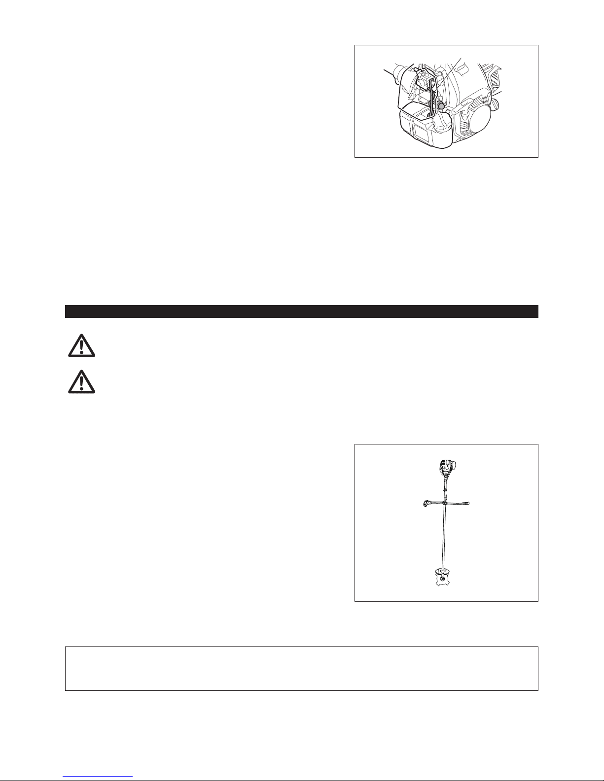
Designation of parts.......................................................8
Mounting of handle ........................................................9
Mounting of protector...................................................10
Mounting of metal blade or nylon cutting head ............12
Before start of operation ..............................................13
Correct handling of machine........................................15
Points in operation and how to stop ............................16
Resharpening the cutting tool ......................................18
Servicing instructions...................................................22
Storage ........................................................................25
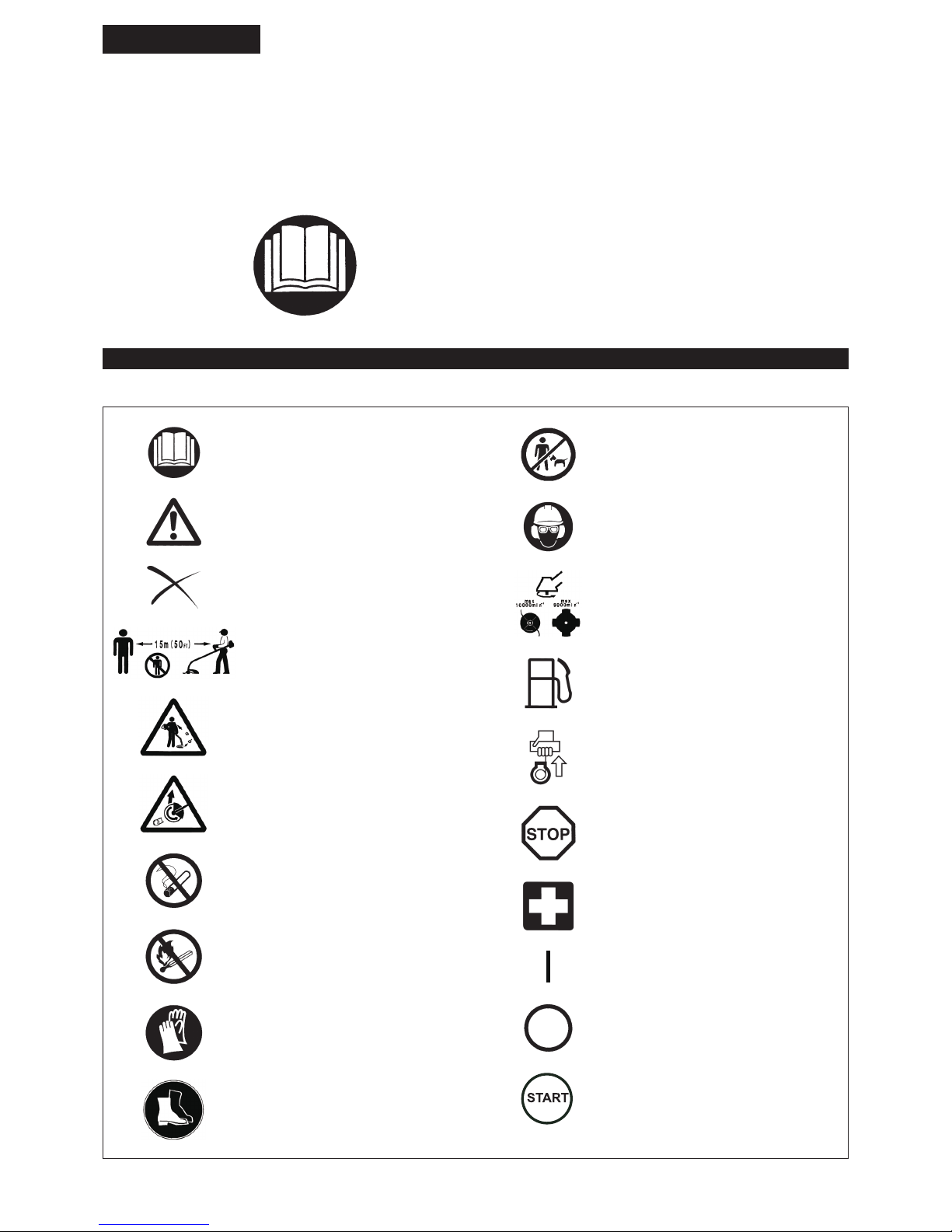
Read instruction manual and follow the
warnings and safety precautions!
Take Particular care and attention!
Forbidden!
Keep distance!
Flying object hazard!
Kickback!
No smoking!
No open ame!
Protective gloves must be worn!
Wear sturdy boots with nonslip soles.
Steeltoed safety boots are recommended!
Keep the area of operation clear of all
persons and pets!
Wear protective helmet, eye and ear
protection!
Top permissible tool speed
Fuel (Gasoline)
Engine-manual start
Emergency stop
First Aid
ON/START
OFF/STOP
THROTTLE LOCK POSITION
3
15 Meters
Diagrammatic gure
SAFETY INSTRUCTIONS
General Instructions
Read this instruction manual to become familiar with handling of the –
equipment. Users insufciently informed will risk danger to themselves as
well as others due to improper handling.
It is recommended only to lend the equipment to people who have proven to –
be experienced.
Always hand over the instruction manual.
First users should ask the dealer for basic instructions to familiarize oneself –
with the handling of brushcutters.
Children and young persons aged under 18 years must not be allowed to –
operate this equipment. Persons over the age of 16 years may however
use the device for the purpose of being trained while under supervision of a
qualied trainer.
Use with the utmost care and attention. –
Operate only if you are in good physical condition. Perform all work calmly –
and carefully. The user has to accept liability for others.
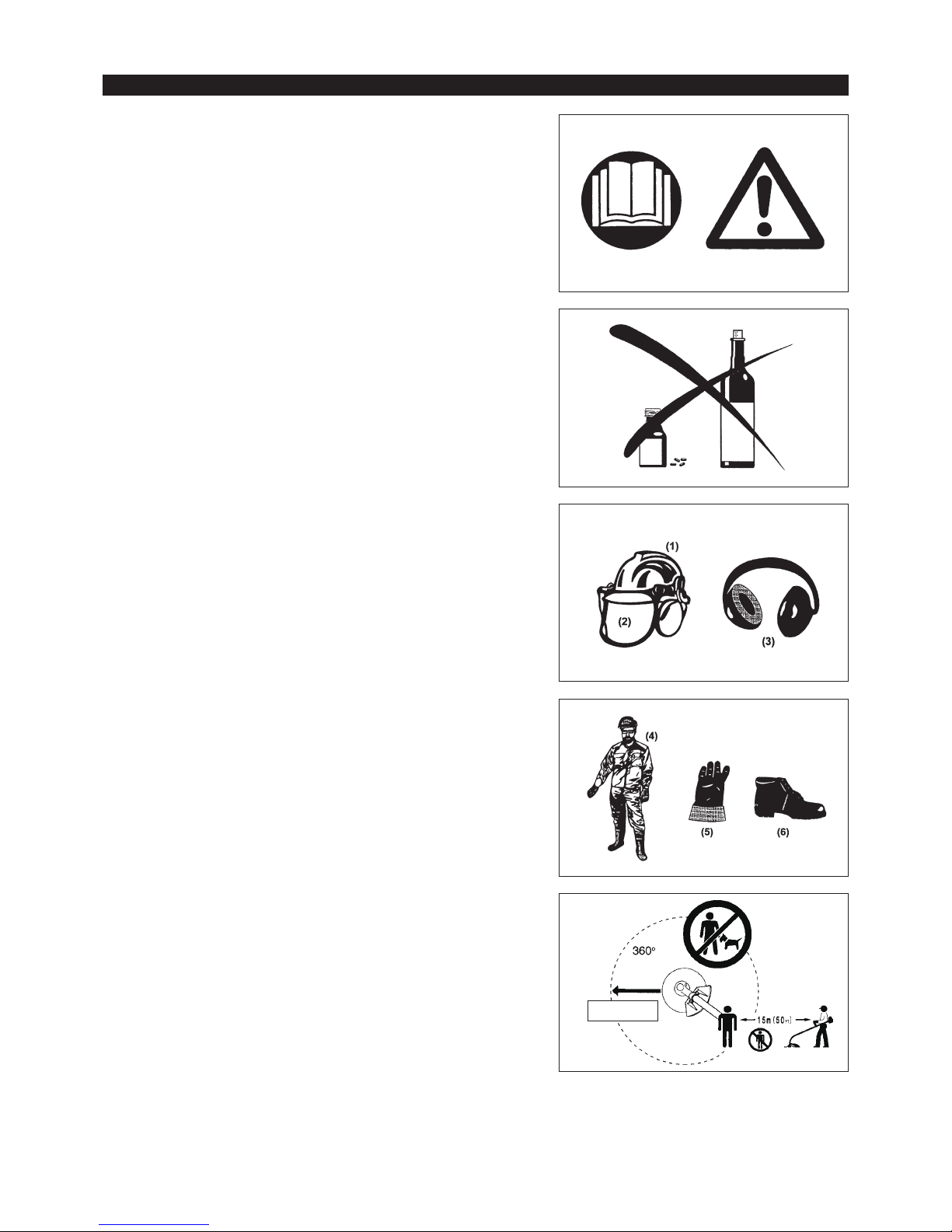
Never use this equipment after consumption of alcohol or drugs, or if feeling –
tired or ill.
National regulation can restrict the use of the machine. –
Intended use of the machine
This equipment is only intended for cutting grass, weeds, bushes, –
undergrowth. It should not be used for any other purpose such as edging or
hedge cutting as this may cause injury.
Personal protective equipment
The clothing worn should be functional and appropriate, i.e. it should be tight- –
tting but not cause hindrance. Do not wear either jewelry or clothing which
could become entangled with bushes or shrubs.
In order to avoid either head-, eye-, hand-or foot injuries as well as to protect –
your hearing the following protective equipment and protective clothing must
be used during operation.
Always wear a helmet where there is a risk of falling objects. The protective –
helmet (1) is to be checked at regular intervals for damage and is to be
replaced at the latest after 5 years. Use only approved protective helmets.
The visor (2) of the helmet (or alternatively goggles) protects the face from –
ying debris and stones. During operation always wear goggles, or a visor to
prevent eye injuries.
Wear adequate noise protection equipment to avoid hearing impairment (ear –
muffs (3), ear plugs etc.).
The work overalls (4) protect against ying stones and debris. –
We strongly recommend that the user wears work overalls.
Gloves (5) are part of the prescribed equipment and must always be worn –
during operation.
When using the equipment, always wear sturdy shoes (6) with a non-slip –
sole. This protects against injuries and ensures a good footing.
Starting up the brushcutter
Please make sure that there are no children or other people within a working –
range of 15 meters (50 ft), also pay attention to any animals in the working
vicinity.
Before use always check the equipment is safe for operation: –
Check the security of the cutting tool, the throttle lever for easy action and
check for proper functioning of the throttle lever lock.
Rotation of the cutting tool during idling speed is not allowed. Check with your –
dealer for adjustment if in doubt. Check for clean and dry handles and test
the function of the start/stop switch.
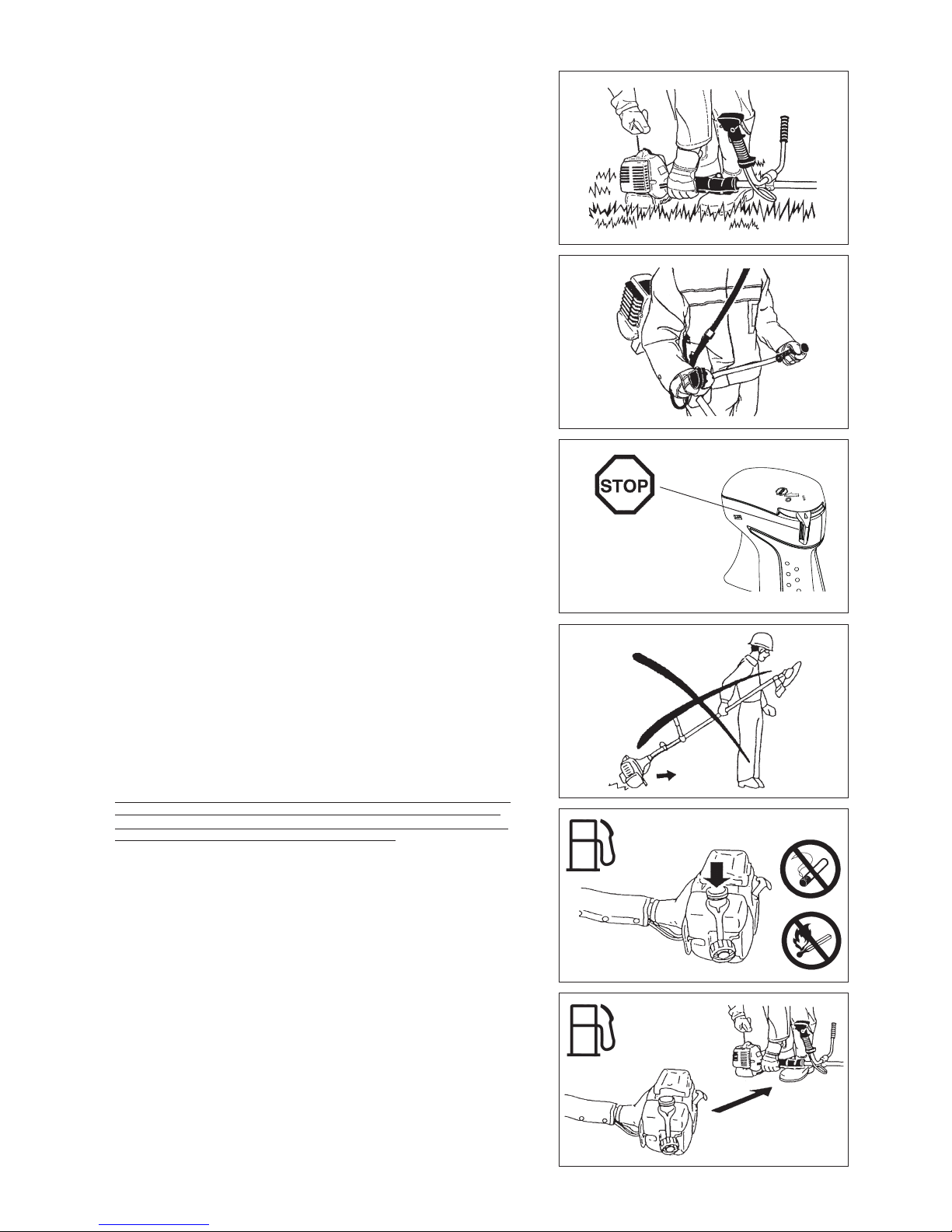
4
Resting•
Transport•
Refueling•
Maintenance•
Tool replacement•
3 meters
Start the brushcutter only in accordance with the instructions.
Do not use any other methods for starting the engine! –
Use the brushcutter and the tools only for such applications as specied. –
Only start the engine, after the entire assembly is done. Operation of the –
device is only permitted after all the appropriate accessories are attached!
Before starting make sure that the cutting tool has no contact with hard –
objects such as branches, stones etc. as the cutting tool will revolve when
starting.
The engine is to be switched off immediately in case of any engine problems. –
Should the cutting tool hit stones or other hard objects, immediately switch off –
the engine and inspect the cutting tool.
Inspect the cutting tool at short regular intervals for damage (detection of –
hairline cracks by means of tapping-noise test).
If the equipment gets heavy impact or fall, check the condition before –
continuing work. Check the fuel system for fuel leakage and the controls
and safety devices for malfunction. If there is any damage or doubt, ask our
authorized service center for the inspection and repair.
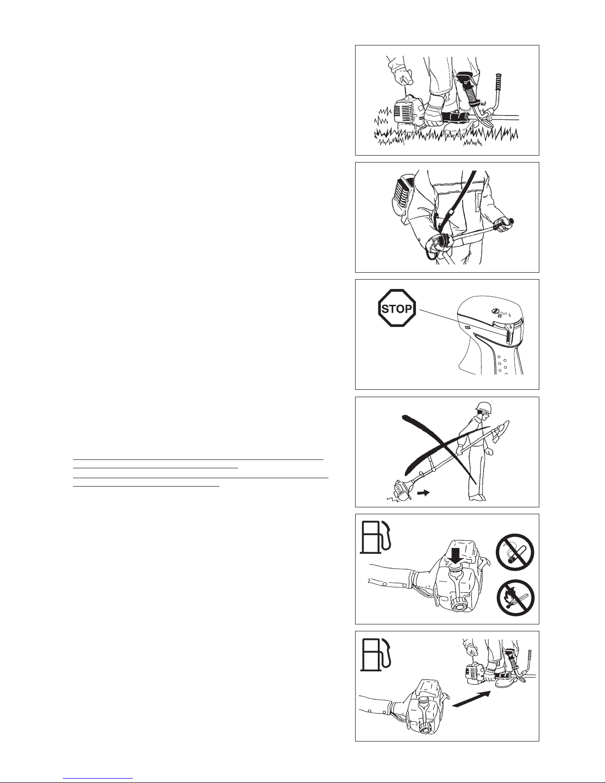
Operate the equipment only with the shoulder harness attached which is –
to be suitably adjusted before putting the brushcutter into operation. It is
essential to adjust the shoulder harness according to the user size to prevent
fatigue occurring during use. Never hold the cutter with one hand during use.
During operation always hold the brushcutter with both hands. –
Always ensure a safe footing.
Operate the equipment in such a manner as to avoid inhalation of the exhaust –
gases. Never run the engine in enclosed rooms (risk of gas poisoning).
Carbon monoxide is an odorless gas.
Switch off the engine when resting and when leaving the equipment –
unattended, and place it in a safe location to prevent danger to others or
damage to the machine.
Never put the hot brushcutter onto dry grass or onto any combustible –
materials.
Always install the approved cutting tool guard onto the equipment before –
starting the engine.
Otherwise contact with the cutting tool may cause serious injury.
All protective installations and guards supplied with the machine must be –
used during operation.
Never operate the engine with faulty exhaust mufer. –
Shut off the engine during transport. –
When transporting the equipment, always attach the cover to the metal blade. –
Ensure safe position of the equipment during car transportation to avoid fuel –
leakage.
When transporting, ensure that the fuel tank is completely empty. –
When unloading the equipment from the truck, never drop the Engine to the –
ground or this may severely damage the fuel tank.
Except in case of emergency, never drop or cast the equipment to the ground –
or this may severely damage the equipment.
Remember to lift the entire equipment from the ground when moving the –
equipment. Dragging the fuel tank is highly dangerous and will cause damage
and leakage of fuel, possibly causing re.
Refueling
Shut off the engine during refueling, keep away from open ames and do not –
smoke.
Avoid skin contact with mineral oil products. Do not inhale fuel vapor. Always –
wear protective gloves during refueling. Change and clean protective clothing
at regular intervals.
Take care not to spill either fuel or oil in order to prevent soil contamination –
(environmental protection). Clean the brushcutter immediately after fuel has
been spilt.
Avoid any fuel contact with your clothing. Change your clothing instantly if –
fuel has been spilt on it (to prevent clothing catching re).
Inspect the fuel cap at regular intervals making sure that it can be securely –
fastened and does not leak.
Carefully tighten the fuel tank cap. Change location to start the engine (at –
least 3 meters away from the place of refueling).
Never refuel in closed rooms. Fuel vapors accumulate at ground lever (risk of –
explosions).
Only transport and store fuel in approved containers. Make sure the fuel –
stored is not accessible to children.
5
Caution:
Kickback
Diagrammatic
gure
Diagrammatic
gure
Method of operation
Only use in good light and visibility. During the winter season beware of –
slippery or wet areas, ice and snow (risk of slipping). Always ensure a safe
footing.
Never cut above waist height. –
Never stand on a ladder. –
Never climb up into trees to perform cutting operation. –
Never work on unstable surfaces. –
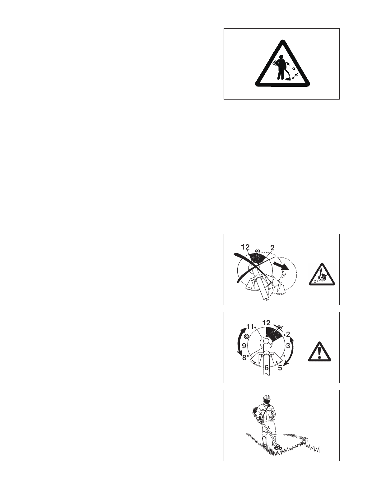
Remove sand, stones, nails etc. found within the working range. –
Foreign particles may damage the cutting tool and can cause dangerous
kick-backs.
Before commencing cutting, the cutting tool must have reached full working –
speed.
When using metal blades, swing the tool evenly in half-circle from right to left, –
like using a scythe.
If grass or branches get caught between the cutting tool and guard, always
stop the engine before cleaning. Otherwise unintentional blade rotation may
cause serious injury.
Take a rest to prevent loss of control caused by fatigue. We recommend to –
take a 10 to 20-minute rest every hour.
Cutting Tools
Use an applicable cutting tool for the job in hand. –
Nylon cutting heads (string trimmer heads) are suitable for trimming lawn
grass.
Metal blades are suitable for cutting weeds, high grasses, bushes, shrubs,
underwood, thicket, and the like.
Never use other blades including metal multi-piece pivoting chains and ail
blades. Otherwise serious injury may result.
When using metal blades, avoid “kickback” and always prepare for an –
accidental kickback. See the section “Kickback” and “Kickback prevention.”
Kickback (blade thrust)
Kickback (blade thrust) is a sudden reaction to a caught or bound metal –
blade. Once it occurs, the equipment is thrown sideway or toward the
operator at great force and it may cause serious injury.
Kickback occurs particularly when applying the blade segment between 12 –
and 2 o’clock to solids, bushes and trees with 3 cm or larger diameter.
To avoid kickback: –
Apply the segment between 8 and 11 o’clock;•
Never apply the segment between 12 and 2 o’clock;•
Never apply the segment between 11 and 12 o’clock and between 2 and •
5 o’clock, unless the operator is well trained and experienced and does it at
his/her own risk;
Never use metal blades close to solids, such as fences, walls, tree trunks •
and stones;
Never use metal blades vertically, for such operations as edging and •
trimming hedges.
Vibration
People with poor circulation who are exposed to excessive vibration may –
experience injury to blood vessels or the nervous system. Vibration may
cause the following symptoms to occur in the ngers, hands or wrists: “Falling
asleep” (numbness), tingling, pain, stabbing sensation, alteration of skin color
or of the skin. If any of these symptoms occur, see a physician!
To reduce the risk of “white nger disease”, keep your hands warm during –
operation and well maintain the equipment and accessories.
Maintenance instructions
Have your equipment serviced by our authorized service center, always using –
only genuine replacement parts. Incorrect repair and poor maintenance can
shorten the life of the equipment and increase the risk of accidents.
The condition of the cutter, in particular of the cutting tool of the protective –
devices and also of the shoulder harness must be checked before
commencing work. Particular attention is to be paid to the metal blades which
must be correctly sharpened.
Turn off the engine and remove spark plug connector when replacing or –
sharpening cutting tools, and also when cleaning the cutter or cutting tool.

6
Never straighten or weld damaged cutting tools.
Pay attention to the environment. Avoid unnecessary throttle operation for –
less pollution and noise emissions. Adjust the carburetor correctly.
Clean the equipment at regular intervals and check that all screws and nuts –
are well tightened.
Never service or store the equipment in the vicinity of naked ames. –
Always store the equipment in locked rooms and with an emptied fuel tank. –
When cleaning, servicing and storing the equipment, always attach the cover –
to the metal blade.
Observe the relevant accident prevention instructions issued by the relevant trade associations and by the insurance companies.
Do not perform any modications to the equipment as this will endanger your safety.
The performance of maintenance or repair work by the user is limited to those activities as described in the instruction manual. All other work is
to be done by an Authorized Service Agent. Use only genuine spare parts and accessories released and supplied by DOLMAR.
Use of non-approved accessories and tools means increased risk of accidents.
DOLMAR will not accept any liability for accidents or damage caused by the use of non-approved cutting tools and xing devices of cutting
tools, or accessories.
First Aid
In case of accident make sure that a rst-aid box is available in the vicinity of
the cutting operations. Immediately replace any item taken from the rst aid box.
When asking for help, please give the following
information:
Place of accident –
What happened –
Number of injured persons –
Kind of injuries –
Your name –
For European countries only
EC Declaration of Conformity
The undersigned, Tamiro Kishima and Rainer Bergfeld, as authorized by Dolmar GmbH, declare that the DOLMAR machine(s):
Designation of Machine: Petrol Brushcutter
Model No./ Type: MS-4300.4 U, MS-430.4 U, MS-430.4 C
Specications: see “TECHNICAL DATA” table
are of series production and
Conforms to the following European Directives:
2000/14/EC, 2006/42/EC
And are manufactured in accordance with the following standards or standardized documents:
EN ISO 11806-1
The technical documentation is on le at:
Dolmar GmbH,
Jenfelder Straße 38, Abteilung FZ, D-22045 Hamburg
The conformity assessment procedure required by Directive 2000/14/EC was in Accordance with annex V.
MS-4300.4 U:
Measured Sound Power Level: 111.9 dB
Guaranteed Sound Power Level: 113 dB
MS-430.4 U:
Measured Sound Power Level: 112.1 dB
Guaranteed Sound Power Level: 113 dB
MS-430.4 C:
Measured Sound Power Level: 110.7 dB
Guaranteed Sound Power Level: 112 dB
8. 9. 2011
Tamiro Kishima
Managing Director
Rainer Bergfeld
Managing Director

7
TECHNICAL DATA MS-4300.4 U, MS-430.4 U, MS-430.4 C
Model MS-4300.4 U MS-430.4 U MS-430.4 C
Handle type Bike handle Bike handle Loop handle
Dimensions: length x width x height (without cutting tool) mm 1,812 x 618 x 528 1,812 x 635 x 460 1,812 x 339 x 250
Mass (without plastic guard and cutting tool) kg 8.6 8.3 7.9
Volume (fuel tank) L 0.6
Volume (oil tank) L 0.1
Engine displacement cm
3
43.0
Maximum engine performance kW 1.5 at 7,500 min
-1
Engine speed at recommended max. spindle speed min
-1
10,500
Maximum spindle speed (corresponding) min
-1
7,200
Idling speed min
-1
3,000
Clutch engagement speed min
-1
4,000
Carburetor Diaphragm type
Ignition system Non-contact, magnet type
Spark plug type NGK CMR6A
Electrode gap mm 0.7 - 0.8
CUTTER
BLADE
NYLON
CUTTING
HEAD
CUTTER
BLADE
NYLON
CUTTING
HEAD
CUTTER
BLADE
NYLON
CUTTING
HEAD
Vibration per
ISO 22867
Right handle
(Rear grip)
a
hv eq
m/s
2
2.2 2.1 3.1 3.5 4.2 2.6
Uncertainty K m/s
2
0.5 0.6 0.5 0.8 1.1 0.7
Left handle
(Front grip)
a
hv eq
m/s
2
1.7 2.0 4.8 4.0 3.8 3.7
Uncertainty K m/s
2
0.5 0.5 2.9 0.9 1.0 1.4
Sound pressure level average to
ISO 22868
L
PA eq
dBA 92.4 96.2 91.2 96.1 92.8 94.9
Uncertainty K dBA 1.8 2.0 2.2 1.6 1.6 2.1
Sound power level average to
ISO 22868
L
WA eq
dBA 101.8 108.9 103.1 109.1 103.4 107.7
Uncertainty K dBA 1.8 1.4 1.1 1.1 1.5 1.2
Fuel Automobile gasoline (petrol)
Engine Oil
API grade SF class or higher, SAE 10W-30 oil
(automobile 4-stroke engine oil)
Cutting tools (cutter blade dia.) mm 305 (with three blades)
Gear ratio 13/19
8
MS-430.4 CMS-4300.4 U MS-430.4 U
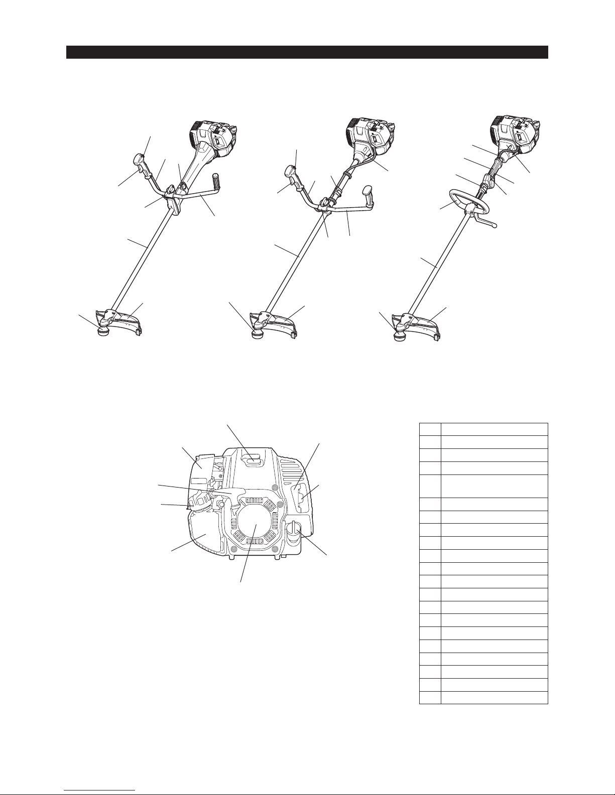
DESIGNATION OF PARTS
7
12
8
9
11
4
10
13
15
14
4
11
12
9
10
16
13
14
15
4
11
12
7
10
16
13
14
15
9
5
6
19
20
2
1
17
18
3
GB DESIGNATION OF PARTS
1 Fuel tank
2 Recoil starter
3 Air cleaner
4
I-O and throttle lock switch
(on/off)
5 Spark plug
6 Exhaust mufer
7 Clutch case
8 Rear grip
9 Hanger
10 Handle
11 Throttle lever
12 Control cable
13 Shaft
14 Protector (Cutting tool guard)
15 Gear Case/Head case
16 Handle holder
17 Fuel tank cap
18 Starter knob
19 Exhaust pipe
20 Oil cap
9
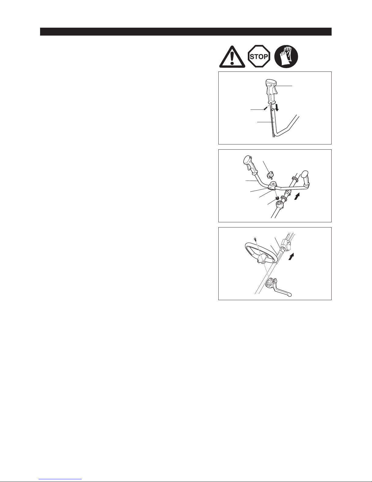
CAUTION: Before doing any work on the equipment, always stop the engine
and pull the spark plug connector off the spark plug.
Always wear protective gloves!
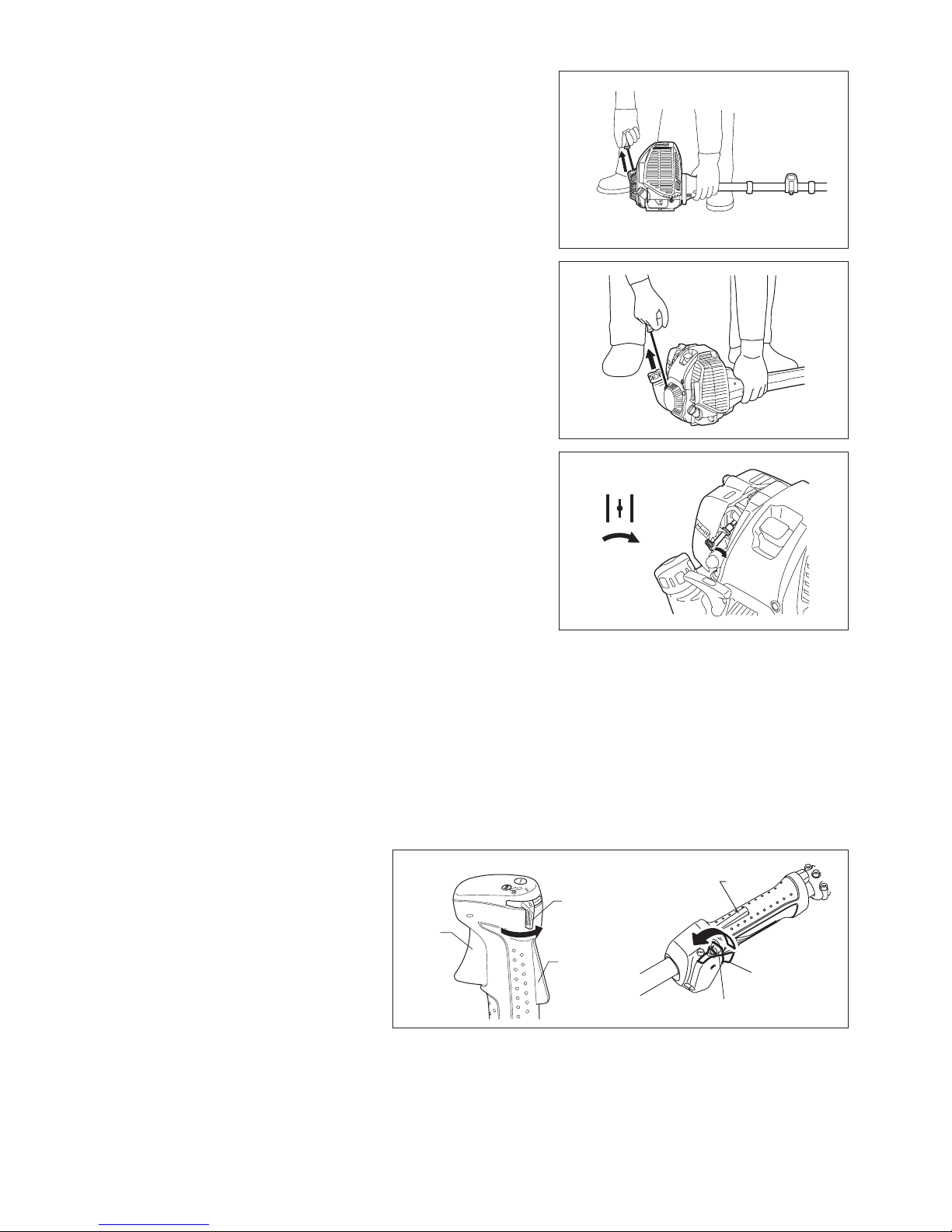
CAUTION: Start the engine only after having assembled it completely.
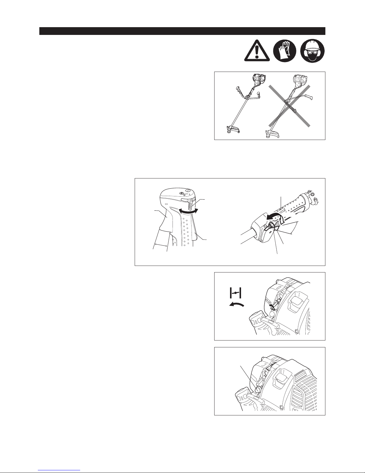
For model MS-4300.4 U, MS-430.4 U
Insert the shaft of the handle into the grip as shown.
Align the screw hole in the grip with the one in the shaft.
Tighten the screw securely.
MOUNTING OF HANDLE
Loosen knob (1). –
Place handle (4) between handle clamp (2) and handle holder (3). –
Adjust handle (4) to an angle that provides a comfortable working position –
and then secure by rmly hand-tightening knob (1).
CAUTION: Do not forget to mount spring (5).
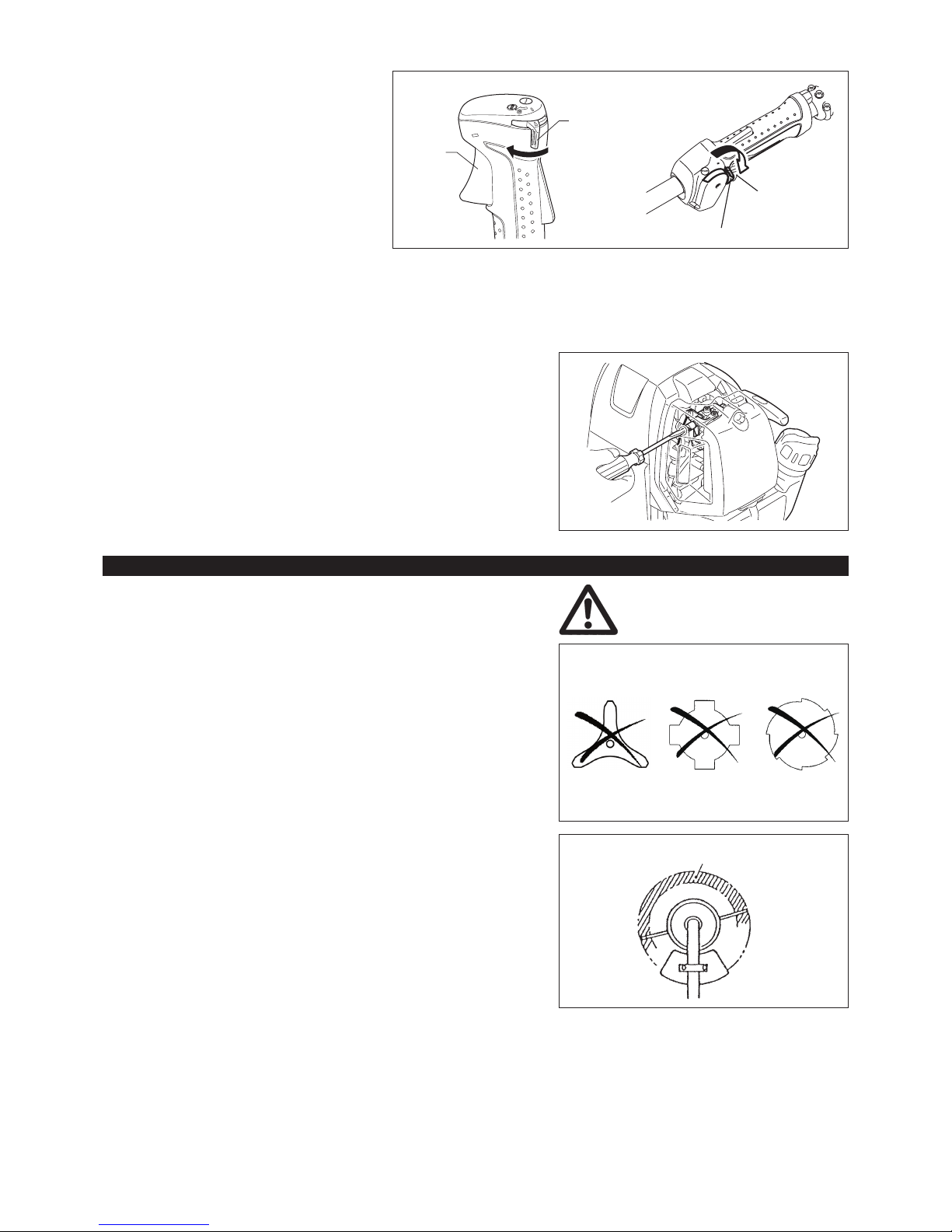
For model MS-430.4 C
Fix the loop handle on the shaft with four screws. –
To keep a proper distance between the grips, place the spacer (1) between –
the loop handle and the hanger (2).
(1)
(2)
(4)
(3)
(5)
(1)
(2)
Engine
Engine
Grip
Screw
Handle
10
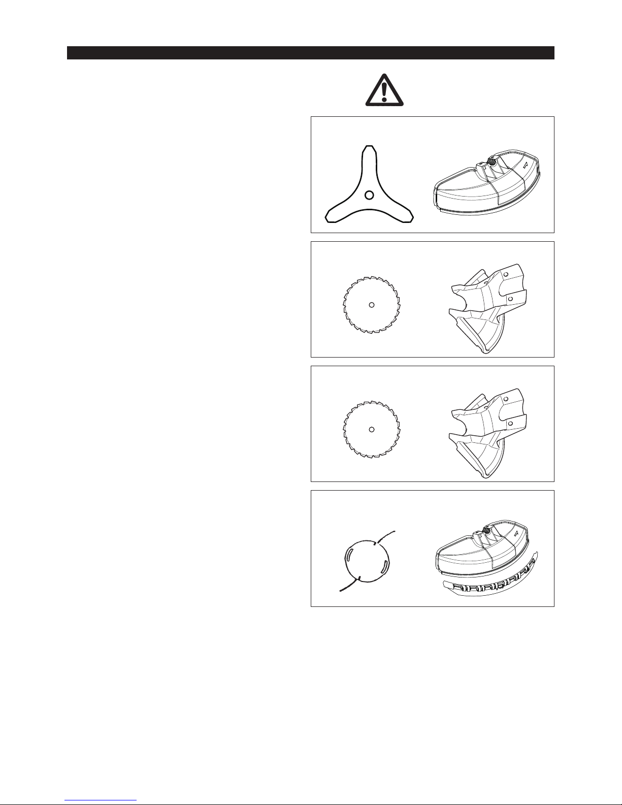
To meet the applicable safety provisions, only the tool/protector
combinations as indicated in the table must be used.
MOUNTING OF PROTECTOR
Be sure to use genuine DOLMAR metal blades (including
saw blade and cutter blade) or nylon cutting head.
The metal blade must be well polished, free of cracks or –
breakage. If the metal blade hits against a stone during
operation, stop the engine and check the blade immediately.
Polish or replace the metal blade every three hours of –
operation.
If the nylon cutting head hits against a stone during –
operation, stop the engine and check the nylon cutting head
immediately.
CAUTION: The appropriate protector must always be installed,
for your own safety and in order to comply with
accident prevention regulations.
Operation of the equipment without the guard being
in place is not permitted.
The outside diameter of the cutter blade must be
300 mm (12”) or smaller. Never use any blades
exceeding 300 mm (12”) in outside diameter.
Use 200 mm saw-blade protector only when using
200 mm saw-blade.
Use 225 mm saw-blade protector only when using
225 mm saw-blade.
Do not apply other combination when using saw-
blade.
NOTE: The standard combination of cutting tool differs from
county to country.
Cutter blade
200 mm saw blade
225 mm saw blade
Nylon cutting head
Protector for metal blades
Protector for
200 mm saw blade
Protector for 225 mm
saw blade
Protector for
nylon cutting head
11
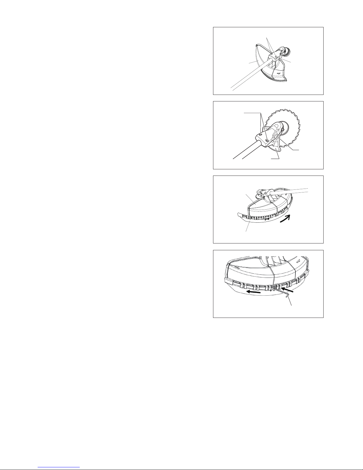
(3)
(4)
In cases where the nylon cord cutter is to be used, be sure to mount the –
nylon cord cutter protector (4) onto the metal blade protector (3).
Mount the nylon cord cutter protector (4) by sliding it into place from the ank –
of the metal blade protector (3) as shown.
Remove tape adhered to cutter, which cuts nylon cord, on nylon cord cutter –
protector (4).
CAUTION: Be sure to push in nylon cord cutter protector (4) until it is fully
inserted.
Take care not to injure yourself on the cutter for cutting the nylon
cord.
To remove the nylon cord cutter protector (4), apply a hex wrench into the –
notch on the metal blade protector (3), push it in and meanwhile slide the
nylon cord cutter protector (4).
Hex wrench
(3)
(2)
(1)
(1)
(2)
(3)
In use of the metal blade, x the protector (3) to the clamp (2) with two bolts –
(1).
NOTE: Tighten the right and left bolts evenly so that the gap between the clamp
(2) and the protector (3) will be constant.
Otherwise, the protector sometimes may not function as specied.
12
Be sure to use genuine DOLMAR metal blades or nylon
cutting head.
The metal blade must be well polished, free of cracks or breakage. If the –
metal blade hits against a stone during operation, stop the engine and check
the blade immediately.
Polish or replace the metal blade every three hours of operation. –
If the nylon cutting head hits against a stone during operation, stop the –
engine and check the nylon cutting head immediately.
CAUTION: The appropriate protector must always be installed, for your own
safety and in order to comply with accident-prevention regulations.
Operation of the equipment without the guard being in place is not
permitted.
The outside diameter of the cutter blade must be 300 mm (12”)
or less. Never use any blades exceeding 300 mm (12”) in outside
diameter.
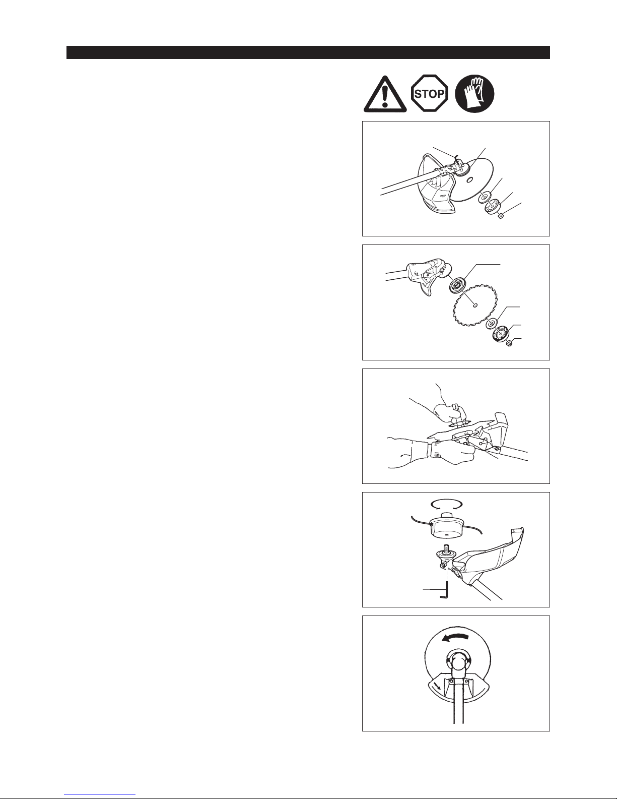
Turn the machine upside down, and you can replace the metal blade or nylon
cutting head easily.
Insert the hex wrench through the hole in the gear case and rotate the –
receiver washer (4) until it is locked with the hex wrench.
Loosen the nut (1) (left-hand thread) with the socket wrench and remove the –
nut (1), cup (2), and clamp washer (3).
(4)
(3)
(2)
(1)
(4)
(3)
(2)
(1)
Rotation
Hex wrench
MOUNTING OF METAL BLADE OR NYLON CUTTING HEAD
Mounting of metal blade with the hex wrench still in place
Mount the metal blade onto the shaft so that the guide of the receiver washer –
(4) ts in the arbor hole in the metal blade. Install the clamp washer (3), cup
(2), and secure the metal blade with the nut (1).
[Tightening torque: 20 - 30 N-m]
NOTE: Always wear gloves when handling the metal blade.
NOTE: The metal blade-fastening nut (with spring washer) is a consumable
part. If there appears any wear or deformation on the spring washer,
replace the nut.
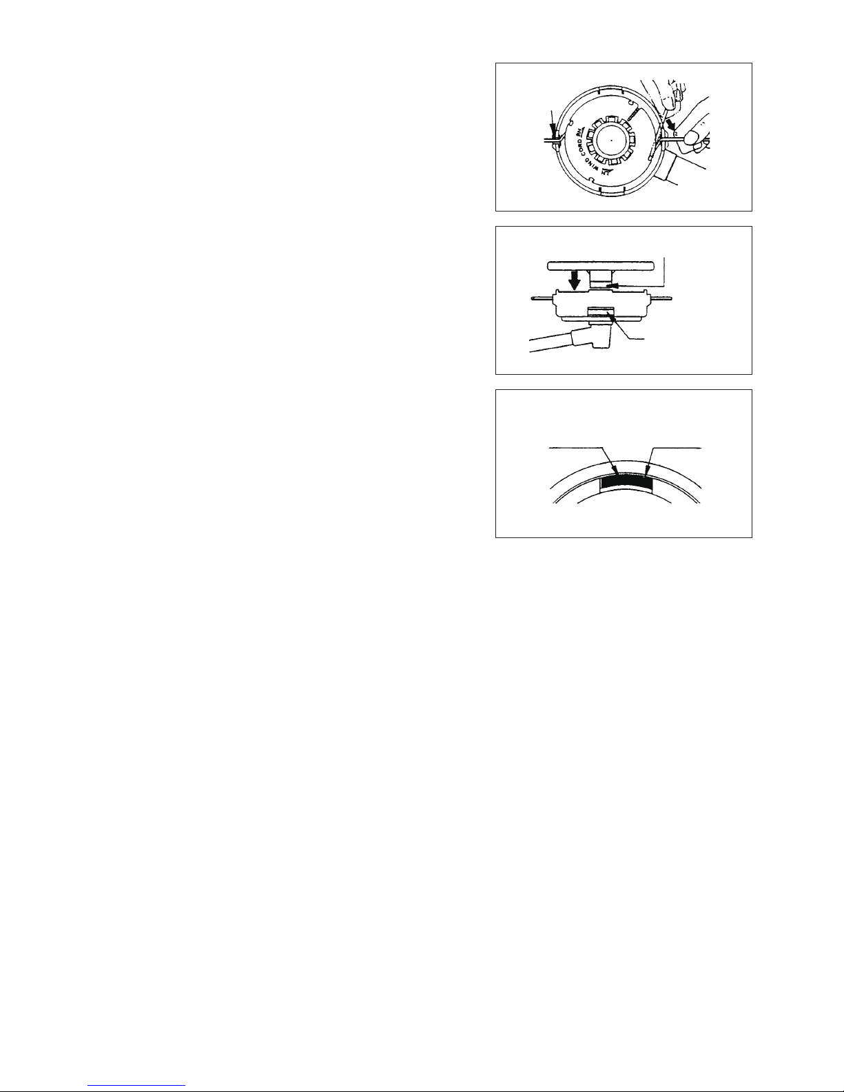
Mounting of nylon cutting head
The clamp washer (3), cup (2), and nut (1) are not necessary for mounting –
the nylon cutting head. The nylon cutting head should go on top of the
receiver washer (4).
Insert the hex wrench through the hole in the gear case and rotate the –
receiver washer (4) until it is locked with the hex wrench.
Then screw the nylon cutting head onto the shaft by turning it counter- –
clockwise.
Remove the hex wrench. –
Hex wrench
Loosen Tighten
Hex wrench
13
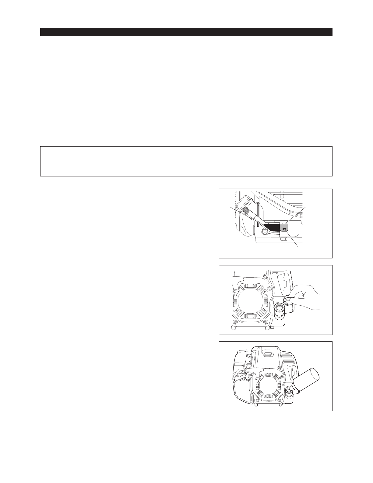
Inspection and rell of engine oil
Perform the following procedure, with the engine cooled down. –
Assure that the engine is on a at horizontal surface and conrm if the oil level is between the lower or upper limit of the oil indicator. –
If the oil level is below the lower limit, remove the oil cap and add oil. –
The area surrounding the external marks is transparent, so the amount of oil inside can be checked without having to remove the oil cap. –
However, if oil pipe becomes extremely dirty, visibility may be lost, and oil level will have to be checked against stepped section on inside of
oil pipe.
You may need to rell oil approximately every 10 operating hours (every 10 refuelings). –
If the oil changes in color or mixes with dirt, replace it with new one. (For the interval and method of replacement, refer to P 22.)
Recommended oil: SAE 10W-30 oil of API Classication, Class SF or higher (4-stroke engine for automobile)
Oil volume: Approx. 0.10L
NOTE: If the engine is not positioned as illustrated on a horizontal surface, an inaccurate indication of oil level may occur and oil may be
overlled. Filling oil above the upper limit may cause oil contamination and/or white smoke.
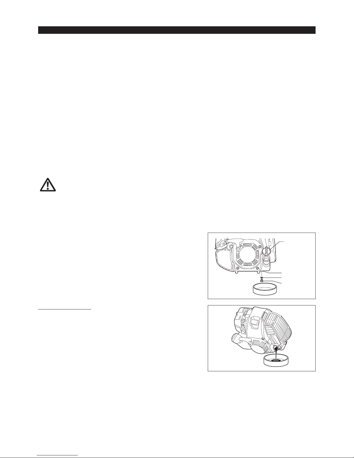
Replacement of oil: “Oil cap”
Remove dust or dirt near the oil rell port, and detach the oil cap. –
Keep the detached oil cap free of sand or dust. Otherwise, any sand or dust adhering to the oil cap may cause irregular oil circulation or –
wear on the engine parts, which will result in troubles.
BEFORE START OF OPERATION
(1) Keep the engine level, and detach the oil cap.
(2) Fill with oil to upper limit mark.
Use oil bottle when lling.
(3) Securely tighten the oil cap. Insufcient tightening may cause oil leakage.
Upper limit
Lower limit
Oil
14
Refueling
WARNING: Shut off the engine before refueling, keep away from
open ames and do not smoke.
Loosen the tank cap a little to release the tank pressure. –
Detach the tank cap, and refuel, discharging air by tilting the fuel tank so that –
the refuel port will be oriented upward. DO NOT ll fuel up to the top of the
tank.
Wipe the outside of the tank cap to prevent debris from entering into the fuel –
tank.
After refueling, securely tighten the tank cap. –
If there is any aw or damage on the tank cap, replace it.•
The tank cap wears out in course of time. Replace it every two to three years.•
DO NOT put fuel in the oil ll port.•
Fuel tank cap
Fuel upper limit
Fuel tank
Note
Do not replace oil with the engine in a tilted position.•
Filling with oil while engine is tilted leads to overlling which causes oil contamination and/or white smoke.•
After relling oil
Wipe with a rag any spilled oil immediately. –
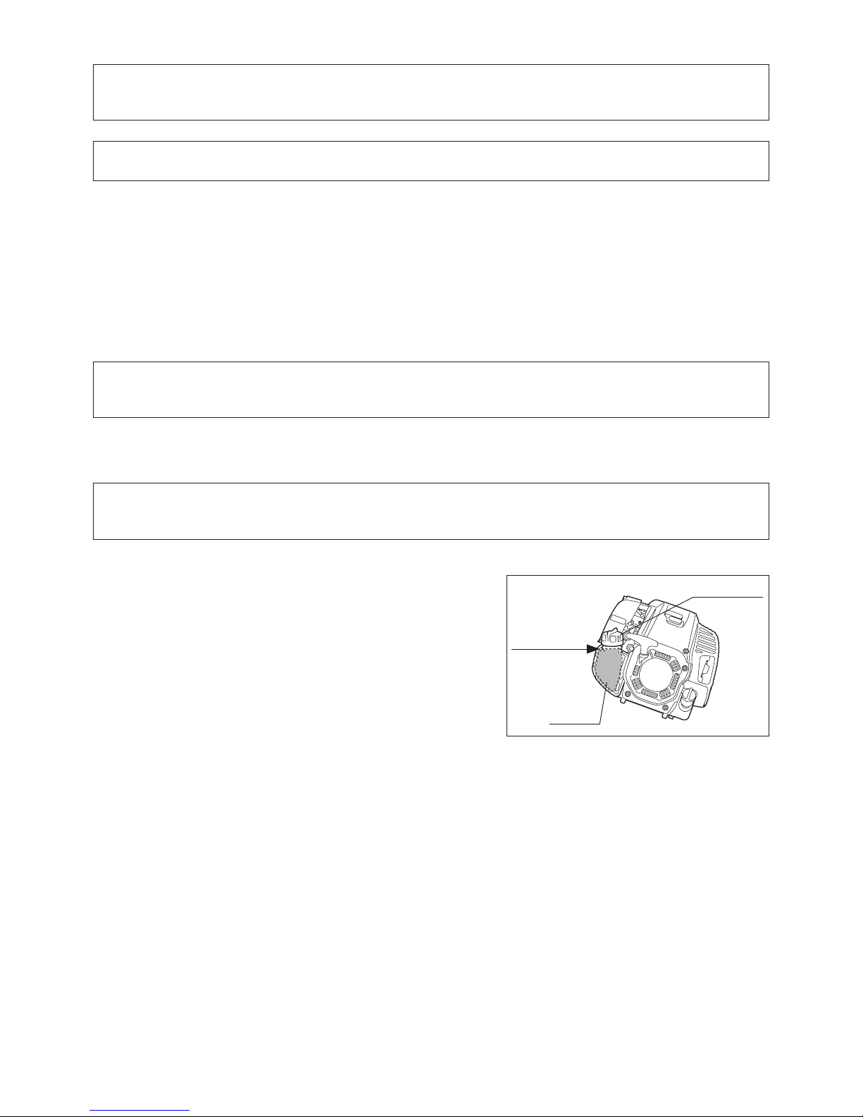
REFUELING
Handling of fuel
It is necessary to handle fuel with utmost care. Fuel may contain substances similar to solvents. Refueling must be performed in a sufciently
ventilated room or in the open air. Never inhale fuel vapor, and keep fuel away from you. If you touch fuel repeatedly or for a long time, the
skin becomes dry, which may cause skin disease or allergy. If fuel enters into the eye, clean the eye with fresh water. If your eye remains still
irritated, consult your doctor.
Storage period of fuel
Fuel should be used within a period of 4 weeks, even if it is kept in a special container in a well-ventilated and shaded area.
Otherwise, fuel may deteriorate in one day.
STORAGE OF MACHINE AND REFILL TANK
Keep the machine and tank at a cool place free from direct sunshine. –
Never keep the fuel in a car. –
Fuel
The engine is a four-stroke engine. Be sure to use an unleaded automobile gasoline 87 or higher octane ((R+M)/2). It may contain no more than
10% alcohol (E-10).
Points for fuel
Never use a gasoline mixture which contains engine oil. Otherwise, it will cause excessive carbon accumulation or mechanical troubles. –
Use of deteriorated oil will cause irregular start-up. –

15
CORRECT HANDLING OF MACHINE
Attachment of shoulder harness
Adjust the strap length so that the metal blade will be –
kept parallel with the ground.
For MS-4300.4 U, MS-430.4 U
Hold the harness on your back, attach it with the buckle,
and adjust the length of the bands.
NOTE: Be careful not to trap clothing, etc., in the buckle.
For MS-430.4 C
1) Stand as the band plate closer to you. And let your
arms and head pass through the band.
2) The band plate sits on your back and the adjustors and
hook comes on the right side of your body when you
appropriately equip the harness.
Hanger
2 kg max
Releasing the machine
For MS-4300.4 U, MS-430.4 U
To release the machine, squeeze the sides of the buckle (1) and take off the –
shoulder harness.
Be extremely careful to maintain control of the machine at this time. Do not
allow the machine to be deected toward you or anyone in the work vicinity.
WARNING: Failure to maintain complete control of the machine at all could
result in serious bodily injury or DEATH.
For MS-430.4 C
To release the machine, release the emergency detachment lever (2) by –
pulling strongly with ngers.
Be extremely careful to maintain control of the machine at this time. Do not
allow the machine to be deected toward you or anyone in the work vicinity.
WARNING: Failure to maintain complete control of the machine at all could
result in serious bodily injury or DEATH.
Hanging ring
For MS-4300.4 U
You can use the ring for hanging something weighing less than 2 kg (4.4 lbs). –
NOTICE: Do not hang anything weighing more than 2 kg(4.4 lbs) on the ring.
Anything heavier on the ring can cause it to fail and the item to be
damaged.
CAUTION: Do not hang anything on the ring that can become entangled with
bushes or shrubs. Entanglement can cause loss of balance and
control resulting in personal injury.
Buckle
(2)
MS-4300.4 U
MS-430.4 U
MS-4300.4 U
MS-430.4 U
MS-4300.4 U
MS-430.4 U
MS-4300.4 U
MS-430.4 C
(1)
Band plate
MS-430.4 C
16
Observe the applicable accident prevention regulations!
Before starting the engine, always set the handle in the proper position.
Otherwise the cutting tool may turn suddenly and cause injury, because the
throttle cable may be pulled or bent, and open the throttle.
STARTING
Move at least 3 m away from the place of refueling. Place the unit on the ground taking care that the cutting tool does not come into contact with
the ground or any other objects.
A: Cold start
1) Set this machine on a at space.
2) Set the I-O switch (1) to OPERATION.
POINTS IN OPERATION AND HOW TO STOP
MS-430.4 U
MS-4300.4 U
STOP
OPERATION
Lock-off
lever
High speed
Low speed
Throttle
lever
(1)
OPERATION
Lock-off lever
High speed
Low speed
Throttle lever
MS-430.4 C
STOP
(1)
3) Choke lever
Close the choke lever.
Choke opening:
- Full closing in cold or when the engine is cold.
- Full or half opening if the engine is a bit warm, such as restarting engine
just after stopping during warm-up operation.
4) Primer pump
Continue to push the primer pump until fuel comes into the primer pump. (In
general, 7 to 10 pushes.)
If the primer pump is pushed excessively, an excess of gasoline returns to
the fuel tank.
Primer pump
CLOSE
17
(1)
(2)
(3)
(3)
(1)
(2)
NOTE:
Do not pull the throttle lever unnecessarily when the engine is not running. It may cause ooding of fuel in the engine, and may cause the •
engine difcult to start up.
In case of ooding of the fuel, remove the spark plug and pull the starter handle slowly to remove excess fuel. Also, dry the electrode section •
of the spark plug.
If the engine res and stops, or stops soon after starting, return the choke lever to the OPEN position, and pull the starter knob a few times •
again to start the engine.
If the choke lever is left in the CLOSE position, and the starter knob merely pulled repeatedly, too much fuel will be sucked in, and the engine •
will become difcult to start.
Do not race the engine in warm-up operation unnecessarily.•
B: Warm start
1) Keep the choke lever full open.
2) Push the primer pump repeatedly.
3) Keep the throttle lever at the idling position.
4) Pull the recoil starter strongly.
5) If it is difcult to start the engine, release the
lock-off lever (3), pull the throttle lever (2), and
move the I-O switch (1) to the throttle lock
position. With holding the I-O switch (1), release
the throttle lever (2) and the lock-off lever (3).
Then pull the starter knob.
WARNING: Pay attention that the cutting tool
rotates immediately.
6) Once the engine starts, release the lock-off
lever (3) and pull the throttle lever (2), and
release them to make the engine idle.
OPEN
5) Recoil starter
Make sure you have a rm footing.
Hold the unit with your left hand and press it down rmly.
CAUTION: Do not stand or kneel on the throttle cable. The internal
wire may be pulled and the cutting tool may start rotating
unintentionally.
Do not open the throttle.
Pull the starter knob gently until a certain resistance is felt. Then, return the
starter knob, and pull it strongly.
Never pull the rope to the full extension. Once the starter knob is pulled,
never release your hand immediately. Hold the starter knob until it returns to
its original point.
6) Choke lever
Once engine starts, set choke lever to the OPEN position.
- Open the choke lever gradually while checking the engine operation. Be
sure to open the choke lever to the full in the end.
- In cold or when the engine is cooled down, never open the choke lever
suddenly. Otherwise the engine may stop.
7) Warm-up operation
Continue warm-up operation for 2 to 3 minutes.
NOTICE: Do not pull the throttle lever unnecessarily while the engine
is not running. It may cause fuel leak from the air cleaner. If it
happens, wipe leaked fuel off. Also, open the air cleaner cover
and clean the element and the air cleaner plate.
MS-430.4 U
MS-430.4 C
MS-4300.4 U
MS-430.4 U
MS-4300.4 U MS-430.4 C
18
CAUTION: The cutting tools shown in the illustration are not to be sharpened.
Manual resharpening will result in imbalances of the cutting tool
causing vibrations and damage to the equipment.
NOTE: To increase the service life of the cutter blade it may be turned over
once, until both cutting edges have become blunt.
RESHARPENING THE CUTTING TOOL
ADJUSTMENT OF IDLE SPEED
When it is necessary to adjust the idle speed, perform it by the carburetor adjusting screw.
CHECKUP OF IDLE SPEED
Set the idle speed to 3,000 min –
-1
.
If it is necessary to change the idle speed, use a phillips head screw driver on
the screw illustrated on the right.
To increase the idle speed, turn the adjusting screw clockwise. –
To reduce the idle speed, turn the adjusting screw counterclockwise.
The carburetor is factory adjusted. However, after several use the idle speed –
need to be re-adjusted.
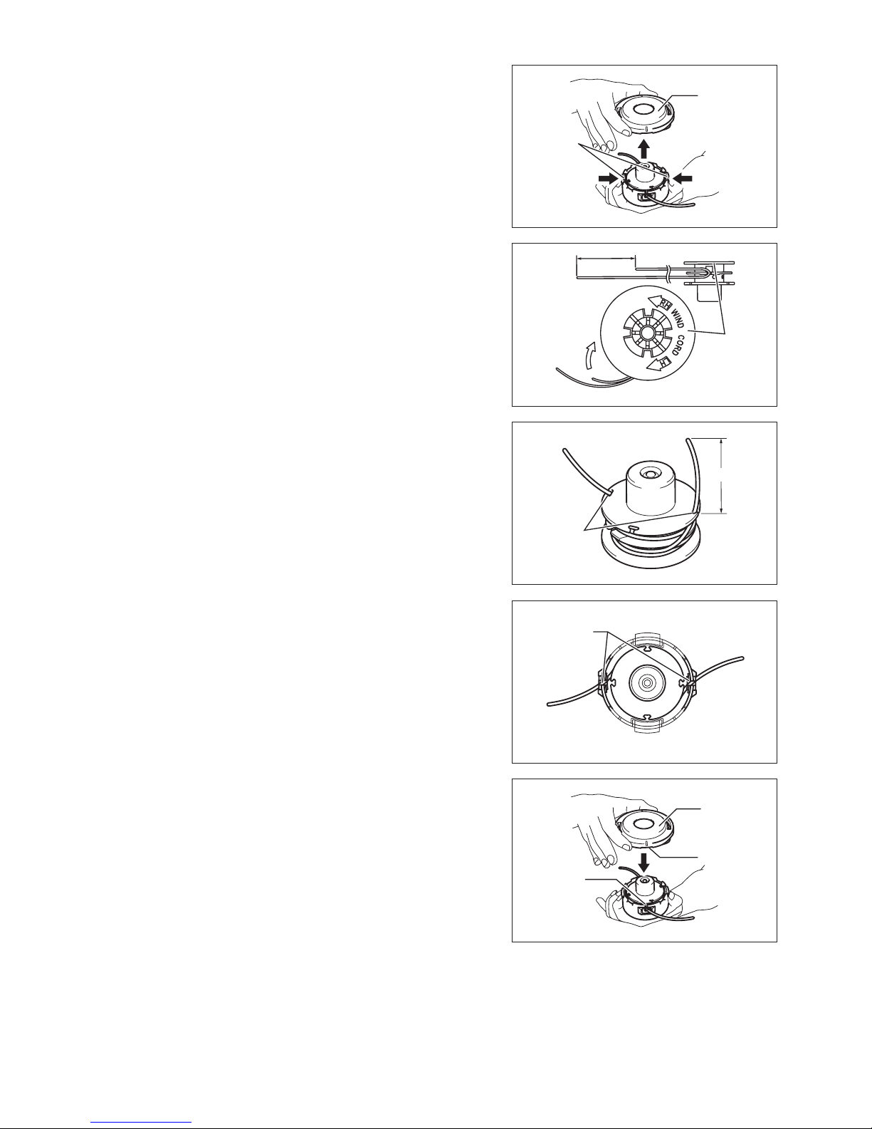
NYLON CUTTING HEAD
The nylon cutting head is a dual line trimmer head that has bump & feed
mechanism.
The nylon cutting head will feed out the proper length of nylon line after tapping
the nylon cutting head on the ground by changes in centrifugal force caused by
increasing or decreasing rpms.
Operation
Increase the nylon cutting head speed to approx. 6,000 min –
-1
.
Bump the nylon cutting head lightly on the ground.
The most effective cutting area is shown by the shaded area. –
If the nylon cord does not feed out, rewind/replace the nylon cord by following –
the procedures described under “Replacing the nylon cord.”
Most effective cutting area
STOPPING
1) Release the throttle lever (2) fully, and when the
engine rpm has lowered, set the I-O switch (1)
to STOP the engine will now stop.
2) The cutting tool continues to rotate a while
after stopping the engine. Wait until it stops
completely.
STOP
STOP
MS-430.4 U
MS-4300.4 U
(1)
(2)
MS-430.4 C
(1)
(2)
19
Replacing the nylon cord (BUMP & FEED)
WARNING: Make sure that the cover of the nylon cutting head is secured to
the housing properly as described below. Failure to properly secure
the cover may cause the nylon cutting head to y apart resulting in
serious personal injury.
Press inward on the housing latches and lift upward to remove the cover.
Discard any of the remaining nylon cord.
Hook the middle of the new nylon cord to the notch located at the center of the
spool between the 2 channels provided for the nylon cord. One side of the cord
should be about 80 mm longer than the other side.
Wind both ends rmly around the spool in the direction marked on the head for
left hand direction indicated by LH.
Wind all but about 100 mm of the cords, leaving the ends temporarily hooked
through a notch on the side of the spool.
Mount the spool in the housing so that the grooves and protrusions on the
spool match up with those in the housing. Keep the side with letters on the
spool visible on the top. Now, unhook the ends of the cord from their temporary
position and feed the cords through the eyelets to come out of the housing.
Align the protrusion on the underside of the cover with the slots of the eyelets.
Then push cover rmly onto the housing to secure it. Make sure the latches fully
spread in the cover.
Cover
Latches
Press Press
80 mm
For left hand
rotation
Spool
100 mm
Cover
Protrusion
Slot of
eyelet
Notches
Eyelets
20
notches
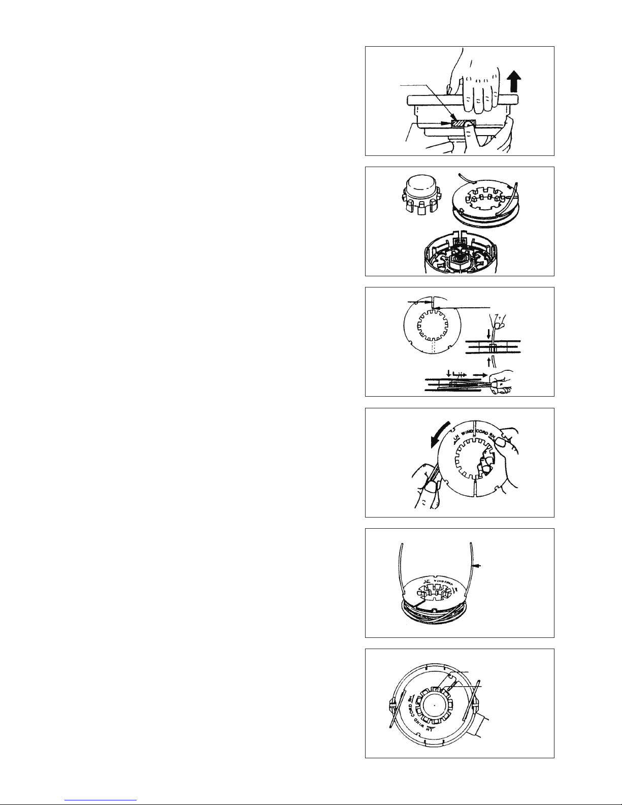
Replacing the nylon cord (ULTRA AUTO)
1. Put off cover from housing, pressing two cover locking tabs located oppositely
on side of the housing.
2. Take off tab knob and spool from the housing.
3. Put each one end of two cutting lines into each holes at innermost of the slot
on one of spool outer anges. Put the lines into spool gutters through each
slit on the anges.
4. Wind the lines up rmly to the direction slown by left-hand (LH) arrow on the
ange. Do not cross the lines.
5. Wind all but about 100 mm (3-15/16”) of the Cords, leaving the end
temporarily hooked through a notch on the side of the spool.
6. Put tab knob onto the housing hub, positioning it can freely move up and
down against spring tension. Put the spool into the housing, aligning the teeth
on spool and tap knob alternately like gears.
Pull up
Spool
There is a hole
innermost of the slit
To “LH” direction
100 mm from
notches
Tab knob’s teeth
Spool’s teeth
Wind tightly
Slit
Tab knob
Cover
locking
tab
21
7. Put in the cutting lines through the slot of eyelets.
8. Put the cover onto the housing, aligning the tabs on cover and the windows
on housing. Make sure the cover is secured exactly to the housing. Outer
edge of cover locking tab and outer surface of the housing should be on
same circumference.
Cover locking tab
Housing window
Outer
surface of
housing
Outer edge
of cover
locking tab
22
CAUTION: Before doing any work on the equipment, always stop the engine and pull the plug cap off the spark plug (see “checking the spark
plug”).
Always wear protective gloves!
To ensure a long service life and to avoid any damage to the equipment, the following servicing operations should be performed at regular
intervals.
Daily checkup and maintenance
Before operation, check the machine for loose screws or missing parts. Pay particular attention to the tightness of the metal blade or nylon –
cutting head.
Before operation, always check for clogging of the cooling air passage and the cylinder ns. –
Clean them if necessary.
Perform the following work daily after use: –
Clean the equipment externally and inspect for damage.•
Clean the air lter. When working under extremely dusty conditions, clean the lter the several times a day.•
Check the blade or the nylon cutting head for damage and make sure it is rmly mounted.•
Check that there is sufcient difference between idling and engagement speed to ensure that the cutting tool is at a standstill while the •
engine is idling (if necessary reduce idling speed).
If under idling conditions the tool should still continue to run, consult your nearest Authorized Service Agent.
Check the functioning of the I-O switch, the lock-off lever, the throttle lever, and the lock button. –
SERVICING INSTRUCTIONS
REPLACEMENT OF ENGINE OIL
Deteriorated engine oil will shorten the life of the engine. Be sure to check the oil and level regularly.
WARNING:
The engine and engine oil is still hot just after stopping engine. Allow sufcient time for the engine and engine oil to cool
down. Otherwise a skin burn may result.
NOTE: If the oil lled above the limit, it may be contaminated or may catch re with white smoke. Allow sufcient time after stopping
engine for the engine oil to return to the oil tank to ensure accurate reading of the oil level.
Interval of replacement: After rst 20 operating hours, followed by every 50 operating hours.
Recommended oil: SAE10W-30 oil of API Classication SF Class or higher (4-stroke engine oil for automobile)
In replacement, perform the following procedure.
1) Make sure that the fuel tank cap is tightened securely.
2) Place large container (pan, etc.) under drain hole.
3) Remove drain bolt and then remove oil cap to drain out oil from drain hole.
At this time, be sure not to lose drain bolt’s gasket, or get dirty any of the
removed components.
4) Once all the oil has been drained, install gasket and drain bolt, and tightly
secure drain bolt, so that it will not loosen and cause leaks.
[Tightening torque: 5 N-m]
* Use cloth to fully wipe off any oil attached to bolt and equipment.
Oil cap
Drain bolt
Gasket
Drain hole
Alternative draining method
Remove oil cap, tilt the equipment toward oil ller hole, and drain out oil.
Collect oil in container.
23
5) Set the engine level, and gradually ll up to upper limit mark with new oil.
6) After lling, tightly secure oil cap, so that it will not loosen and cause leaks.
If oil cap is not tightly secured, it may leak.
POINTS ON OIL
Never discard replaced engine oil in garbage, earth or sewage ditch. –
Disposal of oil is regulated by law. In disposal, always follow the relevant
laws and regulations. For any points remaining unknown, contact
Authorized Service Agent.
Oil will deteriorate even when it is kept unused. Perform inspection and –
replacement at regular intervals (replace with new oil every 6 months).
Plate
Element (sponge)
Air cleaner cover
Air cleaner cover
Element (sponge)
Separator plate
Element (paper)
Loop
Fixing bolt
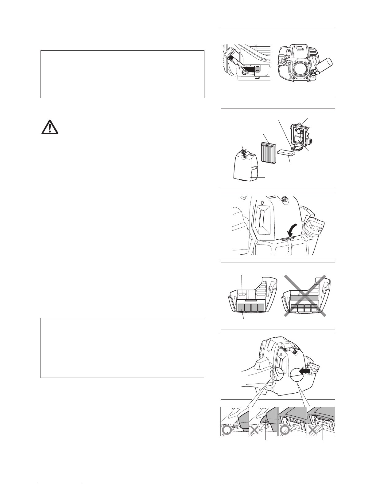
CLEANING OF AIR CLEANER
WARNING: Shut off the engine, keep away from open ames
and do not smoke.
Interval of Cleaning and Inspection: Daily (every 10 operating hours)
Turn the choke lever to the full close side, and keep the carburetor off from –
dust or dirt.
Removing air cleaner cover
Release the hook on the air cleaner cover by pressing down the loop on the –
plate.
Loosen xing bolt. –
Pull and remove the air cleaner cover. –
Cleaning element
Remove the elements and tap them to remove dirt. –
For heavy contamination: –
1) Remove the element (sponge), immerse it in warm water or in waterdiluted neutral detergent, and dry it completely. Do not squeeze or rub it
when washing.
2) Clean the element (paper) by tapping it gently. If you can use an air blow
gun, blow the compressed air onto the inside of the element (paper). Do
not wash the element (paper).
Before attaching the element (sponge), be sure to dry it completely. –
Insufcient drying of the element (sponge) may lead to difcult start-up.
Wipe out oil adhering around the air cleaner cover and separator plate with –
waste cloth.
Attaching air cleaner cover
Fit the element (sponge) and element (paper). Insert the element (sponge) all –
the way into the air cleaner cover.
Insert the side hook onto the air cleaner cover as illustrated, and push the –
lower part of the air cleaner cover until it clicks so that the hook sits into the
loop properly. And then tighten the air cleaner cover with xing bolt.
NOTICE:
Clean the elements several times a day, if excessive dust adheres to it. –
Dirty elements reduce engine power and make starting engine difcult.
Remove oil on the elements. If operation continues with the elements –
remaining not cleared of oil, oil in the air cleaner may fall outside, resulting
in contamination of the environment.
Do not put the elements on the ground or dirty place. Otherwise they pick –
up dirt or debris and it may damage the engine.
Never use fuel for cleaning the elements. Fuel may damage them. –
Side hook
Hook
24
0.7 mm - 0.8 mm
(0.028” - 0.032”)
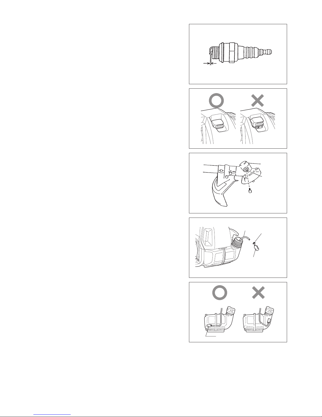
CHECKING THE SPARK PLUG
Only use the supplied universal wrench to remove or to install the spark plug. –
The gap between the two electrodes of the spark plug should be 0.7 - 0.8 mm –
(0.028” - 0.032”). If the gap is too wide or too narrow, adjust it. If the spark
plug is clogged or contaminated, clean it thoroughly or replace it.
Place the plug cap properly as illustrated after checking.
CAUTION: Never touch the spark plug connector while the engine is running
(danger of high voltage electric shock).
Gear case
Grease hole
SUPPLY OF GREASE TO GEAR CASE
Supply grease (Shell Alvania 2 or equivalent) to the gear case through the –
grease hole every 30 hours. (Genuine DOLMAR grease may be purchased
from your DOLMAR dealer.)
CLEANING OF FUEL FILTER
WARNING: INFLAMMABLES STRICTLY PROHIBITED
Interval of Cleaning and Inspection: Monthly (every 50 operating hours)
Suction head in the fuel tank
The fuel lter (1) of the suction head is used to lter the fuel required by the –
carburetor.
A periodical visual inspection of the fuel lter is to be conducted. Open the –
tank cap, use a wire hook and pull out the suction head through the tank
opening. If the lter is hard or clogged up, replace it.
Replace the fuel lter at least quarterly to ensure an enough fuel supply to the –
carburetor. Otherwise an insufcient fuel supply will cause the engine start
failure and limited maximum speed.
After checking, cleaning or replacing, x the fuel lter onto the fuel pipe with –
the hose clamp. Push the fuel lter in all the way to the bottom of the fuel
tank.
Fuel lter
Fuel pipe
Hose clamp
Fuel lter
25
Fuel pipe
REPLACEMENT OF FUEL PIPE
CAUTION: INFLAMMABLES STRICTLY PROHIBITED
Interval of Cleaning and Inspection: Daily (every 10 operating hours)
Replacement: Annually (every 200 operating hours)
Replace the fuel pipe every year, regardless of operating frequency. Fuel
leakage may lead to re.
If any leakage is detected during inspection, replace the fuel pipe immediately.
INSPECTION OF BOLTS, NUTS AND SCREWS
Retighten loose bolts, nuts, etc. –
Check the fuel cap and oil cap for tightness. Check for fuel and oil leakage. –
Replace damaged parts with new ones for safety operation. –
CLEANING OF PARTS
Always keep the engine clean by wiping down with a cloth rag. –
Keep the cylinder ns free of dust or dirt. Dust or dirt adhering to the ns will –
cause piston seizure.
REPLACEMENT OF GASKETS AND PACKINGS
Replace gaskets and packings if the engine is disassembled.
Any maintenance or adjustment work that is not included and described in this manual is only to be performed by Authorized Service Agents.
WARNING: The engine is still hot just after stopping engine. When draining the fuel, allow
sufcient time for the engine to cool down after stopping it. Otherwise a skin burn
and/or re may result.
DANGER: When the machine is kept out of operation for a long time, drain all fuel from the fuel
tank and carburetor, and keep it at a dry and clean place.
Drain fuel from the fuel tank and carburetor according to the following –
procedure:
1) Remove the fuel tank cap, and drain fuel completely.
If there is any foreign matter remaining in the fuel tank, remove it
completely.
2) Pull out the fuel lter from the rell port using a wire.
3) Push the primer pump until fuel is drained from there, and drain fuel
coming into the fuel tank.
4) Put the lter to the fuel tank, and securely tighten the fuel tank cap.
5) Then, continue to operate the engine until it stops.
Remove the spark plug, and drip several drops of engine oil through the –
spark plug hole.
Gently pull the starter handle so that engine oil will spread over the engine, –
and attach the spark plug.
Attach the cover to the metal blade. –
In general, store the machine in horizontal position, or if it is not possible, –
place the machine as the cutting tool comes below the engine. Pay full
attention how to store the machine to prevent the machine from falling.
Otherwise it may result in personal injury.
Keep the drained fuel in a special container in a well-ventilated shade. –
STORAGE
Attention after long-time storage
Before startup after long-time shutdown, be sure to replace oil (refer to P 22). Oil will deteriorate while the machine is kept out of –
operation.

26
Operating time
Item
Before
operation
After
refuleling
Daily
(10h)
30h 50h 200h
Before
storage
Corres-
ponding P
Engine oil
Inspect/clean
13
Replace
*
1
22
Tightening parts
(bolt, nut)
Inspect
24
Fuel tank
Clean/inspect
—
Drain fuel
*
3
25
Throttle lever Check function
—
Stop switch Check function
22
Cutting tool Inspect
10
Idle speed Inspect/adjust
18
Air cleaner Clean
23
Spark plug Inspect
24
Cooling air passage and
cylinder ns
Clean/inspect
25
Fuel pipe
Inspect
25
Replace
*
2
—
Gear-case grease Rell
24
Fuel lter Clean/replace
24
Valve clearance (intake valve
and exhaust valve)
Inspect/adjust
*
2
—
Carburetor Drain fuel
*
3
25
*1 Perform initial replacement after 20h operation.
*2 For the 200 operating hour inspection, request Authorized Service Agent or a machine shop.
*3 After emptying the fuel tank, continue to run the engine and drain fuel in the carburetor.

27
TROUBLESHOOTING
Before making a request for repairs, check for trouble by yourself. If any abnormality is found, control your machine according to the description
of this manual. Never tamper or dismount any part contrary to the description. For repairs, contact Authorized Service Agent or local dealership.
State of abnormality Probable cause (malfunction) Remedy
Engine does not start
I-O switch is set to STOP. Set the I-O switch to OPERATION.
Failure to operate primer pump Push 7 to 10 times
Low pulling speed of starter rope Pull strongly
Lack of fuel Feed fuel
Clogged fuel lter Clean
Broken fuel tube Straighten fuel tube
Deteriorated fuel Deteriorated fuel makes starting more difcult.
Replace with new fuel. (Recommended
replacement: 1 month)
Excessive suction of fuel Set throttle lever from medium speed to high
speed, and pull starter handle until engine
starts. Once engine starts, metal blade
starts rotating. Pay full attention to metal
blade.
If engine will not start still, remove spark plug,
dry the electrode, and reassemble them as
they originally are. Then, start as specied.
Detached plug cap Attach securely
Contaminated spark plug Clean
Abnormal clearance of spark plug Adjust clearance
Other abnormality of spark plug Replace
Abnormal carburetor Make request for inspection and maintenance.
Starter rope cannot be pulled Make request for inspection and maintenance.
Abnormal drive system Make request for inspection and maintenance.
Engine stops soon
Engine speed does not increase
Insufcient warm-up Perform warm-up operation
Choke lever is set to “CLOSE” although
engine is warmed up.
Set to “OPEN”
Clogged fuel lter Clean
Contaminated or clogged air cleaner Clean
Abnormal carburetor Make request for inspection and maintenance.
Abnormal drive system Make request for inspection and maintenance.
Metal blade does not rotate
Stop engine immediately
Loosened metal blade-tightening nut Tighten securely
Twigs caught by metal blade or dispersionpreventing cover.
Remove foreign matter
Abnormal drive system Make request for inspection and maintenance.
Main unit vibrates abnormally
Stop engine immediately
Broken, bent or worn metal blade Replace metal blade
Loosened metal blade-tightening nut Tighten securely
Shifted convex part of metal blade and metal
blade support tting.
Attach securely
Abnormal drive system Make request for inspection and maintenance.
Metal blade does not stop immediately
Stop engine immediately
High idling rotation Adjust
Detached throttle wire Attach securely
Abnormal drive system Make request for inspection and maintenance.
Engine does not stop
Run engine at idling, and set choke lever
to CLOSE
Detached connector Attach securely
Abnormal electric system Make request for inspection and maintenance.
When the engine does not start after warm-up operation:
If there is no abnormality found for the check items, open the throttle by about 1/3 and start the engine.

28
Дуже дякуємо Вам за покупку приводного інструмента для садовогородніх робіт DOLMAR. Ми раді рекомендувати Вам виріб DOLMAR, що
є результатом довготривалої програми розвитку та багаторічного знання й
досвіду.
Будь ласка, прочитайте цю брошуру, в ній детально описуються різні
вказівки щодо роботи інструмента, який продемонструє відмінні робочі
характеристики. Це допоможе Вам досягти найкращого результату
експлуатації Вашого виробу DOLMAR.
Зміст Сторінка
Під час читання цієї інструкції з експлуатації Ви зустрінете такі позначення.
ПОЗНАЧЕННЯ
Українська
(Оригінальні інструкції)
Позначення .................................................................28
Інструкції з техніки безпеки .......................................29
Технічні дані ...............................................................33
Позначення частин ....................................................34
Установлення ручки ...................................................35
Установлення захисного пристрою ...........................36
Установлення металевої пластини або ріжучої
головки з нейлоновим шнуром .................................38
Перед початком роботи ............................................. 39
Належне поводження з інструментом ......................41
Указівки щодо роботи та порядку зупинення ...........42
Заточування ріжучого інструмента ...........................44
Указівки щодо технічного обслуговування ...............48
Зберігання ..................................................................51
Ознайомтеся з цією інструкцією
з експлуатації та дотримуйтеся
застережень та заходів безпеки!
Будьте особливо уважні та обережні!
Заборонено!
Тримайте дистанцію!
Небезпека від предметів, що відлітають!
Віддача!
Не паліть!
Не використовуйте інструмент поблизу
відкритого вогню!
Надягайте захисні рукавиці!
Надягайте міцне взуття із підошвами,
що не ковзають.
Ми рекомендуємо захисне взуття зі
сталевим носком!
Не допускайте сторонніх осіб та
домашніх тварин до зони роботи!
Надягайте захисний шолом та засоби
захисту зору та слуху!
Гранична швидкість роботи інструмента
Паливо (бензин)
Ручний запуск двигуна
Аварійна зупинка
Перша допомога
УВІМКНЕННЯ/ПУСК
ВИМКНЕННЯ/ЗУПИНЕННЯ
ПОЛОЖЕННЯ БЛОКУВАННЯ
ПОСТАЧАННЯ ПАЛЬНОГО

29
Загальні положення
Прочитайте цю інструкцію з експлуатації, щоб ознайомитися з правилами –
поводження з інструментом. Недостатньо інформовані користувачі
піддають себе та оточуючих людей небезпеці через невірне поводження
з інструментом.
Використовувати інструмент дозволяється тільки особам, які є його –
досвідченими користувачами.
Із цим пристроєм слід завжди передавати й інструкцію.
Особи, які користуються цим інструментом уперше, повинні попросити –
дилера надати основні інструкції щодо належного поводження з
кущорізом.
Заборонено користуватися інструментом дітям та особам, яким не –
виповнилося 18 років. Разом з тим, особам, яким вже виповнилося 16,
дозволяється використовувати інструмент з навчальною метою, однак
під наглядом кваліфікованого інструктора.
Використовуйте інструмент із максимальною обережністю й увагою. –
Робота з інструментом дозволяється, тільки якщо Ви перебуваєте в –
гарній фізичній формі. Усю роботу виконуйте спокійно та обережно.
Користувач несе відповідальність за інших людей.
Ніколи не використовуйте цей інструмент після приймання ліків чи –
алкоголю або у разі втоми чи хворобливого стану.
Національні нормативи можуть обмежувати використання цього –
обладнання.
Використання інструмента за призначенням
Цей інструмент призначений виключно для скошування трави, бур'яну, –
кущів та підліска. Не дозволяється використовувати його за іншим
призначенням, наприклад, для окантовки та стриження живоплоту,
оскільки це може призвести до травм.
Засоби індивідуального захисту
Одяг, який Ви носите, повинен бути функціональним та відповідним, –
тобто він має щільно прилягати, проте не заважати роботі. Заборонено
надягати біжутерію або одяг, який може заплутатись у гілках або кущах.
Для запобігання травмам голови, очей, рук або ніг, а також для захисту –
органів слуху, під час роботи з інструментом слід використовувати засоби
захисту та захисний спецодяг, зазначені нижче.
Завжди надягайте захисний шолом, якщо є небезпека падіння предметів. –
Захисний шолом (1) слід регулярно перевіряти на наявність пошкоджень
та заміняти не рідше ніж через 5 років. Користуйтеся тільки дозволеними
захисними шоломами.
Захисна маска (2) шолому (або захисні окуляри) захищає обличчя від –
уламків та каміння, що розлітаються. Під час роботи завжди надягайте
захисні окуляри або захисну маску, щоб запобігти травмам очей.
Надягайте відповідні засоби захисту від шуму, щоб запобігти –
порушенням слуху (навушники (3), беруші тощо).
Робочий спецодяг (4) захищає від уламків та каміння, що відлітають. –
Ми наполегливо рекомендуємо надягати робочий спецодяг.
Рукавиці (5) є частиною відповідного захисного одягу, і їх обов'язково –
слід надягати кожного разу під час виконання робіт.
Використовуючи інструмент, завжди надягайте міцне взуття (6) з –
підошвами, що не ковзають. Це захистить Вас від травм та забезпечить
стійку опору на ноги.
Запуск кущоріза
Будь ласка, переконайтеся, що в радіусі 15 метрів (50 футів) немає дітей –
або сторонніх осіб, також слідкуйте за тваринами поблизу місця роботи.
Перед початком роботи завжди перевіряйте, щоб інструмент був у –
безпечному для роботи стані.
Перевіряйте також надійність закріплення ріжучого інструмента
та безперешкодну роботу важеля постачання пального, а також
перевіряйте, чи належним чином працює функція блокування важеля
постачання пального.
Забороняється обертання ріжучого інструмента на холостому ходу. Якщо –
у Вас виникнуть питання щодо налаштування, звертайтеся до Вашого
дилера. Перевіряйте, щоб ручки були чистими та сухими, після чого слід
перевіряти функціональність пускового перемикача.
15 метрів
Схематичне
зображення
ІНСТРУКЦІЇ З ТЕХНІКИ БЕЗПЕКИ
30
Запускайте кущоріз тільки відповідно до інструкцій.
Не використовуйте інші способи запуску двигуна! –
Використовуйте кущоріз та відповідні інструменти тільки за –
призначенням.
Запускайте двигун інструмента тільки після повного завершення –
збирання. Робота з інструментом дозволяється тільки після прикріплення
усього відповідного приладдя!
Перед початком роботи переконайтеся, що ріжучий інструмент не –
торкається твердих предметів, наприклад, гілля, каменів тощо, оскільки
під час пуску він обертатиметься.
У разі виникнення будь-яких проблем із двигуном його слід негайно –
вимикати.
Якщо ріжучій інструмент наштовхнувся на каміння або на інші тверді –
предмети, негайно вимкніть двигун та огляньте ріжучий інструмент.
Регулярно оглядайте ріжучий інструмент через короткі проміжки часу на –
наявність ушкоджень (виявляйте тонкі тріщини за допомогою шуму, що
має характер постукування).
Якщо інструмент зазнав серйозного удару або впав, перш ніж –
продовжувати роботу слід перевірити його стан. Перевіряйте паливну
систему на наявність витоку пального, а також належне функціонування
усіх важелів керування та засобів безпеки. Якщо Ви виявили
пошкодження або якщо у Вас виникли будь-які сумніви, звертайтеся
до нашого авторизованого сервісного центру для проведення огляду
інструмента та його ремонту.
Користуйтеся інструментом тільки з приєднаним плечовим ременем, –
який треба відповідним чином налаштувати, перш ніж запускати кущоріз.
Необхідно відрегулювати плечовий ремінь відповідно до фізичних
даних користувача, щоб запобігти появі утоми під час роботи. Ніколи не
тримайте інструмент під час роботи однією рукою.
Під час роботи завжди тримайте кущоріз обома руками. –
Постійно слідкуйте за надійною опорою ніг.
Використовуйте інструмент таким чином, щоб уникнути вдихання –
вихлопних газів. Ніколи не вмикайте двигун у закритому приміщенні
(небезпека отруєння газом). Чадний газ не має запаху.
Коли Ви відпочиваєте або залишаєте інструмент без нагляду, зупиняйте –
двигун та кладіть інструмент у безпечне місце, щоб запобігти небезпеці
інших осіб або пошкодженню інструмента.
Ніколи не кладіть гарячий кущоріз на суху траву або на поверхню із –
займистого матеріалу.
Перед запуском двигуна завжди встановлюйте захисний щиток ріжучого –
інструмента.
Інакше контакт із ріжучим інструментом може призвести до серйозних
травм.
Під час роботи необхідно використовувати всі захисні пристрої та щитки, –
що входять до комплекту інструмента.
Ніколи не користуйтеся двигуном із пошкодженим глушителем. –
Вимикайте двигун під час транспортування інструмента. –
Під час транспортування пристрою слід завжди приєднувати кришку до –
металевої пластини.
Задля запобігання витоку пального під час перевезень слідкуйте за –
безпечним розташуванням інструмента у транспортному засобі.
Перед перевезенням інструмента слід переконатися, що паливний бак –
порожній.
Під час знімання інструмента із транспортного засобу ніколи не кидайте –
двигун на землю, оскільки це може серйозно пошкодити паливний бак.
Крім аварійних випадків, ніколи не роняйте та не кидайте інструмент на –
землю, оскільки це може серйозно пошкодити його.
Під час переміщення не забувайте повністю піднімати інструмент із –
землі. Волочіння паливного баку є небезпечним і призведе до його
пошкодження та витоку пального, що може спричинити пожежу.
Заправляння
Під час заправляння вимикайте двигун та тримайтеся подалі від –
відкритого вогню і не паліть.
Уникайте контакту шкіри із мінеральними нафтопродуктами. Не вдихайте –
випаровування пального. Під час заправляння завжди надягайте захисні
рукавиці. Регулярно замінюйте та чистьте захисний одяг.
Будьте обережні, щоб не розлити пальне або мастило, оскільки це –
призведе до забруднення ґрунту (захист довкілля). Якщо Ви розлили
пальне на кущоріз, одразу ж очистіть його.
Уникайте контакту пального з одягом. Негайно замінюйте одяг, якщо на –
нього потрапило пальне (щоб запобігти займанню одягу).
Регулярно перевіряйте кришку паливного баку, аби переконатися, що –
вона надійно закривається та не пропускає рідину.
Надійно затягуйте кришку паливного баку. Перед увімкненням –
двигуна переходьте в інше місце (щонайменше на 3 метри від місця
заправляння).
Ніколи не заправляйте інструмент у закритому приміщенні. –
Випаровування пального збираються на рівні підлоги (небезпека вибуху).
Перевозіть та зберігайте пальне у відповідних контейнерах. Слідкуйте за –
тим, щоб діти не мали доступу до пального, яке Ви зберігаєте.
Відпочинок•
Транспортування•
Заправляння•
Технічне •
обслуговування
Заміна частин•
3 метри
 Loading...