


Original Instruction Manual
Instructions d’emploi d’origine
Originalbetriebsanleitung
Manuale di istruzioni originale
Originele gebruiksaanwijzing
Instrucciones de manejo originales
Instruções de serviço original
Original brugsanvisning
Πρωτότυπο εγχειρίδιο οδηγιών
Orijinal Kullanım Kılavuzu
Important:
Read this instruction manual carefully before putting the brushcutter into operation and strictly observe the safety regulations!
Preserve instruction manual carefully!
Important :
Veuillez lire attentivement ce manuel d’instructions avant d’utiliser la débroussailleuse et respectez rigoureusement les consignes de sécurité !
Veillez à conservez ce manuel d’instructions !
Wichtig:
Lesen Sie vor Verwendung der Motorsense diese Betriebsanleitung aufmerksam durch und halten Sie die Sicherheitsbestimmungen strikt ein!
Bewahren Sie diese Betriebsanleitung sorgfältig auf!
Importante:
Leggere attentamente il presente manuale di istruzioni prima di mettere in funzione il decespugliatore e rispettare scrupolosamente le norme
per la sicurezza.
Conservare con cura il manuale di istruzioni.
Belangrijk:
Lees deze gebruiksaanwijzing aandachtig door voordat u de bosmaaier in gebruik neemt en houdt u te allen tijde aan de veiligheidsinstructies!
Bewaar deze gebruiksaanwijzing zorgvuldig!
Importante:
Lea atentamente este manual de instrucciones antes de utilizar la desbrozadora y cumpla estrictamente la normativa de seguridad.
Conserve el manual de instrucciones con cuidado.
Importante:
Leia cuidadosamente este manual de instruções antes de utilizar a roçadeira e cumpra todas as normas de segurança!
Guarde este manual de instruções num local seguro!
Vigtigt:
Læs denne brugsanvisning omhyggeligt igennem inden du anvender buskrydderen og overhold sikkerhedsbestemmelserne til mindste detalje!
Gem denne brugsanvisning omhyggeligt!
Σημαντικό:
Πριν θέσετε σε λειτουργία τον θαμνοκοπτικό διαβάσετε προσεχτικά το παρόν εγχειρίδιο οδηγιών και εφαρμόσετε αυστηρά τους κανονισμούς
ασφαλείας.
Διατηρήστε με προσοχή το εγχειρίδιο οδηγιών!
Önemli:
Yan tırpanı kullanmaya başlamadan önce bu kullanım kılavuzunu dikkatlice okuyun ve güvenlik talimatlarını haryen takip edin!
Kullanım kılavuzunu dikkatlice saklayın!
MS-4215

Thank you very much for selecting the DOLMAR brushcutter. We are pleased to be
able to offer you the DOLMAR brushcutter which is the result of a long development
programme and many years of knowledge and experience.
Please read, understand and follow this booklet which refers in detail to the various
points that will demonstrate its outstanding performance. This will assist you to
obtain the best possible result from your DOLMAR brushcutter.
Table of Contents Page
Symbols .........................................................................2
Safety instructions .........................................................3
Technical data ...............................................................7
Designation of parts.......................................................8
Assembly of engine and shaft .......................................9
Mounting of handle ........................................................9
Mounting of protector...................................................10
Mounting of cutter blade or nylon cutting head............12
Fuels/refuelling ............................................................13
Correct handling of machine........................................14
Putting into operation...................................................15
Resharpening the cutting tool ......................................16
Maintenance schedule.................................................20
Storage ........................................................................21
You will note the following symbols when reading the instruction manual.
Read instruction manual and follow the
warnings and safety precautions!
Keep the area of operation clear of all
persons and pets
Take particular care and attention
Wear protective helmet, eye and ear
protection
Forbidden Top permissible tool speed
Keep distance Fuel and oil mixture
Flying object hazard Engine-Manual start
No smoking Emergency stop
No open flame First Aid
Protective gloves must be worn ON/START
Wear sturdy boots with non-slip
soles. Steel toed safety boots are
recommended.
OFF/STOP
Kickback
SYMBOLS
English
(Original instructions)
2
(1)
(3)
(2)
(4)
(5)
(6)
15m(50FT)
360
SAFETY INSTRUCTIONS
3
General Instructions
Read this instruction manual to become familiar with handling of the equipment. –
Users insufficiently informed will risk danger to themselves as well as others due
to improper handling.
It is recommended only to lend the equipment to people who have proven to be –
experienced.
Always hand over the instruction manual.
First users should ask the dealer for basic instructions to familiarize oneself with –
the handling of brushcutters.
Children and young persons aged under 18 years must not be allowed to operate –
this equipment. Persons over the age of 16 years may however use the device for
the purpose of being trained while under supervision of a qualified trainer.
Use with the utmost care and attention. –
Operate only if you are in good physical condition. Perform all work calmly and –
carefully. The user has to accept liability for others.
Never use this equipment after consumption of alcohol or drugs, or if feeling tired –
or ill.
National regulation can restrict the use of the machine. –
Intended use of the machine
This equipment is only intended for cutting grass, weeds, bushes, undergrowth. It –
should not be used for any other purpose such as edging or hedge cutting as this
may cause injury.
Personal protective equipment
The clothing worn should be functional and appropriate, i.e. it should be tight- –
fitting but not cause hindrance. Do not wear either jewelry or clothing which could
become entangled with bushes or shrubs.
In order to avoid either head-, eye-, hand-or foot injuries as well as to protect your –
hearing the following protective equipment and protective clothing must be used
during operation.
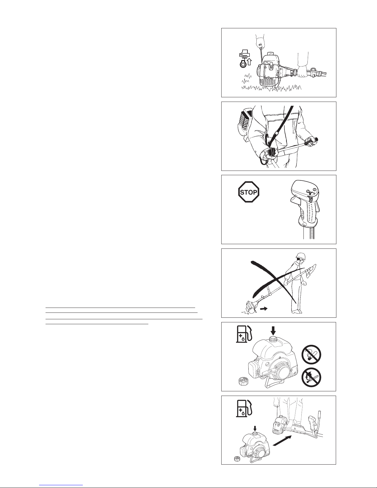
Always wear a helmet where there is a risk of falling objects. The protective –
helmet (1) is to be checked at regular intervals for damage and is to be replaced
at the latest after 5 years. Use only approved protective helmets.
The visor (2) of the helmet (or alternatively goggles) protects the face from flying –
debris and stones. During operation always wear goggles, or a visor to prevent
eye injuries.
Wear adequate noise protection equipment to avoid hearing impairment (ear –
muffs (3), ear plugs etc.).
The work overalls (4) protect against flying stones and debris. –
We strongly recommend that the user wears work overalls.
Gloves (5) are part of the prescribed equipment and must always be worn during –
operation.
When using the equipment, always wear sturdy shoes (6) with a non-slip sole. –
This protects against injuries and ensures a good footing.
Starting up the brushcutter
Please make sure that there are no children or other people within a working –
range of 15 meters (50 ft), also pay attention to any animals in the working
vicinity.
Before use always check the equipment is safe for operation: –
Check the security of the cutting tool, the throttle lever for easy action and check
for proper functioning of the throttle lever lock.
Rotation of the cutting tool during idling speed is not allowed. Check with your –
dealer for adjustment if in doubt. Check for clean and dry handles and test the
function of the start/stop switch.
Diagrammatic gure
15 Meters
Resting•
Transport•
Refuelling•
Maintenance•
Tool Replacement•
3 meters (10 ft)
4
Start the brushcutter only in accordance with the instructions.
Do not use any other methods for starting the engine! –
Use the brushcutter and the tools only for such applications as specified. –
Only start the engine, after the entire assembly is done. Operation of the device is –
only permitted after all the appropriate accessories are attached!
Before starting make sure that the cutting tool has no contact with hard objects –
such as branches, stones etc. as the cutting tool will revolve when starting.
The engine is to be switched off immediately in case of any engine problems. –
Should the cutting tool hit stones or other hard objects, immediately switch off the –
engine and inspect the cutting tool.
Inspect the cutting tool at short regular intervals for damage (detection of hairline –
cracks by means of tapping-noise test).
If the equipment gets heavy impact or fall, check the condition before continuing –
work. Check the fuel system for fuel leakage and the controls and safety devices
for malfunction. If there is any damage or doubt, ask our authorized service center
for the inspection and repair.
Operate the equipment only with the shoulder harness attached which is to be –
suitably adjusted before putting the brushcutter into operation. It is essential
to adjust the shoulder harness according to the user size to prevent fatigue
occurring during use. Never hold the cutter with one hand during use.
During operation always hold the brushcutter with both hands. –
Always ensure a safe footing.
Operate the equipment in such a manner as to avoid inhalation of the exhaust –
gases. Never run the engine in enclosed rooms (risk of gas poisoning). Carbon
monoxide is an odorless gas.
Switch off the engine when resting and when leaving the equipment unattended, –
and place it in a safe location to prevent danger to others or damage to the
machine.
Never put the hot brushcutter onto dry grass or onto any combustible materials. –
Always install the approved cutting tool guard onto the equipment before starting –
the engine.
Otherwise contact with the cutting tool may cause serious injury.
All protective installations and guards supplied with the machine must be used –
during operation.
Never operate the engine with faulty exhaust muffler. –
Shut off the engine during transport. –
When transporting the equipment, always attach the cover to the metal blade. –
Ensure safe position of the equipment during car transportation to avoid fuel –
leakage.
When transporting, ensure that the fuel tank is completely empty. –
When unloading the equipment from the truck, never drop the Engine to the –
ground or this may severely damage the fuel tank.
Except in case of emergency, never drop or cast the equipment to the ground or –
this may severely damage the equipment.
Remember to lift the entire equipment from the ground when moving the –
equipment. Dragging the fuel tank is highly dangerous and will cause damage
and leakage of fuel, possibly causing fire.
Refuelling
Shut off the engine during refuelling, keep away from open flames and do not –
smoke.
Avoid skin contact with mineral oil products. Do not inhale fuel vapor. Always –
wear protective gloves during refuelling. Change and clean protective clothing at
regular intervals.
Take care not to spill either fuel or oil in order to prevent soil contamination –
(environmental protection). Clean the brushcutter immediately after fuel has been
spilt.
Avoid any fuel contact with your clothing. Change your clothing instantly if fuel –
has been spilt on it (to prevent clothing catching fire).
Inspect the fuel cap at regular intervals making sure that it can be securely –
fastened and does not leak.
Carefully tighten the fuel tank cap. Change location to start the engine (at least 3 –
meters away from the place of refuelling).
Never refuel in closed rooms. Fuel vapors accumulate at ground lever (risk of –
explosions).
Only transport and store fuel in approved containers. Make sure the fuel stored is –
not accessible to children.

12
2
Caution:
Kickback
Diagrammatic
figure
Diagrammatic
figure
5
Method of operation
Only use in good light and visibility. During the winter season beware of slippery –
or wet areas, ice and snow (risk of slipping). Always ensure a safe footing.
Never cut above waist height. –
Never stand on a ladder. –
Never climb up into trees to perform cutting operation. –
Never work on unstable surfaces. –
Remove sand, stones, nails etc. found within the working range. –
Foreign particles may damage the cutting tool and can cause dangerous kickbacks.
Before commencing cutting, the cutting tool must have reached full working –
speed.
When using metal blades, swing the tool evenly in half-circle from right to left, like –
using a scythe.
If grass or branches get caught between the cutting tool and guard, always stop
the engine before cleaning. Otherwise unintentional blade rotation may cause
serious injury.
Take a rest to prevent loss of control caused by fatigue. We recommend to take a –
10 to 20-minute rest every hour.
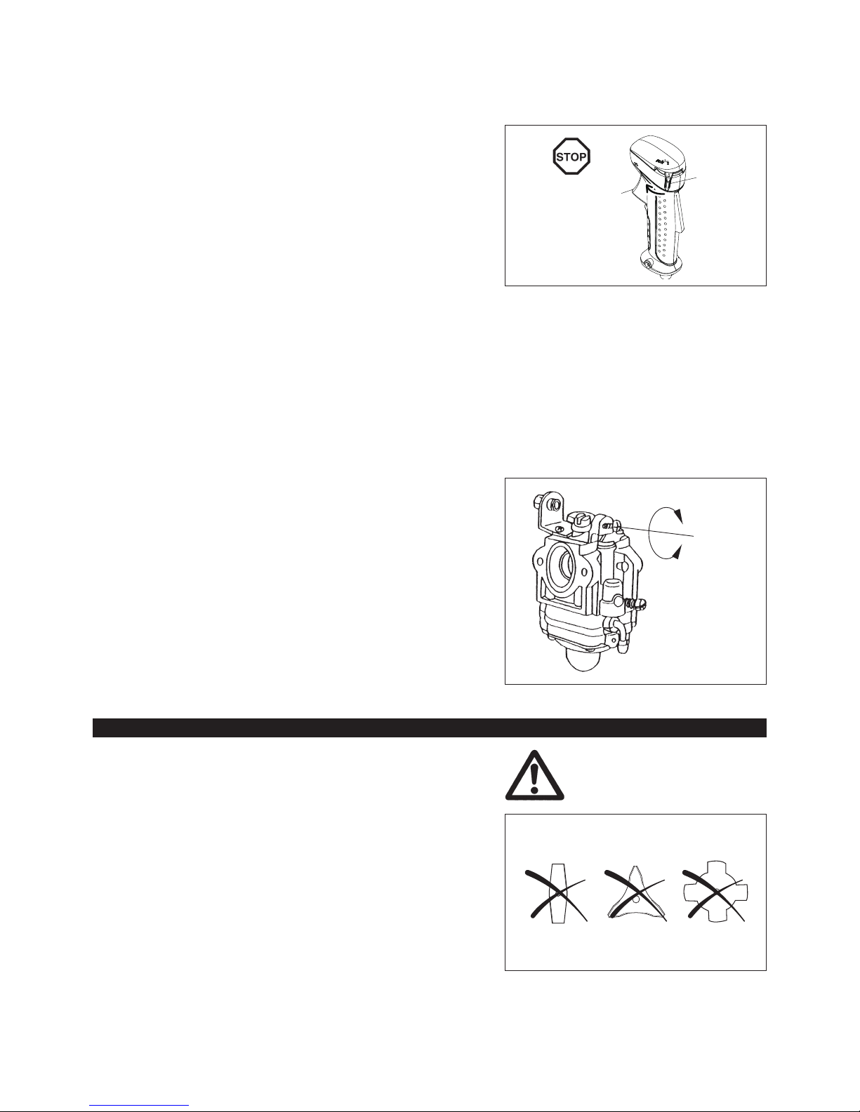
Cutting Tools
Use an applicable cutting tool for the job in hand. –
Nylon cutting heads (string trimmer heads) are suitable for trimming lawn grass.
Metal blades are suitable for cutting weeds, high grasses, bushes, shrubs,
underwood, thicket, and the like.
Never use other blades including metal multi-piece pivoting chains and flail
blades. Otherwise serious injury may result.
When using metal blades, avoid “kickback” and always prepare for an accidental –
kickback. See the section “Kickback” and “Kickback prevention.”
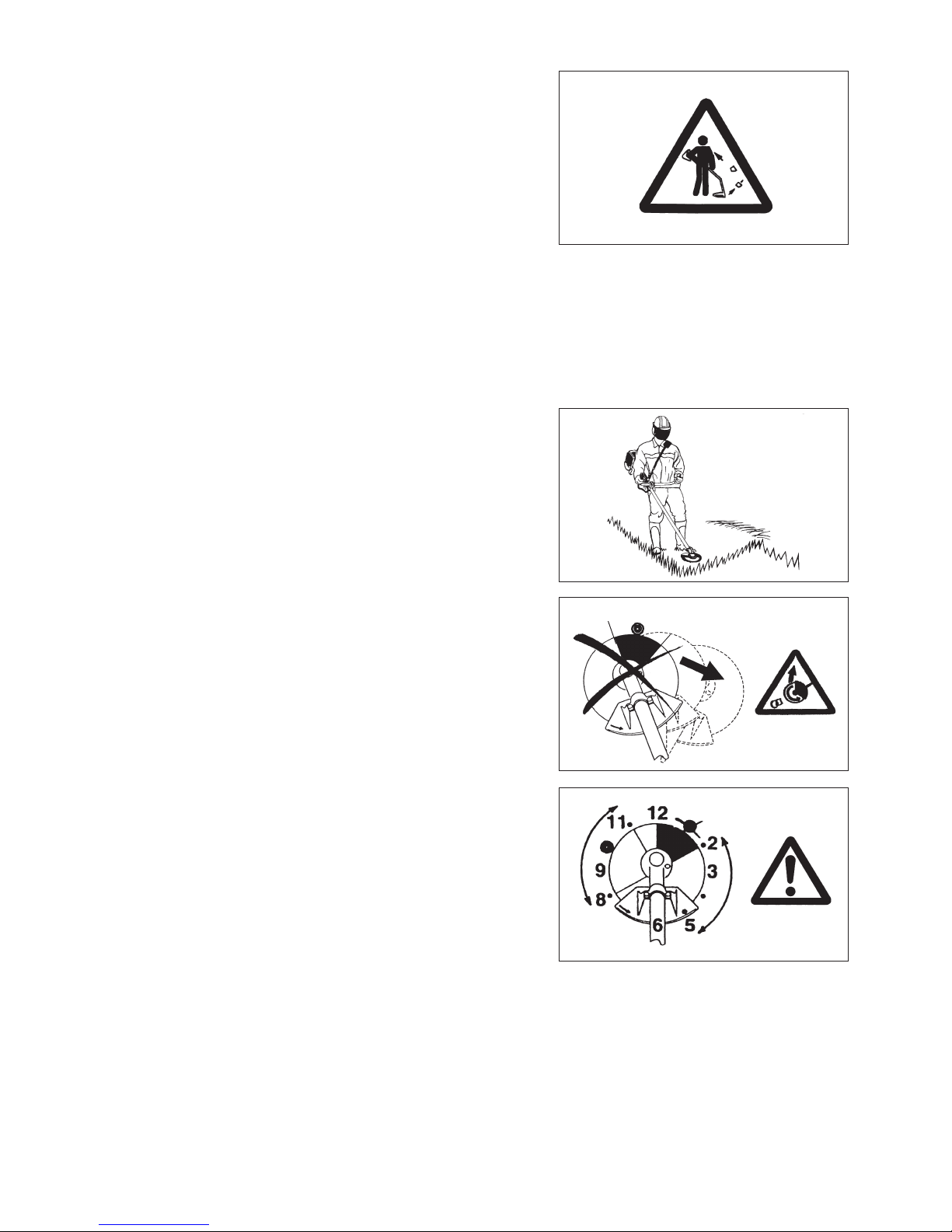
Kickback (blade thrust)
Kickback (blade thrust) is a sudden reaction to a caught or bound metal blade. –
Once it occurs, the equipment is thrown sideway or toward the operator at great
force and it may cause serious injury.
Kickback occurs particularly when applying the blade segment between 12 and 2 –
o’clock to solids, bushes and trees with 3 cm or larger diameter.
To avoid kickback: –
Apply the segment between 8 and 11 o’clock;•
Never apply the segment between 12 and 2 o’clock;•
Never apply the segment between 11 and 12 o’clock and between 2 and •
5 o’clock, unless the operator is well trained and experienced and does it at his/
her own risk;
Never use metal blades close to solids, such as fences, walls, tree trunks and •
stones;
Never use metal blades vertically, for such operations as edging and trimming •
hedges.
Vibration
People with poor circulation who are exposed to excessive vibration may –
experience injury to blood vessels or the nervous system. Vibration may cause
the following symptoms to occur in the fingers, hands or wrists: “Falling asleep”
(numbness), tingling, pain, stabbing sensation, alteration of skin color or of the
skin. If any of these symptoms occur, see a physician!
To reduce the risk of “white finger disease”, keep your hands warm during –
operation and well maintain the equipment and accessories.
Maintenance instructions
Have your equipment serviced by our authorized service center, always using –
only genuine replacement parts. Incorrect repair and poor maintenance can
shorten the life of the equipment and increase the risk of accidents.
The condition of the cutter, in particular of the cutting tool of the protective –
devices and also of the shoulder harness must be checked before commencing
work. Particular attention is to be paid to the metal blades which must be correctly
sharpened.
Turn off the engine and remove spark plug connector when replacing or –
sharpening cutting tools, and also when cleaning the cutter or cutting tool.

6
Never straighten or weld damaged cutting tools.
Pay attention to the environment. Avoid unnecessary throttle operation for –
less pollution and noise emissions. Adjust the carburetor correctly.
Clean the equipment at regular intervals and check that all screws and nuts –
are well tightened.
Never service or store the equipment in the vicinity of naked flames. –
Always store the equipment in locked rooms and with an emptied fuel tank. –
When cleaning, servicing and storing the equipment, always attach the cover –
to the metal blade.
Observe the relevant accident prevention instructions issued by the relevant trade associations and by the insurance companies.
Do not perform any modifications to the equipment as this will endanger your safety.
The performance of maintenance or repair work by the user is limited to those activities as described in the instruction manual. All other work is
to be done by an Authorized Service Agent. Use only genuine spare parts and accessories released and supplied by DOLMAR.
Use of non-approved accessories and tools means increased risk of accidents.
DOLMAR will not accept any liability for accidents or damage caused by the use of non-approved cutting tools and fixing devices of cutting tools,
or accessories.
First Aid
In case of accident make sure that a first-aid box is available in the vicinity of
the cutting operations. Immediately replace any item taken from the first aid box.
When asking for help, please give the following
information:
Place of accident –
What happened –
Number of injured persons –
Kind of injuries –
Your name –
For European countries only
EC Declaration of Conformity
The undersigned, Rainer Bergfeld, as authorized by Dolmar GmbH, declares that the DOLMAR machine(s):
Designation of Machine: Petrol Brushcutter
Model No./ Type: MS-4215
Specifications: see “TECHNICAL DATA” table
are of series production and
Conforms to the following European Directives:
2000/14/EC, 2006/42/EC
And are manufactured in accordance with the following standards or standardized documents:
EN ISO 11806-1
The technical documentation is on le at:
Dolmar GmbH,
Jenfelder Straße 38, Abteilung FZ, D-22045 Hamburg
The conformity assessment procedure required by Directive 2000/14/EC was in Accordance with annex V.
Measured Sound Power Level: 107.44 dB
Guaranteed Sound Power Level: 109 dB
23. 8. 2013
Rainer Bergfeld
Managing Director

Model MS-4215
Handle type U handle
Dimensions: length x width x height (without cutting blade) mm 1,710 x 630 x 515
Net weight (without plastic guard and cutting blade) kg 7.2
Volume (fuel tank) cm
3
1,100
Engine displacement cm
3
40.2
Maximum engine performance kW 1.47 at 7,000 min
-1
Engine speed at recommended max. spindle speed min
-1
10,000
Maximum spindle speed (corresponding) min
-1
6,800
Fuel consumption kg/h 0.98 (32.8 oz/h)
Specific fuel consumption g/kWh 1134.5 (29.9 oz/kWh)
Idling speed min
-1
2,800
Clutch engagement speed min
-1
3,600
Carburetor type Diaphragm type
Ignition system type Solid state ignition
Spark plug type NGK BPMR7A
Electrode gap mm 0.6 – 0.7
Vibration per
ISO 22867
Right handle
(Rear grip)
a
hv eq
m/s
2
4.06
Uncertainty K m/s
2
2.14
Left handle
(Front grip)
a
hv eq
m/s
2
5.85
Uncertainty K m/s
2
1.19
Sound pressure level average to
ISO 22868
L
PA eq
dBA 95.91
Uncertainty K dBA 1.79
Sound power level average to
ISO 22868
L
WA eq
dBA 107.44
Uncertainty K dBA 1.48
Mixture ratio (Fuel: DOLMAR 2-stroke oil) 25 : 1
Cutting tool (cutter blade dia.) mm 305 (with two-edged blade)
Gear ratio 13/19
• Due to our continuing program of research and development, the specifications herein are subject to change without notice.
• Specifications may differ from country to country.
TECHNICAL DATA
7
DESIGNATION OF PARTS
No. DESIGNATION OF PARTS
1 Fuel tank
2 Clutch case
3 Hanger
4 I-O switch (on/off)
5 Throttle lever
6 Throttle wire
7 Handle
8 Handle holder
9 Shaft
10 Cutting tool guard (Protector)
11 Gear case
12 Spark plug
13 Exhaust muffler
14 Exhaust pipe
15 Recoil starter
16 Starter knob
17 Primer pump
18 Choke lever
19 Air cleaner
20 Fuel tank cap
19
12
13
20
15
16
18
17
14
1
2
8
9
10
7
3
11
4
5
6
MS-4215
8

CAUTION: Before doing any work on the brushcutter, always switch off the motor
and pull the spark plug connector off the spark plug.
Always wear protective gloves.
CAUTION: Start the brushcutter only after having assembled it completely.
After checking the parts, fasten the drive shaft to the engine with four bolts –
M6 x 20 (1). At this time, fasten also the earth terminal (2) of the stop cord to the
engine.
CAUTION: Before doing any work on the brushcutter, always stop the engine and
pull the spark plug connector off the spark plug. Always wear protective
gloves!
CAUTION: Start the brushcutter only after having assembled it completely.
ASSEMBLY OF ENGINE AND SHAFT
MOUNTING OF HANDLE
(1)
(2)
(3)
(4)
(5)
For model MS-4215
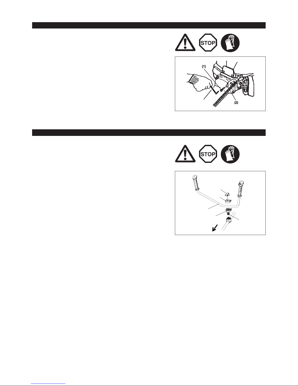
Loosen knob (1). –
Place handle (4) between handle clamp (2) and handle holder (3). –
Adjust handle (4) to an angle that provides a comfortable working position and –
then secure by firmly hand-tightening knob (1).
CAUTION: Do not forget to mount spring (5).
Engine
9
For model MS-4215
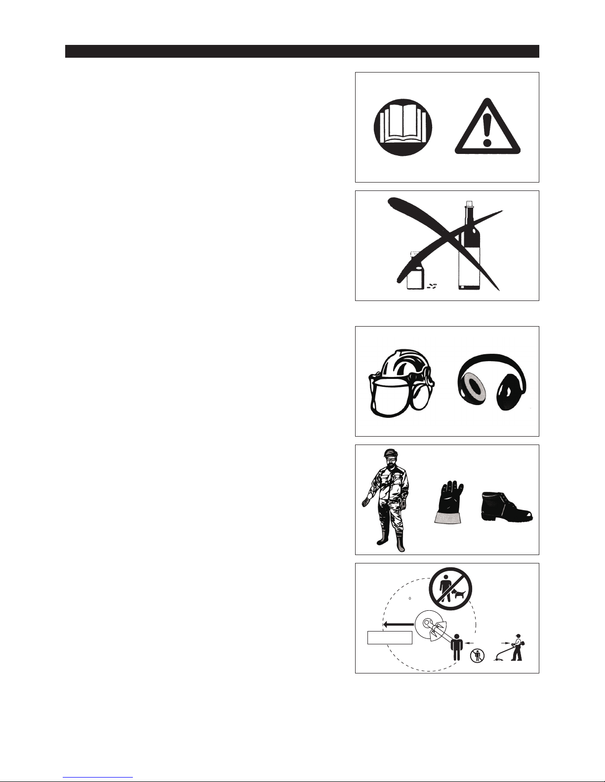
– After assembling the handle, fit the control cable to the shaft by two clips (1).
Clips (1)
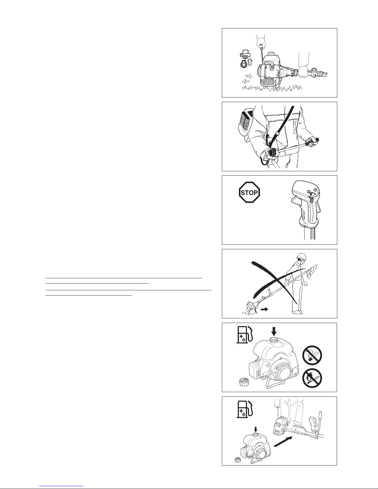
To meet the applicable safety provisions, only the tool/protector
combinations as indicated in the table must be used.
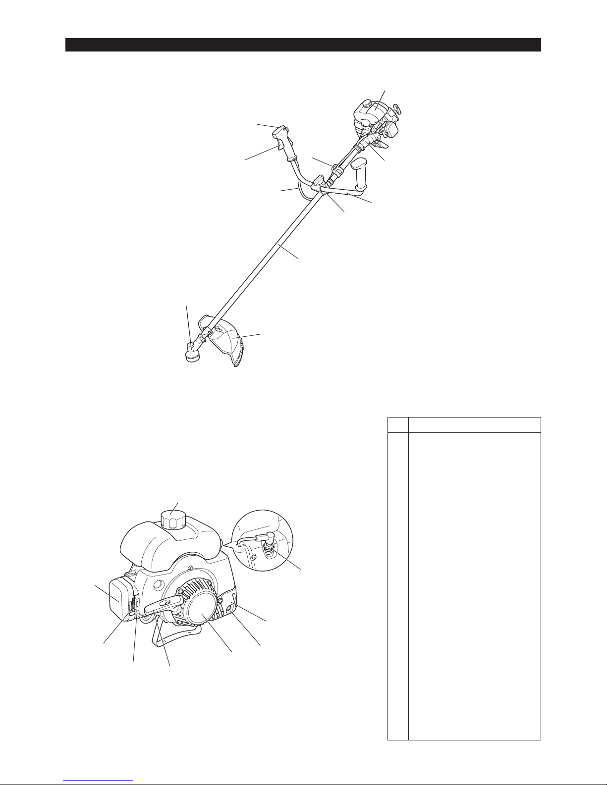
Be sure to use genuine DOLMAR cutter blades or
nylon cutting head.
The cutter blade must be well polished, free of cracks or breakage. If –
the cutter blade hits against a stone during operation, stop the engine
and check the blade immediately.
Resharpening or replace the cutter blade every three hours of –
operation.
If the nylon cutting head hits against a stone during operation, stop the –
engine and check the nylon cutting head immediately.
Metal blade Protector for metal blades
MOUNTING OF PROTECTOR
CAUTION: The appropriate protector must always be installed, for your
own safety and in order to comply with accident-prevention
regulations.
Operation of the equipment without the guard being in place
is not permitted.
The outside diameter of the cutter blade must be 255 mm
(10”). Cutter blades with outside diameter of 305 mm or
12 inches can be used only for those with two or three
blades.
10
Nylon cutting head
Protector for nylon cutting head
(1)
(2)
(3)
(3)
(4)
Hex wrench
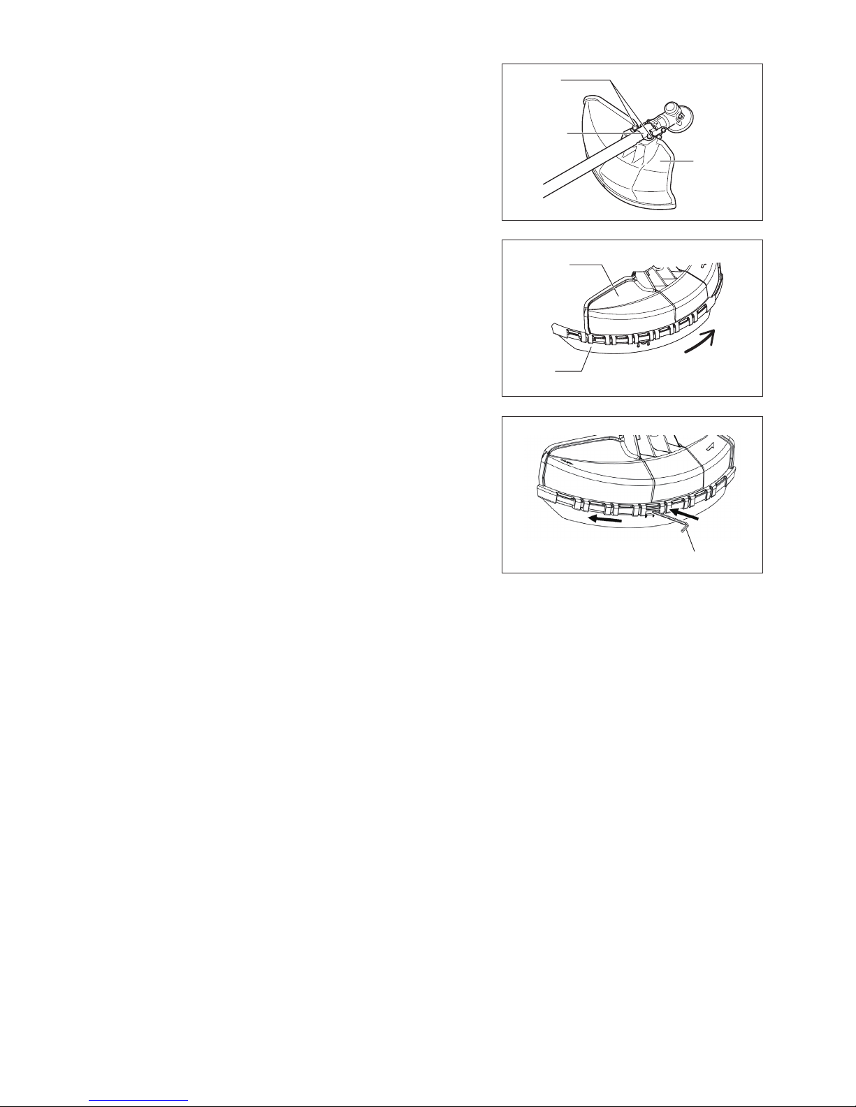
In use of the metal blade, fix the protector (3) to the clamp (2) with two bolts (1). –
NOTE: Tighten the right and left bolts evenly so that the gap between the clamp (2)
and the protector (3) will be constant.
Otherwise, the protector sometimes may not function as specified.
In cases where the nylon cord cutter is to be used, be sure to mount the nylon –
cord cutter protector (4) onto the metal blade protector (3).
Mount the nylon cord cutter protector (4) by sliding it into place from the flank of –
the metal blade protector (3) as shown.
Remove tape adhered to cutter, which cuts nylon cord, on nylon cord cutter –
protector (4).
CAUTION: Be sure to push in nylon cord cutter protector (4) until it is fully inserted.
Take care not to injure yourself on the cutter for cutting the nylon cord.
To remove the nylon cord cutter protector (4), apply a hex wrench into the notch –
on the metal blade protector (3), push it in and meanwhile slide the nylon cord
cutter protector (4).
11

(4)
(3)
(2)
(1)
(4)
Insert the hex wrench through the hole in the gear case and rotate the receiver –
washer (4) until it is locked with the hex wrench.
Loosen the nut (1) (left-hand thread) with the socket wrench and remove the nut –
(1), cup (2), and clamp washer (3).
Turn the machine upside down, and you can replace the cutter blade or nylon
cutting head easily.
Mounting of cutterblade
With the hex wrench still in place.
Mount the cutter blade onto the shaft so that the guide of the receiver washer (4) –
fits in the arbor hole in the cutter blade. Install the clamp washer (3), cup (2), and
secure the cutter blade with the nut (1).
[Tightening torque: 20 - 30 N·m]
NOTE: Always wear gloves when handling the cutter blade.
NOTE: The cutter blade-fastening nut (with spring washer) is a consumable part.
If there appears any wear or deformation on the spring washer, replace the
nut.
Hex wrench
Hex wrench
Mounting of nylon cutting head
The clamp washer (3), cup (2), and nut (1) are not necessary for mounting the –
nylon cutting head. The nylon cutting head should go on top of the receiver
washer (4).
Insert the hex wrench through the hole in the gear case and rotate the receiver –
washer (4) until it is locked with the hex wrench.
Then screw the nylon cutting head onto the shaft by turning it counterclockwise. –
Remove the hex wrench. –
MOUNTING OF CUTTER BLADE OR NYLON CUTTING HEAD
12
Rotation
Make sure that the blade is the left way up. –
Loosen Tighten
Hex wrench
Handling petroleum products
Utmost care is required when handling fuel. Fuel may contain substances similar
to solvents. Refuel either in a well ventilated area or outdoors. Do not inhale fuel
vapors, avoid any contact of fuel or oil with your skin.
Mineral oil products degrease your skin. If your skin comes in contact with these
substances repeatedly and for an extended period of time, various skin diseases
may result. In addition, allergic reactions are known to occur. Eyes can be irritated
by contact with oil, fuel etc.
If oil comes into your eyes, immediately wash them with clear water.
If your eyes are still irritated, see a doctor immediately.
Fuel and oil mixture
The engine of the brushcutter is a high-efficiency two-stroke engine.
It is run with a mixture of fuel and two-stroke engine oil. The engine is designed
to use unleaded regular fuel with a min. Octane value of 91 RON. If no such fuel
is available, you can use fuel with a higher octane value. This will not affect the
engine, but may cause poor operating behavior.
A similar situation will arise from the use of leaded fuel. To obtain optimum engine
performance and to protect your health and the environment, only unleaded fuel
should be used!
For engine lubrication use a two-stroke engine oil (quality grade: TC-3), which is
added to the fuel. The engine has been designed to use DOLMAR two-stroke engine
oil at mixture ratio of 25:1 to protect the environment. In addition, a long service life
and reliable operation with a minimum emission of exhaust gasses is assured. It is
absolutely essential to observe a mixture ratio of 25:1 DOLMAR 2-stroke engine oil.
Otherwise reliable function of the brushcutter cannot be guaranteed.
The correct mixture ratio:
Mix 25 parts gasoline with 1 part DOLMAR 2-stroke engine oil (see table on right).
NOTE: For preparing the fuel-oil mixture first mix the entire oil quantity with
half of the fuel required in an approved can which meets or exceeds
all local code standards, then add the remaining fuel. Throughly shake
the mixture before filling it into the brushcutter tank. It is not wise to
add more engine oil than specified to ensure safe operation. This will
only result in a higher production of combustion residues which will
pollute the environment and clog the exhaust channel in the cylinder,
the spark plugs as well as the muffler. In addition, fuel consumption
will rise and the performance will be decreased.
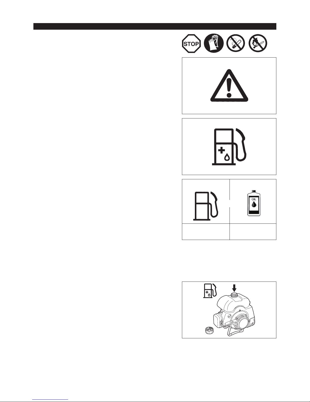
Refuelling
Never perform refuelling operations in a closed, unventilated area.
The engine must be switched off!
Thoroughly clean the area around the gas cap, to prevent dirt from getting into –
the fuel tank.
Unscrew the gas cap and fill the tank with fuel. –
Never fill the fuel tank to the very top. –
Securely screw on the gas cap. –
Wipe the screw plug and tank with an absorbent after refuelling! –
Allow cloths to dry and discard in a proper container.
Storage of Fuel
Fuel cannot be stored for an unlimited period of time.
Purchase only the quantity required for a 4 week operating period. Only use
approved fuel storage containers.
Observe the Safety Instructions on page 4!
25:1
+
Gasoline
(premium unleaded)
1,000 cc (1L)
5,000 cc (5L)
10,000 cc (10L)
40 cc
200 cc
400 cc
FUELS/REFUELLING
13
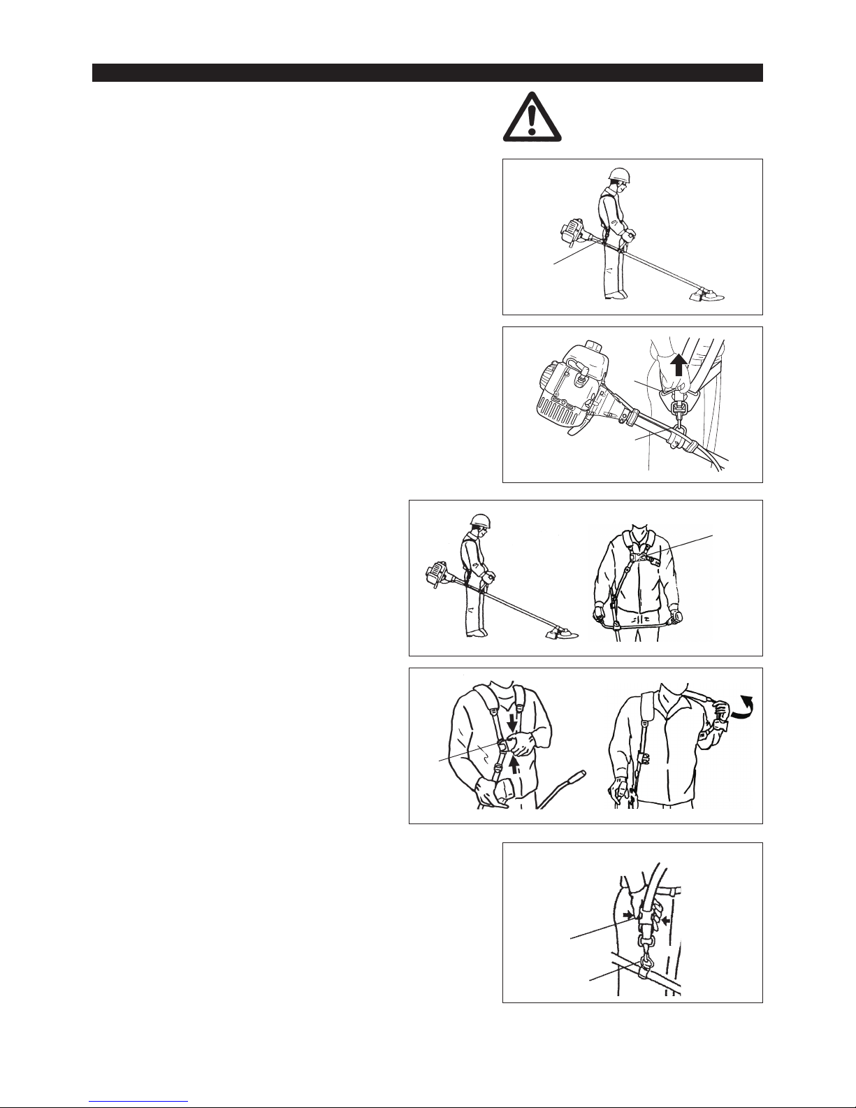
Detachment
In case of emergency, remove the emergency detachment lever (1) by pulling –
strongly with a finger. The machine sill detach from body.
Be extremely careful to maintain control of the machine at this time. Do not allow
the machine to be deflected toward you or anyone in the work vicinity.
WARNING: Failure to maintain complete control of the machine at all could result in
serious bodily injury or DEATH.
Either type I or II below is included in the tool package. Always wear the shoulder
harness when operating the brushcutter.
Type I
Attachment of shoulder harness
Adjust the strap length so that the cutter blade will be kept parallel with the –
ground.
Type II
Attachment of shoulder harness
Adjust the strap length so that the cutter blade will be kept –
parallel with the ground.
NOTE: Be careful not to trap clothing, etc., in the buckle.
Detachment
In case of emergency, push the notches (2) at both sides, –
and you can detach the machine from you.
Be extremely careful to maintain control of the machine at this
time. Do not allow the machine to be deflected toward you or
anyone in the work vicinity.
WARNING: Failure to maintain complete control of the machine
at all could result in serious bodily injury or DEATH.
Hanger
(1)
Hanger
Buckle
(2)
CORRECT HANDLING OF MACHINE
14
Type III
Attachment of shoulder harness
Adjust the strap length so that the cutter blade will be kept parallel with the –
ground.
Detachment
In an emergency, push the notches (1) at both sides, and you can detach the –
machine from you.
Be extremely careful to maintain control of the machine at this time. Do not allow
the machine to be deflected toward you or anyone in the work vicinity.
WARNING: Failure to maintain complete control of the machine at all could result in
serious bodily injury or DEATH.
Hanger
(1)

(3)
(1)
(2)
(4)
(5)
Starting
Move at least 3m (10ft) away from the place of refuelling. Place the brushcutter on a clean piece of ground taking care that the cutting tool does
not come into contact with the ground or any other objects.
First place the machine on the ground. –
Give a gentle push on the primer pump (4) repeatedly (7-10 times) until fuel –
comes into the primer pump.
Move the choke lever (5) to the top position ( –
).
Firmly hold the unit by your left hand, as illustrated. –
Slowly pull the starter grip until resistance is felt and continue with a smart pull. –
Do not pull out the starter rope to its full extent and do not allow the starter handle –
to be retracted without control, but ensure that it is retracted slowly.
Repeat the starting operation until initial ignitions are heard. –
Depress the choke lever ( –
) and pull the starter rope again until the engine
starts.
As soon as the engine starts, immediately tap and release the throttle, thus –
releasing the half-throttle lock so that the engine can run in idle.
Run the engine for approximately one minute at a moderate speed before –
applying full throttle.
Caution during operation:
If the throttle lever is opened fully in a no-load operation, the engine rotation is increased to 10,000 min
-1
or more. Never operate the engine at a
higher speed than required and at an approximate speed of 6,000 - 8,000 min-1.
Cold start
Grasp the handle (hand pressure activates the safety lock-off lever (1)). –
Press the throttle lever (2) and hold it down. –
Push the I-O switch (3) to START. –
PUTTING INTO OPERATION
Observe the applicable accident prevention regulations!
15
IDLE ADJUSTMENT
Never attempt to make engine adjustments while the unit is running and strapped –
to the operator. Always make engine adjustments with the unit resting on a flat,
clear surface.
The cutter blade or the nylon cutting head should not run when the control lever is
fully released. If necessary, adjust the idle rpm using the idle adjusting screw.
Checking the Idle speed
Idle speed should be set to 2,600 min –
-1
.
If necessary correct it by means of the idle adjustment screw (the blade or the
nylon cutting head must not turn when the engine is on idle.)
Turning in the screw clockwise will cause an increase in the engine speed,
whereas turning the screw counterclockwise will reduce the engine speed.
CAUTION:
The cutting tools mentioned below must only be resharpened by an authorized
facility. Manual resharpening will result in imbalances of the cutting tool causing
vibrations and damage to the equipment.
cutter blade –
An expert resharpening and balancing service is provided by Authorized Service
Agents.
NOTE:
To increase the service life of the cutter blade it may be turned over once, until both
cutting edges have become blunt.
RESHARPENING THE CUTTING TOOL
Stopping
1) Release the throttle lever (2) fully, and when the engine rpm has lowered, set the
I-O switch (1) to STOP the engine will now stop.
2) Be aware that the cutting head may not stop immediately and allow it to slow
down fully.
OPERATION OF THROTTLE LEVER
With the throttle lever main unit held by hand (with the lock-off lever pushed), pull
the throttle lever to increase the engine rotation.
Release the throttle lever to let the engine run idle.
Release the hand from the throttle lever main unit. The lock-off lever returns
automatically so that the throttle lever is not pulled by mistake.
(2)
(1)
(1)
(2)
Starting the warm engine
As described above, except without moving the choke lever (choke lever remains in the down position). –
increase
Idle adjusting
screw
reduce
16
NYLON CUTTING HEAD
The nylon cutting head is a dual line trimmer head that has bump & feed mechanism
or auto feed mechanism (ultra auto) (country specific).
The nylon cutting head with bump & feed mechanism feeds out the nylon cord after
tapping the trimmer head on the ground. The nylon cutting head with auto feed
mechanism automatically feeds out the nylon cord by the changes in centrifugal
force.
Operation
The most effective cutting area is shown by the shaded area. –
To feed the nylon cord, increase the nylon cutting head speed to approx. –
6,000 min
-1
and tap the nylon cutting head lightly on the ground. With auto feed
mechanism, trigger action can feed the nylon cord.
If the nylon cutting head does not feed out by tapping, rewind/replace the nylon –
cord by following the procedures described under “Replacing the nylon cord.”
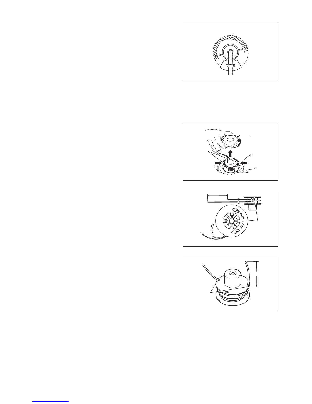
Replacing the nylon cord (BUMP & FEED)
WARNING: Make sure that the cover of the nylon cutting head is secured to the
housing properly as described below. Failure to properly secure the
cover may cause the nylon cutting head to fly apart resulting in serious
personal injury.
Press inward on the housing latches and lift upward to remove the cover.
Discard any of the remaining nylon cord.
Hook the middle of the new nylon cord to the notch located at the center of the spool
between the 2 channels provided for the nylon cord. One side of the cord should be
about 80 mm longer than the other side.
Wind both ends firmly around the spool in the direction marked on the head for left
hand direction indicated by LH.
Wind all but about 100 mm of the cords, leaving the ends temporarily hooked
through a notch on the side of the spool.
Most effective cutting area
Cover
PressPress
Latches
80 mm
Spool
For left hand
rotation
Notches
100 mm
17
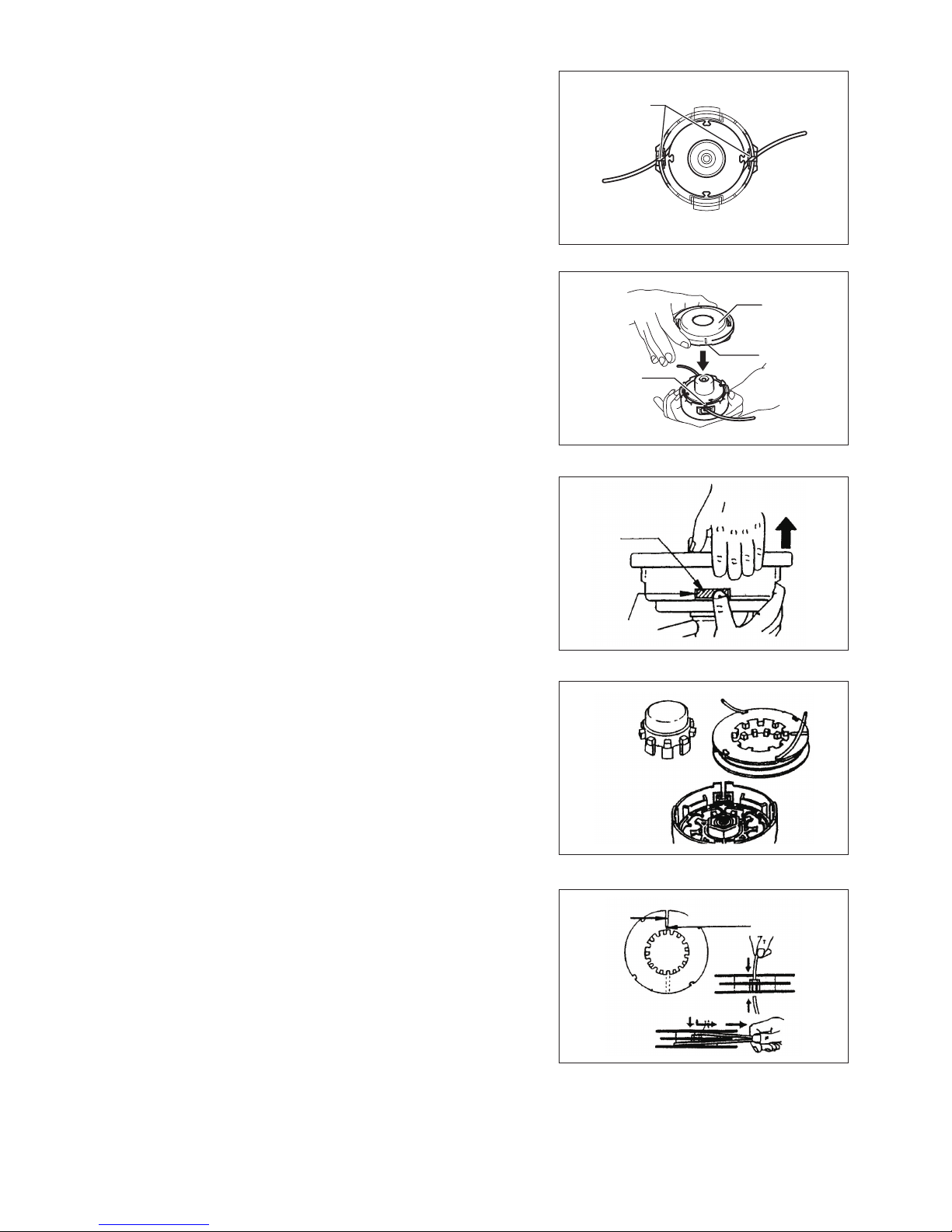
Mount the spool in the housing so that the grooves and protrusions on the spool
match up with those in the housing. Keep the side with letters on the spool visible
on the top. Now, unhook the ends of the cord from their temporary position and feed
the cords through the eyelets to come out of the housing.
Align the protrusion on the underside of the cover with the slots of the eyelets.
Then push cover firmly onto the housing to secure it. Make sure the latches fully
spread in the cover.
Replacing the nylon cord (ULTRA AUTO)
1. Put off cover from housing, pressing two cover locking tabs located oppositely
on side of the housing.
2. Take off tab knob and spool from the housing.
3. Put each one end of two cutting lines into each holes at innermost of the slot on
one of spool outer anges. Put the lines into spool gutters through each slit on
the anges.
Eyelets
Cover
Protrusion
Slot of
eyelet
Pull up
Cover
locking tab
Tab knob
Spool
Slit
There is a hole
innermost of the slit
18
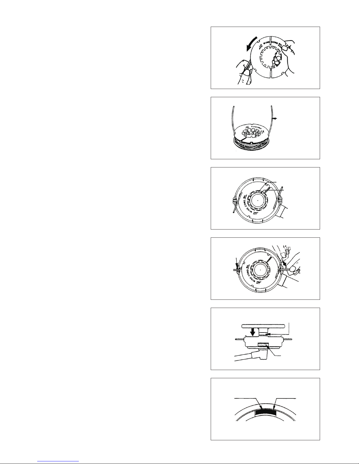
4. Wind the lines up rmly to the direction slown by left-hand (LH) arrow on the
ange. Do not cross the lines.
5. Wind all but about 100 mm (3-15/16”) of the cords, leaving the end temporarily
hooked through a notch on the side of the spool.
6. Put tab knob onto the housing hub, positioning it can freely move up and down
against spring tension. Put the spool into the housing, aligning the teeth on
spool and tap knob alternately like gears.
7. Put in the cutting lines through the slot of eyelets.
8. Put the cover onto the housing, aligning the tabs on cover and the windows
on housing. Make sure the cover is secured exactly to the housing. Outer
edge of cover locking tab and outer surface of the housing should be on same
circumference.
To “LH” direction
100 mm from
notches
Tab knob’s teeth
Spool’s teeth
Cover locking tab
Housing window
Outer edge
of cover
locking tab
Outer
surface of
housing
19
Wind tightly
(3)
(4)
1. Before operation, pay particular attention to the tightness of Cutter Blade or
nylon cutting head.
Check bolts and nuts and retighten if necessary.: Every 8 hour (Daily)
2. Check clogging of the cooling air passage and the cylinder ns. Clean them if
necessary.: Every 8 hours (Daily)
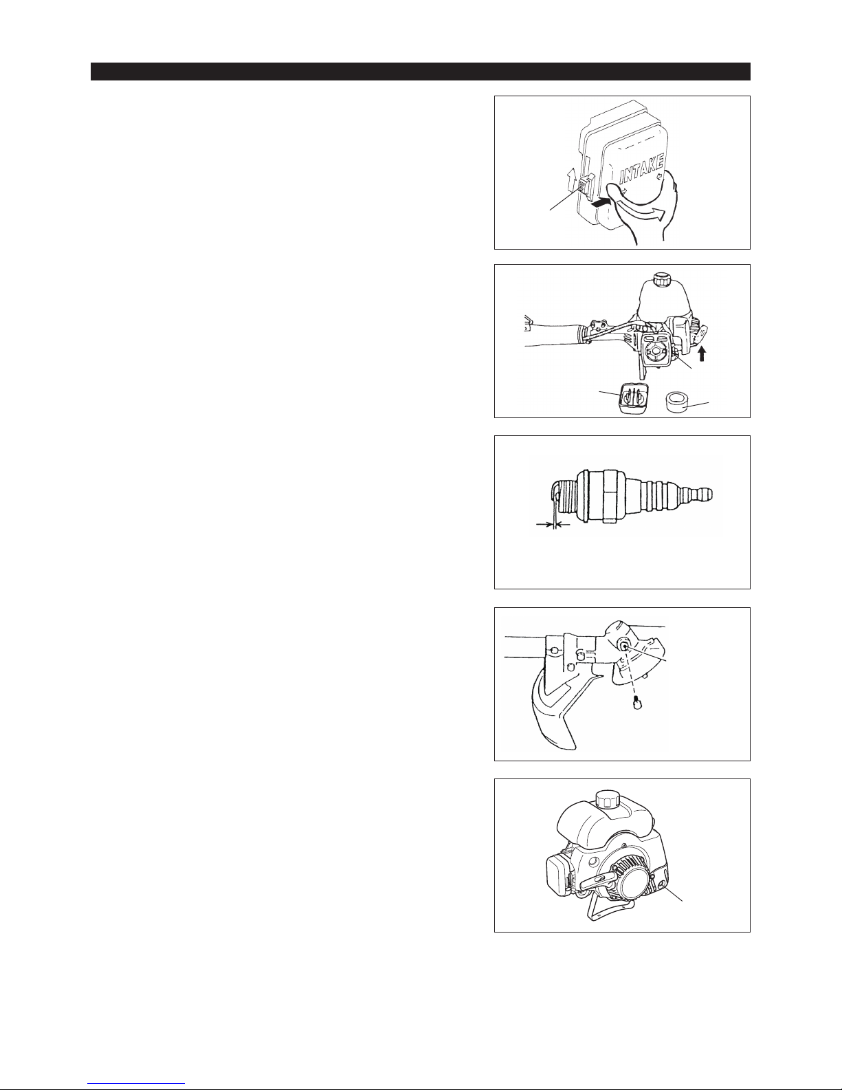
3. Cleaning of air cleaner
Raise the lock lever (1) of the air cleaner cover and release the lock. –
Hold the right and left sides of the air cleaner cover, press it to the inside and –
then remove it.
Push the choke lever (2) up (arrow), to prevent dirt particles from entering the –
carburetor.
Remove the sponge element (3). –
Wash it with lukewarm water and then dry it throughly.
After cleaning, put back the sponge element and install the air cleaner cover (4) –
and tighten the screw to secure.
NOTE: If there is excessive dust or dirt adhering to the air cleaner, clean it every
day. A clogged air cleaner may make it difficult or impossible to start or run
the engine at proper rotational speeds.
5. Supply of grease to gear case.
Apply grease (SHELL ALVANIA No. 3 or equivalent) to the gear case through
the grease hole (3) every 30 hours.
(Genuine DOLMAR grease may be purchased from your DOLMAR dealer.)
6. Cleaning of mufer exhaust port: Every 50 hours (Monthly)
If the exhaust port (4) is clogged with carbon, remove it by scraping and tapping
gently with a screwdriver or the like.
7. Check of fuel lter. If clogged, clean the lter.
8. Replace fuel lines.: Every 200 hours (Yearly)
9. Overhaul engine.: Every 200 hours (Yearly)
10. Replace packings and gaskets with new ones.: Every time engine is
reassembled.
0.6 mm – 0.7 mm
(0.024” – 0.028”)
Gear case
MAINTENANCE SCHEDULE
(1)
(2)
(3)
(4)
4. Checkup of spark plug.: Every 8 hours (Daily)
The gap between the two electrodes of the spark plug should be 0.6 to 0.7 mm
(0.024” to 0.028”).
If the gap is too wide or too narrow, adjust it.
If the spark plug is clogged with carbon or fouled, clean it thoroughly or replace
it.
20

When the machine is in storage for a long time, drain fuel from the fuel tank and –
carburetor, as follows: Drain all fuel from the fuel tank. Dispose of properly and in
accordance with all local laws.
Remove the spark plug and a few drops of oil into the spark plug hole. Then, pull –
the starter gently, so that oil covers the engine inside and tighten the spark plug.
Clear dirt or dust from the cutter blade and outside of engine, wipe them with a –
oil-immersed cloth and keep the machine in a place as dry as possible.
Drain fuel
Humidity
Fault location
Fault System Observation Cause
Engine not starting
or with difficulty
Ignition system Ignition spark O.K. Fault in fuel supply or compression system, mechanical defect
No ignition spark I-O switch operated, wiring fault or short circuit, spark plug or
connector defective, ignition module faulty
Fuel supply Fuel tank filled Incorrect choke position, carburetor defective, fuel supply line bent
or blocked, fuel dirty
Compression No compression
when pulled over
Cylinder bottom gasket defective, crankshaft seals damaged,
cylinder or piston rings defective or improper sealing of spark plug
Mechanical fault Starter not engaging Broken starter spring, broken parts inside of the engine
Warm start problems Tank filled ignition
spark existing
Carburetor contaminated, must be cleaned
Engine starts but
dies immediately
Fuel supply Tank filled Incorrect idling adjustment, carburetor contaminated
Fuel tank vent defective, fuel supply line interrupted, cable or I-O
switch faulty
Insufficient
performance
Several systems
may simultaneously
be affected
Engine idling poor Air filter contaminated, carburetor contaminated, muffler clogged,
exhaust duct in the cylinder clogged
STORAGE
General Engine assembly, screws and nuts Visual inspection for damage and tightness
Check for general condition and security
After each refuelling Throttle lever
Safety lock key
ON-OFF switch
Functional check
Functional check
Functional check
Daily Sponge element (air filter)
Cooling air duct
Cutting blade
Idling speed
To be cleaned
To be cleaned
Check for damage and sharpness
Inspection (cutting tool must not move)
Weekly Spark plug
Muffler
Inspection, replace if necessary
Check and if necessary clean the opening
Quarterly Suction head (gas line filter)
Fuel tank
To be replaced
To be cleaned
Shutting down procedure Fuel tank
Carburetor
Empty fuel tank
Operate until engine runs out of fuel
21

TROUBLESHOOTING
Before making a request for repairs, check a trouble for yourself. If any abnormality is found, control your machine according to the description
of this manual. Never tamper or dismount any part contrary to the description. For repairs, contact Authorized Service Agent or local dealership.
When the engine does not start after warm-up operation:
If there is no abnormality found for the check items, open the throttle by about 1/3 and start the engine.
State of abnormality Probable cause (malfunction) Remedy
Engine does not start
I-O switch is set to STOP Set the I-O switch to OPERATION.
Failure to operate primer pump Push 7 to 10 times.
Low pulling speed of starter rope Pull strongly
Lack of fuel Feed fuel
Clogged fuel lter Clean
Bent fuel tube Straighten fuel tube
Deteriorated fuel Deteriorated fuel makes starting more difcult.
Replace with new one. (Recommended
replacement: 1 month)
Excessive suction of fuel Set throttle lever from medium speed to high
speed, and pull starter handle until engine
starts. Once engine starts, cutter blade
starts rotating. Pay full attention to cutter
blade.
If engine will not start still, remove spark plug,
make electrode dry, and reassemble them as
they originally are. Then, start as specied.
Detached plug cap Attach securely
Contaminated spark plug Clean
Abnormal clearance of spark plug Adjust clearance
Other abnormality of spark plug Replace
Abnormal carburetor Make request for inspection and maintenance.
Starter rope cannot be pulled Make request for inspection and maintenance.
Abnormal drive system Make request for inspection and maintenance.
Engine stops soon
Engine speed does not increase
Insufcient warm-up Perform warm-up operation
Choke lever is set to “CLOSE” although
engine is warmed up.
Set to “OPEN”
Clogged fuel lter Clean
Contaminated or clogged air cleaner Clean
Abnormal carburetor Make request for inspection and maintenance.
Abnormal drive system Make request for inspection and maintenance.
Cutter blade does not rotate Loosened cutter blade-tightening nut Tighten securely
Twigs caught by cutter blade or dispersionpreventing cover.
Remove foreign matter
Abnormal drive system Make request for inspection and maintenance.
Main unit vibrates abnormally Broken, bent or worn cutter blade Replace cutter blade
Loosened cutter blade-tightening nut Tighten securely
Shifted convex part of cutter blade and cutter
blade support tting.
Attach securely
Abnormal drive system Make request for inspection and maintenance.
Cutter blade does not stop immediately High idling rotation Adjust
Detached throttle wire Attach securely
Abnormal drive system Make request for inspection and maintenance.
Engine does not stop Detached connector Attach securely
Abnormal electric system Make request for inspection and maintenance.
Stop engine immediately
Stop engine immediately
Stop engine immediately
Run engine at idling, and set choke lever
to CLOSE
22

Merci beaucoup d’avoir choisi la débroussailleuse de DOLMAR. Nous sommes
ravis de pouvoir vous proposer la débroussailleuse de DOLMAR, résultat d’un
long programme de développement et de nombreuses années d’expérience et de
connaissances.
Veuillez lire, comprendre et suivre ce livret qui explique en détails les nombreuses
caractéristiques qui en font un outil d’une performance exceptionnelle. Il vous aidera
à obtenir les meilleurs résultats possibles de votre débroussailleuse DOLMAR.
Table des matières Page
Symboles .....................................................................23
Consignes de sécurité .................................................24
Caractéristiques techniques ........................................28
Nomenclature des pièces ............................................29
Montage du moteur et de l’arbre .................................30
Montage de la poignée ................................................30
Montage du dispositif de protection .............................31
Montage de la lame de coupe ou de la tête à ls de
nylon ............................................................................33
Carburant/ravitaillement ..............................................34
Maniement correct de l’appareil ..................................35
Mise en marche ...........................................................36
Réaffûtage de l’outil de coupe .....................................37
Programme d’entretien ................................................41
Entreposage ................................................................42
Le manuel d’instructions comporte les symboles suivants.
Lisez le manuel d’instructions et
respectez les avertissements et
précautions de sécurité !
Éloigner les personnes et les animaux
de la zone de travail
User d’attention et de soins particuliers
Porter un casque protecteur, des
lunettes de protection et des protègeoreilles
Interdit Vitesse d’outil maximale autorisée
Rester à distance Mélange d’huile et de carburant
Danger d’objets volants Démarrage manuel du moteur
Ne pas fumer Arrêt d’urgence
Pas de flamme nue Premiers soins
Porter des gants de protection SOUS TENSION/DÉMARRAGE
Porter des bottes de sécurité équipées
de semelles antidérapantes. Il est
conseillé d’utiliser des bottes de sécurité
à doigts de pieds métalliques.
HORS TENSION/ARRÊT
Choc en retour
SYMBOLES
Français
(Instructions d’origine)
23

(1)
(3)
(2)
(4)
(5)
(6)
15m(50FT)
360
Instructions générales
Lisez ce manuel d’instructions pour vous familiariser avec l’utilisation de –
l’appareil. Sans ces informations, vous risquez de vous mettre en danger ou
de blesser d’autres personnes à cause d’une utilisation incorrecte.
Il est préférable de ne prêter l’appareil qu’à des personnes expérimentées. –
Prêtez-leur systématiquement le manuel d’instructions.
Veuillez d’abord solliciter des instructions de base auprès du vendeur, afin de –
vous familiariser avec le fonctionnement de la débroussailleuse.
Les enfants et les adolescents de moins de 18 ans ne doivent pas utiliser –
cet appareil. Les personnes de plus de 16 ans peuvent l’utiliser à des fins de
formation, mais sous la supervision d’un formateur agréé.
Faites preuve d’une extrême vigilance et attention. –
Utilisez l’appareil uniquement si vous êtes en bonne condition physique. –
Effectuez tout le travail avec calme et prudence. Vous êtes responsable par
rapport aux autres personnes.
N’utilisez jamais cet appareil après avoir consommé de l’alcool ou de la –
drogue, ou bien si vous vous sentez fatigué ou malade.
Les lois en vigueur peuvent restreindre l’utilisation de l’outil. –
Utilisation prévue de l’outil
Cet appareil est destiné uniquement à couper le gazon, les mauvaises –
herbes, les buissons et les sous-bois. Il ne doit pas être utilisé à d’autres fins,
telles que la taille des bordures ou des haies, car cela comporte un risque de
blessure.
Équipement de protection individuelle
Les vêtements que vous portez doivent être fonctionnels et adaptés, –
c’est-à-dire qu’ils doivent être près du corps, sans pour autant gêner vos
mouvements. Ne portez pas de bijoux ou de vêtements qui pourraient
s’emmêler dans les taillis ou les petits arbustes.
L’équipement de protection suivant ainsi que les vêtements de protection –
doivent être utilisés afin d’éviter des blessures au pied, à la main, aux yeux et
à la tête ainsi que pour protéger votre ouïe durant l’utilisation.
Portez toujours un casque en cas de risque de chute d’objets. Le casque de –
protection (1) doit être vérifié à intervalles réguliers pour parer à d’éventuels
dommages et il doit être remplacé au plus tard tous les 5 ans. N’utilisez que
des casques de protection agréés.
La visière (2) du casque (ou alternativement les lunettes) protège le visage –
des débris et des pierres qui volent. Pendant l’utilisation, portez toujours des
lunettes de protection ou une visière pour éviter toute blessure aux yeux.
Portez un équipement de protection antibruit adéquat afin d’éviter toute perte –
auditive (coquilles antibruit (3), bouchons d’oreille etc.).
Les vêtements de travail (4) protègent contre les débris et les pierres qui –
volent.
Nous vous recommandons fortement de porter des vêtements de travail.
Les gants (5) font partie de l’équipement prescrit et doivent toujours être –
portés pendant l’utilisation.
Lorsque vous utilisez l’appareil, portez toujours des chaussures robustes (6) –
équipées de semelles anti-dérapantes. Elles vous protégeront des blessures
éventuelles et vous assureront une bonne stabilité.
Démarrage de la débroussailleuse
Éloignez les personnes et les enfants à une distance minimum de 15 mètres –
du lieu de travail et faites attention aux animaux qui pourraient se trouver à
proximité.
Avant l’utilisation, vérifiez toujours que l’appareil ne présente aucun danger : –
Vérifiez la sécurité de l’outil de coupe, la maniabilité du levier d’accélération
ainsi que le bon fonctionnement du verrouillage du levier d’accélération.
La rotation du dispositif de coupe au repos est interdite. En cas de doute, –
vérifiez le réglage avec votre revendeur. Vérifiez que les poignées sont
propres et sèches et que l’interrupteur marche/arrêt fonctionne correctement.
CONSIGNES DE SÉCURITÉ
24
Figure schématique
15 mètres
Pause•
Transport•
Ravitaillement en carburant•
Entretien•
Remplacement d’outil•
3 mètres (10 pi)
Ne démarrez la débroussailleuse qu’en conformité avec les instructions.
Ne démarrez pas le moteur selon une autre méthode ! –
Utilisez la débroussailleuse et les outils uniquement pour les applications –
spécifiées.
Ne démarrez le moteur qu’après avoir procédé au montage complet de –
l’appareil. Le fonctionnement de l’outil n’est autorisé qu’une fois l’ensemble
des accessoires fixés !
Avant de démarrer, assurez-vous que l’outil de coupe n’est pas en contact –
avec des objets durs tels que des branches, des pierres, etc. et qu’il tournera
au démarrage.
En cas de problème avec le moteur, éteignez-le immédiatement. –
Si l’outil de coupe heurte des pierres ou d’autres objets durs, arrêtez –
immédiatement le moteur et examinez l’outil de coupe.
Examinez l’outil de coupe à intervalles réguliers courts pour vous assurer qu’il –
n’a pas subi de dommages (détection de fissures capillaires à l’aide du test
de tapping).
En cas de chute ou d’impact de l’appareil, vérifiez qu’il est en bon état avant –
de poursuivre le travail. Vérifiez qu’il n’y a pas de fuite de carburant dans
le circuit d’alimentation, et que les commandes et dispositifs de sécurité
fonctionnent correctement. En cas de dommage ou de doute, demandez à un
centre d’entretien agréé d’examiner et de réparer l’outil.
N’utilisez l’appareil qu’avec la bandoulière que vous devez régler –
correctement avant de mettre la débroussailleuse en marche. Il est très
important de régler la bandoulière selon votre taille afin d’éviter toute fatigue
supplémentaire pendant l’utilisation. Ne tenez jamais l’outil d’une seule main
pendant l’utilisation.
Tenez toujours la débroussailleuse à deux mains. –
Assurez-vous toujours d’avoir une bonne stabilité.
Utilisez l’appareil de façon à éviter d’inhaler les gaz d’échappement. Ne faites –
jamais tourner le moteur dans une pièce confinée (risque d’intoxication aux
gaz). Le monoxyde de carbone est un gaz inodore.
Éteignez le moteur lorsque vous faites une pause ou laissez l’appareil sans –
surveillance, et placez-le dans un endroit sûr pour éviter de mettre en danger
les autres personnes ou d’endommager l’outil.
Ne placez jamais la débroussailleuse sur de l’herbe sèche ou des matériaux –
combustibles.
Installez toujours le protège-lame de l’outil de coupe approuvé sur l’appareil –
avant de démarrer le moteur.
Sinon, un contact avec l’outil de coupe pourrait causer de graves blessures.
Vous devez utiliser toutes les installations protectives et protections fournies –
avec l’outil durant l’utilisation.
Ne faites jamais fonctionner le moteur si le pot d’échappement est endommagé. –
Éteignez le moteur durant le transport. –
Lorsque vous transportez l’appareil, fixez toujours le couvercle sur la lame –
métallique.
Pour éviter toute fuite de carburant, assurez-vous que l’appareil est bien fixé –
lors des transports en voiture.
Lors du transport, assurez-vous que le réservoir de carburant est –
complètement vide.
Lorsque vous déchargez l’appareil du coffre, ne laissez jamais tomber le –
moteur au sol, car cela risquerait d’endommager le réservoir de carburant.
Sauf en cas d’urgence, ne laissez jamais tomber l’appareil et ne le jetez pas –
sur le sol, au risque de l’endommager grièvement.
Veillez à soulever l’ensemble du matériel du sol lorsque vous le déplacez. Il –
est très dangereux de traîner le réservoir de carburant : cela risque de créer
des fuites de carburant, voire un incendie.
Ravitaillement en carburant
Lors du ravitaillement en carburant, coupez le moteur, éloignez-le des –
flammes nues et ne fumez pas.
Évitez tout contact entre la peau et l’essence. N’inhalez pas les vapeurs de –
carburant. Portez toujours des gants de protection durant le ravitaillement en
carburant. Changez et nettoyez régulièrement les vêtements de protection.
Veillez à ne pas renverser de carburant ou d’huile, afin d’éviter toute –
contamination du sol (protection environnementale). Nettoyez immédiatement
la débroussailleuse en cas d’écoulement de carburant.
Évitez tout contact entre vos vêtements et le carburant. Si vous renversez du –
carburant sur vos vêtements, changez-en immédiatement (pour éviter que
vos vêtements ne prennent feu).
Vérifiez régulièrement le bouchon du réservoir pour vous assurer qu’il est –
bien fermé et ne fuit pas.
Serrez soigneusement le bouchon du réservoir de carburant. Déplacez-vous –
pour démarrer le moteur (éloignez-vous à au moins 3 mètres de l’endroit où
vous avez fait le plein).
Ne faites jamais le plein dans une pièce confinée. Les vapeurs de carburant –
s’accumulent au niveau du sol (risque d’explosion).
Transportez et stockez le carburant uniquement dans des récipients agréés. –
Assurez-vous que les enfants ne peuvent pas accéder au carburant.
25
12
2
Attention :
Choc en retour
Figure
schématique
Figure
schématique
Mode d’emploi
N’utilisez l’appareil que si les conditions d’éclairage et de luminosité sont –
satisfaisantes. En hiver, soyez attentif aux zones glissantes ou mouillées, au
verglas et à la neige (risque de glissade). Assurez-vous toujours d’avoir une
bonne stabilité.
Ne coupez jamais à une hauteur supérieure aux épaules. –
Ne montez jamais sur une échelle. –
Ne montez jamais dans un arbre pour procéder à la coupe. –
Ne travaillez jamais sur des surfaces instables. –
Enlevez le sable, les pierres, les clous etc., trouvés à l’intérieur du périmètre –
de travail.
Des corps étrangers peuvent endommager l’outil de coupe et causer des
chocs en retour dangereux.
Avant de commencer à couper, l’outil de coupe doit avoir atteint sa vitesse de –
travail maximale.
En cas d’utilisation de lames métalliques, balancez l’outil régulièrement en –
demi-cercle de droite à gauche, comme si vous utilisiez une faux.
Si de l’herbe ou des branches sont coincées entre l’outil de coupe et le
protège-lame, coupez toujours le moteur avant de procéder au nettoyage.
Sinon, la rotation imprévue de la lame pourrait causer de graves blessures.
Reposez-vous pour éviter toute perte de contrôle due à la fatigue. Il est –
recommandé de faire une pause de 10 à 20 minutes toutes les heures.
Outils de coupe
Utilisez un outil de coupe adapté au travail à effectuer. –
Les têtes à fil de nylon (têtes de taille à fils) conviennent au taillage du gazon.
Les lames métalliques permettent de couper les mauvaises herbes, les
herbes hautes, les buissons, les petits arbustes, les sous-bois, les fourrés et
autres végétaux similaires.
N’utilisez jamais d’autres lames, dont les chaînes pivotantes en métal et
les lames batteuses. Dans le cas contraire, l’appareil risquerait de blesser
grièvement des personnes.
Lors de l’utilisation de lames métalliques, évitez les « chocs en retour » et –
préparez-vous toujours à un choc en retour accidentel. Reportez-vous à la
section « Choc en retour » et « Prévention des chocs en retour ».
Choc en retour (poussée de lame)
Le choc en retour (poussée de lame) est une réaction soudaine d’une lame –
métallique agrippée ou coincée. Lorsque cela se produit, l’outil est projeté
fortement sur le côté ou vers l’opérateur et il peut provoquer des blessures
graves.
Le choc en retour se produit en particulier lorsque vous appliquez le segment –
de lame entre 12 heures et 2 heures sur des corps solides, des buissons ou
des arbres de 3 cm de diamètre ou plus.
Pour éviter les chocs en retour : –
Appliquez le segment entre 8 heures et 11 heures ;•
N’appliquez jamais le segment entre 12 heures et 2 heures ;•
N’appliquez jamais le segment entre 11 heures et 12 heures et entre 2 •
heures et 5 heures, sauf si vous avez reçu une bonne formation et êtes
expérimenté(e), et ceci à vos propres risques ;
N’utilisez jamais les lames métalliques près d’éléments solides, tels que •
des barrières, des murs, des troncs d’arbres et des pierres ;
N’utilisez jamais les lames métalliques verticalement pour tailler des •
bordures ou des haies.
Vibrations
Les personnes souffrant de troubles circulatoires peuvent subir des blessures –
au niveau des vaisseaux sanguins ou du système nerveux si elles sont
exposées à des vibrations excessives. Les vibrations peuvent entraîner
les symptômes suivants aux doigts, mains ou poignets : engourdissement,
picotements, douleur, sensation lancinante, altération de la couleur ou de
l’aspect de la peau. Si l’un ou l’autre de ces symptômes apparaît, consultez
un médecin !
Afin de réduire le risque de syndrome des vibrations du système main-bras, –
gardez vos mains au chaud et maintenez correctement l’appareil et ses
accessoires.
Instructions d’entretien
L’entretien de votre appareil doit être effectué par l’un de nos centres –
d’entretien agréés et seules des pièces de rechange authentiques doivent
être utilisées. Une réparation incorrecte et un entretien défectueux peuvent
réduire la durée de vie de l’appareil et accroître le risque d’accidents.
Avant de commencer à utiliser l’outil, vérifiez son état, notamment l’outil de –
coupe des dispositifs de protection et la bandoulière. Examinez également
avec une attention toute particulière les lames métalliques, qui doivent être
bien affûtées.
Coupez le moteur et retirez le connecteur de bougies lorsque vous remplacez –
ou aiguisez les dispositifs de coupe et lorsque vous nettoyez la lame de
coupe ou le dispositif de coupe.
26

Ne redressez et ne soudez jamais des outils de coupe
endommagés.
Respectez l’environnement. Pour réduire la pollution et les émissions –
sonores, évitez tout fonctionnement inutile du papillon des gaz. Réglez
correctement le carburateur.
Nettoyez régulièrement l’appareil et vérifiez que l’ensemble des vis et des –
écrous est bien serré.
Ne procédez jamais à l’entretien de l’appareil et ne le rangez pas à proximité –
de flammes nues.
Rangez toujours l’appareil dans une pièce fermée, après avoir vidé le –
réservoir de carburant.
Lors du nettoyage, de l’entretien et du stockage de l’appareil, fixez toujours le –
couvercle à la lame métallique.
Respectez les instructions de prévention des accidents publiées par les associations professionnelles concernées et les compagnies d’assurance.
N’effectuez aucune modification sur l’appareil, au risque de mettre votre sécurité en danger.
L’exécution de l’entretien ou des réparations par l’utilisateur est limitée aux activités décrites dans le manuel d’instructions. Toute autre tâche
doit être réalisée par un agent d’entretien agréé. N’utilisez que des pièces de rechange et des accessoires d’origine fournis par DOLMAR.
L’utilisation d’accessoires ou d’outils non agréés augmente les risques d’accident.
DOLMAR n’acceptera aucune responsabilité pour des accidents ou des dommages causés par l’utilisation d’outils de coupe, de dispositifs de
fixation d’outils de coupe ou d’accessoires.
Premiers secours
En cas d’accident, assurez-vous qu’une mallette de premier secours se trouve à
proximité des opérations de coupe. Remplacez immédiatement tout article pris
dans la mallette de premier secours.
Lorsque vous demandez de l’aide, veuillez fournir les
renseignements suivants :
Lieu de l’accident –
Ce qui s’est passé –
Nombre de personnes blessées –
Types de blessures –
Votre nom –
27
Pour les pays d’Europe uniquement
Déclaration de conformité CE
Le soussigné, Rainer Bergfeld, tel qu’autorisé par Dolmar GmbH, déclare que les machines DOLMAR suivantes :
Nom de la machine : Débroussailleuse Thermique
N° de modèle/Type : MS-4215
Spécifications : reportez-vous au tableau « CARACTÉRISTIQUES TECHNIQUES ».
sont fabriquées en série et
sont conformes aux directives européennes suivantes :
2000/14/CE, 2006/42/CE
et sont produites conformément aux normes ou documents de normalisation suivants :
EN ISO 11806-1
La documentation technique se trouve dans les locaux de l’entreprise sise :
Dolmar GmbH,
Jenfelder Straße 38, Abteilung FZ, D-22045 Hamburg
La procédure d’évaluation de la conformité requise par la directive 2000/14/CE est conforme à l’annexe V.
Niveau de puissance sonore mesurée : 107,44 dB
Niveau de puissance sonore garantie : 109 dB
23. 8. 2013
Rainer Bergfeld
Directeur général

Modèle MS-4215
Type de poignée Poignée en U
Dimensions : longueur x largeur x hauteur (sans la lame
de coupe)
mm 1 710 x 630 x 515
Poids net (sans la protection plastique et la lame de
coupe)
kg 7,2
Volume (réservoir de carburant) cm
3
1 100
Déplacement du moteur cm
3
40,2
Performances maximales du moteur kW 1,47 à 7 000 min
-1
Vitesse du moteur à la vitesse max. recommandée de l’axe min
-1
10 000
Vitesse maximale de l’axe (correspondant) min
-1
6 800
Consommation de carburant kg/h 0,98 (32,8 oz/h)
Consommation d’essence spécifique g/kWh 1134,5 (29,9 oz/kWh)
Ralenti min
-1
2 800
Vitesse d’engagement de l’embrayage min
-1
3 600
Carburateur type Type de diaphragme
Système d’allumage type Allumage inductif
Bougie d’allumage type NGK BPMR7A
Distance entre les électrodes mm 0,6 – 0,7
Vibrations
conformément à
la norme
ISO 22867
Poignée droite
(Prise arrière)
a
hv eq
m/s
2
4,06
Incertitude K m/s
2
2,14
Poignée gauche
(Prise avant)
a
hv eq
m/s
2
5,85
Incertitude K m/s
2
1,19
Moyenne du niveau de pression sonore
conformément à la norme ISO 22868
L
PA eq
dBA 95,91
Incertitude K dBA 1,79
Moyenne du niveau de puissance
sonore conformément à la norme
ISO 22868
L
WA eq
dBA 107,44
Incertitude K dBA 1,48
Rapport du mélange (carburant : huile pour moteur deux-temps de
DOLMAR)
25 : 1
Outil de coupe (diamètre de la lame de coupe) mm 305 (avec une lame à double tranchant)
Rapport de vitesse 13/19
• Étant donné l’évolution constante de notre programme de recherche et de développement, les spécifications contenues dans ce manuel sont
sujettes à des modifications sans préavis.
• Les spécifications peuvent varier suivant les pays.
CARACTÉRISTIQUES TECHNIQUES
28

NOMENCLATURE DES PIÈCES
N° NOMENCLATURE DES PIÈCES
1 Réservoir de carburant
2 Carter d’embrayage
3 Crochet de suspension
4 Interrupteur I-O (marche/arrêt)
5 Levier d’accélérateur
6 Câble d’accélération
7 Poignée
8 Support de poignée
9 Arbre
10
Protège-lame de l’outil de coupe
(dispositif de protection)
11 Carter d’engrenage
12 Bougie d’allumage
13 Pot d’échappement
14 Tuyau d’échappement
15 Lanceur à rappel
16 Bouton de démarrage
17 Pompe d’amorçage
18 Levier de l’étrangleur
19 Filtre à air
20 Bouchon du réservoir de carburant
19
12
13
20
15
16
18
17
14
1
2
8
9
10
7
3
11
4
5
6
MS-4215
29
ATTENTION : Avant de faire un travail quelconque sur la débroussailleuse, éteignez
toujours le moteur et débranchez le connecteur des bougies.
Portez toujours des gants de protection.
ATTENTION : Ne démarrez la débroussailleuse qu’après l’avoir montée
complètement.
Une fois les pièces vérifiées, fixer l’arbre d’entraînement sur le moteur à l’aide de –
quatre boulons M6 x 20 (1). À ce stade, serrez également la borne de terre (2) du
cordon d’arrêt au moteur.
ATTENTION : Avant d’intervenir d’une quelconque façon sur la débroussailleuse,
arrêtez toujours le moteur et débranchez le connecteur des bougies.
Portez toujours des gants de protection !
ATTENTION : Ne démarrez la débroussailleuse qu’après l’avoir montée
complètement.
MONTAGE DU MOTEUR ET DE L’ARBRE
MONTAGE DE LA POIGNÉE
(1)
(2)
(3)
(4)
(5)
Pour le modèle MS-4215
Dévissez le bouton (1). –
Placez la poignée (4) entre la bride de serrage de la poignée (2) et le support de –
poignée (3).
Réglez la poignée (4) selon un angle permettant une position de travail –
confortable, puis serrez fermement le bouton à la main (1).
ATTENTION : N’oubliez pas d’insérer le ressort (5).
Moteur
30
 Loading...