

DNP XR150, XR550 Installation Manual
INSTALLATION GUIDE
XR150/XR550 SERIES
CONTROL PANEL

MODEL XR150/XR550 SERIES
INSTALLATION GUIDE
FCC NOTICE
This equipment generates and uses radio frequency energy and, if not installed and used properly in strict accordance
with the manufacturer’s instructions, may cause interference with radio and television reception. It has been type tested
and found to comply with the limits for a Class A computing device in accordance with the specication in Subpart J
of Part 15 of FCC Rules, which are designed to provide reasonable protection against such interference in a residential
installation. If this equipment does cause interference to radio or television reception, which can be determined by
turning the equipment o and on, the installer is encouraged to try to correct the interference by one or more of the
following measures:
Reorient the receiving antenna
Relocate the computer with respect to the receiver
Move the computer away from the receiver
Plug the compute into a dierent outlet so that computer and receiver are on dierent branch circuits
If necessary, the installer should consult the dealer or an experienced radio/television technician for additional suggestions.
The installer may nd the following booklet, prepared by the Federal Communications Commission, helpful:
“How to identify and Resolve Radio-TV Interference Problems.”
This booklet is available from the U.S. Government Printing Oce, Washington D.C. 20402
Stock No. 004-000-00345-4
© 2021 Digital Monitoring Products, Inc.
Information furnished by DMP is believed to be accurate and reliable.
This information is subject to change without notice.

TABLE OF CONTENTS
Product Specications Summary
1.1 Power Supply .............................................................................1
1.2 Communication ..........................................................................1
1.3 Panel Zones ...............................................................................1
1.4 Keypad Bus ................................................................................1
1.5 LX500-LX900 Bus™ ....................................................................1
1.6 Outputs .....................................................................................1
1.7 Enclosure Specications ..............................................................2
Panel Features
2.1 Description .................................................................................2
2.2 Zone Expansion ..........................................................................2
2.3 Output Expansion .......................................................................2
2.4 Central Station Communication ....................................................3
2.5 Encrypted Communications .........................................................3
2.6 Caution Notes ............................................................................3
2.7 Compliance Instructions ..............................................................3
System Components
3.1 Wiring Diagram ..........................................................................4
3.2 Lightning Protection ....................................................................4
3.3 Accessory Devices ......................................................................5
Installation
4.1 Mounting the Enclosure...............................................................7
4.2 Mounting Keypads and Zone Expansion Modules ...........................8
4.3 Connecting LX-Bus™, AX-Bus™ and Keypad Bus Devices ...............9
4.4 Wireless Keypad Association ........................................................9
Primary Power Supply
5.1 AC Terminals 1 and 2 ................................................................10
5.2 Transformer Types ....................................................................10
5.3 50VA-75VA 3-Pin Header for Transformer Types ..........................10
Secondary Power Supply
6.1 Battery Terminals 3 and 4 .........................................................10
6.2 Earth Ground (GND) .................................................................10
6.3 Battery Only Restart .................................................................10
6.4 Battery Replacement Period ......................................................10
6.5 Discharge/Recharge ..................................................................11
6.6 Battery Supervision ...................................................................11
6.7 Battery Cuto ...........................................................................11
6.8 Power Requirements .................................................................12
6.9 Standby Battery Selection .........................................................14
Bell Output
7.1 Terminals 5 and 6 ..................................................................... 15
Keypad Bus
8.1 Description ...............................................................................15
8.2 Terminal 7 - RED ......................................................................15
8.3 Terminal 8 - YELLOW ................................................................15
8.4 Terminal 9 - GREEN ..................................................................15
8.5 Terminal 10 - BLACK .................................................................15
8.6 Programming (PROG) Connection ..............................................15
8.7 Keypad Bus LEDs ......................................................................15
8.8 OVC LED(s) ..............................................................................15
Smoke and Glassbreak Detector Output
9.1 Terminals 11 and 12 .................................................................16
9.2 Current Rating ..........................................................................16
Protection Zones
10.1 Terminals 13–24 ....................................................................... 16
10.2 Operational Parameters .............................................................16
XR150/XR550 Series Installation Guide Digital Monitoring Products
i

TABLE OF CONTENTS
10.3 Zone Response Time .................................................................16
10.4 Keyswitch Arming Zone .............................................................16
Powered Zones for 2-Wire Smoke Detectors
11.1 Terminals 25–26 and 27–28 ......................................................17
Dry Contact Relay Outputs
12.1 Description ...............................................................................17
12.2 Contact Rating .........................................................................17
12.3 Model 431 Output Harness Wiring ..............................................17
Annunciator Outputs
13.1 Description ...............................................................................18
13.2 Model 300 Harness Wiring .........................................................18
13.3 Model 860 Relay Module ...........................................................18
Wireless Bus Expansion
14.1 Description ...............................................................................18
14.2 Wireless Bus LEDs ....................................................................18
LX-BusTM/AX-BusTM Expansion
15.1 LX-Bus/AX-Bus Headers ............................................................19
15.2 Device Addressing ....................................................................19
15.3 LX-Bus/AX-Bus LEDs .................................................................20
15.4 OVC LEDs ................................................................................20
ETHERNET Connector
16.1 Description ...............................................................................20
16.2 Ethernet LEDs ..........................................................................20
16.3 Network Transient Suppression .................................................. 20
PHONE LINE RJ Connector
17.1 Description ...............................................................................21
17.2 893A or 277 Connector .............................................................21
17.3 Notication ..............................................................................21
17.4 Phone Line Monitor ...................................................................21
17.5 FCC Registration .......................................................................22
RESET and TAMPER Headers
18.1 RESET Header ..........................................................................22
18.2 TAMPER Header .......................................................................22
Cellular Modules
19.1 CELL MODULE Header ..............................................................23
19.2 Module Installation ...................................................................23
19.3 Connecting the Antenna ............................................................23
Wi-Fi Connection
20.1 763 Module to EXP Header ........................................................23
20.2 Connecting the 763 ..................................................................24
20.3 Status LED ...............................................................................24
20.4 Mounting the 763 .....................................................................24
Certications
Export Control
Digital Monitoring Products XR150/XR550 Series Installation Guide
ii

INTRODUCTION
Product Specications Summary
1.1 Power Supply
Transformer Input: Model 327, plug-in — Primary input: 120 VAC, 60 Hz, Secondary output: 16.5 VAC 50 VA
Model 322/323, wire-in — Primary input: 120 VAC, 60 Hz, Secondary output: 16 VAC 56 VA
Model 324/324P, wire-in — Primary input: 120 VAC, 60 Hz, Secondary output: 16V AC 100 VA
Standby Battery: 12 VDC, 1.0 Amps Max. charging current
Models 364, 365, 366, 368, or 369
Replace every 3 to 5 years
Auxiliary *: 12 VDC output at 1.5 Amp Max
12 VDC output at 325 mA used with two Model 364 batteries in the Model 341 enclosure
Bell Output *: 12 VDC at 1.5 Amp Max
All circuits are inherent Power Limited except the red battery wire and AC terminal.
* See section 5.3 50 VA-75 VA 3-Pin Header for Transformer Types for panel output 2 Amp or 3 Amp current
limitations.
1.2 Communication
• Built-in network communication to DMP Model SCS-1R or SCS-VR Receivers
• Built-in 128-bit or 256-bit encrypted communication to DMP Model SCS-1R or SCS-VR Receivers (XR550E Series)
• Built-in Contact ID communication to DMP Model SCS-1R Receivers
• Optional 893A Dual Phone Line Module with phone line supervision
• Can operate as a local panel
Note: 256-bit encrypted messages to SCS-1R receiver only communicate when using SCS-104 Receiver Line Cards
with Version 102 or higher software.
1.3 Panel Zones
• Eight 1k or 2.2k Ohm EOL burglary zones (zones 1 to 8)
• Two 3.3k Ohm EOL powered zone with reset (zones 9 and 10)
1.4 Keypad Bus
You can connect up to a total of 16 of the following supervised keypads and expansion modules to keypad bus:
• Alphanumeric keypads
• Four, Eight- and/or single-zone expansion modules
• Single-zone detectors
• Access control modules
• Wireless Keypads (maximum of 7)
1.5 LX500-LX900 Bus™
You can connect the following devices to the LX-Bus™ connections provided on the panel. See Accessory Devices
section 3.3.
• Four, eight, sixteen- and/or single-zone expansion modules
• Single-zone detectors
• Relay output expansion modules
• Graphic annunciator modules
1.6 Outputs
The XR150/XR550 Series provide two Single Pole, Double Throw (SPDT) relay outputs which require the installation
of two Model 305 relays, each rated 1 Amp at 30 VDC resistive (power limited sources only). A Model 431 Output
Harness is required to use these outputs.
The XR150/XR550 Series panels also provide four open collector outputs rated for 50mA each. The open collector
outputs provide ground connection for a positive voltage source. A Model 300 Output Harness is required to use these
outputs.
XR150/XR550 Series Installation Guide Digital Monitoring Products
1

PANEL SPECIFICATIONS
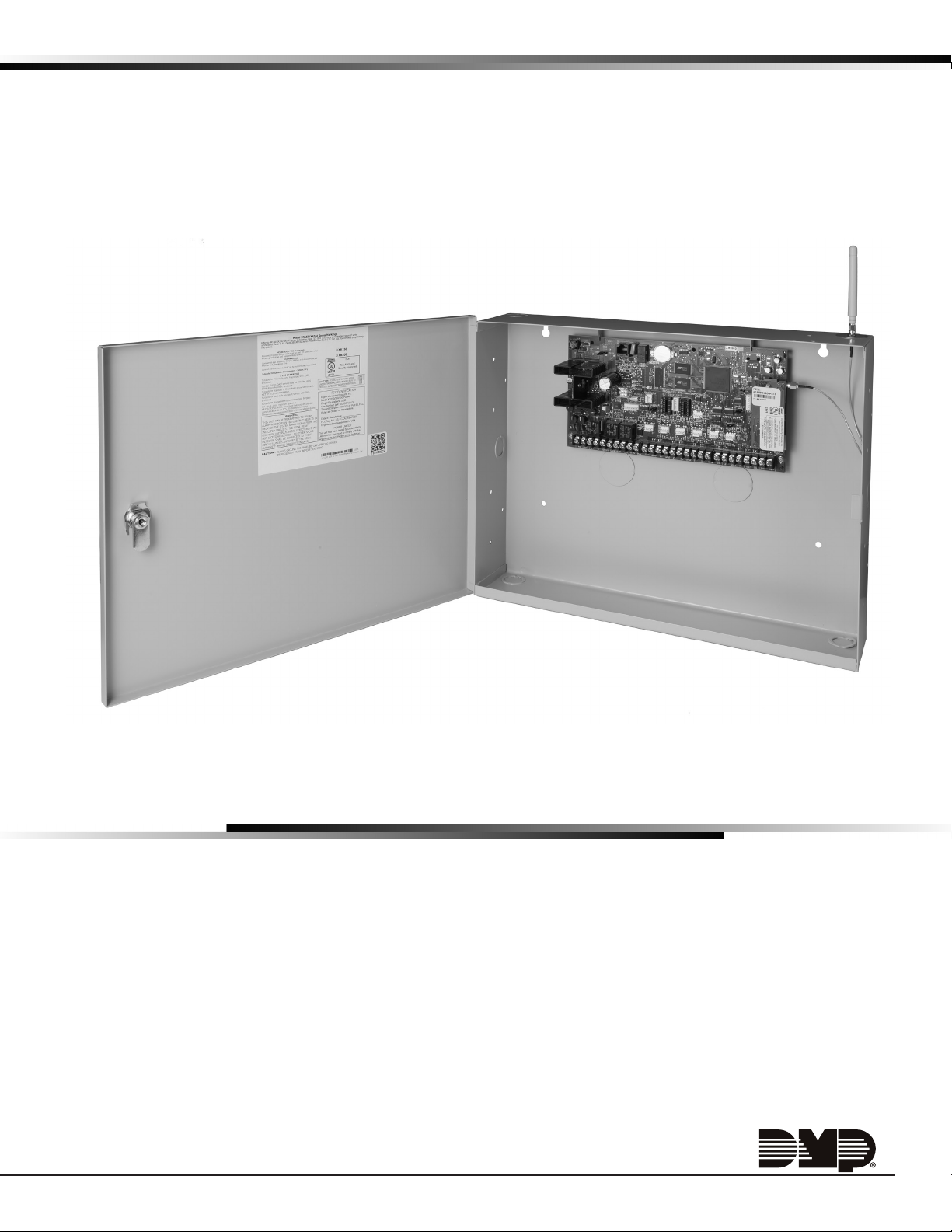
1.7 Enclosure Specications
The XR150/XR550 Series panels are shipped in an enclosure with a transformer, End-of-Line resistors, battery leads,
user’s guide, and programming sheets.
Enclosure
Model
350 17.5”W x 13.5”H x 3.5”D Gray (G) or Red (R) 18-Gauge
350A 17.5”W x 13.5”H x 3.75”D Gray (G) 18-Gauge with 16-Gauge door
341 13.22”W x 7.0”H x 3.5”D Gray (G) 20-Gauge
349 12.5”W x 11.5”H x 3.5”D Gray (G) 20-Gauge
352X 14.5”W x 32.0”H x 4.0”D Gray (G) 16-Gauge
Size Color(s) Construction (Cold Rolled
Steel)
Panel Features
2.1 Description
The DMP XR150/XR550 Series system is made up of an alarm panel with a built-in communicator, an enclosure,
battery, one transformer, and keypads. Each panel is a versatile 12 VDC, combined access control, burglary, and
re communicator panel with battery backup. The panels provide eight on-board burglary zones and two on-board
12 VDC Class B powered zones. The powered zones have a reset capability to provide for 2-wire smoke detectors,
relays, or other latching devices. Combined current requirements of additional modules may require an auxiliary
power supply. Refer to the Power Requirements section in this guide when calculating power requirements. The
panels can communicate to DMP SCS-1R or SCS-VR Receivers using digital dialer, cellular, network, or Contact ID
communication. Panels using cellular, network, or encrypted communication can also communicate to DMP SCS-VR
Receivers.
2.2 Zone Expansion
Each panel provides multiple options for zone expansion:
• 10 on-board zones
• Up to 64 programmable keypad zones
• Up to 500 LX-Bus zones
Using DMP LCD keypad remote zone capability and zone expansion modules, additional zones are available on each
panel:
• XR550 provides up to 574 additional zones
• XR150 provides up to 142 additional zones
The panel keypad data bus supports up to 16 supervised device addresses with each address supporting up to four
programmable expansion zones (64 total).
Using the on board LX-Bus connections, and any combination of single, four, eight, or sixteen-zone expansion
modules and single-zone LX-Bus detectors, additional zones are available on each panel:
• XR550 provides up to 500 additional zones (LX500-LX900)
• XR150 provides up to 100 additional zones (LX500)
Note: Do not use shielded or twisted pair wiring for LX-Bus or Keypad Bus circuits.
2.3 Output Expansion
In addition to the two SPDT relays and four programmable open collector outputs on the XR150/XR550 Series, you
can also connect up to 25 programmable Model 716 Output Expansion Modules to each LX-Bus. These modules can
provide an additional 500 or 100 programmable SPDT relays.
The panels provide Output Schedules for programming the 716 to perform a variety of annunciation and control
functions. Also assign the 716 outputs to any panel Output Options such as Fire Alarm, Communication Fail, or Phone
Trouble Outputs. Refer to the 716 Installation Guide (LT-0183).
The LX-Bus also supports the Model 717 Graphic Annunciator Module. Each 717 module supplies 20 switched ground
outputs that follow the state of their assigned zones.
Note: The 717 supports the rst eight Keypad Bus addresses. To follow Keypad Bus addresses nine through 16, install
multiple 716 modules. Refer to the 717 Installation Guide (LT-0235) and 716 Installation Guide (LT-0183).
Digital Monitoring Products XR150/XR550 Series Installation Guide
2

SYSTEM COMPONENTS
2.4 Central Station Communication
You can program the panel for reporting to DMP SCS-VR or SCS-1R Receivers using digital dialer, cellular, network, or
Contact ID communication. The panels connect at the premises to a standard RJ31X or RJ38X telephone jack. Use
the DMP 893A Dual Phone Line Module when connecting the panel to two separate phone lines in re or burglary
applications.
2.5 Encrypted Communications (XR550 with Network & Encryption Only)
An XR550 panel can communicate using AES encryption. If you currently have an XR550 panel with network
capability, you may contact DMP Customer Service with the panel serial number. The serial number(s) should be sent
in writing via e-mail or fax. A separate feature key is sent for each panel to activate encrypted communications
using the Feature Upgrade process. Encrypted communication cannot be enabled on a XR550 panel without network
communication capabilities. For more information on the Feature Upgrade process see the XR150/XR550 Series
Programming Guide (LT-1232).
Note: 256-bit encrypted messages to SCS-1R receiver only communicate when using SCS-104 Receiver Line Cards
with Version 102 or higher software.
2.6 Caution Notes
Throughout this guide you will see caution notes containing information you need to know when installing the panel.
These cautions are indicated with a yield sign. Whenever you see a caution note, make sure you completely read
and understand its information. Failing to follow the caution note can cause damage to the equipment or improper
operation of one or more components in the system. See the example shown below.
Always ground the panel before applying power to any devices: The panel must be properly grounded
before connecting any devices or applying power to the panel. Proper grounding protects against
Electrostatic Discharge (ESD) that can damage system components.
2.7 Compliance Instructions
For applications that must conform to a local authorities installation standard or a National Recognized Testing
Laboratory certicated system, please see the Compliance Listing Guide LT-1330 for additional instructions.
XR150/XR550 Series Installation Guide Digital Monitoring Products
3
System Components
Ground
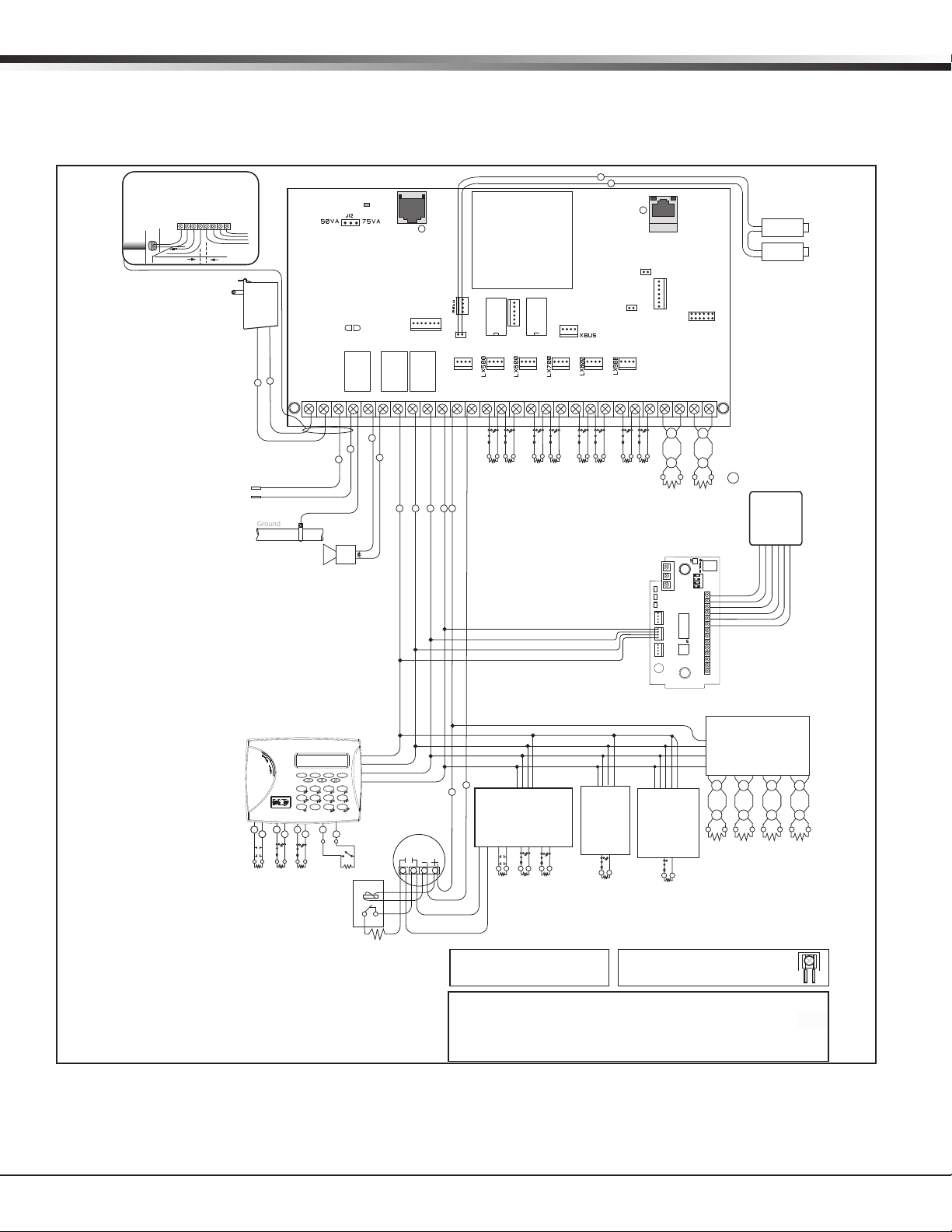
3.1 Wiring Diagram
The XR150/XR550 Series diagram below shows some of the accessory modules you can connect for use in various
applications. A brief description of each module follows in section 3.3.
s
1
2
3
4 5 6 7
8
9
10
11 12 13 14
Front and Rear
tamper protection
included with Model
350 A Attack
Resistant Enclosure.
Front
Tamper
Rear
Tamper
Any other contact
devices listed for Fire
Protective Signaling
can be connected to
zones
9 and 10.
Zones 9 and 10 and
Model 715
compatibility
identifier: A
Maximum operating
range: 13.8 VDC to
9.7 VDC.
Class B (Style A).
Using verification
delays on zones 9
and 10 is optional.
Use the delays
marked on the smoke
detectors.
= Supervised Circuit
Card
Reader
Green (Data 0)
White (Data 1)
Orange
Black
Yellow
Red
AC Wiring must be in conduit and exit out
the left side of the enclosure.
Wiring on terminals 5 through 22 must
exit right and maintain 1/4" separation
from the AC and battery positive wiring.
The plug-in transformer shall
plug into a 120 VAC 60 Hz
outlet not controlled by a
switch and all
wire
16 to 18 gauge
shall run through conduit.
Bell
12 VDC
Minimum cuto time 5 min.
1.5 Amp Max
¼"
Maximum AC Wire distance
with 16 gauge wire: 70 feet
with 18 gauge wire: 40 feet
s
s
AC
16 to 18 gauge wire
RED
BLACK
Earth
Ground
s
Power
LED
s
J3
Phone Line
XR550 Series
Panel
Outputs 3-6
Battery
Start
+B
BELLGND SMK GNDRED YEL GRN BLK Z1 Z2 Z3 Z4 Z5 Z6 Z7 Z8 Z9+ Z9– Z10+ Z10–
AC –B
Form C Relays (J2)
Output Color Code–Model 431 Harness
Output 2 N/O Orange/White
Output 2 Com White/Gray
Output 2 N/C Violet/White
Output 1 N/O Orange
Output 1 Com Gray
Output 1 N/C Violet
Annunciator Outputs (J11)
Output Color Code
Output 3 Red
Output 4 Yellow
Output 5 Green
Output 6 Black
J11
Output 1 Output 2
J10
J4
Tamper
J8 J14
PROG
J2
K6 K7
Out1 Out2
J9 J15
GND GND GNDGND
s
Link LED
J1
Ethernet
Load
Activity
LED
s
J18
J6
J16
J13
Reset
J17
J19
J24
Cell Module
1 2 3 4 5 6 7 8 10 11 12 13 14 15 16 17 18 199 20 21 22 23 24 25 26 27 28
s
s
s
s
Cold Water
Pipe Earth
Ground
1k
Ohm
Bell
Bell cuto time
range is 5 to 99
minutes, non-coded.
22 gauge minimum
22 gauge minimum
22 gauge minimum
22 gauge minimum
s s s s s
RED
BLACK
GREEN
YELLOW
Zone 2
Zone 4
Zone 5
Zone 3
Zone 1
SS
SS
SS
1k
1k
1k
Ohm
Ohm
Total current combined from terminals 7, 11,
25, 27, XBUS and LX500-LX900:
1.5 Amp Max 13.8 VDC to 10.2 VDC
BLACK
GREEN
YELLOW
RED
1k
Ohm
Ohm
Auxiliary/Smoke Power
Zone 6
SS
SS
SS
1k
1k
Ohm
Ohm
Ohm
1k
Zone 7
SS
Ohm
1k
Zone 8
SS
RELAY
ON
READ LED
WIEGAND
XMT LED
DATA
PROG
RED
KYPD IN
RED
KYPD OUT
Resistor
J1
RED
YEL
GRN
RED
Piezo
+ –
Zone 9Zone
S S S S
3.3k
3.3k
Ohm
Ohm
Resistor
DMP
DMP
Model
Model
309
309
NO
S1
C
NC
Interface
Module
734
J2
J4
J5
10
ON
RED
WHTGRN BLK Z1 Z2 Z3 Z4+ Z4–RA GND GND
LC AS
J3
Zone Expander
Model 715
7mA @ 12 VDC
Models 715-8, 715-16
20mA @ 12 VDC
S S S S S S S S
3.3k Ohm 3.3k Ohm 3.3k Ohm 3.3k Ohm
Listed Resistors
1.0k Ohm - DMP Model 311
3.3k Ohm - DMP Model 309
10K Ohm - DMP Model 308
sss
sss
1k Ohm 1k Ohm
s s
1k Ohm
s s
s
DISARM
ARM
Keyswitch Arming
can be connected
to any zone.
Smoke
Detector
1k Ohm
AUXILIARY/SMOKE POWER
RED
YELLOW
GREEN
BLACK
s
s
Zone Expander
Model 714
7 mA @ 12 VDC
Models 714-8, 714-16
20mA @ 12 VDC
1k Ohm 1k Ohm 1k Ohm
S SS SS S
Zone
Expander
Model 711
7 mA @
12 VDC
S S
1k Ohm
Zone
Expander (up
to 8 zones)
Model 712-8
19 mA @
12 VDC
S S
1k Ohm
Intended Installation Environment - Indoor/Dry
WARNING: Incorrect connections
may cause damage to the unit.
THIS UNIT MAY BE PROGRAMMED TO USE AN ALARM VERIFICATION FEATURE THAT
RESULTS IN DELAY OF THE SYSTEM ALARM SIGNAL FROM THE INDICATED CIRCUITS.
THE TOTAL DELAY (CONTROL UNIT PLUS SMOKE DETECTORS) SHALL NOT EXCEED 60
SECONDS. NO OTHER SMOKE DETECTOR SHALL BE CONNECTED TO THESE CIRCUITS
UNLESS APPROVED BY THE LOCAL AUTHORITY HAVING JURISDICTION (AHJ).
CAUTION: DO NOT USE LOOPED WIRE
UNDER TERMINALS. BREAK WIRE RUN TO
PROVIDE SUPERVISION OF CONNECTIONS.
WARNING
Figure 1: XR550 Series Wiring Diagram
3.2 Lightning Protection
Metal Oxide Varistors and Transient Voltage Suppressors help protect against voltage surges on panel input and output
circuits. Additional surge protection is available by installing the DMP 370 or 370RJ Lightning Suppressors or Model 270
Network Transient Suppression Module.
Digital Monitoring Products XR150/XR550 Series Installation Guide
4

SYSTEM COMPONENTS
3.3 Accessory Devices
Cellular Communicator Cards
263LTE Cellular Communicator Allows you to connect the XR150/XR550 Series to the LTE network.
263LTE-FN Cellular Communicator Provides wireless communication for XR Series panels and is approved for use on FirstNet.
Accessory Modules
270 Network Transient
Suppression Module
277 Trouble Sounder Provides local sounder for monitoring of panel operations and loss of Keypad Bus.
370/370RJ Lightning Suppressor Provides protection against voltage surges on panel input and output circuits.
893A Dual Phone Line Module Allows you to supervise two standard phone lines connected to an XR150/XR550 Series
Expansion Modules
710 Bus Splitter/Repeater Allows you to increase keypad or LX-Bus wiring distance to 2500 feet.
711 Zone Expansion Module Increases available reporting zones. Provides one Type A Class B zone.
711S Zone Expansion Module Provides one Class B zone for connecting burglary devices.
712-8 Zone Expander Provides Class B zones for connecting burglary devices.
714, 714-8, 714-16 Zone Expanders Provides Class B zones for connecting burglary and non-powered re devices.
714N-POE Provides four zones using IP network capability. Compatible with 1k-10k resistors.
715, 715-8, 715-16 Zone Expanders Provides 12VDC Class B powered zones for connecting smoke detectors, glassbreak
716 Output Expander Provides four Form C relays (SPDT) and four switched grounds (open collector) for use in a
717 Graphic Annunciator Module Provides 20 zone following annunciator outputs (open collector) for use in a variety of
7
34, 734N, 734N-POE Access
Control Modules
Wi-Fi™ Module
763 Module Allows you to add Wi-Fi alarm signal communication to XR150 Series with Version 112 or
DMP Two-Way Wireless Devices
1100X Series/1100XH Series
Receiver
1100R Repeater Provides additional range for wireless devices.
1100T Wireless Translator Allows non-DMP wireless devices to integrate with DMP XR150/XR550 Series panels.
1101 Universal Transmitter Provides both internal and external contacts that may be used at the same time to yield two
1102 Universal Transmitter Provides an external contact.
1103 Universal Transmitter Provides both internal and external contacts that may be used at the same time to yield two
1106 Universal Transmitter Provides both internal and external contacts that may be used at the same time to yield two
1107 Micro Window Transmitter Provides a wireless window transmitter.
1108 Wireless Doorbell Module Monitors doorbell presses.
1114 Four-Zone Expander Provides four wireless zones.
1115 Wireless Temperature Sensor
and Flood Detector
1116 Relay Output Provides one Form C relay.
1117 LED Annunciator Provides a visual system status indicator.
1118 Remote Indicator Light Provides a visual indication of a Panic situation.
1119 Door Sounder Provides a battery powered sounder.
1122 PIR Motion Detector Provides motion detection with pet immunity.
1126R Motion Detector Ceiling mount motion detector with panel programmable sensitivity and Disarm/Disable
1127C/1127W PIR Motion Detector Wall mount motion detector with panel programmable sensitivity and Disarm/Disable
1128 Wireless Glassbreak Detector Provides fully-supervised, low current shock and glassbreak detection coverage up to 20 ft.
XR150/XR550 Series Installation Guide Digital Monitoring Products
Provides transient surge protection for the ETHERNET Connector.
panel. The 893A module monitors the main and backup phone lines for a sustained voltage
drop and alerts users when the phone line is bad.
detectors, and other 2- or 4-wire devices.
variety of remote annunciation and control applications for use on the LX-Bus only.
remote annunciation and control applications for use on the LX-Bus only.
Provides system codeless entry, and arming and disarming using access control readers.
higher rmware and Level F hardware and XR550 Series panels with Version 112 or higher
rmware.
Supports up to 100 devices on XR150 panels and 500 devices on XR550 panels in residential
or commercial wireless operation.
individual reporting zones from one wireless transmitter.
individual reporting zones from one wireless transmitter. Requires EOL resistor for external
contact. Provides Disarm/Disable functionality.
individual reporting zones from one wireless transmitter.
Temperature and ood detector wth an internal temperature sensor. Can be paired with
470PB or T280R remote sensors.
functionality.
functionality.
5

1131 Recessed Contact Provides a recessed contact option for door or window applications.
1135 Wireless Siren Provides a wireless siren.
1136 Remote Chime Multi-function sounder that plugs directly into a standard 110VAC wall outlet.
1137 Wireless LED Emergency Light Provides path lighting in the event of an alarm or trouble such as Burglary Alarm Output or
can be activated simultaneously by the panel via the Trip with Panel Bell feature.
1139 Bill Trap Provides a silent alarm option for retail and banking cash drawers.
1141 Wall Button One button wall mounted wireless transmitter.
1142 Two-button Panic Transmitter
1142BC Two-button Panic Belt Clip
Transmitter
1144 Series Wireless Key Fobs 1144 Series Key Fob transmitters designed to clip onto a key ring or lanyard.
1148 Personal Pendant A one-button, wireless emergency transmitter designed to be worn as a wristband or on a
1154 4-Zone Takeover Module Converts up to four existing normally closed, hardwired zones into wireless zones.
1158 8-Zone Input Module Converts up to 8 existing hardwired zones into wireless zones.
1164/1164NS Wireless Synchronized
Smoke Detector
1166 Wireless Smoke Ring Installs on any tradational AC-powered, three wire, interconnected smoke alarm system.
1183-135F Heat Detector Fixed temperature heat detector.
1183-135R Heat Detector Fixed temperature and rate-of-rise heat detector.
1184 Carbon Monoxide Detector Carbon monoxide detector.
Provides permanently mounted under-the-counter two-button panic operation.
Provides portable two-button panic operation.
break-away lanyard. The 1148 may be used to activate an event at the receiver.
Commercial or residential, battery powered, wireless, low prole, photoelectric smoke
detector, with or without synchronizing sounder.
Interface Modules
736P Radionics™ Popit Interface Allows a Radionics™ POPIT System to interface with DMP XR150/XR550 Series panels while
maintaining Radionics™ wiring.
738A Ademco Interface Allows Ademco™ 5881 wireless receivers to interface with DMP XR150/XR550 Series panels.
738I ITI Interface Module Allows ITI™ SuperBus™ 2000 Series wireless receivers to interface with DMP XR150/XR550
Series panels.
738Zplus Z-Wave Interface Module Provides connection for Z-Wave modules.
Indicating and Initiating Devices
860 Relay Module Provides dry relay contacts that are programmable and controlled from the DMP panel
annunciator outputs. Includes one Form C (SPDT) relay rated 1 Amp @ 30VDC. Sockets are
provided to allow the addition of three Model 305 plug-in relays. These relays can be used
for electrical isolation between the alarm panel and another system or switching 5, 12, or
24 Volts to control various functions within a building or around its perimeter.
865 Supervised Style W or X
Notication Circuit Module
866 Style W Notication Circuit
Module
867 Style W LX-Bus Notication
Circuit Module
869 Dual Class A Style D Initiating
Module
Provides supervised alarm current when using the XR150/XR550 Series panel bell output
and up to 5 Amps at 12 or 24VDC when using a listed auxiliary power supply. The 865
can supervise 2-wire or 4-wire style circuits for opens and shorts with individual LED
annunciation.
Provides supervised alarm current using the XR150/XR550 Series panel bell output and up
to 5 Amps at 12 or 24VDC when using a listed auxiliary power supply. The 866 can supervise
2-wire Style W circuits for opens and shorts.
Provides supervised alarm current using the XR150/XR550 Series panel bell output and up to
5 Amps at 12 or 24VDC when using a listed auxiliary power supply. The 867 connects to the
XR150/XR550 Series panel LX-Bus and provides one 2-wire Style W notication circuit for
open and short conditions. Individual Bell Relay addresses Bell Ring styles.
Provides two Class A, Style D, 4-wire initiating zones for connecting waterow switches and
other non-powered re and burglary devices.
Keypads
LCD keypads Allows you to control the panel from various remote locations. Connect up to sixteen Model
630F Remote Fire Command Center, Model 7060, 7063, 7070, 7073, 7160, 7163, 7170, 7173
Thinline™ keypads, or 7060A, 7063A, 7070A, 7073A Aqualite™ keypads to the keypad bus
using terminals 7, 8, 9, and 10.
7800 Series
keypads
9000 Series Wireless keypads Allows you to control the panel from various remote locations. Connect up to seven
9800 Series Wireless
Touchscreen Keypad
Graphic Touchscreen
Graphic
Allows you to control the panel from various remote locations. Connect up to sixteen Model
7872 or 7873 Graphic Touchscreen keypads to the keypad bus using terminals 7, 8, 9, and 10.
9060/9063 Wireless Keypads.
Allows you to control the panel from various remote locations. Associate up to seven 9862
Wireless Graphic Touchscreen Keypads.
Addressable Smoke Detectors
2W-BLX, 2WT-BLX Single-zone, addressable conventional smoke, smoke/heat detectors that connect to the LX-
Bus. Includes drift compensation.
Digital Monitoring Products XR150/XR550 Series Installation Guide
6
 Loading...