

Page 1
265LTE TOUCH SERIES
CELLULAR COMMUNICATOR
Installation Guide
INSTALL THE 265LTE TOUCH SERIES
XTLtouch
1
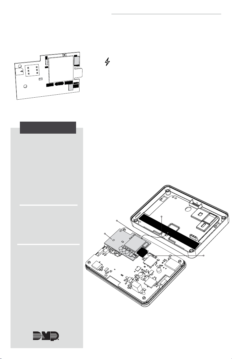
Figure 1: 265LTE Touch Series PCB
DESCRIPTION
The 265LTE Touch Series
Cellular Communicator
provides a fully-supervised
alarm communication path
over the LTE network.
The 265LTE Touch Series is
installed on the XTLtouch and
powered by the panel so no
additional enclosure, power
supply, or battery back-up is
needed.
Caution: Touch grounded metal to discharge static
before handling the PCB.
1. Gently remove the back cover and disconnect the
battery from the XTLtouch.
2. Remove the four screws located in each corner of
the XTLtouch housing.
3. Insert the 265LTE into the eight-pin cell module
header, keeping it parallel to the PCB.
4. Snap the 265LTE onto the PCB stando and secure
it in place.
5. Remove the backing from the flexible antenna and
place it inside the housing cover. See Figure 2.
6. Snap the antenna on to the 265LTE on-board
antenna connector.
7. Carefully replace the housing cover, ensuring the
antenna stays in contact with the 265LTE on-board
antenna connector.
8. Use the four screws to secure the housing cover.
9. Reconnect the battery to return power to the
XTLtouch.
Compatibility
• XTLtouch (Version 183
and higher)
What is Included?
• 265LTE Touch Series
Cellular Communicator
• Flexible Antenna
On-board
Antenna
Connector
Stando
Figure 2: Installing the 265LTE Touch Series
Flexible Antenna
on the XTLtouch
Cell Module
Header
Page 2

ACTIVATE THE 265LTE TOUCH SERIES
Cellular service is required before using the 265LTE for signal transmission. The 265LTE
2
comes ready for activation with SecureComTM Wireless. Use Remote LinkTM, Dealer AdminTM
(dealer.securecomwireless.com), the Tech APPTM, or call DMP Customer Service
(1-866-266-2826) to activate the 265LTE.
Remote Link
1. Navigate to Remote Link and select a panel.
2. Select Program in the top menu and select Communications from the drop-down
menu.
3. Select Cellular Network as the Communication Type and click Activate.
4. Select SIM as the SIM Type.
5. Enter the SIM number found on the 265LTE label and click Activate.
6. Select a Rate Plan for the 265LTE and click Activate.
Dealer Admin
1. Navigate to the Dealer Admin site (dealer.securecomwireless.com).
2. Click Customers in the right-side menu and select a customer.
3. Click Add System.
4. Enter a System Name.
5. Select XTLplus from the System Type drop-down menu.
6. Select either Cellular or EASYconnect + Cell Backup in the Connection Type field.
7. Enter the SIM number found on the 265LTE label and click Get Status.
8. Enter the Account Number.
9. Select a Rate Plan for the 265LTE.
10. Click Activate Cellular Device.
Tech APP
1. Navigate to the Tech APP.
2. Tap Find a Customer then search for a customer.
3. Tap Add a System.
4. Enter a System Name.
5. Scan or enter the Serial #.
6. Select XTLplus from the System Type drop-down menu.
7. Select either Cellular or EASYconnect + Cell Backup in the Connection Type field.
8. Enter the Account Number.
9. Enter the SIM number found on the 265LTE label, then tap Get SIM Status.
10. Select a Rate Plan for the 265LTE.
11. Tap Activate Cellular Device.
265LTE Touch Series Installation Guide | Digital Monitoring Products, Inc 2
Page 3

TEST THE 265LTE TOUCH
The panel provides a diagnostic function to test the communication integrity and cellular
signal strength of the 265LTE to the nearest tower for the cellular carrier. To use the
3
diagnostic function, reset the panel, enter 2313 (DIAG), and press CMD.
Communication Status
This option tests the individual components of cellular or wireless network communication.
1. Select CELL STATUS from the diagnostic menu. Possible test results are shown in
Table 1.
2. Select YES to continue through the remaining component tests or select NO to
stop testing and return to CELL STATUS.
Confirmed Faulty
MODEM OPERATING NO MODEM FOUND
IDENTIFIED NO SIM CARD
TOWER DETECTED NO TOWER
REGISTERED NOT REGISTERED
CONNECT SUCCESS
CELL PATH GOOD NO ACK RECEIVED
Table 1: Communication Test Results
Cellular Strength
This option provides a way to test the cellular signal strength of the nearest tower for the
cellular carrier. Follow the steps below to test the cellular strength of the 265LTE:
1. Select CELL SIGNAL from the diagnostic menu then press a select key or area.
2. SIGNAL: displays. The numerical value of the cell signal strength is represented
in -dBm. The bars represent the signal strength of the 265LTE and range from 0-7.
Zero bars indicate a weak signal and seven bars indicate a strong signal.
CONNECT ERROR
NOT ACTIVATED
3 265LTE-V-TOUCH Installation Guide | Digital Monitoring Products, Inc.
Page 4
FCC INFORMATION
This device complies with Part 15 of the FCC Rules. Operation is subject to the following two conditions:
1. This device may not cause harmful interference, and
2. this device must accept any interference received, including interference that may cause undesired
operation.
The antenna used for this transmitter must be installed to provide a separation distance of at least 20 cm
(7.874 in.) from all persons. It must not be located or operated in conjunction with any other antenna or
transmitter.
Changes or modifications made by the user and not expressly approved by the party responsible for
compliance could void the user’s authority to operate the equipment.
Note: This equipment has been tested and found to comply with the limits for a Class B digital device,
pursuant to part 15 of the FCC Rules. These limits are designed to provide reasonable protection against
harmful interference in a residential installation. This equipment generates, uses and can radiate radio
frequency energy and, if not installed and used in accordance with the instructions, may cause harmful
interference to radio communications. However, there is no guarantee that interference will not occur
in a particular installation. If this equipment does cause harmful interference to radio or television
reception, which can be determined by turning the equipment o and on, the user is encouraged to try
to correct the interference by one or more of the following measures:
• Reorient or relocate the receiving antenna.
• Increase the separation between the equipment and receiver.
• Connect the equipment into an outlet on a circuit dierent from that to which the receiver
is connected.
• Consult the dealer or an experienced radio/TV technician for help.
Industry Canada Information
This device complies with Industry Canada Licence-exempt RSS standard(s). Operation is subject to the
following two conditions:
1. This device may not cause interference, and
2. this device must accept any interference, including interference that may cause undesired operation
of the device.
This system has been evaluated for RF Exposure per RSS-102 and is in compliance with the limits specified
by Health Canada Safety Code 6. The system must be installed at a minimum separation distance from the
antenna to a general bystander of 7.87 inches (20 cm) to maintain compliance with the General Population
limits.
Le présent appareil est conforme aux CNR d’Industrie Canada applicables aux appareils radio exempts de
licence. L’exploitation est autorisée aux deux conditions suivantes:
1. l’appareil ne doit pas produire de brouillage, et
2. l’utilisateur de l’appareil doit accepter tout brouillage radioélectrique subi, même si le brouillage est
susceptible d’en compromettre le fonctionnement.
L’exposition aux radiofréquences de ce système a été évaluée selon la norme RSS-102 et est jugée conforme
aux limites établies par le Code de sécurité 6 de Santé Canada. Le système doit être installé à une distance
minimale de 7.87 pouces (20 cm) séparant l’antenne d’une personne présente en conformité avec les limites
permises d’exposition du grand public.
265LTE TOUCH SERIES
CELLULAR COMMUNICATOR
Specifications
Primary Power 12VDC
Current Draw
Standby 13mA
Alarm 13mA
Ordering Information
265LTE-V-Touch Cellular Communicator for Verizon LTE
265LTE-A-Touch Cellular Communicator for AT&T LTE
Compatibility
XTLtouch Series Panels
Designed, engineered, and
manufactured in Springfield, Missouri
using U.S. and global components.
© 2021 Digital Monitoring Products, Inc.
LT-1703-TOUCH 21123
Certifications
Cellular FCC Part 15: XMR201707BG96
Industry Canada: 10224A-201709BG96
Intertek (ETL) Listed
• ANSI/UL 985 Contol Units and Accessories,
Household System Type
(Residential Fire)
• ANSI/UL 1023 Household Burglar Alarm
System Units (Residential
Burglary)
• ANSI/UL 1610 Central Station Alarm Units
(Commercial Burglary)
• ANSI/UL 1635 Digital Alarm Communicator
System Units (Commercial
Burglary)
INTRUSION • FIRE • ACCESS • NETWORKS
2500 North Partnership Boulevard
Springfield, Missouri 65803-8877
888.436.7832 | DMP.com
 Loading...