

Page 1
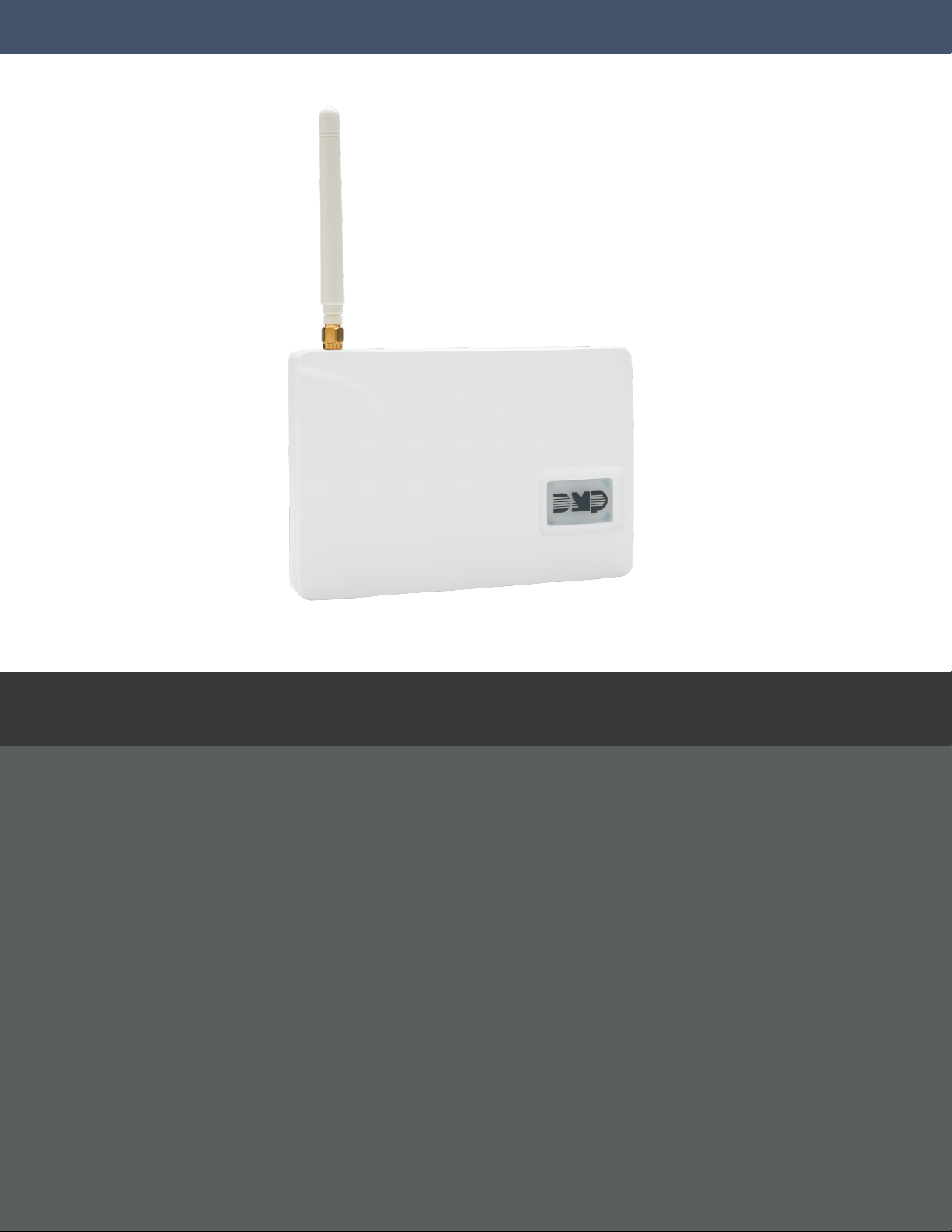
PROGRAMMING AND INSTALLATION GUIDE
DualCom™ Series Universal Alarm Communicator
Digital Monitoring Products, Inc.
© 2021
Page 2

TABLE OF CONTENTS
About the Communicator ......................1
System Components ...............................1
Terminals.......................................................................1
Programming (PROG) Connection ....................2
Tamper...........................................................................2
Reset Button ...............................................................2
Load Button ................................................................2
Backlit Logo ................................................................3
ECP and DSC Passthru ............................................3
Installation ...............................................4
Select a Location .......................................................4
Mount the Communicator ......................................4
Wire the Communicator .........................................5
Connect the Antenna ..............................................5
Applications .............................................6
CID Dialer Connection .............................................6
Communication Failure (DualComNF only) ...6
Zones 1‑4 Input Connection ..................................6
Zone4 Bell Connection ..........................................7
ECP Passthru Connection ......................................9
DSC Passthru Connection ......................................11
Arming and Disarming ...........................12
Use the Virtual Keypad App .................................12
Use Outputs ................................................................12
Initialization .............................................18
Clear All Codes ..........................................................18
Clear All Schedules ...................................................18
Clear Events ................................................................18
Clear Zone Programming .......................................18
Clear Communication ..............................................18
Set to Factory Defaults ...........................................18
Communication .......................................19
Account Number .......................................................19
Transmission Delay ...................................................19
Communication Type ..............................................19
Backup Cell ..................................................................19
Test Time ......................................................................19
Net/Cell Test Days ....................................................19
Check‑In Minutes .......................................................19
Fail Time Minutes ......................................................19
Backup Check‑In Minutes ......................................19
Backup Fail Time Minutes ......................................19
Receiver1 Programming .........................................20
Receiver2 Programming ........................................21
Network Options .....................................22
Wi‑Fi Setup..................................................................22
WPS ................................................................................22
List ..................................................................................22
Activate the Cellular Module .................14
Dealer Admin Activation ........................................14
Tech APP Activation ................................................14
Remote Link Activation ..........................................14
Programming ...........................................15
Before You Begin ......................................................15
Getting Started ..........................................................15
Programming Menu ..................................................15
Reset Timeout ............................................................16
Special Keys ................................................................16
Letters and Special Characters............................17
Current Programming .............................................17
Manual ...........................................................................22
Test .................................................................................23
Wireless Security Type ............................................23
Wireless Network Key .............................................23
DHCP Mode Enabled ...............................................23
Local IP Address ........................................................23
Gateway Address ......................................................23
Subnet Mask ................................................................23
DNS Server ..................................................................23
Programming Port ....................................................23
Remote Options ......................................24
Remote Key .................................................................24
Remote Disarm ..........................................................24
App Key ........................................................................24
Page 3

System Reports .......................................24
Opening/Closing Reports ......................................24
Zone Restoral Reports ............................................24
System Options .......................................25
Entry Delay 1 ...............................................................25
Exit Delay .....................................................................25
Cross Zone Time ........................................................25
Power Fail Delay ........................................................25
Swinger Bypass Trips ..............................................25
Reset Swinger Bypass .............................................25
Time Changes .............................................................26
Hours from GMT .......................................................26
Keypad Input ..............................................................26
CID Format ..................................................................26
Zone Number ..............................................................31
Stop ........................................................... 32
Set Lockout Code ...................................32
Stop ................................................................................32
Set Lockout Code .....................................................32
Z‑Wave Setup (DualComWZ Only) ................... 33
Add Z‑Wave Devices (ADD) .................................33
List Z‑Wave Devices (LIST) ...................................33
Rename Z‑Wave Devices .......................................33
Status of Z‑Wave Devices ......................................34
Remove Z‑Wave Devices (REMOVE) ................34
Favorites (FAV) ..........................................................34
Adding a Favorite .....................................................34
Add Devices to Favorites .......................................34
Output Options .......................................27
Cutoff Outputs ...........................................................27
Output Cutoff Time ..................................................27
Communication Failure Output ...........................27
Armed Output ............................................................27
Remote Arming Output ..........................................27
Heat Saver Temperature ........................................27
Cool Saver Temperature ........................................27
Area Information .....................................28
Area Number ..............................................................28
Area Name ...................................................................28
Automatic Arming ....................................................28
Automatic Disarming ...............................................28
Zone Information ....................................29
Zone Number ..............................................................29
Zone Name ..................................................................29
Zone Type ....................................................................29
Next Zone .....................................................................30
Alarm Action ...............................................................30
Disarmed Open ..........................................................30
Message To Transmit................................................30
Output Number .........................................................30
Output Action.............................................................31
Swinger Bypass .........................................................31
Cross Zone ...................................................................31
Change Device Settings in Favorites.................35
Edit Devices in Favorites ........................................35
Remove Devices from Favorites ..........................35
Transfer Controller (XFER) ....................................36
Optimize (OPT) ..........................................................36
Appendix ..................................................37
ECP Passthru .............................................................37
DSC Passthru ..............................................................37
False Alarm Reduction ............................................37
Diagnostics Function ...............................................38
Using the 984 Command Function ....................39
NET .................................................................................39
CELL ...............................................................................39
Using the Walk Test ..................................................39
Walk Test ......................................................................39
Trip Counter for Walk Test (STD) ........................39
Test End Warning ......................................................39
Failed Zones Display ................................................39
Cross Zoning ...............................................................40
Z‑Wave Information (DualComWZ only) ..............40
Arming/Disarming Ademco Vista Panels ........41
FCC NOTICE .............................................42
Industry Canada ......................................42
NFPA 72 ....................................................42
Receiver Routing .......................................................31
Page 4

Page 5

ABOUT THE COMMUNICATOR
The DualCom™ communicator provides a fully supervised alarm communication path and integrated primary and
secondary communication on one PCB. For commercial fire or residential fire installations, DualComNF modules
feature primary network communication, secondary cellular communication, and two sets of tip and ring terminals.
For non‑fire residential installations, DualComWZ modules feature built‑in primary Wi‑Fi communication, secondary
cellular communication, Z‑Wave integration, and one set of tip and ring terminals.
Use the DualCom communicator to take over panels. The communicator can be connected to a control panel’s dialer
output and used to capture Contact ID messages based on SIA DC‑05‑1999.09‑DCS.
The communicator also provides four input zones and two open‑collector outputs for connection to control panel
outputs and zones. Connect to the bell output of an existing control panel using zone4 on the communicator. The
communicator operates in a variety of applications: CID Dialer Connection, Zones1‑4 Input Connections, or Zone4
Bell Connection. See Applications.
DualComNF modules include a red enclosure and a Model 685‑R (Red) Backbox.
Features
• Can be powered from 12VDC or 24VDC
• Zone1‑4 terminals with 12V and 24V power input
• EASYconnect™
• 2sets of tip and ring terminals (DualComNF only)
• 1set of tip and ring terminals (DualComWZ only)
• Programming header for connecting to a programming keypad
• LED to indicate armed state
What is Included
• PCB with enclosure
• Model685‑R Backbox (DualComNF only)
• Hardware pack
• External antenna
SYSTEM COMPONENTS
Terminals
Power Connection Terminals
The communicator may be powered from the 12VDC or 24VDC auxiliary output of the control panel. Observe
polarity and use 18‑22 AWG wire to connect the
on the
terminal on the control panel auxiliary output.
control panel auxiliary output
. See Figure 1. Connect the communicator terminal G(ground) to the negative
Control Panel Standby Power
During a power outage, the communicator draws power from the control panel’s backup battery. The communicator
must be included in the standby battery calculations for the control panel.
Zones 1‑4
Terminals Z1 to Z3, G(ground), Z4+ and Z4‑ provide four zones to connect to individual relay outputs on the control
panel. Zone4 (Z4+ and Z4‑) can be connected to the control panel bell output. See Zone4 Bell Connection.
Open‑Collector Outputs
Terminals O1 and O2 can be programmed to indicate the activity of the zones or conditions occurring on the system.
Open‑Collector outputs do not provide a voltage but instead switch‑to‑ground the voltage from another source.
Maximum voltage is 30VDC at 50mA. The outputs can respond to any of the conditions listed below:
• Activation by zone condition: Steady, Pulse, Momentary, or Follow
• Communication
• Armed area annunciation
• Remote Arming Output
communicator terminal +12 to the +12 or +24V positive terminal
Dialer Connection
Directly connect the Telco phone line (tip and ring) from the control panel to the terminalR(Ring) and one into
terminalT(Tip). For more information, refer to “CID Dialer Connection”.
DualCom
Programming and Installation Guide Digital Monitoring Products
1
Page 6

Programming (PROG) Connection
A 4‑pin programming header is provided to connect a keypad when using a DMP Model330 programming cable.
This provides a quick and easy connection for programming the communicator. For 24VDC applications using the
communicator, connect the keypad using a Model330‑24 4‑wire programming harness with an in‑line resistor. After
programming is complete, remove the keypad.
Caution: If connecting to a 24VDC control panel, do not connect a keypad using a Model330 harness.
Tamper
The tamper is pressed when the cover of the communicator is secured onto the enclosure. When the cover is
removed, the communicator sends a tamper trouble message to the central station.
Reset Button
The reset button is located on the upper right side of the circuit board and is used to reset the communicator. After
resetting the communicator, begin programming within 30minutes. If you wait longer than 30minutes, reset the
communicator again.
Note: After the panel is reset, cell suppression is disabled for 30 minutes.
Load Button
Firmware can be updated with the programming header. Firmware updates are available for download, free of charge,
on the DMP Dealer Direct website at DMP.com/Dealer_Direct.
Caution: Do not connect a Model401 to the communicator if using 24V power.
Performing a Firmware Update
To update the communicator with a new firmware version, complete the following steps at the protected premise:
399 Programming Cable
1. Connect a DMP 399 Cable from the programming header to the serial port of your PC operating RemoteLink
and containing the communicator RU file.
2. Start RemoteLink and create or open the account that matches the communicator to be updated.
3. Set the connection information type to direct with a baud rate of 38400 and choose the appropriate COM port.
4. Select Panel > Remote Update, then select the correct RU file for the communicator.
5. Press and hold the load button, then press and release the reset button.
6. Release the load button and select <Update> in Remote Link.
7. After the firmware update is completed, remove the 399 cable and press the reset button to resume normal
operation.
Model401 USB Flash Module
When loading the firmware RU file onto a USB drive, place the file in the root directory of the USB drive. The update
cannot be inside a folder. Format the USB drive as FAT32.
Place only one firmware file in the root directory. If more than one RU file exists on the USB drive, the communicator
will choose the RU file with the most recent date modified.
Caution: DualCom, CellCom, iCom, and XTL+ do not use the same RU files. Using the wrong RU file for the update
will cause the communicator to stop working until the correct RU file is used to flash the firmware.
1. Connect the USB flash drive to the Model401.
2. Press and hold the reset button on the communicator. You will continue to hold reset until step 6.
3. Connect the assembly to the communicator’s programming header.
4. Press and release the button on the Model401.
5. With your finger still on RESET, press and hold the load button. Continue to hold LOAD until step 8.
6. Release the reset button.
7. Press and release the button on the Model401.
8. When the green LED on the Model401 starts a slow flash, release the load button. The slow flash will last
5minutes, then the green LED will become steady, indicating the firmware version is updated.
Note: If the LED blinks rapidly, the update was unsuccessful. Press and release RESET. Begin again at step1
9. Press and hold RESET. Remove the Model401, then release RESET to resume normal operation.
In the event the Model401 USB Flash Module is inadvertently removed from the communicator before the update
finishes, repeat steps1‑9.
Digital Monitoring Products
2
DualCom
Programming and Installation Guide
Page 7
Backlit Logo
The backlit logo indicates the power and armed status of the communicator. Depending on the operation, the LED
displays in red or green as listed in the Table 1. The LED indicates the armed state and status of the system primary
power.
COLOR AND ACTIVITY OPERATION
Green Steady Communicator Disarmed, Primary Power OK
No Light No Power
Red Steady Communicator Armed, Primary Power OK
Table 1: LED Status
ECP and DSC Passthru
Perform an ECP or DSC Passthru and communicate through the communicator over the host panel’s bus. This
also allows users to manage host panels through Virtual Keypad including arming, disarming, viewing zone status,
bypassing zones, view history, manage users, and more.
Note: Programming a DSC panel remotely requires a Model 330‑DSC Programming Harness (sold separately).
DualCom
Programming and Installation Guide Digital Monitoring Products
3
Page 8
INSTALLATION
D
Select a Location
Install the communicator away from metal objects. Do not mount the communicator inside or on a control panel metal
enclosure. Mounting the communicator on or near metal surfaces impairs cellular performance.
Mount the Communicator
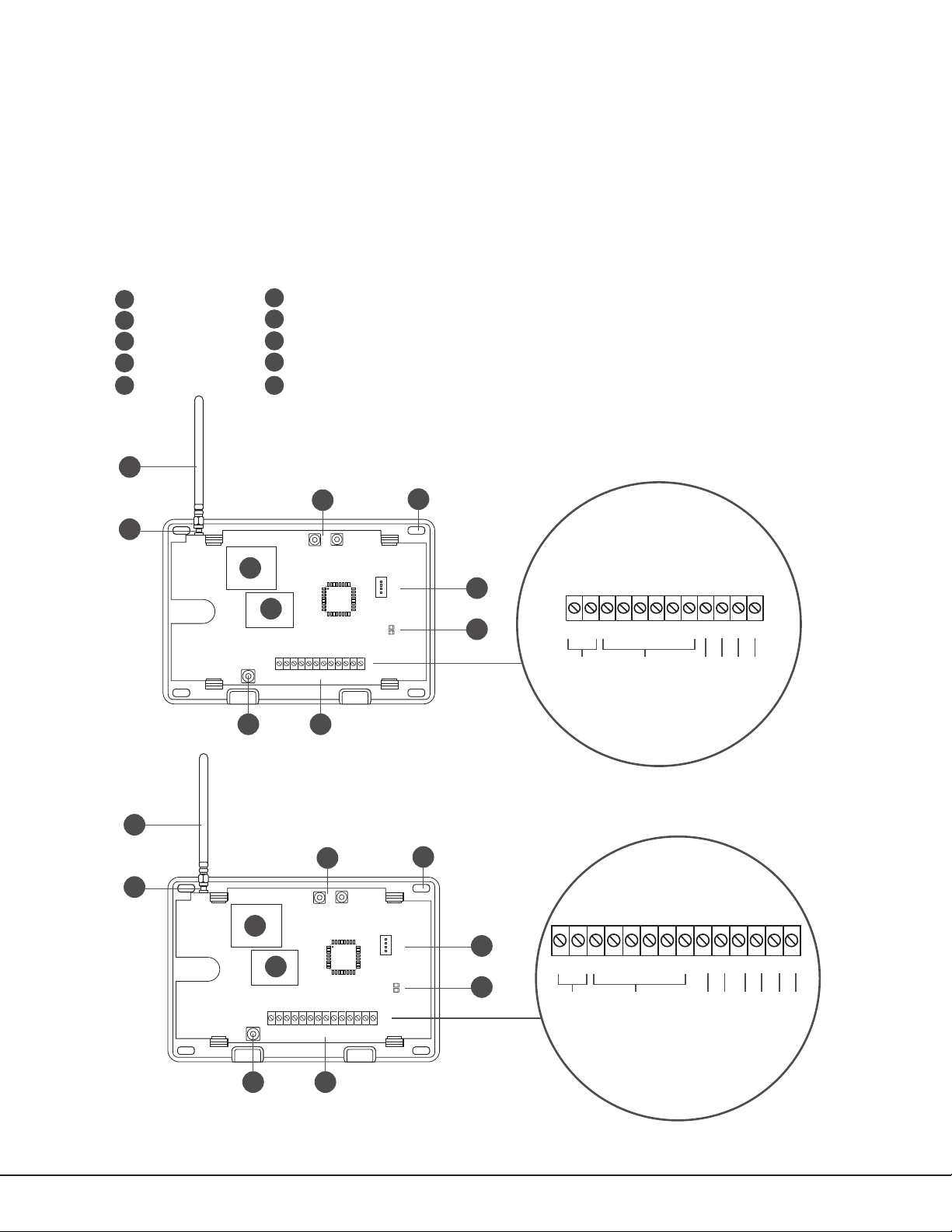
The communicator should be mounted to a wall using the included #6 screws in the mounting holes. See Figure 1.
Mount the communicator in a secure, dry place to protect the communicator from damage due to tampering or the
elements. It is not necessary to remove the PCB when installing the communicator.
Mounting Holes
A
Cellular Antenna
B
SMA Connector
C
Cell Modem
D
Ethernet
E
B
C
D
Tamper
F
Terminal Block
G
Programming Connection
H
Power and Armed LEDs
I
Load and Reset Buttons
J
J
RESETLOAD
E
+Z4-
+DC- Z1 Z2 Z3
T
O1 O2
G
GF
DualCom
A
BR
PROG
R
H
I
+DC- Z1 Z2 Z3
DC Power
+Z4-
G
Zones 1 - 4
O1 O2
Output 1
T R
Tip 1
Ring 1
Output 2
B
C
Digital Monitoring Products
4
D
E
+DC- Z1 Z2 Z3 G T1 R1 T2+Z4- R2O1 O2
DualComNF
J
RESETLOAD
A
BR
PROG
H
+DC- Z1 Z2 Z3 G T1 R1 T2+Z4- R2O1 O2
I
DC Power
Zones 1 - 4
Output 1
Output 2
Tip 1
Tip 2
Ring 1
Ring 2
GF
Figure 1: System Components
DualCom
Programming and Installation Guide
Page 9
Wire the Communicator
Wiring
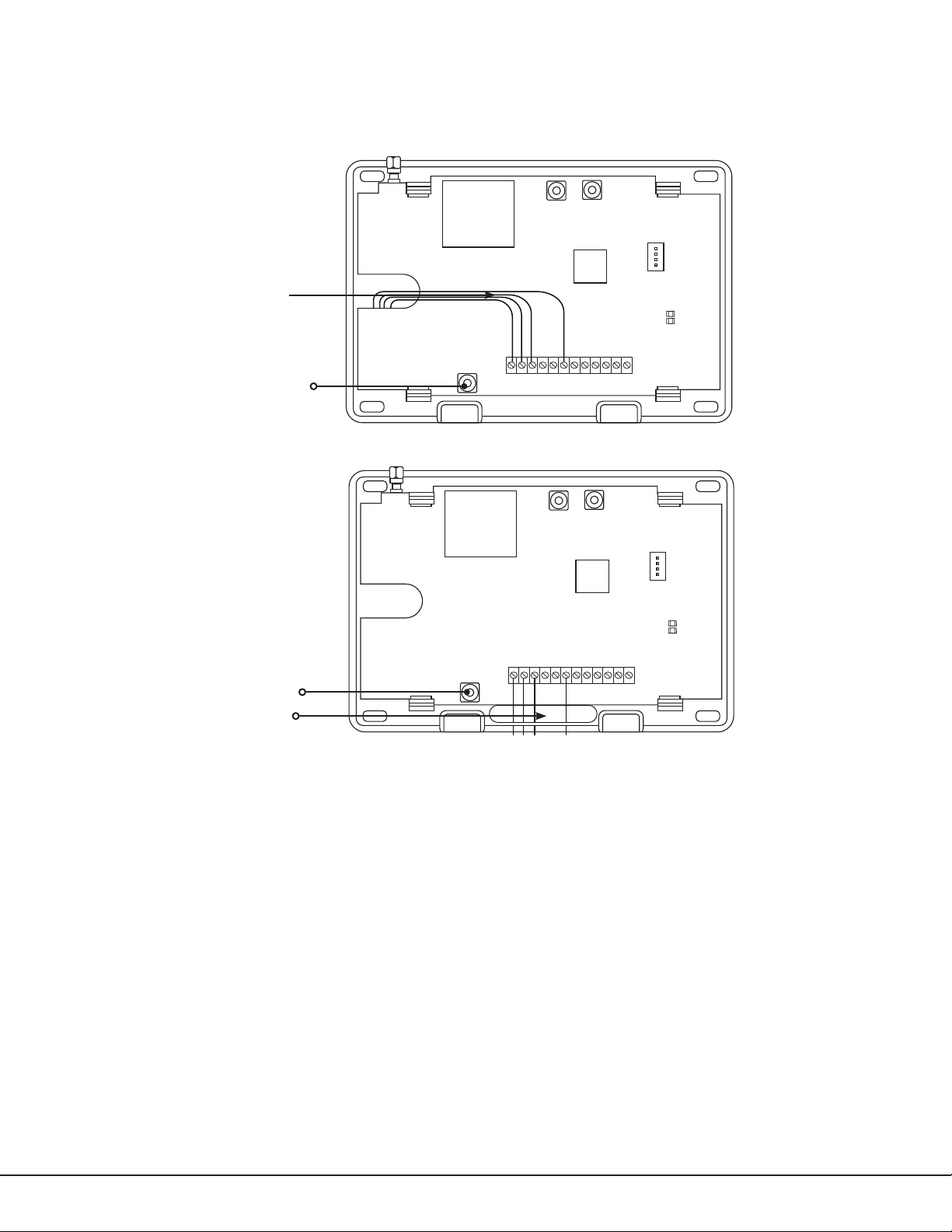
When connecting component wires, route all wires so they will not interfere with the tamper switch. See Figure 2 and
Figure 3 for wire routing options.
RESETLOAD
BR
PROG
+Z4-
Tamper
+DC- Z1 Z2 Z3
G
Figure 2: Wire Routing Option One
T
R
O1 O2
RESETLOAD
BR
PROG
+Z4-
Tamper
+DC- Z1 Z2 Z3
G
O1 O2
T
R
Wiring
Figure 3: Wire Routing Option Two
Connect the Antenna
Place the antenna onto the SMA connector. Refer back to Figure 1. Twist the antenna until it is securely tightened.
Replace the housing cover on the mounted base. Be sure to not damage any PCB components when removing or
replacing the housing cover.
DualCom
Programming and Installation Guide Digital Monitoring Products
5
Page 10
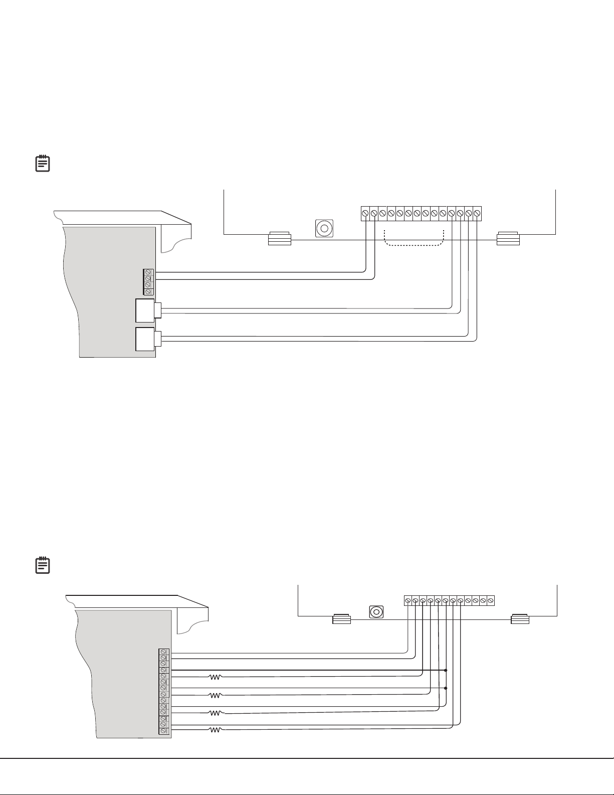
APPLICATIONS
+DC- Z1 Z2 Z3
G
T
R
+Z4-
O1 O2
Use 18-22 AWG for
Power Supply connection
Z3 +
Z4 +
Z4 -
GND
Aux. Output
+
-
Ground
Control Panel
The panel or separate power
supply must be 12/24 Volt
Regulated and Power Limited.
Z1 +
+
–
Z2 +
Normally Open
Common
Normally Closed
Normally Open
Common
Normally Closed
Normally Open
Common
Normally Closed
Normally Open
Common
Normally Closed
1k ohm
1k ohm
1k ohm
1k ohm
Figure 5: Wiring Diagram for Burglary Zones 1‑4
The communicator can be used in a variety of applications.
CID Dialer Connection
Directly connect one or both tip and ring terminals from the control panel to the communicator. See Figure 4. This
connection captures Contact ID messages from any fire panel that are based on the SIA communication standard
DC‑05‑1999.09‑DCS. Messages are then formatted into a Serial 3 message and sent to an SCS‑1R Receiver or SCS‑VR
Receiver.
Note: CID Dialer Connection cannot be used when using Zone 4 Bell Connection. Do not connect telephone
company wires to the communicator. Remove any connected telephone company wires from the control panel.
Use 18-22 AWG
for Power Supply
Control Panel
The panel or separate power
supply must be listed for fire,
regulated, and power limited.
12/24 VDC Aux. Output
Ground
BELL +
BELL -
Telephone
Jack
Connector
Telephone
Jack
Connector
connection
+
-
If FACP only has one phone line, connect to T2, R2
Wiring to FACP shall be connected within 20 ft in the same room and routed in conduit.
+DC- Z1 Z2 Z3 G T1 R1 T2+Z4- R2O1 O2
+
–
No Connection
(Zone Inputs Not
Evaluated By UL)
Tip 2
Ring 2
Ring 1
Tip 1
Figure 4: Wiring Diagram for Tip and Ring Connection
Communication Failure (DualComNF only)
The phone line voltage on the second tip and ring will drop when the DualComNF is in a communication failure state.
This triggers the host panel to annunciate a communication failure. When communication is restored, voltage is
restored on the second tip and ring terminal and the host panel sees a restoral on the phone line.
Zones 1‑4 Input Connection
Connect each control panel relay output to a zone on the communicator. For programming purposes, the zone
numbers are 1‑4. The following are examples of how you might use this application for a burglary or fire alarm.
Burglary
Use a normally closed output on a burglary control panel to indicate a burglary alarm. The communicator zone should
be programmed with a zone name and burglary zone type. When the output on the control panel turns on and trips
the communicator zone, a message is sent to an SCS‑1R or SCS‑VR receiver at the central station. The zone name
programming can be used to describe which control panel zone indicated a burglary. See Figure 5.
Note: Zone4 can only be used as a standard input zone when not programmed as zone type Auxiliary2 (A2). See
Zone4 Bell Connection.
Digital Monitoring Products
6
DualCom
Programming and Installation Guide
Page 11

Zone4 Bell Connection
Table 2: Message Breakdown
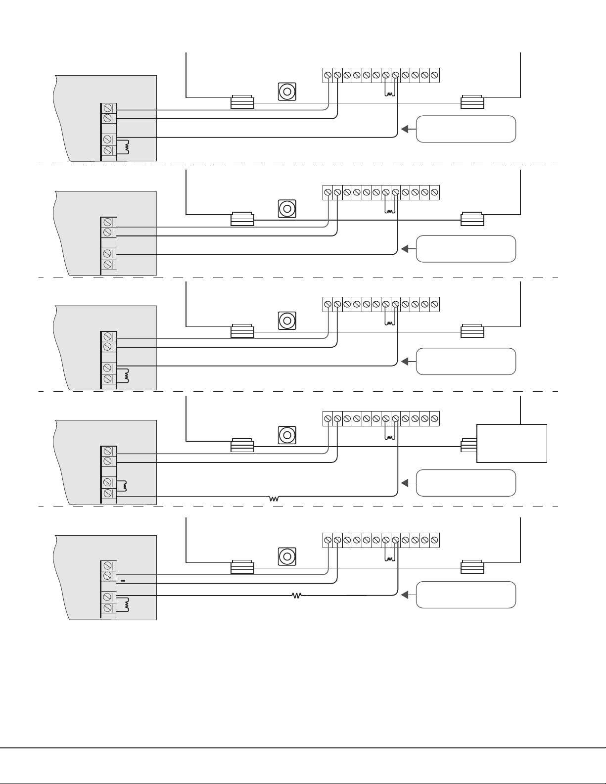
Zone4 (Z4+ and Z4‑) can be connected to the control panel bell output. This zone detects an alarm condition on the
control panel by monitoring the voltage and cadence timing of the bell output. The communicator evaluates the first
3.5seconds of bell cadence timing to detect the type of alarm sent. See Figure 6.
3.5 sec
On
Steady
O
On
Pulse
O
On
Temporal 3
O
On
Temporal 4
O
To enable alarm detection operation, Zone4 Bell Connection must be programmed as Zone Type (A2) in Zone
Information programming. See Table 2 for bell cadence type, zone number, and type of message sent to the receiver.
The communicator generates zones5 and6 using the zone name of zone4 to send to the central station. Zones5
and6 cannot be preprogrammed in Zone Information. CID Dialer Connection cannot be used when using Zone4 Bell
Connection.
1.0 sec 1.0 sec 1.0 sec 1.0 sec 1.0 sec
.5 sec .5 sec .5 sec 1.5 sec .5 sec.5 sec .5 sec .5 sec
Each .1 sec On
5.0 sec
Each .1 sec O
Figure 6: Zone 4 Bell Cadence Information
Each .1 sec On
Each .1 sec O
BELL CADENCE ZONE NUMBER TYPE OF MESSAGE
Steady Zone4 Burglary
Pulse or Temporal3 Zone5 Fire
Temporal4 Zone6 Emergency or Carbon Monoxide
DualCom
Programming and Installation Guide Digital Monitoring Products
7
Page 12
DMP Panel
12 VDC Aux. Output
+
Use 18-22 AWG
for Power Supply
connection
+DC- Z1 Z2 Z3
+
–
+Z4-
G
1k Ω
O1 O2
Z4 -
T
R
-
1k Ω (for Supervision)
ADEMCO Panel
12 VDC Aux. Output
+
-
12 VDC BELL +
BELL -
NAPCO Panel
12VDC Aux. Output
+
-
12 VDC BELL +
BELL -
2.2k
Ω
(for Supervision)
Use 18-22 AWG
for Power Supply
connection
Use 18-22 AWG
for Power Supply
connection
+DC- Z1 Z2 Z3
+
–
+DC- Z1 Z2 Z3
+
–
Voltages above 1.4 VDC
are considered Alarm
+Z4-
G
1k Ω
O1 O2
Z4 -
T
R
Voltages above 1.4 VDC
are considered Alarm
+Z4-
G
1k Ω
O1 O2
Z4 -
T
R
Voltages above 1.4 VDC
are considered Alarm
DSC Panel
12/24 VDC Aux. Output
12/24 VDC BELL +
BELL -
24 VDC Panel
12/24 VDC Aux. Output
24 VDC BELL +
BELL -
Use 18-22 AWG
for Power Supply
connection
+
-
1k
Ω
(for Supervision)
Use 18-22 AWG
for Power Supply
connection
+
-
4.7k Ω (for Supervision if required)
+DC- Z1 Z2 Z3
+
–
10k Ω
+DC- Z1 Z2 Z3
+
–
1k Ω
Figure 7: Zone 4 Bell Connection
+Z4-
G
1k Ω
O1 O2
Z4 -
T
R
Program Zone 4
DO - Alarm
AO - Alarm
Voltages above 0.7 VDC
are considered Alarm
+Z4-
G
1k Ω
O1 O2
Z4 -
T
R
Voltages above 1.4 VDC
are considered Alarm
Digital Monitoring Products
8
DualCom
Programming and Installation Guide
Page 13
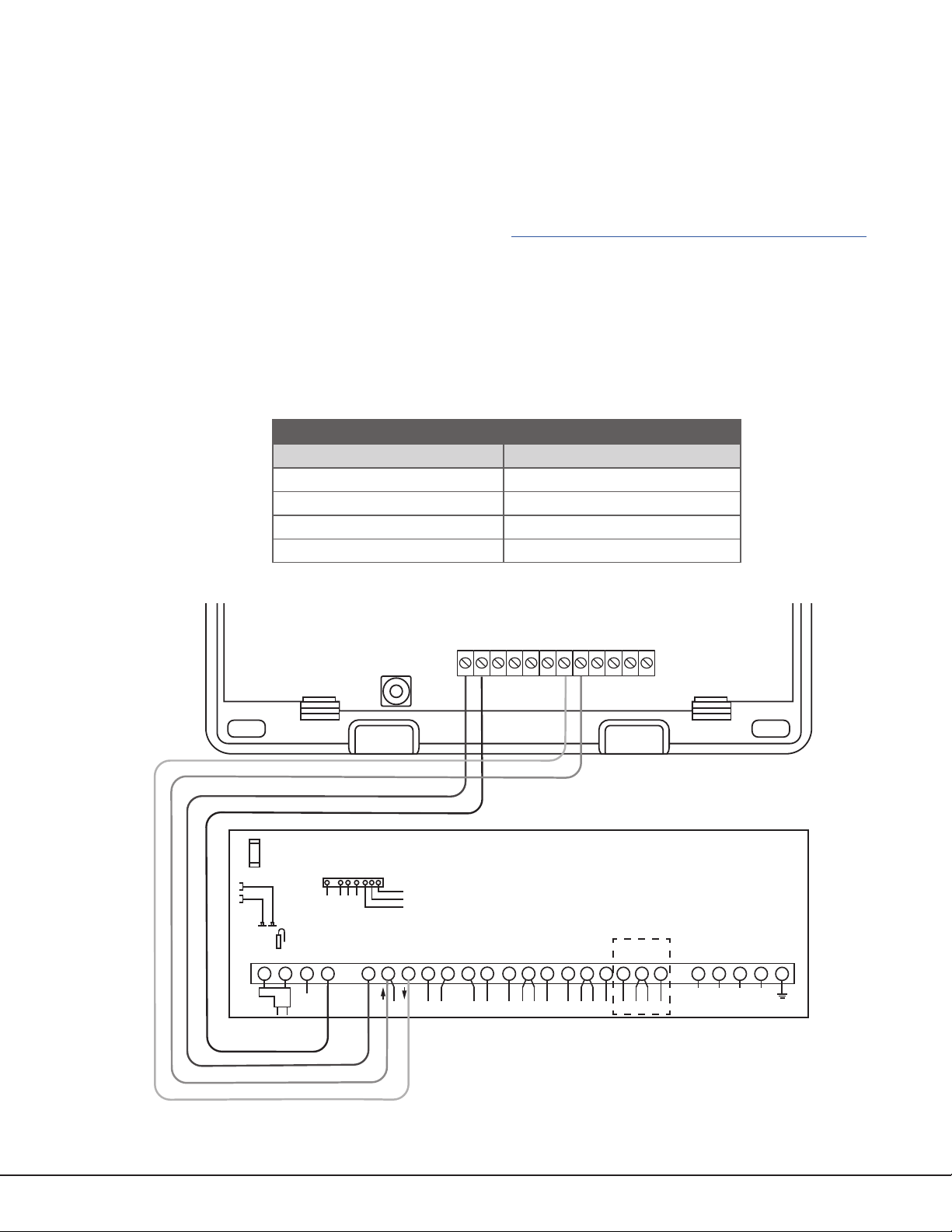
ECP Passthru Connection
PROG
B
R
RESETLOAD
+DC- Z1 Z2 Z3
G
T
R
+Z4-
O1 O2
DualCom
1 2 3 4 5 6 7 8 9 10 11 12 13 14 15 16 17 18 19
20
21 22 23 24
25
+ +–
HI
HI
HI
LO
LO
LO
LO
HI
HI
LO
LO
HI
HI
LO
LO
HI
TIP
(BROWN)
RING
(GRAY)
TIP
(GREEN)
RING
(RED)
+
-
BLACK
RED
SYNC
COM
DATA
(USE SA4120XM-1
CABLE)
1 2 3 4 5 6 7 8
OUT 17
+12 AUX
GND
OUT 18
VISTA 20P ONLY
VISTA-20P
From DC+
From DC–
From Z4+
From Z4-
To Data In (6)
To Data Out (7)
To Negative (4)
To Positive (5)
RED
BLACK
GREEN
YELLOW
RED
BLACK
GREEN
YELLOW
RED
BLACK
GREEN
YELLOW
The communicator can be connected to the ECP Bus of a compatible VISTA panel. Refer to “VISTA Panel
Compatibility” for VISTA compatibility details. See Table 3 and Figure 8 for wiring details.
Configuration
To configure the communicator for ECP Passthru, set KEYPAD INPUT to ECP, program VISTA keypad device
address20, then use the ECP SETUP feature in the Diagnostics (DIAG) menu. For details, refer to “Keypad Input” and
“ECP Setup”.
For more information about configuring ECP Passthru, refer to COM Series How‑To Guide: ECP Passthru (LT‑2209).
Program Vista Keypad Device Address 20
1. Power down and then power up the Honeywell panel.
2. Within 1 minute of powering up the Honeywell panel, simultaneously press and hold the # and * buttons on the
keypad.
3. The keypad displays INSTALLER CODE. Enter the installer code (default is 4112), followed by 800.
4. Enter *193, then enter 1 0.
5. To save and exit programming, enter *99.
COMMUNICATOR TO ECP WIRING
Communicator Terminal VISTA Terminal
+DC Keypad Power
‑DC Keypad GND
Z4+ Data Out
Z4‑ Data In
Table 3: ECP Terminal Connections
DualCom
Programming and Installation Guide Digital Monitoring Products
Figure 8: ECP Passthru Wiring
9
Page 14
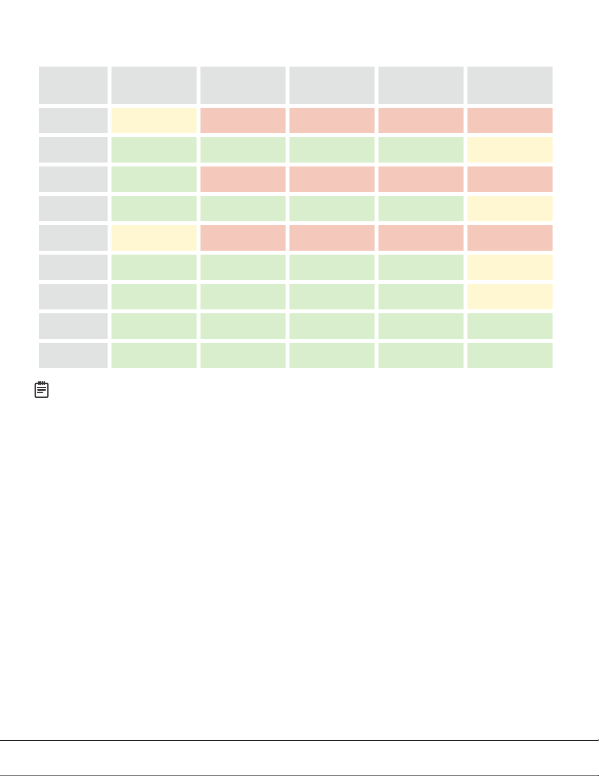
VISTA Panel Compatibility
Remote
Arming/
Disarming
Remote
Zone Status
Compatible with
Compass
Panel Type ECP
Remote
User Management
VISTA‑10SE Rev 15 or higher No No No No
VISTA‑10P Yes Ye s Yes Yes
Firmware version
2.0 or higher
VISTA‑15 Yes No No No No
VISTA‑15P Yes Yes Ye s Yes
Firmware version
5.2 or higher
VISTA‑20SE Rev 12 or higher No No No No
VISTA‑20P Yes Yes Ye s Yes
VISTA‑20PI Ye s Yes Ye s Yes
Firmware version
5.2 or higer
Firmware version
5.0 or higher
VISTA‑21iP Ye s Yes Ye s Yes Yes
VISTA‑21iPLTE Yes Ye s Yes Ye s Yes
Note: Panels must be programed in the Stay/Away mode for Remote Arming/Disarming (No Partitions).
Vista 32, 40, 50, 128, 250 are not compatable with ECP Virtual Keypad.
Digital Monitoring Products
10
DualCom
Programming and Installation Guide
Page 15
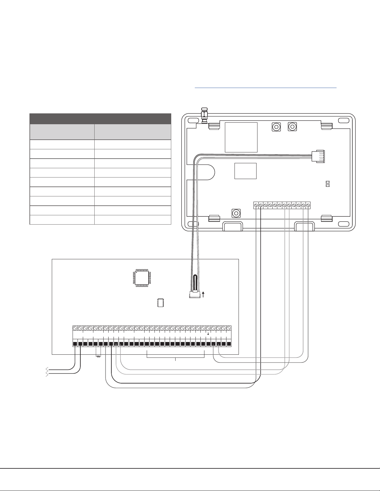
DSC Passthru Connection
RESETLOAD
+DC- Z1
Z2 Z3
G
T
R
+Z4-
O1 O2
+DC- Z1
Z2 Z3
G
T
R
+Z4-
O1 O2
DualCom
ETHERNET
DSC PC1864
AC AC +AUX- +BELL- RED BLKYEL GRN 1 PGM 2 3 PGM 4 Z1 COM Z2 Z3 Z4 Z5 Z6 Z7 Z8
EGND RING TIP
R-1 T-1COM COM COM
AC +AUX-
+BELL- REDBLK YEL GRN 1 PGM 2 3 PGM 4 Z1 COM Z2 Z3 Z4 Z5 Z6 Z7 Z8
EGND
A
RINGBTIPCR-1DT-1
COM COM COM
1k Ω
EOL
5.6k Ω EOL
To AC
Power
From DC +
From DC -
From Z4 +
From Z4 -
From T
To RED
To BLK
To YEL
To TIP
To RING
To GRN
From R
Remote
Programming
Connection
(Model 330-DSC)
RED
BLACK
BLACK
BLACK
YELLOW
GREEN
GREEN
RED
PROG
PC LINK
1
CON 4
YELLOW
GREEN
YELLOW
GREEN
TAB
UP
BR
The communicator can be connected to the DSC Bus of a DSC PowerSeries Model PC1616, PC1832, or PC1864. Refer
to Table 4 and Figure 9 for wiring details.
Configuration
To configure the communicator for DSC Passthru, set KEYPAD INPUT to DSC and use the DSC SETUP feature in the
Diagnostics (DIAG) menu. For details, refer to “Keypad Input” and “DSC Setup”.
For more about configuring DSC Passthru systems, refer to COM Series How‑To Guide: DSC Passthru (LT‑2208).
COMMUNICATOR TO DSC WIRING
Communicator
Terminal
DC+ RED
DC‑ BLK
Z4+ YEL
Z4‑ GRN
T or T1 TIP
R or R1 RING
N/A Bell+ to Bell‑ (1k Ω EOL)
N/A Zones 1 ‑ 8 (5.6k Ω EOL)
PROG PC Link (COM) Tab Up
Table 4: DSC Terminal Connections
DSC Terminal
Figure 9: DSC Passthru Wiring
DualCom
Programming and Installation Guide Digital Monitoring Products
11
Page 16
ARMING AND DISARMING
+DC- Z1
Z2 Z3
G
T
R
+Z4-
O1 O2
+
–
Use 18-22 AWG
for Power Supply
connection
O2
12 VDC Aux. Output
+
-
GND
Zone 1
Zone 2
Control Panel EOL resistor
Use the Virtual Keypad App
Using a smartphone with the DMP Virtual Keypad App or a computer with VirtualKeypad.com, you can connect to the
communicator to arm areas, turn outputs on and off, and add, edit, or remove users. See Figure 10.
Figure 10: Virtual Keypad Applications
Use Outputs
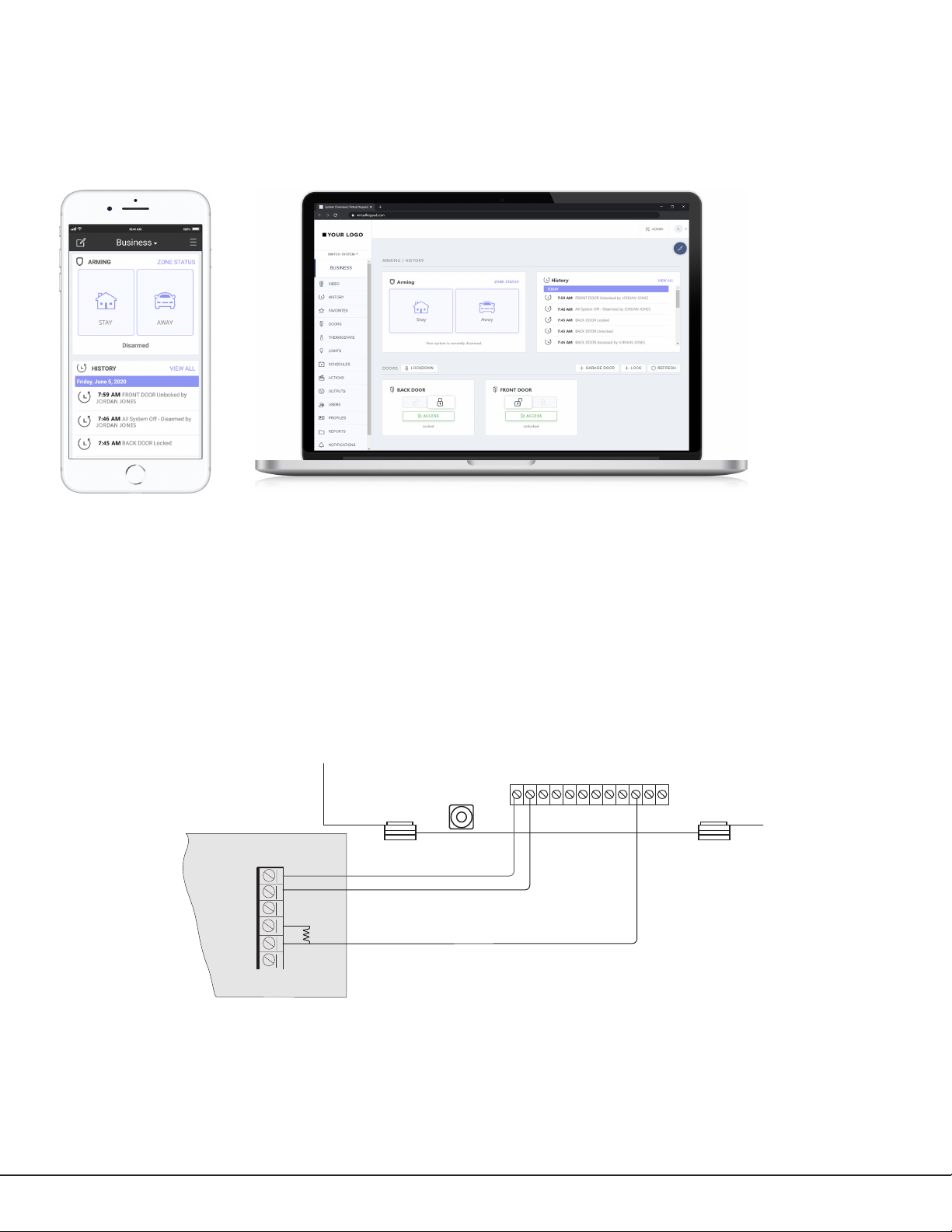
A burglary control panel zone may be programmed as an arming zone and connected to output O1 or O2. See
Figure 11. Program the output number in armed output or remote arming output in output options when programming
the communicator. See Armed Output or Remote Arming Output. The communicator output connections can be used
with any of the applications listed in this guide. See Applications.
Communicator to Panel Burglary Zones
1. Connect the communicator’s Z1 (zone 1) terminal to the control panel’s armed output terminal.
2. Connect the communicator’s O1 (output 1) terminal to the control panel’s keyswitch or arming zone.
Digital Monitoring Products
12
Figure 11: Communicator to Burglary Control Panel Zones
DualCom
Programming and Installation Guide
Page 17
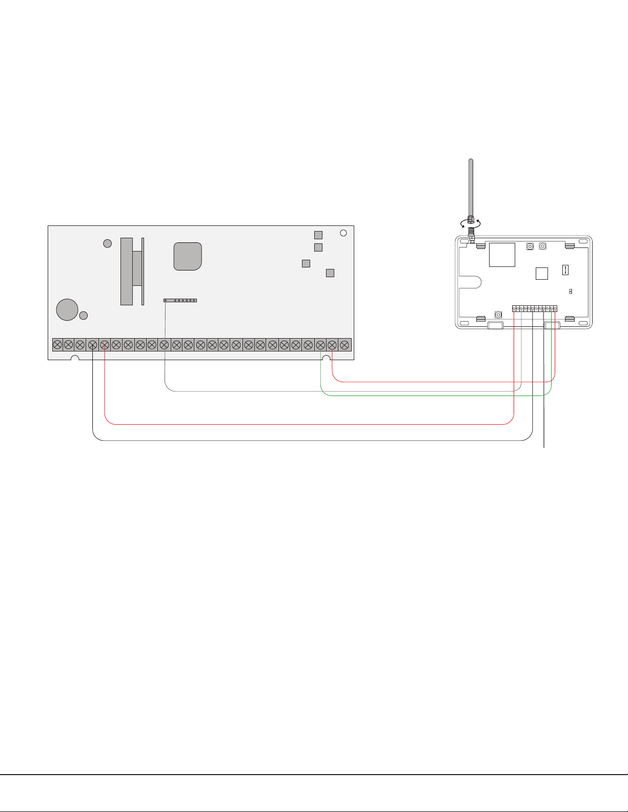
Honeywell Vista 20 Panel Wiring
1. Connect the communicator’s Z1 (zone 1) terminal to output 17 on the control panel.
2. Connect the communicator’s O1 (output 1) terminal to the control panel’s keyswitch or arming zone.
3. Connect the T (tip) terminal on the communicator to terminal 23 on the control panel.
4. Connect the R (ring) terminal on the communicator to terminal 24 on the control panel.
5. Power the communicator by connecting its terminal +12V to terminal 5 on the control panel.
6. Connect the communicator’s GND (ground) terminal to terminal 4 on the control panel.
RESETLOAD
BR
PROG
OUTPUT 17
1 2 3 4 5 6 7 8 9 10 11 12 13 14
Honeywell Vista 20 Series
16 17 18 19
15
21 22 23 24
20
25
Figure 12: Vista 20 Series Control Panel to DualCom
DualCom
+Z4-
+DC- Z1
keyswitch or arming
T
Z2 Z3
R
O1O2
G
Connect to any
zone.
DualCom
Programming and Installation Guide Digital Monitoring Products
13
Page 18

ACTIVATE THE CELLULAR MODULE
For more information about using Dealer Admin, Tech APP, or Remote Link, refer to DMP.com/dmphelp.
Dealer Admin Activation
1. Find the customer and select their name.
2. The customer’s summary page opens. In the Systems section, press the Add icon.
3. Enter the system name.
4. In System Type, select DualCom.
5. In Connection Type, select Cellular or EASYconnect + Cell Backup.
6. In SIM Number, enter the SIM number and press Get Status.
7. Press Activate.
8. In Account Number, enter the system’s receiver number followed by the account number.
9. Select a Rate Plan for the communicator.
10. Enter the panel Serial Number.
11. Enter the panel Remote Key. The remote key must match the one programmed in panel REMOTE OPTIONS.
12. To confirm proper communication, press Test Connection.
13. A dialog pops up to ask if you want to perform the initial connection to the panel. Press Yes .
14. Configure additional options as needed, then press Save.
Tech APP Activation
1. Go to the Customer Summary > Systems.
2. Tap the Add icon.
3. Enter the System Name.
4. Enter the panel Serial Number.
5. In System Type, select DualCom.
6. In Connection Type, choose Cellular or EASYconnect + Cell Backup.
7. In Account Number, enter the system’s receiver number followed by the account number.
8. Enter the panel Remote Key. The remote key must match the one programmed in panel REMOTE OPTIONS.
9. Enter the SIM Number and tap Get MEID/SIM Status.
10. Select a Rate Plan for the communicator.
11. Configure additional options as needed, then tap Save.
Remote Link Activation
1. Go to File > Panel Information.
2. Press New.
3. In Model, select DualCom.
4. If necessary, enter a firmware version number in Version.
5. Enter the receiver number and account number, then press OK.
6. In Connection Information, select Cellular.
7. Enter the panel Remote Key.
8. Enter the cellular Phone Number.
9. Press OK.
10. Go to Program > Communications.
11. In Connection, press Activate.
12. Select SIM as the SIM Type.
13. Enter the SIM number, then select a Rate Plan.
14. Press Activate.
Digital Monitoring Products
14
DualCom
Programming and Installation Guide
Page 19
PROGRAMMING
Before You Begin
Read this guide before you begin programming. This guide allows you to quickly learn the programming options and
operational capabilities of the DualCom. The communicator contains all of its programming information in an on‑
board processor and does not require an external programmer.
In addition to this manual, you should also be familiar with the following document:
• DualCom Communicator Programming Sheet (LT‑1860)
Programming Sheet
Fill out the programming sheet included with this device before you begin programming. The programming sheet lists
the various options available for programming the communicator and allows you to keep a record of what options you
intend to enter, reducing programming errors.
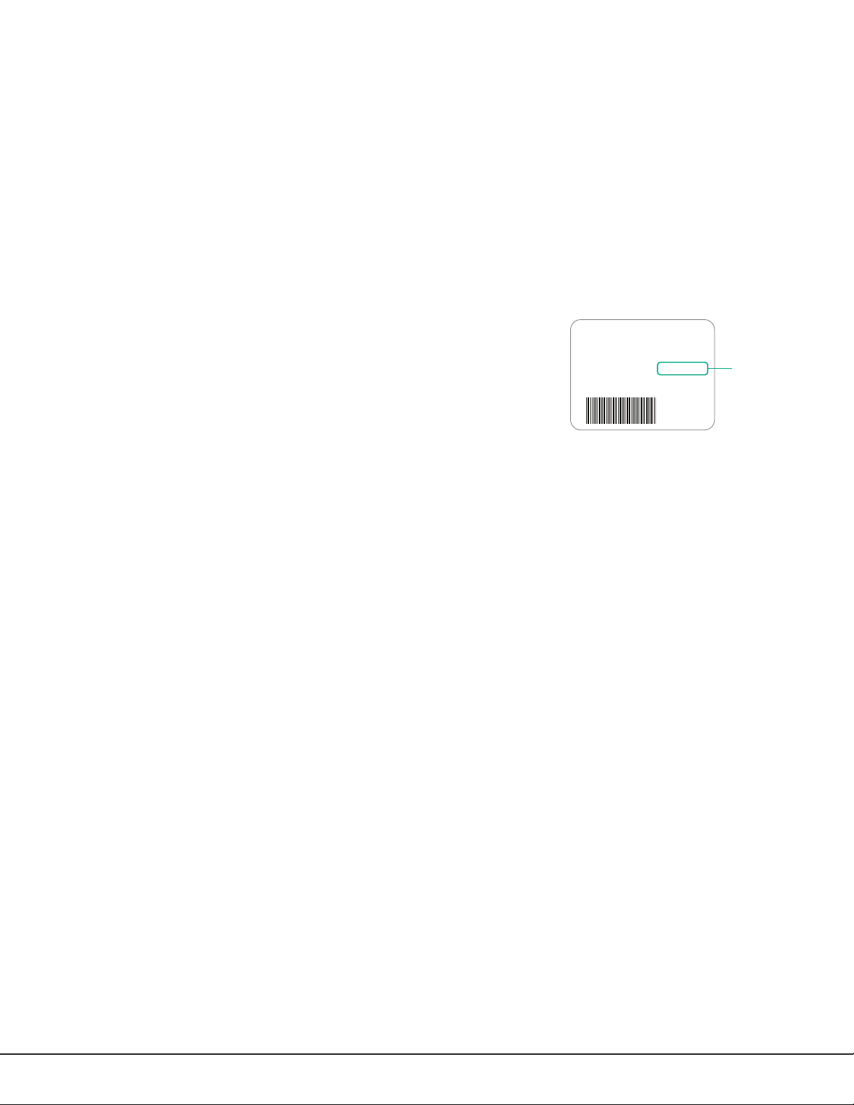
Default Master Code
Universal Communicators Version 194 and higher ship with a unique four‑digit
default master code. This master code is generated with an algorithm that
ensures it cannot be duplicated. The code can be modified or deleted in panel
programming. To revert the default code to99, use the Clear All Codes option
found in the Initialization menu. Panels ship with the master code on the serial
number label next to the serial number.
Getting Started
Initializing the Communicator
When programming a communicator for the first time or rewriting the entire program of an existing communicator,
use the initialization programming option. See Initialization. Initializing clears the communicator’s memory and sets
the highest user number to user code 99.
MAC : 00:01:22:33:44:55
MOD : DUALCOM
VER : 194 122319
SN : 0012345A CODE21852
TD : 011520
KEY : 100
Default
User Code
Accessing the Programmer
To access the programmer function of the
1. Connect the keypad to the programming header.
2. Press and release the reset button.
3. Enter 6653 (PROG). The keypad displays PROGRAMMER.
communicator
:
Programming Menu
The following is a list of programming menu options available in the programming menu. Press CMD to advance
through the programming menu options. To select a menu option, press any select area when the desired menu
option displays on the keypad. Use this list to navigate to your desired programming menu option in this guide.
• Initialization
• Communication
• Network Options
• Remote Options
• System Reports
• System Options
• Output Options
• Area Information
• Zone Information
• Stop
• Set Lockout Code
• Z‑Wave Setup (DualComWZ only)
DualCom
Programming and Installation Guide Digital Monitoring Products
15
Page 20
Reset Timeout
CMD
You must enter the programmer menu within 30minutes of resetting the communicator to avoid reset timeout. After
30minutes, if you attempt to program by entering the 6653 (PROG) code, the keypad displays RESET PANEL. You
must reset the communicator and enter the program code within the next 30minutes.
If you are already in the programmer menu and do not press any keys on the keypad for 30minutes, the
communicator
To exit the programmer menu, use the stop option. The stop option is the second‑to‑last option in programming and
disarms all areas. The programming session is terminated and the keypad returns to status list or main screen.
exits programming. All data entered up to that point is saved in the communicator memory.
Special Keys
The following keys and areas are common to all DMP LCD and graphic touchscreen keypads.
Command
Press CMD to advance through the programmer menu and through each step of a programming section.
As you advance through the programmer menu, the keypad display any current programming already
stored in the communicator memory. If no change is required for an option, press CMD to advance to the
next step.
CMD is also used to enter information into the communicator’s memory such as an IP address or a zone
name. Press CMD after entering information.
Back Arrow
Use the back arrow to back up one step in a programming menu or to erase a typing error while entering
information.
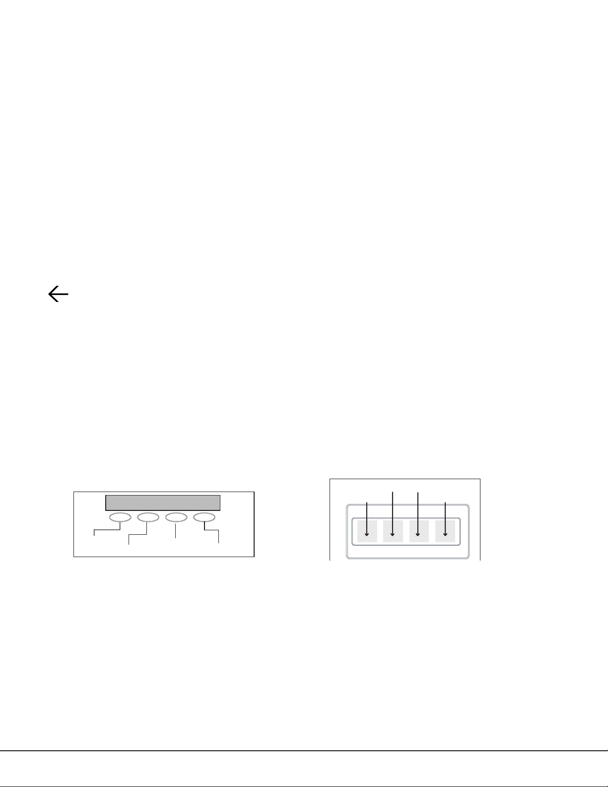
Select Areas
The top row of keys on LCD Keypads are called select areas. The select areas on graphic touchscreen keypads are
along the top of the keypad. When you need to press a select area, the keypad displays the options.
When there are more than four re sponse options avail able, press CMD to display the next set of options. Press the
back arrow to return to the previous options.
LCD Keypads
The first select area is on the far left. The second select area is second from the left. The third select area is second
from the right. The fourth select area is on the far right and is for special characters. See Figure 13.
Graphic Touchscreen Keypads
When instructed to press the first select area, touch select area 1; the second select area, touch select area2; third
select area, touch select area3; and the fourth select area, touch select area 4. See Figure 14.
Select Area 2
(CBA
First Letter
Second Letter
Figure 13: LCD Keypad Select Keys Figure 14: Graphic Touchscreen Keypad Select Areas
Third Letter
Special Character
Select Area 1
32-Character Display
Select Area 3
Select Area 4
Digital Monitoring Products
16
DualCom
Programming and Installation Guide
Page 21
Letters and Special Characters
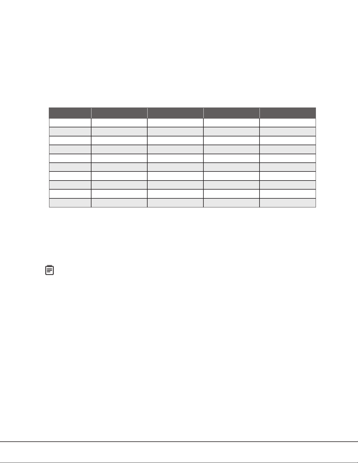
Use the number pad directions below to enter letters and special characters on a number pad or use the standard
keyboard directions to enter letters and special characters on a standard keyboard.
Number Pad
1. Choose a character from Table 5.
2. Identify the number the character correlates with and press that number on the number pad.
3. Identify the select area for that character and press that select area on the keypad. To access the lowercase
letter, press that select area again.
4. When the desired character displays on the keypad, return to step1 to enter another character or press CMD if
finished.
NUMBER SELECT KEY 1 SELECT KEY 2 SELECT KEY 3 SELECT KEY 4
1 A B C (
2 D E F )
3 G H I !
4 J K L ?
5 M N O /
6 P Q R &
7 S T U @
8 V W X ,
9 Y Z space _
0 ‑ . * #
Table 5: Entering Letters and Special Characters in the Number Pad
Standard Keyboard
• Press ABC to access uppercase letters.
• Press abc to access lowercase letters.
• Press !@# to access symbols and special characters.
• Press 123 to access the number pad.
Note: Not all keypad prompts accept letters and/or symbols. For example, pressing P on the ENTER CODE
prompt could display a 6 on the keypad.
Current Programming
Each programming option that displays shows the information already programmed in the communicator memory. To
change the already programmed information, simply replace the information. To change a programming option that
requires a YES or NO response, press the select area for the desired response.
DualCom
Programming and Installation Guide Digital Monitoring Products
17
Page 22
INITIALIZATION
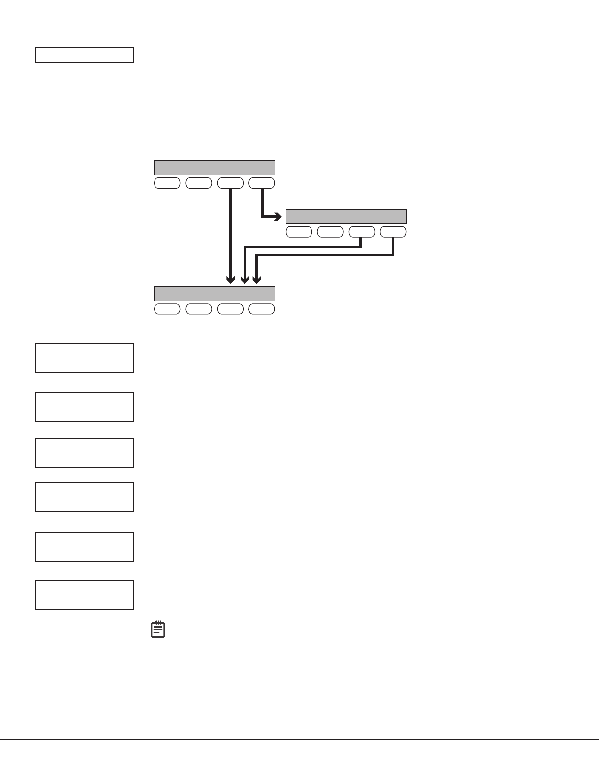
If you choose YES, the panel initializes that section
INITIALIZATION
This option allows you to set the communicator’s programmed memory back to the factory
defaults in preparation for system programming.
After selecting YES to clear a section of memory, the communicator asks if you are sure
you want to clear the memory. This is a safeguard against accidently erasing part of your
programming. No memory is cleared from the programming until you answer YES to the
confirmation prompt. See Figure 15.
Use YES/NO options to initialize
programmable parts of the panel.
CODES? NO YES
SURE? YES NO
SCHEDS? NO YES
SURE? YES NO
EVENTS? NO YES
SURE? YES NO
CODES?
NO YES
Choose YES to advance to
a confirmation prompt.
SURE? YES NO
Choose NO to
advance to the
next option.
SCHEDS? NO YES
Figure 15: Alternating Yes and No Options
of the program and advances to the next prompt.
If you choose NO, the panel advances to the next
option and does not initialize that section of the
program.
CLEAR ALL CODES
Choose NO to leave existing codes intact.
Choose YES to clear the user code memory and assign user code number 99 to user20.
CLEAR ALL SCHEDULES
Choose NO to leaves existing schedules intact.
Choose YES to clears all schedules from the programming.
CLEAR EVENTS
Choose NO to leave existing event memory intact.
Choose YES to clear all event memory in the display events buffer.
ZONES? NO YES
SURE? YES NO
COMMS? NO YES
SURE? YES NO
DEFAULTS? NO YES
SURE? YES NO
Digital Monitoring Products
18
CLEAR ZONE PROGRAMMING
Choose NO to leave existing zone information intact.
Choose YES to set all zones in the system to *UNUSED*.
CLEAR COMMUNICATION
Choose NO to leave existing communication programming intact.
Choose YES to clear communication to factory defaults.
SET TO FACTORY DEFAULTS
Choose NO to leave the remainder of the existing communicator programming intact.
Choose YES to set the communicator programming back to factory default selections.
Note: Choosing YES does not clear the event memory, zone, user code information, or
schedules.
DualCom
Programming and Installation Guide
Page 23
COMMUNICATION
COMMUNICATION
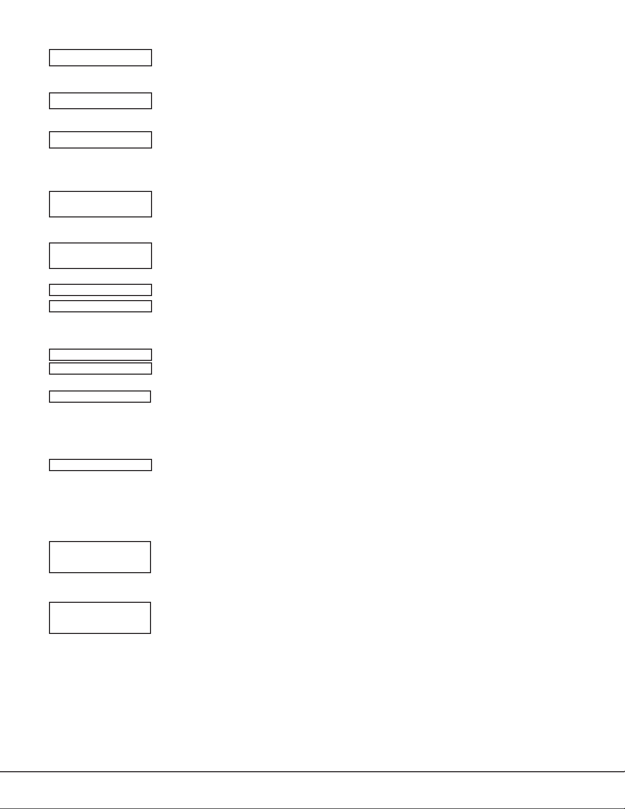
This option allows you to configure the communication settings for the communicator.
ACCOUNT NO:
XMIT DELAY: 0
COMM TYPE:
NET WIFI CELL
BACKUP CELL?:
NO YES
TEST TIME
00:00 AM
NET TST DAYS: 1
CELL TST DAYS: 1
ACCOUNT NUMBER
Enter the account num ber sent to the receiver. The range is 1‑65535. For account numbers
of four digits or less, do not enter leading zeros.
TRANSMISSION DELAY
Enter the number of seconds the communicator waits before sending burglary alarm
reports to the receiver. The range is 15‑45seconds. The default is 0. Enter 0 to disable this
function.
COMMUNICATION TYPE
The communicator uses NET or WI‑FI and CELL to connect with SCS‑1R or SCS‑VR
receivers. DualComNF models use NET and CELL and default to NET. DualComWZ models
use WI‑FI and CELL and default to WI‑FI.
BACKUP CELL
If NET or WI‑FI is selected as the primary communication type, BACKUP CELL will display
and give you the option to enable or disable cellular backup.
TEST TIME
Enter the time of day the communicator should send the test report to the SCS‑1R or
SCS‑VR receivers. Use entries between 12:00 to 11:59 and then choose AM or PM. To enable
daily tests from the host panel, leave the time blank and enable test reports for receiver1
and/or for receiver2. See Test Report.
NET/CELL TEST DAYS
If you entered a test time, you can enter how often the panel test report is sent to the
receiver. The range is 1 to 60 and the default is 1. Enter 0 to disable the test report.
CHECKIN: 0
FAIL TIME: 0
BACKUP
CHECKIN: 0
BACKUP
FAIL TIME: 0
CHECK‑IN MINUTES
Check‑in reports are a method of supervising the panel for communication with
the receiver. Enter the number of minutes between check‑in reports. The range is
3‑240minutes. The default is 0. Enter 0 to disable check‑in minutes.
Note: Additional cell charges may apply if this option is used.
FAIL TIME MINUTES
Fail time allows the SCS‑1R or SCS‑VR receivers to miss a defined number of check‑ins
before logging that the panel is missing. For example, if cell check‑in is 20minutes and fail
time is 30minutes, the receiver only indicates a Panel Not Responding after 30minutes.
The fail time must be equal to or greater than the cell check‑in minutes. If cell check‑in
is 20minutes, the fail time must be 20minutes or more. The range is 3‑240minutes. The
default is 0.
BACKUP CHECK‑IN MINUTES
Set the number of minutes between check‑in reports for BACKUP CELL if it was enabled.
The range is 3‑240minutes. The default is 0. Enter 0 to disable check‑in minutes.
Note: Additional cell charges may apply if this option is used.
BACKUP FAIL TIME MINUTES
Set the number of minutes the receiver should wait to indicate that a panel is missing
using BACKUP CELL if it was enabled. If cell check‑in is 20minutes, the fail time must be
20minutes or more. The range is 3‑240minutes. The default is 0.
DualCom
Programming and Installation Guide Digital Monitoring Products
19
Page 24
RECEIVER 1 PROG
RECEIVER1 PROGRAMMING
This option allows you to set the options for the first receiver the communicator attempts
to contact when sending reports from the host panel and/or communicator. The
communicator supports communication up to two receivers.
ALARM NO YES
SPV/TRBL NO YES
O/C USER NO YES
TEST RPT NO YES
FIRST IP ADDR
000.000.000.000
FIRST IP PORT
2001
Alarm Reports
Choose YES to enable Abort, Alarm, Alarm Restoral, Alarm Bell Silenced, Ambush, Exit
Error, and System Recently Armed reports to be sent to this receiver. The default is YES.
Choose NO to disable sending these reports to the receiver.
Supervisory/Trouble Reports
Choose YES to enable Supervisory, Trouble, Trouble Restoral, Force Armed, and Fault
reports to be sent to this receiver. The default is YES.
Choose NO to disable sending these reports to the receiver.
Opening/Closing and User Reports
Choose YES to enable Opening/Closing, Schedule and Code Changes, and Bypass reports
by user to be sent to this receiver. The default is YES.
Choose NO to disable sending these reports to the receiver.
Test Report
Choose NO to disable sending these reports to the receiver.
First IP Address
Enter the first (primary) IP address where the communicator sends messages. Enter
all 12digits and leave out the periods. For example, enter IP address 192.168.0.250 as
192168000250. The periods display automatically.
First IP Port
Enter the first IP port number to be used with the first IP address. The IP port identifies the
port used to communicate messages with the communicator. The default IP port setting is
2001.
SECOND IP ADDR
000.000.000.000
SECOND IP PORT
2001
Second IP Address
Enter the second IP address where the communicator sends messages. Enter all 12digits
and leave out the periods. The periods display automatically.
Second IP Port
Enter the second IP port number to be used with the second IP address. The IP port
identifies the port used to communicate messages to and from the communicator. The
default IP Port setting is 2001.
Digital Monitoring Products
20
DualCom
Programming and Installation Guide
Page 25
RECEIVER 2 PROG
RECEIVER2 PROGRAMMING
Set the options for the second receiver that the communicator attempts to contact
when sending reports from the host panel or communicator. The communicator supports
communication with up to two receivers.
Note: If you select YES for any of the receiver2 options, you must have at least one IP
address programmed in receiver2 programming. The receiver2 defaults are set to NO.
ALARM NO YES
SPV/TRBL NO YES
O/C USER NO YES
TEST RPT NO YES
FIRST IP ADDR
000.000.000.000
FIRST IP PORT
2001
Alarm Reports
Choose YES to enable Abort, Alarm, Alarm Restoral, Alarm Bell Silenced, Ambush, Exit
Error, and System Recently Armed reports to be sent to this receiver.
Choose NO to disable sending these reports to the receiver. The default is NO.
Supervisory/Trouble Reports
Choose YES to enable Supervisory, Trouble, Trouble Restoral, Force Armed, Late to Close,
and Fault reports to be sent to this receiver.
Choose NO to disable sending these reports to the receiver. The default is NO.
Opening/Closing and User Reports
Choose YES to enable Opening/Closing, Schedule and Code Changes, and Bypass reports
by user to be sent to this receiver.
Choose NO to disable sending these reports to the receiver. The default is NO.
Test Report
Choose YES to enable the recall test report from the host panel and/or communicator to
be sent to the receiver.
Choose NO to disable sending this report to the receiver. The default is NO.
First IP Address
Enter the first (primary) IP address where the communicator sends messages. Enter
all 12digits and leave out the periods. For example, enter IP address 192.168.0.250 as
192168000250. The periods display automatically.
First IP Port
Enter the first IP port number to be used with the first IP address. The IP port identifies the
port used to communicate messages with the panel. The default IP port setting is 2001.
SECOND IP ADDR
000.000.000.000
SECOND IP PORT
2001
Second IP Address
Enter the second IP address where the communicator sends messages. Enter all 12digits
and leave out the periods. The periods display automatically.
Second IP Port
Enter the second IP port number to be used with the second IP address. The IP port
identifies the port used to communicate messages with the panel. The default port is 2001.
DualCom
Programming and Installation Guide Digital Monitoring Products
21
Page 26
NETWORK OPTIONS
NETWORK OPTIONS
Network options are provided to define the network configuration for the communicator.
This information will be used during communication of messages via network.
Note: IP addresses and port numbers may need to be assigned by the network
administrator. When entering an IP, gateway, or subnet mask address, be sure to enter
all 12digits and leave out the periods. For example, IP address 192.168.000.250 is
entered as 192168000250.
WPS LIST MANUAL
TEST
SEARCHING .
WPS LIST MANUAL
SEARCHING
SIGNAL
▐▐▐▐▐▐▐
COMNET123
W/L SECURITY:
WPA‑PSK
W/L SECURITY:
WEP WPA NONE
W/L KEY:
*****************
W/L KEY:
‑
WI‑FI SETUP
This option is for connecting to the desired Wi‑Fi network and will display only when
Communication Type is set to Wi‑Fi. Press any select key or area to select.
WPS LIST MANUAL displays. Press the first select key or area to choose WPS to
automatically connect to a WPS enabled router. Press the second select key or area to
choose LIST and see the name and signal strength of any Wi‑Fi routers in range. Press
the third or fourth select key or area to choose MANUAL and enter the name of the Wi‑Fi
router you wish to connect to. Pressing CMD displays TEST. To select TEST, press the first
select key or area to verify connection of your system to the Wi‑Fi network.
WPS
When WPS is selected, SEARCHING displays. Press the WPS button on the Wi‑Fi network
router to which you are attempting to connect. SEARCHING displays for up to two minutes
or until connected to the WPS enabled router. Refer to the router’s instruction manual for
sending a security key to the communicator.
If the panel fails to connect to the WPS enabled router, WPS FAILED RETRY? NO YES
displays. Press the fourth select key or area to RETRY or press the third select key or area
to display WPS LIST MANUAL.
LIST
When LIST is selected, SEARCHING displays until any Wi‑Fi networks are found in range.
Once available Wi‑Fi networks are found the keypad displays the name of the SSID (Wi‑Fi
Network name) and signal strength of each network. Press CMD to scroll through the list
of available Wi‑Fi networks. When the desired network is displayed, press any select key or
area to connect.
Note: If the panel is unable to detect the security type, W/L SECURITY with the default
security type WPA‑PSK displays. If a different security type is required, press CMD and
WEP WPA NONE displays. Press the select key or area of the desired security type to
choose.
When connecting to the Wi‑Fi network the panel also detects the security type in use and
W/L KEY: *************** displays.
Enter the W/L KEY and the panel performs a connection test and CONNECTING displays.
When successful, CONNECTED displays on the keypad. If the panel does not connect to
the Wi‑Fi network, NOT CONNECTED displays. Press CMD to return to the Wi‑Fi setup
main screen.
WPS LIST MANUAL
WIFI SETUP
ENTER SSID
SSID:
SSID FOUND
SSID:
SSID NOT FOUND
Digital Monitoring Products
22
MANUAL
This option allows you to enter the desired network name using the keypad. When
MANUAL is selected, the current settings display. Press CMD to continue with no change.
SecureCom is the default.
Use the number keys on the keypad to enter a new or different SSID (Wi‑Fi Network
name), there is no need to press the select keys or areas. Once the SSID is entered, press
CMD and SEARCHING displays.
When an SSID is entered for the first time or changed, the panel searches for the SSID
entered to ensure communication. The keypad displays SSID FOUND or SSID NOT FOUND.
When the SSID is found, the security type is also detected. Depending on the security
type, the SSID might take several seconds to process.
Enter up to 32 characters for the SSID from the network router to identify the network
LAN. The SSID is blank by default.
While searching, the keypad displays SEARCHING. If the communicator is unable to
connect to the desired network and SSID NOT FOUND displays, press CMD to return to
the main menu and WPS LIST MANUAL displays. Press CMD again to display TEST.
Enter the Wireless Network Key for the network and press CMD to save the key.
DualCom
Programming and Installation Guide
Page 27
TEST
TEST
Press the first select key or area to select TEST and the communicator will attempt to
verify connection of your system to the desired Wi‑Fi network.
W/L SECURITY:
WPA‑PSK
W/L SECURITY:
WEP WPA NONE
W/L KEY:
*****************
W/L KEY:
‑
DHCP NO YES
LOCAL IP ADDR
192.168.0.250
GATEWAY ADDR
192.168.0.1
WIRELESS SECURITY TYPE
When successful, W/L SECURITY displays. Select the security type based on the network
router programming. The default network security type is WPA‑PSK. Press any select key
or area to display the other security options. The available options are WEP, WPA, and
NONE.
Press the first select key or area to choose WEP, press the second select key or area for
WPA , press the third select key or area for NONE.
WIRELESS NETWORK KEY
This option displays only if the communication type is set to Wi‑Fi and Security option
is enabled. Enter the key provided from the network router’s programming. WEP
requires a network password of 10 characters (WEP64) or 26 characters (WEP128),
using a combination of the number 0‑9 and the letters A‑F (See the chart above to enter
lowercase or special characters).
WPA/WPA‑PSK uses a custom key that allows 8 to 32 characters.
Note: Depending on the security type, the key might take several seconds to process.
DHCP MODE ENABLED
Choose YES if the communicator uses a dynamic IP address. The communicator will
operate in DHCP and will not use the local IP address number. The default is YES.
Choose NO to have the communicator use the IP address entered in local IP address.
LOCAL IP ADDRESS
Enter the local IP address for the communicator. The local IP address must be unique and
cannot be duplicated on the network. The default local IP address is 192.168.0.250.
GATEWAY ADDRESS
Enter the local gateway address. The gateway IP address is needed to exit the local
network. The default gateway address is 192.168.0.1.
SUBNET MASK
255.255.255.0
DNS SERVER
0.0.0.0
PROGRAMMING
PORT 2001
SUBNET MASK
Enter the local subnet mask assigned to the communicator. The default subnet mask
address is 255.255.255.000.
DNS SERVER
Enter the IP address of the DNS (Domain Name System) used by the communicator to
resolve domain names into IP addresses. The default address is 0.0.0.0.
PROGRAMMING PORT
Enter the programming port number. The programming port identifies the port used to
communicate messages to and from the communicator. The default programming port
setting is 2001.
DualCom
Programming and Installation Guide Digital Monitoring Products
23
Page 28
REMOTE OPTIONS
REMOTE OPTIONS
This option allows you to enter the information needed for remote command/remote
programming operation.
RMT KEY:
DISARM NO YES
APP KEY:
SYSTEM REPORTS
O/C RPTS NO YES
REMOTE KEY
Enter a code of up to eightdigits for use in verifying the authority of a receiver to perform
a remote command/programming session. The receiver must give the correct key to the
communicator before access will be granted. All communicators are shipped from the
factory with the remote key preset as blank.
To enter a new remote key, press any select area and enter any combination of up to
8digits. The numbers you enter appear as asterisks.
REMOTE DISARM
Choose YES to enable the communicator to be disarmed remotely. The default is YES.
Choose NO to disable remote disarming.
APP KEY
Enter the 8‑digit app key obtained in your dealer settings on Dealer Admin. This option is a
security feature of the Virtual Keypad app and is used only when your dealer settings have
EASYconnect set as the communication type. This option is used to eliminate the need
for a static IP address programmed in network options. To enter a new App Key, press any
select area and enter any combination of 8digits. The default is blank.
SYSTEM REPORTS
This option allows you to select which reports the communicator sends to the receiver.
OPENING/CLOSING REPORTS
Choose NO to prevent sending opening/closing reports.
Choose YES to send opening/closing reports for each programmed area. The default is
YES.
RESTORAL
NO YES DISARM
ZONE RESTORAL REPORTS
Specify whether the communicator sends zone restoral reports and when they will be sent.
Choose NO to prevent sending restoral reports from the communicator.
Choose YES to enable the communicator to send zone restoral reports when a zone
restores from an alarm or trouble condition. The default is YES.
Note: The communicator sends zone restoral reports when a zone that has restored
from an alarm or trouble is disarmed. Twenty‑four hour zones send restorals
immediately.
Digital Monitoring Products
24
DualCom
Programming and Installation Guide
Page 29
SYSTEM OPTIONS
SYSTEM OPTIONS
This option allows you to select system wide parameters used in the operation of the
communicator system.
ENTRY DLY 1: 30
EXIT DELAY: 60
CRS ZONE TM:
0
PWR FAIL HRS: 1
ENTRY DELAY 1
Enter the entry delay time for all exit type zones programmed. When an armed exit type
zone is faulted, the area must be disarmed before the entry delay expires or a fault will be
detected. All burglary type zones are delayed along with the exit zone. Entry delay times
range from 30‑250seconds. The default is 30seconds.
EXIT DELAY
Enter the exit delay time for all exit type zones. When the exit delay time starts, all activity
on exit and burglary zones is ig nored until the exit delay expires. During exit delay, if an exit
zone trips, then restores, and trips again, the exit delay timer restarts. This restart can occur
only once. Exit delay times can be from 30‑250seconds. The default is 60seconds.
Exit Error Operation: At arming, when an entry/exit zone (EX) faults at the end of the exit
delay, a zone alarm and an exit error are sent to the receiver.
CROSS ZONE TIME
Enter the time allowed between zone faults. When a zone programmed for cross zoning
faults, the communicator begins counting down the cross zone time entered here. If the
same zone or another cross‑zoned zone faults within this time, an alarm report is sent to
the receiver.
If the cross zone time expires without the second zone fault, only a zone fault report from
the first zone is sent to the receiver. The cross zone time can be from 4‑250seconds in one
second increments. Enter 0 to disable the cross zone time feature. See Cross Zoning.
POWER FAIL DELAY
Enter the time allowed for a power failure to occur before sending a report. The delay time
can be from 1‑9 hours. When the power is off for the programmed delay time, a power
failure report is sent to the receiver. For example, if the power failure delay is set for two
hours, then the power failure report will be sent between 2‑3 hours. Entering 0 sends the
power failure report within 15seconds.
SWGRBYPS TRIPS: 2
RST SBYP NO YES
SWINGER BYPASS TRIPS
Enter the number of times (1‑6) a zone can go into an alarm or trouble condition within one
hour be fore being auto matically bypassed. Bypassed zones are auto matically reset when
the area they are assigned to is disarmed. All 24‑hour zones are reset when any area of the
system is dis armed. A programming stop operation restores a bypassed zone. Entering 0
disables this function. The default is 2.
How it works
The communicator hour timer starts at 59minutes past the hour. If the hour timer
expires before the trip counter is exceeded, the trip counter returns to 0. If the trip
counter is exceeded before the hour expires, the zone is auto matically bypassed by the
communicator. A bypass re port is sent to the receiver if bypass re ports is set to YES.
RESET SWINGER BYPASS
Choose YES to reset an automatically bypassed zone when it remains in normal condition
for one hour after being bypassed. A report of the automatic reset is sent to the receiver.
Choose NO to disable automatic reset of a bypassed zone. The default is NO.
DualCom
Programming and Installation Guide Digital Monitoring Products
25
Page 30
TIME CHG NO YES
TIME CHANGES
Choose YES to allow the communicator to request automatic time changes from the
SCS‑1R or SCS‑VR receiver. The receiver must be programmed to send and receive time
change updates from the host computer at least every 24 hours. Choose NO to disable
automatic time change requests. The default is YES.
HRS FROM GMT: 6
KYPD INPUT
NONE ECP DSC
HOURS FROM GMT
When time zone is programmed YES, enter the number (0‑23) that indicates the
Greenwich Mean Time zone (GMT) where the communicator is located. The default is 6.
See Table 6 for GMT values.
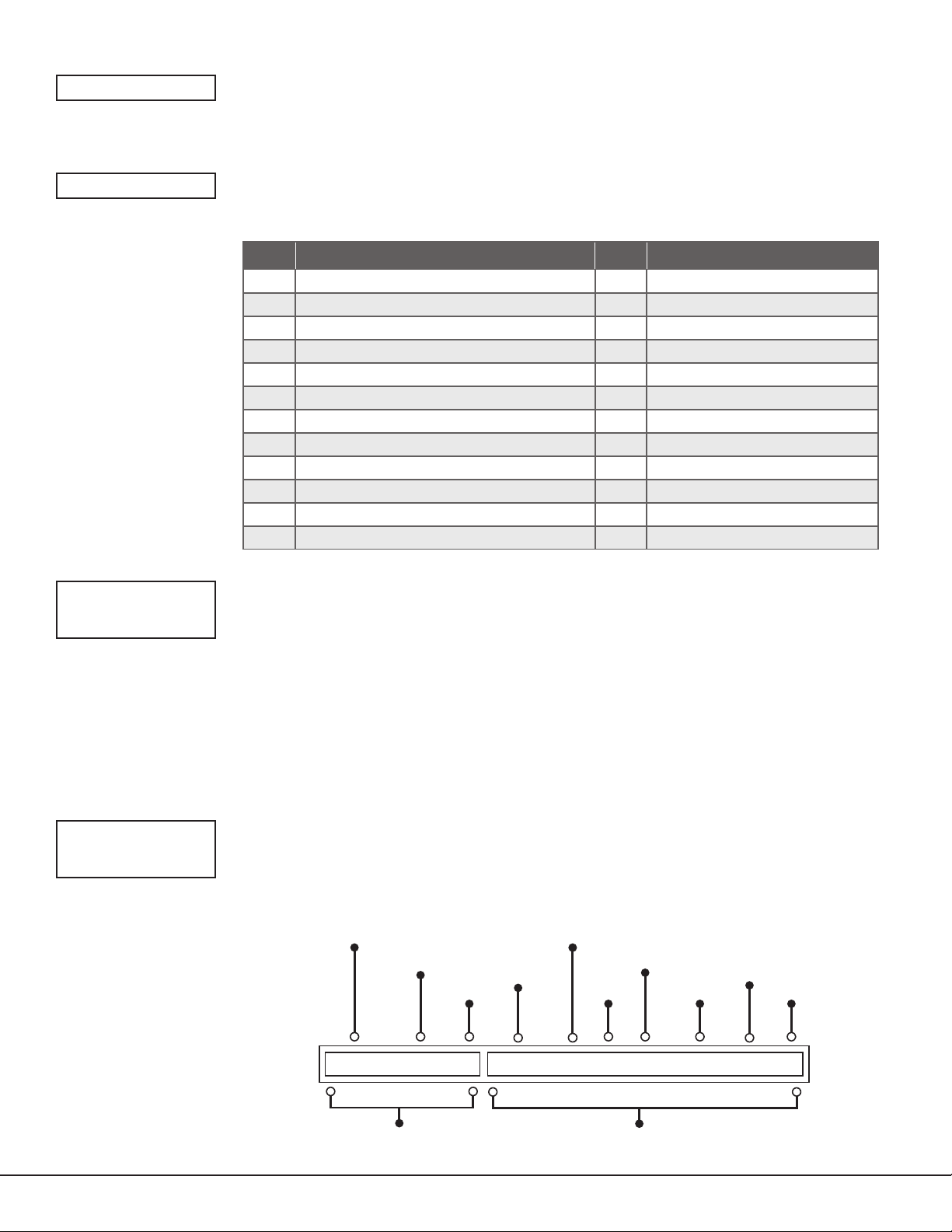
GMT CITY/TIME ZONE GMT CITY/TIME ZONE
0 London, Monrovia, Lisbon 12 Fiji, Marshall Island, Wellington
1 Cape Verde Island, Azores 13 New Cadelonia
2 Mid‑Atlantic 14 Guam, Sydney
3 Buenos Aires, Georgetown 15 Tokyo, Seoul
4 Atlantic Time (Canada), Caracas 16 Hong Kong, Singapore
5 Eastern Time (US, Canada) Bogota 17 Bangkok, Hanoi
6 Central Time (US, Canada) Saskatchewan 18 Dhaka, Almaty
7 Mountain Time (US, Canada), Edmonton 19 Islamabad, Karachi
8 Pacific Time (US, Canada), Tijuana 20 Abu Dhabi, Kazan
9 Alaska 21 Moscow, Bagdad
10 Hawaii 22 Eastern Europe
11 Midway Island, Samoa 23 Rome, Paris, Berlin
Table 6: GMT Time Zones
KEYPAD INPUT
Select NONE to allow zone4 to function as normally programmed. The default is NONE.
Select ECP to enable communication between the communicator and an Ademco/
Honeywell panel using the +Z4‑ terminals. Using the Ademco/Honeywell ECP Bus, the
communicator can add, delete, and change user codes as well as arm and disarm the
Ademco/Honeywell panel. The communicator will forward alarm messages from the
Ademco/Honeywell panel to the central station.
Select DSC to enable communication between the communicator and a DSC PowerSeries
panel using the Z4‑ terminal. Using the DSC bus, the communicator can add, delete,
and change user codes as well as arm and disarm the DSC panel. The communicator will
forward alarm messages from the DSC panel to the central station.
See Ademco/Honeywell ECP Connection for examples of panel wiring and necessary
Ademco/Honeywell panel programming.
CID FORMAT
DMP CID
Digital Monitoring Products
26
CID FORMAT
Select DMP to send CID messages as Serial 3 format. Select CID to send messages as DMP
string with raw CID message appended. Refer to Figure 16. Default is DMP.
This feature requires SCS‑VR Version 1.4.6 and higher or SCS‑150 Version 107 and higher.
The receiver sending
the message
The account number
of the DMP panel
The account number
CID Identifier
The message type
that identifies
the message as CID
of the host panel
The event code
for a Zone Fire Alarm
The new event
Partition
Number
Zone
Number
Checksum
9910 3155 c 5550 18 1 110 00 010 2
DMP String CID String
Figure 16: CID Format Option
DualCom
Programming and Installation Guide
Page 31
OUTPUT OPTIONS
OUTPUT OPTIONS
This option allows you to program communicator output options. Switched ground (open
collector) outputs are available using terminals O1 and O2 as the ground and your
panel
for power. Select from outputs1 or 2.
control
CO OUTS: ‑ ‑
CUTOFF TIME: 0
COMM FAIL OUT: 0
ARMED OUT: 0
RMT ARMG OUT: 0
CUTOFF OUTPUTS
Define the operation of the two on‑board outputs. For each programming option, enter
the output you wish to activate or 0 for no output. Either or both of the outputs can be
programmed here to turn off after the time specified in output cutoff time. To disable this
option, press any select area to clear the display of output numbers and then press CMD.
OUTPUT CUTOFF TIME
If a cutoff output is assigned, you can enter a cutoff time for the output to remain on up to
15minutes. If the output is turned off manually, the cut off time is reset. The cutoff time can
be 1‑15minutes. Enter 0 to provide continuous output.
Note: The output is cutoff within 60seconds of the programmed cutoff time.
The cutoff timer is shared by all outputs. If a second output trips, the timer is not reset.
Both outputs turn off when the original time expires.
COMMUNICATION FAILURE OUTPUT
This output/favorite turns on when the communicator fails to communicate with the
receiver. To turn off communication failure output, disarm the communicator. Enter 0 to
disable this output.
ARMED OUTPUT
This output/favorite turns on any time an area of the system is armed. The output turns off
when the system completely disarms. Enter 0 to disable this output.
REMOTE ARMING OUTPUT
When the system is armed or disarmed remotely from the Virtual Keypad App,
VirtualKeypad.com, Remote Link, or from a schedule, this output turns on momentary for
0.75seconds then turns off. This output can be used for panels that require a momentary
short to an arming zone to arm and a momentary short to disarm.
HEAT SAVER
TEMPERATURE: 0
COOL SAVER
TEMPERATURE: 0
HEAT SAVER TEMPERATURE
(DualComWZ only)
Enter the desired temperature setting for all Z‑Wave thermostats when the system
is armed ALL. When the system is disarmed, the thermostats return to their previous
settings. The range is 1‑99 degrees. Enter 0 to disable.
COOL SAVER TEMPERATURE
(DualComWZ Only)
Enter the desired temperature setting for all Z‑Wave thermostats when the system
is armed ALL. When the system is disarmed, the thermostats return to their previous
settings. The range is 1‑99 degrees. Enter 0 to disable.
DualCom
Programming and Installation Guide Digital Monitoring Products
27
Page 32
AREA INFORMATION
AREA INFORMATION
This option allows you to assign functions to the area of the communicator. All non‑24‑hour
zones must be assigned to an active area. See Zone Information for more information.
AREA NO: ‑
* UNUSED *
AUTO ARM NO YES
BAD ZONES: BYP
BYP FORC REF
AREA NUMBER
Enter the number of the area you wish to program. Select from areas 1‑6.
AREA NAME
Only those areas given names can have zones assigned to them. All others are marked
*UNUSED*. See Letters and Special Characters for more information.
To add an area name to the system, press any select area and enter up to 16characters for
the new name. Press CMD to continue. To mark an active area as unused, delete the old
name by pressing any select key then press CMD. The communicator automatically sets
the name as *UNUSED*. If you have already initialized the communicator, all areas will be
marked as *UNUSED*.
AUTOMATIC ARMING
Choose YES to allow this area to arm automatically according to the opening and closing
schedule. At arming, faulted zones are handled according to the option selected in bad
zones. If a closing report is sent, the user number is indicated as SCH on the SCS‑1R or
SCS‑VR receivers.
Choose NO to disable automatic arming for this area. The default is NO.
Bad Zones
At the time of automatic arming, some zones in the area may not be in a normal condition.
This option allows you to program the panel’s response to these bad zones. This option is
not displayed if AUTO ARM is NO.
BYP: All bad zones are bypassed. A report of the bypass is sent to the receiver if bypass
reports has been set as YES. The report indicates SCH as the user number.
FORC: All bad zones are force armed. Zones force armed in a bad condition are capable of
restoring into the system and reporting alarms if tripped. A report of the force arm is sent
to the receiver. The report indicates the user number as SCH.
REF: The automatic arming is refused and no arming takes place. Closing report is sent to
the receiver.
AUTO DIS NO YES
AUTOMATIC DISARMING
Choose NO to disable automatic disarming by schedule for this area. The default is NO.
Choose YES to allow this area to automatically disarm according to a schedule. If an
opening report is sent to the receiver, the user number is indicated as SCH.
Digital Monitoring Products
28
DualCom
Programming and Installation Guide
Page 33
ZONE INFORMATION
ZONE INFORMATION
This allows you to define the operation of each protection zone used in the system.
ZONE NO: ‑
* UNUSED *
ZONE TYPE: BLANK
‑‑ NT DY EX
FI PN EM SV
A1 A2 AR FV
ZONE NUMBER
The communicator has four zones to program. Enter the number of the zone you intend to
program. To program zone4, see Zones 1‑4 Input Connection. Press CMD to enter a zone
name. See Letters and Special Characters.
ZONE NAME
Press any select area and enter up to 16characters for the zone name. A name must be
given to each zone in the system. The zone name is sent to the receiver as part of a zone
event report. A zone that is not part of the system must be marked *UNUSED*. To mark
a zone unused, de lete the old name by pressing any select area, then press CMD. The
programmer auto matically pro grams the name as *UNUSED*. If you selected ZONES NO
YES to clear the communicator’s memory during initialization, the zones will already be
marked *UNUSED*. See Initialization.
ZONE TYPE
The zone type defines the response of the communicator to the zone being open or short.
When you assign a zone type to a zone, responses are made automatically for the zone.
There are 12zone types to choose from including Blank.
To select a new zone type, press any select area. The display lists the four zone types
shown below. When the zone type you want to select displays, press the select area below
or on the name.
Blank (‑‑), Night (NT), Day (DY), or Exit (EX). Press CMD to display additional zone types.
Fire (FI), Panic (PN), Emergency (EM), or Supervisory (SV). Press CMD to display additional
zone types.
Auxiliary 1 (A1), Auxiliary 2 (A2), Arming (AR), or Fire Verify (FV). Press the back arrow to
display the previous zone types.
If you select Blank, Night, Day, Exit, Auxiliary 1, or Auxiliary 2 as the zone type, the zone
must be assigned to an area. See Zone1‑4 Input Connection. If you select Fire, Panic,
Emergency, or Supervisory as the zone type, these are 24‑hour zones that are always
armed and no area assignment is needed.
AREA NO: 1
AREA: 1 ‑ ‑ ‑ ‑ ‑
Area Assignment
All non‑24‑hour zones are automatically assigned to area 1. Enter the area number from 1‑6
where this zone is being assigned.
Arming Zone Assignment
Specify the areas to be armed by the arming type zone. Press the appropriate numbers on
the keypad to assign areas 1‑6. When disarmed, all areas are disarmed.
DualCom
Programming and Installation Guide Digital Monitoring Products
29
Page 34
STYLE: TGL
TGL ARM DIS STEP
MNT
Style
Specify the style for the arming/disarming operation. The default style is TGL (Toggle).
Press any select area to display the style options. To view more style options, press CMD.
The following is a description of the action for each option condition.
TGL (Toggle): When the zone changes from normal to shorted, the programmed areas
toggle between the armed or disarmed condition. When restored to normal, no action
occurs. When the zone is opened from a normal (disarmed) state, trouble is reported.
When opened from a shorted (armed) state, an alarm is reported and the zone is disabled
until you disarm the area(s) from either the Virtual Keypad App, VirtualKeypad.com, or
Remote Link.
ARM: When the zone is shorted, the programmed area is armed. When restored to normal,
no action occurs. When the zone is opened from a normal (disarmed) state, trouble is
reported. When opened from a shorted (armed) state, an alarm is reported.
DIS (Disarm): A short will disarm the area. When restored to normal, no action occurs.
When the zone is opened from a normal (disarmed) state, trouble is reported.
STEP: A short will arm the areas. A normal condition will cause no action. An open
condition will disarm the areas. When using an arming/disarming keyswitch, locate the
keyswitch within the protected area.
MNT (Maintain): When the zone is shorted, the programmed area is armed. When restored
to normal, the area is disarmed and any alarm bells are silenced. When the zone is opened
from a normal (disarmed) state, trouble is reported. If opened from a shorted (armed)
state, an alarm is reported and the zone is disabled until you disarm the area from either
the Virtual Keypad App, VirtualKeypad.com, or Remote Link.
NEXT ZN? NO YES
ALARM ACTION . . .
DISARMED OPEN
MSG: ALARM
A T L ‑
NEXT ZONE
Choose YES to terminate the programming for a zone. You may enter a new zone number
when ZONE NO: ‑ appears on the display.
Choose NO to make changes to the alarm action for a zone.
ALARM ACTION
Change the default alarm characteristics of a zone type. If you selected the non‑24‑hour
zone type Blank, Night, Day, Exit, Auxiliary 1, or Auxiliary 2, the alarm action programming
begins with Disarmed Open. If you selected the 24‑hour zone type Panic, Emergency, or
Supervisory, the alarm action programming begins with Armed Open.
DISARMED OPEN
Define the action taken by the communicator when the zone is opened while the area is
disarmed. There are three actions to define: Message to Transmit, Output/Favorite Number,
and Output Action.
You must also make these selections for the Disarmed Short, Armed Open, and Armed
Short zone conditions.
MESSAGE TO TRANSMIT
You can send two report types to the receiver: Alarm and Trouble. These are represented
by the characters A and T. Press any select area to display the zone report options.
ALARM: Select A to allow an alarm report to be sent to the receiver. The zone name
appears in the communicator’s alarmed zones status lists.
TROUBLE: Select T to allow a trouble report to be sent to the receiver and the zone name
to appear in the communicator’s alarmed zones status lists.
LOCAL: Select L to prevent sending an alarm report to the receiver. The zone name
appears in the communicator’s alarmed zones status lists.
– (dash): Select – to prevent sending reports to the receiver. There is no display in the
communicator’s alarmed zones status list. Only the programmed output number activates.
OUTPUT NO:
0
Digital Monitoring Products
30
OUTPUT NUMBER
Specify an output/favorite on the communicator to activate with a zone condition. The
output/favorite can be activated regardless of the report to transmit or whether or not the
zone is programmed as local. An output activated by a non‑24‑hour armed zone is turned
off when the zone’s area is disarmed by a user. To enter an output number, press any select
area followed by the output number1 or2.
DualCom
Programming and Installation Guide
Page 35
ACTION:
STD PLS MOM
FLW
OUTPUT ACTION
Enter an output number to display this option. This option allows you to assign an output
action to the output. A description of the available output actions follows:
STD (steady): The output is turned on and remains on until the area is disarmed, an output
cutoff time expires, or the output is reset from the keypad user menu.
PLS (pulse): The output alternates one second on, one second off until the area is
disarmed, an output cutoff time expires, or the output is reset from the keypad user menu.
MOM (momentary): The output is turned on only once for one second.
FLW (follow): The output is turned on and remains on while the zone is in off, normal, or
bad condition. When the zone restores, the output is turned off.
After you have selected the message to transmit, the display prompts you for the same
three selections for Disarmed Short, Armed Open, and Armed Short conditions. If the zone
is a 24‑hour type, only the Armed Open and Armed Short conditions are displayed. When
you have programmed all of the zone conditions, the panel displays the swinger bypass
selection.
SWGR BYP NO YES
CRS ZONE NO YES
SWINGER BYPASS
Choose YES to allow the zone to be swinger bypassed by the communicator according to
the programming in swinger bypass trips and reset swinger bypass.
Choose NO to disable swinger bypassing for this zone.
How it works
If within one hour, a zone trips the total number of times as specified in swinger bypass
trips, the communicator bypasses it until the following conditions occur:
• The area in which the zone is assigned is disarmed.
• The zone is manually reset through the bypass zones keypad user menu function.
• The zone remains normal for one hour and reset swinger bypass is set to YES.
If the zone trips fewer than the specified times within one hour of the first trip, the bypass
trip counter returns to 0 and the process must be repeated. A report of the swinger bypass
is sent to the receiver if bypass reports is set to YES.
CROSS ZONE
Choose YES to enable cross zoning for this zone. Cross zoning requires this zone to trip
twice, or this zone and another cross‑zoned zone to trip, within a programmed time before
an alarm report is sent to the receiver. To operate correctly, all cross‑zoned zones need to
be programmed as the same zone type.
When a cross‑zoned zone trips, the output action assigned to the zone activates. The
cross zone time specified in system options begins to count down. See Cross Zone Time. If
another cross‑zoned zone in the system faults, or if the first zone restores and faults again
before the cross zone time expires, the bell turns on and the communicator sends an alarm
report.
If no other cross‑zoned zone in the system trips before the cross zone time expires, the
communicator sends only a fault report from the first zone to the receiver. If cross zone is
set to yes, a valid cross zone time must be programmed for this feature.
Choose NO to disable cross zoning for this zone. The default is NO.
RECEIVER ROUTING
NORMAL
NORM 1 2 BOTH
ZONE NO: ‑
DualCom
Programming and Installation Guide Digital Monitoring Products
RECEIVER ROUTING
This option displays if zone type is set for Auxiliary 1 or Auxiliary 2. Press any select area to
select the receiver routing for the selected zone.
Select NORM to send alarm and supervisory/trouble messages from this zone to receiver1
or receiver2 as programmed within the receiver in communications.
Select 1 to send alarm and supervisory/trouble messages from this zone to receiver1 only,
regardless of the programming for the receiver in communications.
Select 2 to send alarm and supervisory/trouble from this zone to receiver2 only, regardless
of the programming for that receiver in communications.
Select BOTH to send alarm and supervisory/trouble from this zone to both receivers,
regardless of the programming for either receiver in communications.
ZONE NUMBER
Enter the zone number you want to program next. Return to Zone Information and follow
the descriptions of each programming option. If all zones are programmed, press the back
arrow at the ZONE NO display to continue.
31
Page 36

STOP
STOP
STOP
Press any select area to exit the programmer function of the communicator. When
selected, the communicator performs an internal reset and exits the programmer.
SET LOCKOUT CODE
SET LOCKOUT CODE
SET LOCKOUT CODE
Press CMD at the stop option to display SET LOCKOUT CODE. This feature allows you to
program a special code that will be required to gain access to the communicator’s internal
programmer through the keypad.
Changing the Lockout Code
You can change this code at any time to any combination of numbers from 1‑5digits long
(1‑65535). Do not use leading zeros for the lockout code.
1. Press any select area. The keypad displays ENTER CODE .
2. Enter a 1‑5digit code and press CMD.
Note: Do not enter a number higher than 65535.
3. Enter the new lockout code you just entered in the keypad and press CMD. The
keypad displays CODE CHANGED.
Once you have changed the code, it is important that you write it down and store it in
a safe place. Lost lockout codes require the communicator to be sent back into DMP
for repair. You may cancel a lockout code by entering 00000 at the set lockout code
command option.
Digital Monitoring Products
32
DualCom
Programming and Installation Guide
Page 37

Z‑WAVE SETUP (DUALCOMWZ ONLY)
The system may include a DMP Z‑Wave controller. The Z‑Wave controller allows short range radio control of Z‑Wave
devices such as lighting control modules, thermostat controls, doors, and garage doors. Z‑Wave Setup allows you
to program the system to control the Z‑Wave devices. Users can control Z‑Wave devices from a smartphone, tablet,
or desktop computer using the Virtual Keypad app or VirtualKeypad.com. The available setup options are Add, List,
Remove, Favorites, Transfer, and Optimize.
• Select ADD to add a Z‑Wave device to your system.
• Select LIST to display a list of Z‑Wave devices already added and stored in your system.
• Select REMOVE to completely remove a Z‑Wave device from your system.
• Select FAV to add, edit or remove a favorite.
• Select XFER to transfer Z‑Wave device information from another manufacturer’s portable Z‑Wave controller to
your system.
• Select OPT to update communication with all Z‑Wave devices programmed on your system. OPT can
re‑establish communication after a Z‑Wave device has been moved to a different location.
Note: Only the master user code level can access Z‑Wave setup through the user menu to program Z‑Wave
devices. For information on adding Z‑Wave devices from the Virtual Keypad app, navigate to online help from the
Settings tab in the app.
Add Z‑Wave Devices (ADD)
This option allows you to add a Z‑Wave device to a system. Once added, a Z‑Wave device may be assigned to a
favorite.
1. Access the user menu.
2. Press CMD until ZWAVE SETUP displays.
3. Press any select area. The keypad displays ADD LIST REMOVE.
4. Select ADD. PROCESSING may briefly display. When PRESS BUTTON ON DEVICE TO ADD displays, press the
program button on the Z‑Wave device. See the Z‑Wave device’s documentation for more information.
5. When the device information is received by the system, the keypad beeps once and displays DEVICE FOUND.
6. Once added, the keypad displays the type of device and the default device name. Press CMD.
7. Press any select area and enter up to a 16 character custom name for the device.
8. Press CMD to store the new name.
Note: A maximum of 140 Z‑Wave devices can be added to the system. When the maximum number of devices
have been added, the keypad displays ZWAVE TABLE FULL and no additional Z‑Wave devices may be added
without removing some existing devices.
List Z‑Wave Devices (LIST)
This option allows you to edit the name of a Z‑Wave device or confirm radio communication with the Z‑Wave device.
When LIST is selected, the first Z‑Wave device stored in the system is displayed. Press CMD to view the remaining
devices. Lighting control modules are displayed first followed by doors and thermostat controls.
The available LIST options are: Rename and Status.
• Select RENAME to enter up to 16characters for a new device name.
• Select STATUS to confirm radio communication with the Z‑Wave device.
Rename Z‑Wave Devices
1. Access the user menu.
2. Press CMD until ZWAVE SETUP displays.
3. Press any select area. The keypad displays ADD LIST REMOVE.
4. Select LIST to display DEVICE LIST and the first Z‑Wave device stored. Press CMD to advance through the list
of Z‑Wave devices.
5. Press any select area to display DEVICE RENAME STATUS.
6. Select RENAME and enter up to 16characters for a new device name.
7. Press CMD to save the new Z‑Wave device name and return to the DEVICE LIST.
DualCom
Programming and Installation Guide Digital Monitoring Products
33
Page 38

Status of Z‑Wave Devices
1. Access the user menu. Press CMD until ZWAVE SETUP displays.
2. Press any select area. The keypad displays ADD LIST REMOVE.
3. Select LIST to display DEVICE LIST and the first Z‑Wave device stored. Press CMD to advance through the list
of Z‑Wave devices.
4. Press any select area to display DEVICE RENAME STATUS.
5. Select STAT US to confirm radio communication with the Z‑Wave device.
6. The device name and OKAY displays when the device stored in the system communicates.
7. Press CMD to return to the device list and display the next device in the list.
8. If the device stored in the system does not communicate, the device name and FAILED displays. Press CMD to
display REMOVE FAILED DEVICE.
9. Choose YES to remove the failed device from the system memory. Choose NO to leave the device in the system
memory and to return to the device list.
10. When the device has been removed, the device name and REMOVED is displayed and the system no longer
tries to communicate with the Z‑Wave device.
Remove Z‑Wave Devices (REMOVE)
Each Z‑Wave device added to your system remains in your system unless it is removed. This option allows you to
remove Z‑Wave devices from your system.
1. Access the user menu. Press CMD until ZWAVE SETUP displays.
2. Press any select area. The keypad displays ADD LIST REMOVE.
3. Select REMOVE. PROCESSING may briefly display. When PRESS BUTTON ON DEVICE TO REMOVE displays,
press the program button on the Z‑Wave device. The device name and REMOVED is displayed to indicate the
Z‑Wave device has been removed.
Favorites (FAV)
Z‑Wave devices can be grouped together to create a favorite. This option allows you to program up to 20 favorites
in your system and then add up to 25 Z‑Wave devices in a favorite. When activated from the FAVORITE user menu,
a command is sent to its Z‑Wave Devices. A favorite can only be activated or turned on. A separate favorite must be
created to change the conditions set by the first favorite.
For example, a favorite called “Movie Night” could lock the exterior doors, close the garage door, adjust the
temperature, and dim the lights in the family room to the desired level. Another favorite called “Wakeup” could then
turn on the lights, adjust the temperature, unlock the exterior doors, and raise the garage doors.
Adding a Favorite
1. Access the user menu. Press CMD until ZWAVE SETUP displays.
2. Press any select area. The keypad displays ADD LIST REMOVE.
3. Press CMD again to display FAV XFER OPT. Select FAV and FAVORITE NUMBER is displayed.
4. Enter a favorite number between 1 and 20 and press CMD. If the favorite number entered is unassigned,
*UNUSED* displays. If the favorite is already assigned, you may change the name or press the back arrow and
enter a new number.
5. Press any select area and a cursor displays. Enter a favorite name up to 16characters. To remove a favorite,
press CMD without entering a name.
6. Press CMD to save the favorite. ADD EDIT REMOVE displays.
Add Devices to Favorites
1. Access the user menu. Press CMD until ZWAVE SETUP displays.
2. Press any select area. The keypad displays ADD LIST REMOVE.
3. Press CMD again to display FAV XFER OPT. Select FAV and FAVORITE NUMBER is displayed.
4. Enter a favorite number between 1 and 20 and press CMD.
5. The favorite number and name displays. Press CMD and name the favorite. ADD EDIT REMOVE displays.
6. Select ADD and the first Z‑Wave device stored in the system that has not already been added to this favorite is
displayed. Remaining devices can be viewed by pressing CMD.
7. Press any select area to assign the displayed device to the favorite. The device name and the current device
settings display. When added to a favorite, a Z‑Wave device can be programmed to respond to various
ON/OFF/LOCK/UNLOCK/HEAT/COOL commands based on your desired settings.
Digital Monitoring Products
34
DualCom
Programming and Installation Guide
Page 39

Change Device Settings in Favorites
Lights
1. Press any select area at SETTING and ON OFF DIM displays. Press the select area under the desired setting.
2. For ON or OFF setting, when selected, the favorite name and the next Z‑Wave device stored in the system
displays.
3. For DIM setting, DIM LEVEL with the current setting displays. To change the setting, press any select area and
enter the new level (1‑10) and press CMD.
4. The favorite name and the next Z‑Wave device stored in the system displays.
Doors
Press any select area at SETTING and LOCK UNLOCK for doors and OPEN CLOSE displays for garage doors. To
change the setting, press the select area under the new setting. The favorite name and the next Z‑Wave device stored
in the system displays.
Thermostats
1. Press any select area at SYSTEM and OFF CL HT displays. To change the setting of OFF, COOL, or HEAT,
press the select area under the new setting.
2. Select OFF to display FAN SETTING.
3. Press any select area and ON AUTO displays. Press the select area under the desired new setting to change.
4. Select CL to display COOL.
5. To change the setting, press any select area, enter the new temperature and press CMD.
6. Press any select area and the keypad displays FAN SETTING.
7. Press any select area and ON AUTO displays. Press the select area under the desired new setting to change.
8. Select HT to display HEAT.
9. To change the setting, press any select area and enter the new temperature and press CMD.
10. Press any select area and the keypad displays FAN SETTING.
11. Press any select area and ON AUTO displays. Press the select area under the desired new setting to change.
12. The favorite name and the next Z‑Wave device stored in the system displays.
Note: A maximum of 25 devices can be assigned to each favorite. When attempting to add a device and the
maximum number of devices has been assigned, FAVORITE FULL is displayed. No additional Z‑Wave devices may
be added to this favorite. However, a new favorite may be created and devices added to the new favorite.
Edit Devices in Favorites
1. Access the user menu. Press CMD until ZWAVE SETUP displays.
2. Press any select area. The keypad displays ADD LIST REMOVE.
3. Press CMD again to display FAV XFER OPT. Select FAV and FAVORITE NUMBER is displayed.
4. Enter a favorite number between 1 and 20 and press CMD.
5. The favorite number and name displays. Press CMD and the favorite name and ADD EDIT REMOVE displays.
6. Select EDIT and the first Z‑Wave device stored in the favorite displays. Remaining devices can be viewed by
pressing CMD. Z‑Wave devices are displayed by device type; Lights first, followed by Doors, and Thermostats
last. By pressing CMD, you can scroll through the devices assigned to the selected favorite.
7. Press any select area to display the device name and the setting for the device.
8. Change settings as needed. Once the device settings have been entered, the favorite name and the next
Z‑Wave device stored in the selected favorite displays.
Remove Devices from Favorites
1. Access the user menu. Press CMD until ZWAVE SETUP displays.
2. Press any select area. The keypad displays ADD LIST REMOVE.
3. Press CMD again to display FAV XFER OPT. Select FAV and FAVORITE NUMBER is displayed.
4. Enter a favorite number between 1 and 20, press CMD.
5. The favorite number and name displays. Press CMD and the favorite name and ADD EDIT REMOVE displays.
6. Select REMOVE. The first Z‑Wave device in the favorite displays. Other devices can be viewed by pressing CMD.
7. Press any select area to remove the device from the favorite. REMOVE DEVICE FROM FAV? NO YES displays.
When YES is selected, the device is removed from the favorite.
DualCom
Programming and Installation Guide Digital Monitoring Products
35
Page 40

Transfer Controller (XFER)
This option allows the transfer of all existing Z‑Wave devices that are currently programmed in another manufacturer’s
Z‑Wave portable controller to your system. This operation will overwrite all Z‑Wave devices that are programmed in
your system. This option typically occurs at the time your DMP Z‑Wave controller is installed. Initiate the transfer at
the other manufacturer’s Z‑Wave portable controller after starting the transfer on the DMP keypad. Z‑Wave devices
are NOT overwritten until the transfer has been initiated at the other manufacturer’s Z‑Wave portable controller. The
transfer should not be stopped once the process has been initiated from the other manufacturer’s Z‑Wave portable
controller.
Transfer Operation
1. Access the user menu. Press CMD until ZWAVE SETUP displays.
2. Press any select area. The keypad displays ADD LIST REMOVE.
3. Press CMD again to display FAV XFER OPT.
4. Select XFER. The keypad displays XFER WILL DELETE EXISTING DEVICES then displays XFER CNTRL SURE?
YES NO.
5. Choose YES to allow receipt of Z‑Wave devices to your system. The keypad displays TRANSFERRING Z‑WAVE
DEVICES. Pressing the Back Arrow cancels the transfer.
Choose NO to exit the XFER menu and return to ZWAVE SETUP. All programming will still be intact on the
DMP Z‑Wave controller and will cancel the transfer.
6. Initiate the transfer at the other manufacturer’s Z‑Wave portable controller. All Z‑Wave devices are added
to the system with a default name (device type and number). A 16‑character name may be assigned to the
Z‑Wave devices after the transfer finishes. When the transfer is complete, the screen will display ZWAVE
SETUP.
Note: If TRANSMISSION FAILED displays on the screen, your system memory is cleared of all prior Z‑Wave
devices programming and will need to add each Z‑Wave device individually.
Optimize (OPT)
Select optimize (OPT) to update communication withe all Z‑Wave devices. Optimize can be used to re‑establish
communication after a Z‑Wave device has been moved to a different location. When OPT is selected, the
communicator makes three attempts to communicate with each Z‑Wave device. Z‑Wave devices that fail to
communicate during the optimize process are not removed from programming.
1. Access the user menu. Press CMD until ZWAVE SETUP displays.
2. Press any select area. The keypad displays ADD LIST REMOVE.
3. Press CMD again to display FAV XFER OPT.
4. Select OPT, the keypad displays OPTIMIZE while the system is searching for Z‑Wave devices.
5. The keypad will display OPTIMIZE SUCCESS when Z‑Wave devices have been retrieved.
6. Press CMD to return to ZWAVE SETUP.
Note: The keypad will display OPTIMIZE FAILED when communication with a Z‑Wave device is not established. Press
CMD to return to ZWAVE SETUP and attempt optimize again. If communication with a Z‑Wave device is not
re‑established during the optimize process, make sure the device is powered on. If the device that failed has
power, add a repeater between the communicator and the device.
Digital Monitoring Products
36
DualCom
Programming and Installation Guide
Page 41

APPENDIX
This section provides additional zone and system information.
ECP Passthru
Program Vista Keypad Device Address 20
1. Power down and then power up the Honeywell panel.
2. Within 1 minute of powering up the Honeywell panel, simultaneously press and hold the # and * buttons on the
keypad.
3. The keypad displays INSTALLER CODE. Enter the installer code (default is 4112), followed by 800.
4. Enter *193, then enter 1 0.
5. To save and exit programming, enter *99.
User Codes in the Ademco/Honeywell Panel
Because the communicator duplicates the panel’s user codes, existing user codes in the Ademco/Honeywell panel,
including master, must be added to the communicator. The DualCom must also have user 2 as a master using the
same user code as the host panel user 2. This is required to allow codes added via App/Browser to be sent to the host
panel. Any new user codes added to the communicator from the VirtualKeypadApp will be automatically entered in
the Ademco/Honeywell panel.
User codes from the Ademco/Honeywell panel that are designated as master or partition master should be configured
as master codes in the communicator.
If the Ademco/Honeywell panel is armed/disarmed from a keypad, the communicator reports an opening/closing
message by user0 to the central station.
When the communicator is armed by the VirtualKeypadApp or VirtualKeypad.com, the Ademco/Honeywell panel
is also armed and the communicator reports an opening message. If opening and closing reports are enabled in the
Ademco/Honeywell panel, a duplicate message will also be sent to the central station.
Note: Communicators with Version 194 and higher do not require you to log in to the VISTA panel with a master
code to manage user codes remotely.
Manually Configure Communication with the Ademco/Honeywell Panel
The following steps describe how to configure Ademco/Honeywell control panels to communicate with the
communicator. Only use these steps if programming isn’t configured automatically with ECP SETUP.
1. Program Position * 54: Enter 0. This enables no signaling delay.
2. Program Position * 55: Enter 1. This enables communication to the communicator.
3. Program Position * 84: Enter 0. This disables CP01 and allows remote Arm Away.
4. Program Position * 193: Enter 1 0. This enables the DualCom ECP Bus address.
If the Ademco/Honeywell panel fails to communicate with the communicator, program Position * 29 to enable the
long range radio on the Ademco/Honeywell panel.
DSC Passthru
Remote Programming
DSC panels allow a 6‑hour interval for remote programming connections after the panel is initially powered up.
After that interval expires, technicians can re‑enable DLS connection for another 6 hours by disarming the panel and
entering the following code combination: *6 + [master code] + 5.
1. Right‑click Remote Link and select Run as administrator.
2. If necessary, create the communicator account.
3. Double‑click the communicator account.
4. Minimize Remote Link.
5. Open DLS.
6. Double‑click the DSC panel.
7. Edit programming as needed, then press the Upload Programming button.
False Alarm Reduction
System Recently Armed report
The system recently armed report (S78) is sent when a burglary zone goes into alarm within two minutes of the
system being armed.
DualCom
Programming and Installation Guide Digital Monitoring Products
37
Page 42
Diagnostics Function
‑XX dBm
The communicator contains a diagnostics function that allows you to test the integrity of the cellular communication,
setup ECP and DSC Passthu, and check panel settings. To use diagnostics, reset the communicator and enter the
diagnostics code 2313 (DIAG).
Communication Status
This option tests the individual components of cellular communication. The selected test will proceed until the first
component failure or until all components have been tested with positive results. The test screen will display after
each component and will be displayed for twoseconds or until CMD has been pressed.
Cellular Signal Strength (CELL SIGNAL)
SIGNAL:
▐▐▐▐▐▐▐
Test the cellular signal strength of the nearest carrier tower. Press any select area to display
cell signal strength. The X’s represent the numerical value of the cell signal strength in
‑dBm. The bars represent signal strength 0‑7.
SIGNAL:
▐▐▐▐▐▐▐
COMNET123
Wi‑Fi Signal Strength (WIFI SIGNAL)
Test the Wi‑Fi connection with the network. Press any select area to display Wi‑Fi signal
strength. The X’s represent the numerical value of the signal strength in ‑dBm. The bars
represent signal strength 0‑7.
Panel Settings
Press a top row key to access the MAC address, serial number, model, and firmware version.
Serial Number
This number is the communicator serial number. Reference this number for communicator date‑of‑manufacture and
hardware version. Press any select area to display the serial number.
Model Number
This menu option displays the model number of the communicator.
Firmware Version
This menu option displays the firmware version number of the communicator and date it was released.
Contact ID Recvd
This displays DTMF digits dialed from the burglary control panel.
ECP Setup
Automatically program ECP Passthru settings. This option is only available when KYPD INPUT is set to ECP.
1. Ensure keypad address 20 is programmed into the VISTA panel. Ensure the ECP panel IP address is set as
default. Advance to ECP SETUP and press any select key or area.
2. At ECP SETUP VISTA 128? If the panel is a VISTA 128, select YES. If the panel is a dierent model, select NO.
3. At INST CODE, enter the ECP panel installer code and press CMD.
4. After configuration is finished, the keypad advances to GET ZONES. Press any select key or area.
As the communicator retrieves zones from the ECP panel, the number of zones is displayed and incremented as
ZONE CT (zone count).
DSC Setup
Automatically program DSC Passthru settings. This option is only available when KYPD INPUT is set to DSC.
1. Ensure the DSC panel IP address is set as default. Advance to DSC SETUP and press any select key or area.
2. At INST CODE, enter the DSC panel installer code and press CMD.
3. After configuration is finished, the keypad advances to GET ZONES. Press any select key or area.
4. At INST CODE, enter the DSC panel installer code and press CMD to retrieve zones.
As the communicator retrieves zones from the DSC panel, the number of zones is displayed and incremented as
ZONE CT (zone count).
Press any select key or area to initiate DSC SETUP. At INST CODE, enter the DSC panel installer code and press
CMD. After attempting to program the DSC panel, the menu advances to GET ZONES. Press any select key or area to
retrieve zones from the panel.
Exiting the Diagnostics program
Press CMD until STOP displays. Press any select area. The keypad returns to the status list display.
Digital Monitoring Products
38
DualCom
Programming and Installation Guide
Page 43
Using the 984 Command Function
When not in the programming menu, the function 984 + CMD can be entered at the keypad. The remote options
menu appears. This menu contains the following options:
NET
The communicator allows you to perform a test on each component of the network communication paths. While
the Status List displays, enter 984 and press CMD. The keypad display changes to NBR PICKUP NET CELL. Press the
select area under NET to allow the panel to perform a Communication Status Test.
Upon entry of a network path when prompted, the test runs and the results display on the keypad in the order they
were tested: LINK, DHCP, GATEWAY, DEST, NET COMM.
Note: If NET is not a communication option on the panel, NO NETWORK displays on the keypad and you are
returned to the Status List.
CELL
The communicator allows you to perform a test on each component of the cellular communication paths. While the
status list displays, enter 984 and press CMD. Press the select area under CELL to allow the communicator to perform
a communication status test. The keypad displays CELL IS BUSY if the modem is being tested from another keypad.
Upon entry of a cellular path when prompted, the test runs and the results display on the keypad in the order they
were tested: MODEM OPERATING, IDENTIFIED, TOWER DETECTED, REGISTERED, CONNECT SUCCESS, and
CELL COM GOOD. Press CMD to advance through the results. When the test is complete you are returned to the
status list. See Diagnostic Functions for a description of the cellular status results.
Using the Walk Test
The walk test feature allows a single technician to test all zones on the system. Conduct
the walk test within 30minutes of resetting the communicator. The walk test automatically
ends if no zones are tripped for 20minutes. TEST IN PROGRESS displays at all keypads.
When fiveminutes remain, TEST END WARNING displays. If any areas are armed, the walk
test does not start and SYSTEM ARMED displays.
WALK TEST
WALK TEST
TRIPS: XXX END
TEST END WARNING
SOUTH LOBBY
ZONE: 10 ‑FAIL
WALK TEST
To conduct the walk test, reset the communicator by momentarily pressing the reset
button. From the keypad, enter 8144. The keypad displays WALK TEST. If the system
is monitored , the system sends a system test begin report to the central station. All
programmed zones are included in the test.
TRIP COUNTER FOR WALK TEST (STD)
Displays the number of zone trips during the walk test. Each time a selected zone trips, the
keypad buzzes.
END ‑ Press this select area to stop the walk test. When the walk test ends or a 20 minute
timeout expires, a final sensor reset occurs. The system test end message is sent to the
receiver along with verify and fail messages for each zone under test. Faulted zones display
on the keypad.
TEST END WARNING
When no zones have been tripped and fiveminutes remain on the 20 minute walk test
timer, the keypad displays TEST END WARNING and the keypad tones. If no additional test
zone trips occur, the test ends and a final sensor reset automatically occurs. The system
test end message is sent to the receiver along with verify and fail messages for each zone
under walk test. Faulted zones display on the keypad.
FAILED ZONES DISPLAY
Each zone that did not trip at least once during the walk test displays on the keypad that
initiated the test. Any Panic (PN) or Supervisory (SV) 24‑hour zone that is faulted at the
end of the walk test displays a trouble condition for that zone regardless of the message
programmed for the open or short condition of the zone and a zone trouble is sent to the
receiver. Press CMD to display the next failed zone.
DualCom
Programming and Installation Guide Digital Monitoring Products
39
Page 44
Cross Zoning
Caution must be taken when cross zoning devices to ensure that the cross zone time is long enough to allow a trip of
both zones before it expires. A cross zone time that is too short may allow a trip of the zones and only a zone fault
report be sent to the central station.
When a cross zoned zone trips, a FAULT report is sent to the SCS‑1R or SCS‑VR receivers. When two cross zoned
zones trip within the cross zone time, both zones send ALARM signals to the receiver. For example, if zones 1 and 2
are cross zoned zones, and only zone 1 trips, a FAULT report is sent to the receiver for zone 1. If zone 1 trips and zone2
trips within the cross zone time, an ALARM report is sent to the receiver for zone1 and zone2.
Note: To operate correctly, all cross‑zone zones need to be programmed as the same zone type.
Z‑Wave Information (DualComWZ only)
DualComWZ communicators are security enabled Z‑Wave products and are designed to be used as primary
controllers. The XFER feature allows an existing 3rd party network to be transferred into the communicator.
The communicator can support Z‑Wave products from different vendors and product categories. It is recommended
to use DMP devices for best performance.
Z‑Wave terminology:
• Inclusion is the process of adding a device to the Z‑Wave network. The new device is ‘included’ into the Z‑Wave
network.
• Exclusion is the process of removing a device from the Z‑Wave network. The new device is ‘excluded’ from the
Z‑Wave network.
• Replication is the process of copying network information to another device (typically a Z‑Wave controller) in
the Z‑Wave network.
TEST ZWAVE
DEVICE LIST:
HALLWAY LIGHT
HALLWAY LIGHT
LIGHT 02 0/0
HALLWAY LIGHT
99/99 SUCCESSFUL
Z‑Wave Test Option (DualComWZ only)
This feature allows the installer to test
A successful test indicates a response from a device. Press any select area to view the
Z‑Wave device list.
Press CMD to advance through each Z‑Wave device and press any select area to begin the
test on the device displayed.
The name of the device displays above the device number. The current number of
successful communications followed by the total number of attempts displays to the right
of the device number. The test stops after 99 attempts.
Press CMD to view the final number of successful communications.
communicator
communication with Z‑Wave devices.
Digital Monitoring Products
40
DualCom
Programming and Installation Guide
Page 45

Arming/Disarming Ademco Vista Panels
The following steps describe how to configure the communicator to arm and disarm an Ademco Vista control panel
from a schedule or remotely from the Virtual Keypad App, VirtualKeypad.com, or Remote Link™ using the remote
arming output.
1. Connect output17 (far left pin on the 7pin header located in the middle of the PCB) to zone1 (Z1) on the
communicator. Connect a 1k ohm EOL resistor from zone1 to ground (G).
2. Connect output1 (O1) on the communicator to zone3 (terminal12) on the Vista control panel.
3. Begin programming by entering the installer code followed by 800. Press * and Field ? displays.
4. Program zone3 as an arming zone. Enter 56 and program the following:
a. Set to Confirm? ‑ Enter 0.
b. Enter Zn Num. ‑ Enter 03. Press * to continue.
c. Summary Screen: Zn ZT P RC HW:RT ‑ Press * to continue.
d. Zone Type ‑ Enter 77. Press * to continue.
e. Report Code 1st 01 2nd 00 10 ‑ Press * to continue.
f. Hardware Type ‑ Enter 0. Press * to continue.
g. Resp Time ‑ Enter 1. Press * to continue.
h. Summary Screen: Zn ZT P RC HW:RT ‑ Press * to continue.
i. Program Alpha ‑ Enter 0.
j. Enter ZN Num displays. Enter 00 to exit.
5. Program output17. Enter * or # displays. Press * and Field? displays. Enter 79 and program the following:
a. Enter output No ‑ Enter 17. Press * to continue.
b. Output Normally Low ‑ Enter 0. Press * to continue.
c. Enter Output No displays. Enter 00 to exit.
6. Define output17 actions. Enter * or # displays. Press * and Field? displays. Enter 80 and program the following:
a. Program output17 to turn on when armed Stay. Output Funct# ‑ Enter 01. Press * to continue.
• Summary Screen: 01 A E P Trig ‑ Press * to continue.
• Activated by: ‑ Enter 2. Press * to continue.
• Enter Zn Type ‑ Enter 20. Press * to continue.
• Output Action ‑ Enter 2. Press * to continue.
• Enter Output No. ‑ Enter 17. Press * to continue.
• Summary Screen: 01 A E P Trig ‑ Press * to continue.
b. Program output17 to turn on when armed Away. Output Funct# ‑ Enter 02. Press * to continue.
• Summary Screen: 02 A E P Trig ‑ Press * to continue.
• Activated by: ‑ Enter 2. Press * to continue.
• Enter Zn Type ‑ Enter 21. Press * to continue.
• Output Action ‑ Enter 2. Press * to continue.
• Enter Output No. ‑ Enter 17. Press * to continue.
• Summary Screen: 02 A E P Trig ‑ Press * to continue.
c. Program output17 to turn off when Disarmed. Output Funct# ‑ Enter 03. Press * to continue.
• Summary Screen: 03 A E P Trig ‑ Press * to continue.
• Activated by: ‑ Enter 2. Press * to continue.
• Enter Zn Type ‑ Enter 22. Press * to continue.
• Output Action ‑ Enter 0. Press * to continue.
• Enter Output No. ‑ Enter 17. Press * to continue.
• Summary Screen: 03 A E P Trig ‑ Press * to continue.
d. Output Funct# ‑ Enter 00. Press * to continue.
7. Enter * or # displays. Press * and Field? displays. Enter 99 to exit programming.
8. Programming the communicator.
a. Reset the communicator. Enter 6653.
b. Press CMD to output options. Press any select area.
c. Program output 1 in remote arming output. Press CMD to RMT ARMG OUT. Enter 1, then press CMD.
d. Press CMD to zone information. Press any select area and Zone No displays.
e. Enter 1. Press CMD.
f. Enter a zone name. Press CMD.
g. Program zone1 as an arming zone. Zone Type displays. Choose arming zone type AR. Press CMD.
h. Area: 1‑‑‑‑‑‑ displays. Press CMD.
i. Style: TOGGLE displays. Choose MNT.
j. Go to STOP then press and select key to save and exit programming.
DualCom
Programming and Installation Guide Digital Monitoring Products
41
Page 46

FCC NOTICE
This device complies with part 15 of the FCC Rules. Operation is subject to the following two conditions:
1. This device may not cause harmful interference.
2. This device must accept any interference received, including interference that may cause undesired operation.
The antenna(s) used for this transmitter must be installed to provide a separation distance of at least 20 cm from all
persons.
This equipment has been tested and found to comply with the limits for a Class B digital device, pursuant to part 15 of
the FCC Rules. These limits are designed to provide reasonable protection against harmful interference in a residential
installation. This equipment generates, uses and can radiate radio frequency energy and, if not installed and used
in accordance with the instructions, may cause harmful interference to radio communications. However, there is no
guarantee that interference will not occur in a particular installation.
If this equipment does cause harmful interference to radio or television reception, which can be determined by turning
the equipment off and on, the user is encouraged to try to correct the interference by one or more of the following
measures:
• Reorient or relocate the receiving antenna.
• Increase the separation between the equipment and receiver.
• Connect the equipment into an outlet on a circuit different from that to which the receiver is connected.
• Consult the dealer or an experienced radio/TV technician for help.
Changes or modifications not expressly approved by the party responsible for compliance could void the user’s
authority to operate the equipment.
If necessary, the installer should consult the dealer or an experienced radio/television technician for additional
suggestions. The installer may find the following booklet, prepared by the Federal Communications Commission,
helpful:
“How to Identify and Resolve Radio‑TV Interference Problems.”
This booklet is available from the U.S. Government Printing Office, Washington D.C. 20402
Stock No. 004‑000‑00345‑4
INDUSTRY CANADA
This device complies with Industry Canada license‑exempt RSS standard(s). Operation is subject to the following two
conditions: (1) this device may not cause interference, and (2) this device must accept any interference, including
interference that may cause undesired operation of the device.
Le présent appareil est conforme aux CNR d’Industrie Canada applicables aux appareils radio exempts de licence.
L’exploitation est autorisée aux deux conditions suivantes : (1) l’appareil ne doit pas produire de brouillage, et (2)
l’utilisateur de l’appareil doit accepter tout brouillage radioélectrique subi, même si le brouillage est susceptible d’en
compromettre le fonctionnement.
NFPA 72
(DualComNF Only)
This equipment should be installed in accordance with Chapter 29 of the National Fire Alarm Code,
ANSI/NFPA 72, (National Fire Protection Association, Batterymarch Park, Quincy, MA 02269). Printed information
describing proper installation, operation, testing, maintenance, evacuation planning, and repair service is to be
provided with this equipment.
Warning: Owner’s instruction notice, not to be removed by anyone except occupant.
Digital Monitoring Products
42
DualCom
Programming and Installation Guide
Page 47

Specifications
Primary Power Nominal 12VDC or 24VDC
Current Draw at 12VDC
Standby 64mA
Alarm 109mA Peak Cellular Communication
Current Draw at 24VDC
Standby 30mA
Alarm 82mA Peak Cellular Communication
Dimensions and Color
Housing Dimensions 5.50”W x 3.75”L x 1.00”H
Housing Color DualComNF: Red
DualComWZ: White
Ordering Information
DUALCOMW-LV Wi-Fi and LTE (Verizon)
DUALCOMW-LA Wi-Fi and LTE (AT&T)
DUALCOMWZ-LV Wi-Fi and LTE with Z-Wave (Verizon)
DUALCOMWZ-LA Wi-Fi and LTE with Z-Wave (AT&T)
DUALCOMNF-LV Network and LTE (Verizon)
DUALCOMNF-LA Network and LTE (AT&T)
DUALCOMN-LV Network and LTE (Verizon)
DUALCOMN-LA Network and LTE (AT&T)
Accessories
685-W Surface Mount Condiut Backbox
(white)
685-R Surface Mount Conduit Backbox
(red)
383 Replacement Dual Band Cellular
Antenna
330-DSC DSC Remote Programming Harness
XTL-CN 90-degree Connector
Compatibility
ECP Passthru
VISTA 15
VISTA 20
VISTA 21
VISTA 128
DSC Passthru
PC1616
PC1832
PC1864
Certifications
Cellular
FCC Part 15: XMR201707BG96
IC: 10224A-201709BG96
Z-Wave
FCC Part 15: CCKPC0207
IC: 5251A-PC0207
Wi-Fi
FCC Part 15: VW4-ATWINC1500
IC: 20266-WINC1500PB
Underwriters Laboratories (UL) Listed
DualComN
ANSI/UL 1610 Central Station Burglar
DualComNF
ANSI/UL 864 Fire Protective Signaling Systems
(CID Capture)
18205
Designed, engineered, and
manufactured using U.S. and global
components in Springfield, MO.
LT-1859 20421
I N T R U S I O N F I R E A C C E S S N E T W O R K
2500 North Partnership Boulevard
Springfield, Missouri 65803-8877
800.641.4282 | DMP.com
 Loading...