

DNP CX-120 Service Manual
KAS-T089
June 2005
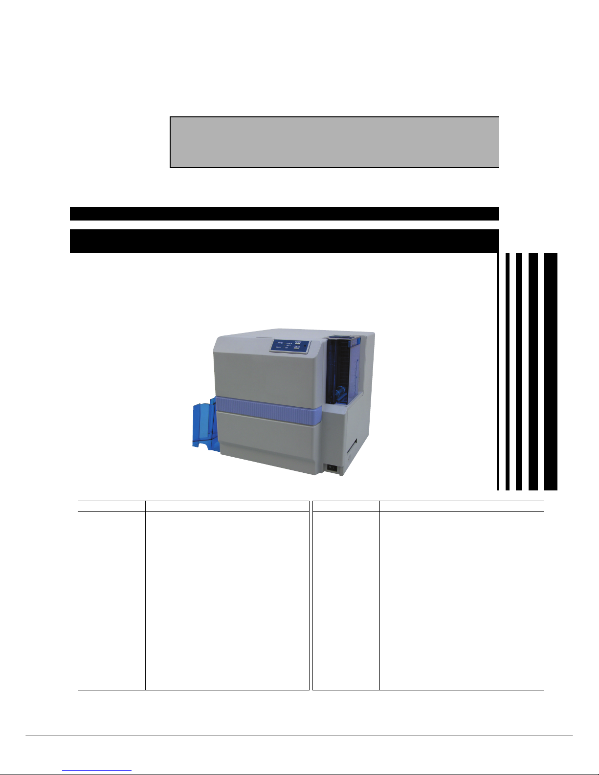
DIRECT DYE SUBLIMATION PRINTER
SERVICE MANUAL
CX-120
DNP
SPECIFICATIONS
䡵 Specifications and appearance of this unit may be changed for the purpose of product improvement without
prior notice.
Item Description
Recording Mode Dye sublimation printing
Paper Feed Mode
Automatic feeding
Recording Density
300 dpi
Color 256 gradations per color
Printing Time Approx. 20 seconds (Single-sided printing in
standard mode for all of YMC, Resin K and
OP, encoding time excluded)
Interface USB2.0 Hi-Speed (USB-IF certified product)
Usage Temperature : 15°C – 30°C
Environment Humidity : 35% – 70%
(without condensation)
Storage Environment
Temperature : -15°C – 55°C
Humidity : 20% – 80%
Power Supply AC 100 – 120 V (tolerance ±10%)
AC 220 – 240 V (tolerance ±10%)
Power 1.8 A (100 V)
Consumption 0.9 A (200 V)
Mass 12kg and below (excluding MG/IC encoder)
15kg and below (including MG/IC encoder)
Dimension Approx. 299 (W) x 311 (D) x 308 (H)mm
Accessories Power Cord :
AC120V
(Dark gray: North America)
1
AC200V (Europe) 1
Instruction Manual : English CD 1
Startup Guide
: English 1
Cleaning Card 1
Protection Card 1
USB Cable (1.5 m) 1
Consumable Cleaning Card 10 pcs / set (CX-120CC1)
Items Cleaning Kit (CX210-CKIT1)
Cleaning Unit (CX-120CL1)
Thermal Head (CX-120HD1)
Ink Ribbon
YMCKO 750screen pages (CY-15C-75)
YMCKOK 600 screen pages (CY-16K-60)
Optional Items Card Cassette (CX-120HP1)
Hand Gloves
M Size (U105-M)
L Size (U105-L)
Laminator Unit (CL-500)
Item Description

䡵 IMPORTANT SAFETY PRECAUTIONS
䡵 Startup Guide
Notes for safe operation ...................................................... 5
Before use ........................................................................... 7
Printer Characteristics ................................................... 7
Checking Accessories ................................................... 7
Content of Attached CD-ROM ....................................... 7
Protection of Color Printing Part .................................... 7
Handling the Ink Ribbon and Card ................................ 7
Cautions for Handling................................................. 7
Storage Method ......................................................... 7
Storage and Handling of Card After Printing .............. 8
Purchase of Ink Ribbon and Card .............................. 8
Escape Clause .............................................................. 8
Part Names ......................................................................... 9
(Front / Right) ............................................................. 9
(Rear / Left) ................................................................ 9
(When Printer Door is Open) ..................................... 9
Setup ................................................................................. 10
Location for Installation................................................ 10
Setting Up the Printer .................................................. 10
Connecting the Laminator ........................................ 10
Connecting the Power Cord ..................................... 11
Mounting the Card Stacker ...................................... 11
Ejection of Card ....................................................... 11
Setting the Ink Ribbon .............................................. 12
Adjusting Card Thickness ........................................ 14
Setting the Card ....................................................... 14
When Using a Magnetic Card .................................. 16
When Using a Contact-type IC Card ........................ 16
Supply of Card ......................................................... 16
Connecting the USB Cable.......................................... 17
Connecting Multiple Printers ....................................... 17
Installation of Software ...................................................... 18
Connecting to the Host Computer ............................... 18
About software ......................................................... 18
Operation Environment ............................................ 18
Installation of USB Driver - WindowsXP ...................... 19
Installation of USB Driver - Windows2000................... 20
Installation of CX-120 Status Monitor .......................... 21
Checking Connection with the Host Computer ................. 22
How to read the Instruction Manual (Electronic Manual) .. 23
Content of the Instruction Manual (electronic manual) 23
Maintenance...................................................................... 24
Cleaning the Cleaning Roller ....................................... 24
Cleaning the Thermal Head......................................... 25
Cleaning the Fan Filter ................................................ 25
Cleaning the Card Transport Roller ............................. 26
Cleaning the Magnetic Head ....................................... 27
After Maintenance ....................................................... 27
Troubleshooting (Simplified Version) ................................. 28
Action for Error Code List ............................................ 28
Removing Jammed Card ............................................. 29
Feed Jam ................................................................. 29
When there are frequent feed jams.......................... 29
Jam inside the printer ............................................... 29
A. When card is at the right (near inverter) .............. 30
B. When card is at the left (near printing unit) .......... 31
CONTENTS
C. When card can barely be seen from
the encoding unit .................................................. 31
Jam Inside Laminator ............................................... 31
Procedures for Changing Thermal Head .......................... 32
Checking After Changing Thermal Head ..................... 35
Consumable/Optional Items .............................................. 36
Memo .......................................................................... 37~40
Software use permission contract .............................. P1~P4
䡵 INSTRUCTIONS
Operating the Printer ........................................................... 2
LED Display ................................................................... 2
Names of Various Sections on Control Panel ................ 2
Button Control ............................................................... 3
Initialization .................................................................... 4
Test print using the printer alone ................................... 4
Differences Between Printing Modes .................................. 4
How to Use the Status Monitor ........................................... 5
Screen Configuration ..................................................... 5
Monitoring Printer Status ............................................... 6
Ready Status Display ................................................. 7
Error Status Display ................................................... 7
Other Status Display .................................................. 7
Changing Printer Settings ................................................... 8
Checking the Media and Printing Status ............................. 9
Display When Ink is Unknown ........................................... 10
Checking Printer Configuration ......................................... 11
Resetting the [No. of Cards Issued] Item .......................... 12
Test Printing ...................................................................... 12
Upgrading Firmware.......................................................... 13
Software Upgrade ............................................................. 14
Software Licensing Agreement.................................... 14
Update of USB Driver - WindowsXP ........................... 14
Update of USB Driver - Windows2000 ........................ 15
Update of CX-120 Status Monitor ............................... 18
Uninstalling Software ........................................................ 19
Deletion of USB Driver - WindowsXP .......................... 19
Detetion of USB Driver - Windows2000 ...................... 20
Deletion of CX-120 Status Monitor .............................. 21
Troubleshooting (Detailed Version) ................................... 22
Internal Configuration .................................................. 22
List of Error Codes and Corresponding Actions .......... 23
When ink ribbon is torn ................................................ 25
Problems Related to Printing ....................................... 25
Problems related to Color Printing .............................. 26
Problems Related to Text Printing ............................... 27
Problems Related to Protective Layer (OP) ................. 28
Actions to Take When Printer Fails to Start Up ............ 28
Version Upgrade ............................................................... 29
Specifications .................................................................... 30
Main Specifications ..................................................... 30
External Dimension ..................................................... 30

䡵 SERVISE MANUAL
MODEL NAME .................................................................... 1
1. DETAILED SPECIFICATIONS .................................. 1
BLOCK DIAGRAM .............................................................. 2
1. BLOCK DIAGRAM OF ENTIRE UNIT ...................... 2
2. CONNECTION DIAGRAM ........................................ 3
LAYOUT OF KEY PARTS .................................................... 4
1. FRONT: HEAD, FEED ROLLER, TURNOVER UNIT
AND SENSORS ........................................................ 4
2. REAR: MOTOR, FAN AND SENSORS....................... 5
3. BOARDS AND POWER SOURCES ......................... 6
4. MG / IC UNIT ............................................................ 7
DISMANTLING KEY PARTS ............................................... 8
1. LAYOUT DIAGRAM DURING MAINTENANCE ........ 8
2. DISMANTLING EXTERNAL PARTS AND
REFERENCE WIRING DIAGRAM ............................ 8
2.1 Dismantling the Top Cover ................................. 8
2.2 Dismantling the Front Panel ............................... 8
2.3 Reference Wiring Diagram ................................. 9
3. DISMANTLING THE MG / IC UNIT ........................ 10
4. SEPARATING THE CHASSIS AND MECHANICAL
UNIT AND DISMANTLING BOARDS ..................... 10
4.1 Dismantling the Chassis, Mechanical Unit and
Rear Panel ....................................................... 10
4.2 Dismantling Boards and Power Supply Units ... 11
4.2.1 Dismantling the DAD Board .................. 11
4.2.2 Dismantling the Drive Board .................. 11
4.2.3 Dismantling the Main Board .................. 12
4.2.4 Dismantling the Power Circuit Board ..... 12
5. DISMANTLING THE MOTOR ASSEMBLY ............. 13
5.1 Dismantling the Turn Motor Assembly .............. 13
5.2 Dismantling the Stepping Motor Assembly ...... 13
5.3 Dismantling the DC Motor ................................ 14
6. DISMANTLING THE TURNOVER UNIT ................. 14
7. DISMANTLING THE HEAD PRESS ASSEMBLY ... 14
MECHANICAL OPERATIONS .......................................... 15
1. INITIALIZE OPERATION ........................................ 15
2. FEED OPERATION ................................................. 15
3. PRINT OPERATION ............................................... 17
4. MG OPERATION .................................................... 19
5. IC OPERATION ....................................................... 19
TROUBLESHOOTING ...................................................... 20
1. ERROR CODE LIST AND CORRESPONDING
SERVICING PROCEDURES .................................. 20
MAINTENANCE ................................................................ 21
1. CLEANING.............................................................. 21
2. GREASING ............................................................. 21
3. LIST OF REPLACEABLE PARTS ........................... 21
ITEMS FOR ADJUSTMENT ............................................. 22
1. POWER SUPPLY VOLTAGE ADJUSTMENT .......... 22
MG / IC ENCODING UNIT ................................................ 23
1. MG/ IC ENCODER SPECIFICATIONS ................... 23
1.1 Magnetic Encoding Unit Specifications ............ 23
1.2 General Equipment Specifications ................... 23
2. BLOCK DIAGRAM .................................................. 24
2.1 MG / IC Unit Block Diagram ............................. 24
2.2 Connection Diagram ........................................ 25
3. REPLACING THE MG / IC ENCODING UNIT ........ 26
3.1 Repair Services................................................ 26
3.2 Replacement Procedure .................................. 26
3.3 DIP Switch ........................................................ 28
ASSEMBLY DIAGRAM AND PARTS LIST ........................ 29
1. CAUTIONS ............................................................. 29
2. ASSEMBLY DIAGRAM AND PARTS LIST .............. 30
Exploded Head Press Assembly Diagram .............. 30
Exploded Frame Assembly Diagram ....................... 31
Exploded Frame (Center Frame) Assembly
Diagram .................................................................. 32
Exploded Bottom Assembly Diagram ..................... 33
Exploded Turnover Unit Assembly Diagram ............ 34
Exploded Turn Motor Assembly Diagram ................ 35
Exploded Mechanical Assembly (Bottom) Diagram ... 36
Exploded Mechanical Assembly (Feed 1)
Diagram .................................................................. 37
Exploded Mechanical Assembly (Feed 2)
Diagram .................................................................. 38
Exploded Mechanical Assembly (Turn Unit)
Diagram .................................................................. 39
Exploded Mechanical Assembly (Press) Diagram.... 40
Exploded Mechanical Assembly (Wind) Diagram..... 41
Exploded Mechanical Assembly (Motor) Diagram.... 42
Exploded Mechanical Assembly (Fan) Diagram ..... 43
Exploded Mechanical Assembly (Turn Motor)
Diagram .................................................................. 44
Exploded PWB Assembly (DAD) Diagram .............. 45
Exploded PWB Assembly (Drive) Diagram ............. 46
Exploded PWB Assembly (RF-ID) Diagram............ 47
Exploded PWB Assembly (Power) Diagram ........... 48
Exploded PWB Assembly (Main) Diagram ............. 49
Exploded Hopper Base Assembly Diagram ............ 50
Exploded Front Panel Assembly Diagram............... 51
Exploded Final Assembly (MG/IC) Diagram ........... 52
Exploded Final Assembly (Front) Diagram ............. 53
Exploded Final Assembly (Rear 1) Diagram ........... 54
Exploded Final Assembly (Rear 2) Diagram ........... 55
Exploded Final Assembly (Top Cover) Diagram ..... 56
Exploded Annex Assembly (Attachments)
Diagram .................................................................. 57
Exploded Annex Assembly (Packaging) Diagram ... 58
Exploded Packing Assembly Diagram .................... 59
3.
MG / IC UNIT ASSEMBLY DIAGRAM AND PARTS LIST ...
60
Exploded MG Unit Assembly Diagram.................... 60
SAFETY PRECAUTION
Important Safety Precautions
Prior to shipment from the factory, JVC products are strictly inspected to conform with the recognized product safety and electrical codes of the
countries in which they are to be sold. However, in order to maintain such compliance, it is equally important to implement the following precautions
when a set is being serviced.
Fig.1
1. Locations requiring special caution are denoted by labels and inscriptions on the cabinet, chassis and certain parts of the product.
When performing service, be sure to read and comply with these
and other cautionary notices appearing in the operation and service manuals.
2. Parts identified by the ! symbol and shaded ( ) parts are
critical for safety.
Replace only with specified part numbers.
Note: Parts in this category also include those specified to com-
ply with X-ray emission standards for products using
cathode ray tubes and those specified for compliance
with various regulations regarding spurious radiation
emission.
3. Fuse replacement caution notice.
Caution for continued protection against fire hazard.
Replace only with same type and rated fuse(s) as specified.
4. Use specified internal wiring. Note especially:
1) Wires covered with PVC tubing
2) Double insulated wires
3) High voltage leads
5. Use specified insulating materials for hazardous live parts. Note
especially:
1) Insulation Tape 3) Spacers 5) Barrier
2) PVC tubing 4) Insulation sheets for transistors
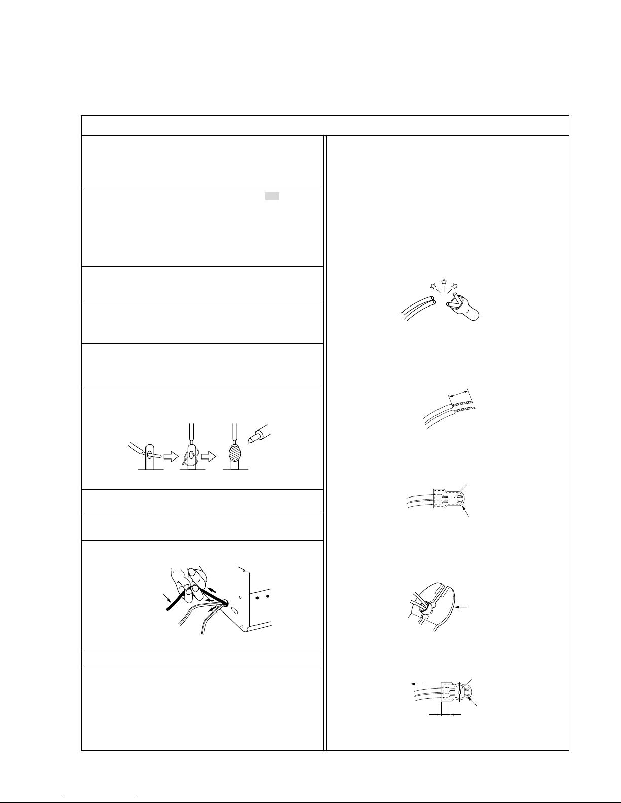
6. When replacing AC primary side components (transformers, power
cords, noise blocking capacitors, etc.) wrap ends of wires securely
about the terminals before soldering.
Power cord
Fig.2
10. Also check areas surrounding repaired locations.
11. Products using cathode ray tubes (CRTs)
In regard to such products, the cathode ray tubes themselves, the
high voltage circuits, and related circuits are specified for compliance with recognized codes pertaining to X-ray emission.
Consequently, when servicing these products, replace the cathode ray tubes and other parts with only the specified parts. Under
no circumstances attempt to modify these circuits.
Unauthorized modification can increase the high voltage value and
cause X-ray emission from the cathode ray tube.
12. Crimp type wire connector
In such cases as when replacing the power transformer in sets
where the connections between the power cord and power transformer primary lead wires are performed using crimp type connectors, if replacing the connectors is unavoidable, in order to prevent
safety hazards, perform carefully and precisely according to the
following steps.
1) Connector part number : E03830-001
2) Required tool : Connector crimping tool of the proper type which
will not damage insulated parts.
3) Replacement procedure
(1) Remove the old connector by cutting the wires at a point
close to the connector.
Important : Do not reuse a connector (discard it).
Fig.7
cut close to connector
Fig.3
(2) Strip about 15 mm of the insulation from the ends of the
wires. If the wires are stranded, twist the strands to avoid
frayed conductors.
15 mm
Fig.4
(3) Align the lengths of the wires to be connected. Insert the
wires fully into the connector.
Connector
Metal sleeve
Fig.5
(4) As shown in Fig.6, use the crimping tool to crimp the metal
sleeve at the center position. Be sure to crimp fully to the
complete closure of the tool.
I
•
Precautions during Servicing
7. Observe that wires do not contact heat producing parts (heatsinks,
oxide metal film resistors, fusible resistors, etc.)
8. Check that replaced wires do not contact sharp edged or pointed
parts.
9. When a power cord has been replaced, check that 10-15 kg of
force in any direction will not loosen it.
1.25
2.0
5.5
Crimping tool
Fig.6
(5) Check the four points noted in Fig.7.
Not easily pulled free
Crimped at approx. center
of metal sleeve
Conductors extended
Wire insulation recessed
more than 4 mm
S40888-01
SAFETY PRECAUTION
•
Safety Check after Servicing
Examine the area surrounding the repaired location for damage or deterioration. Observe that screws, parts and wires have been returned
to original positions, Afterwards, perform the following tests and confirm the specified values in order to verify compliance with safety
standards.
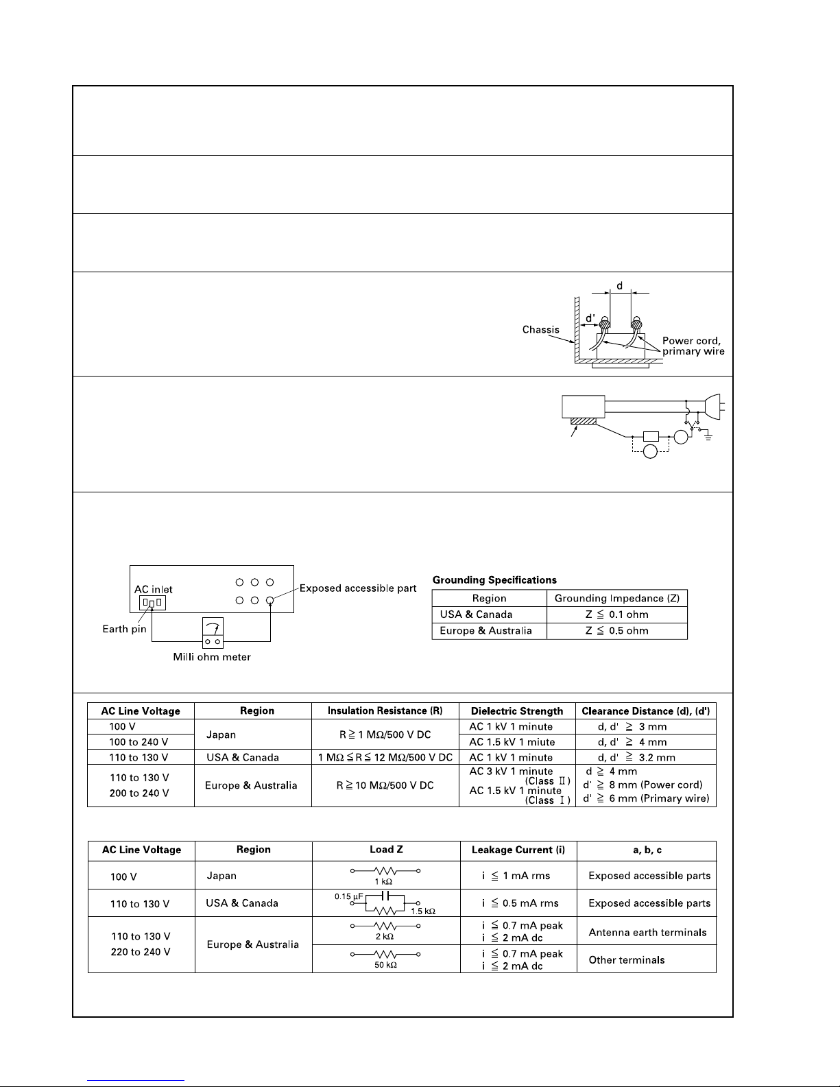
1. Insulation resistance test
Confirm the specified insulation resistance or greater between power cord plug prongs and externally exposed parts of the set (RF terminals, antenna terminals, video and audio input and output
terminals, microphone jacks, earphone jacks, etc.). See table 1 below.
2. Dielectric strength test
Confirm specified dielectric strength or greater between power cord plug prongs and exposed accessible parts of the set (RF terminals, antenna terminals, video and audio input and output terminals,
microphone jacks, earphone jacks, etc.). See table 1 below.
3. Clearance distance
When replacing primary circuit components, confirm specified clearance distance (d), (d’) between soldered terminals, and between terminals and surrounding metallic parts. See table 1
below.
4. Leakage current test
Confirm specified or lower leakage current between earth ground/power cord plug prongs and
externally exposed accessible parts (RF terminals, antenna terminals, video and audio input and
output terminals, microphone jacks, earphone jacks, etc.).
Measuring Method : (Power ON)
Insert load Z between earth ground/power cord plug prongs and externally exposed accessible
parts. Use an AC voltmeter to measure across both terminals of load Z. See figure 9 and following
table 2.
5. Grounding (Class 1 model only)
Confirm specified or lower grounding impedance between earth pin in AC inlet and externally exposed accessible parts (Video in, Video out,
Audio in, Audio out or Fixing screw etc.).
Measuring Method:
Connect milli ohm meter between earth pin in AC inlet and exposed accessible parts. See figure 10 and grounding specifications.
Fig. 10
Fig. 9
Fig. 8
Tab le 1 Specifications for each region
Tab le 2 Leakage current specifications for each region
Note: These tables are unofficial and for reference only. Be sure to confirm the precise values for your particular country and locality.
II
S40888-01
ab
c
V
A
Externally
exposed
accessible part
Z

BLOCK DIAGRAM
1
Alphabets and numerals after the model name are used to distinguish the different regions of use and specifications.
ID Label: CX-120*-#-DN
1. DETAILED SPECIFICATIONS
*1 : * Portion — Region of use
U ........... North America (100 – 120 V)
E ........... Europe (220 – 240 V)
*2 : # Portion — Internal Option
Nil .......... No option (Standard model)
A ........... Equipped with JIS magnetic encoder / IC contact
B ........... Equipped with ISO magnetic encoder / IC contact
MODEL NAME
BLOCK DIAGRAM
2
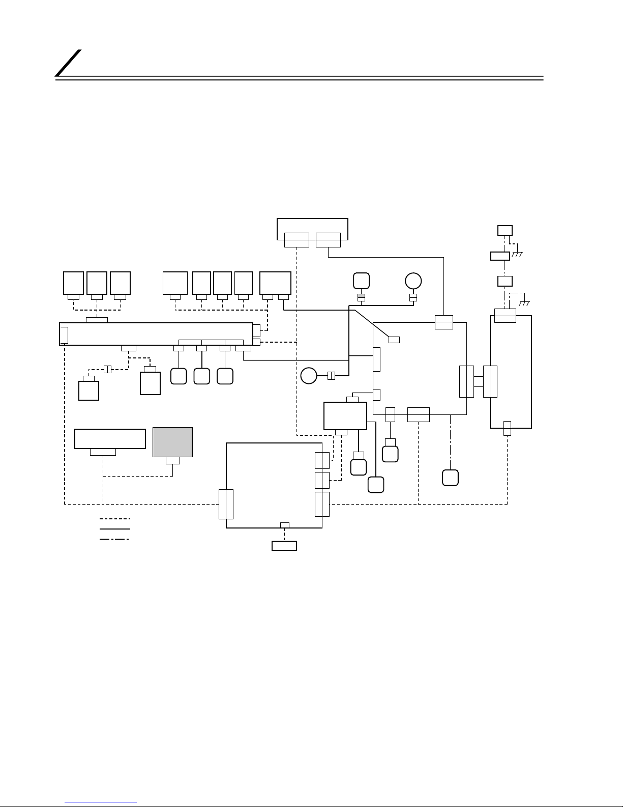
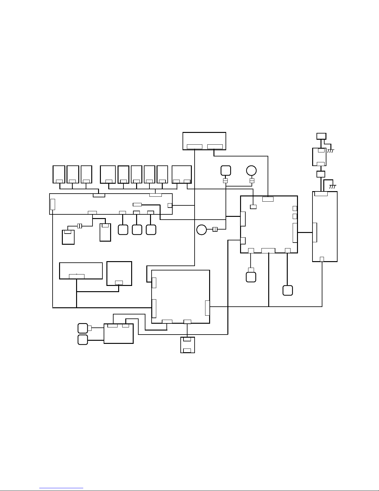
BLOCK DIAGRAM
1. BLOCK DIAGRAM OF ENTIRE UNIT
No Card
PCBCLPCB
Tu rn
PCB
Conn PCB
Print
PCB
DAD PCB
Main PCB
T pos
PCB
FG
PCB
Head
CAMP CB
Tu rn
over
motor
Hopper Motor
Tu rn
over
feed
motor
Head
motor
Inter Lock
PCB
Ink
PCB
Front PCB
MG PCB
MG
Motor
Soleoid
Rear FAN
Card feed
Motor
Head
PCB
Head
FAN
Ink motor
Inlet
BLEED
PCB
Powe r
Switch
RFID
Module
Exit
PCB
Drive PCB PSU
DC5V
DC24V
AC100-240V Primary
BLOCK DIAGRAM
3
2. CONNECTION DIAGRAM
Main PWB
Drive PWB
PSU
Head PWB
Inlet
Power
Switch
Conn PWB
Front PWB
RFID
Module
DADPWB
Inter LocK
PWB
Rear FAN
Head FAN Ink motor
Turn
over
motor
Head
motor
Turn
over
feed
motor
Hopper Motor
No Card
PWB
FG
PWB
Card feed
Motor
Head
CAMPWB
CL
PWB
Turn
PWB
Ink2
PWB
Tpos
PWB
Print
PWB
Exit
PWB
BLEED
PWB
MG PWB
MG
Motor
Solenoid
CN71
CN77 CN79 CN78
CN72
CN70
CN73
CN74CN76
CN7
CN4
CN8 CN5
CN6
CN35
CN23 CN21 CN32
CN33
CN36
CN37
CN24
CN2
CN3
CN1
CN30
CN34
CN100
CN101
CN53 CN52
CN97
CN98
CN96
J2
CN82 CN99 CN87 CN95 CN84 CN85 CN90 CN94 CN93
CN92
CN83
KW
S0735
CN88
Ink1
PWB
KWS0723
KWS0724
KWS0725
KWS0726
KWS0727
KWR18418
KWS0728
KWS0729
KWR15208
KWS0730
KWR15205
KWS0731
KWS0732
KW
R15209
KWS0733
KWS0734
KWS0736
KWR16003
KWS0737
J1 J3
LAYOUT OF KEY PARTS
4
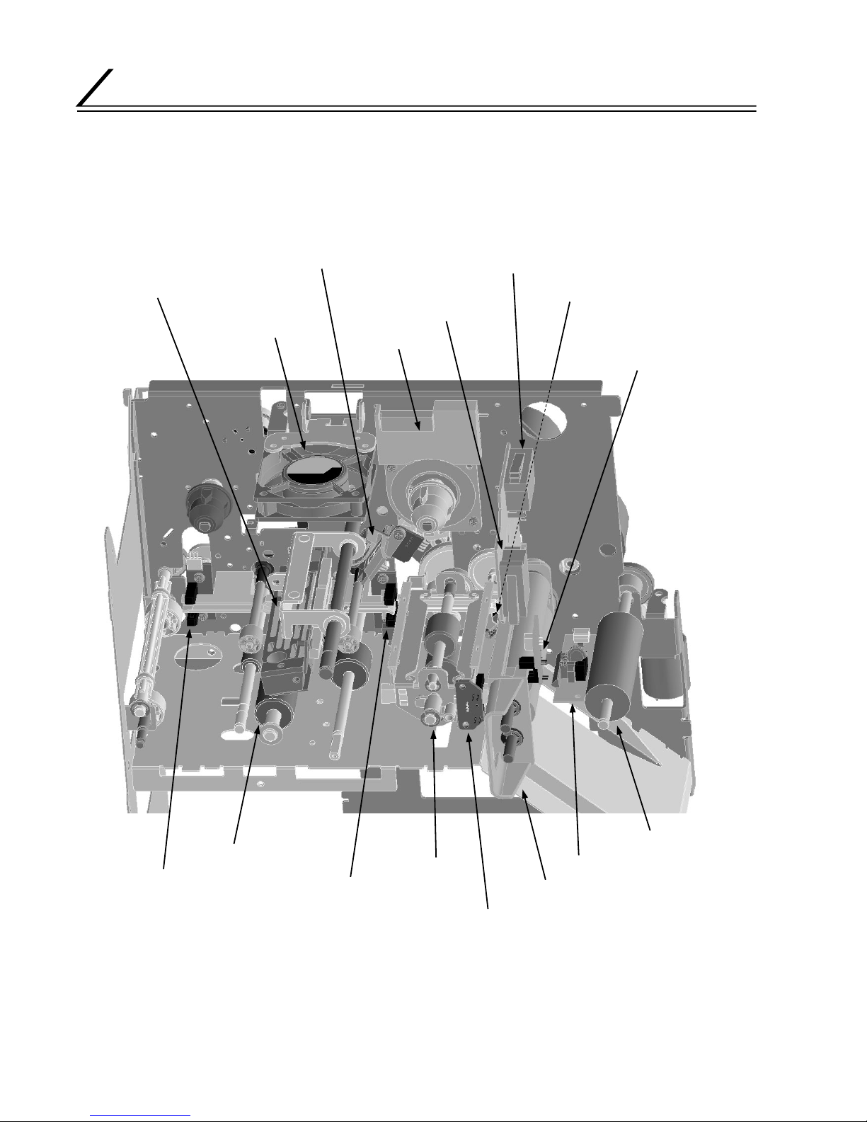
1.
FRONT: HEAD, FEED ROLLER, TURNOVER UNIT AND SENSORS
LAYOUT OF KEY PARTS
Ink Ribbon Position Sensor
Interlock Switch (Head Exchange Door)
Head Cooling Fan
Tu rnover Unit Origin Sensor
Interlock (Printer Door)
Thermal Head and Press Mechanism
RF-ID Unit
Cleaning Roller Detection Sensor
Card Supply Roller
Platen Roller
Card Printing Position Sensor
Card Detection Sensor
Card Discharge Sensor
Tu rnover Unit
Cleaning Roller Unit
Card Sensor in Turnover Unit

LAYOUT OF KEY PARTS
5
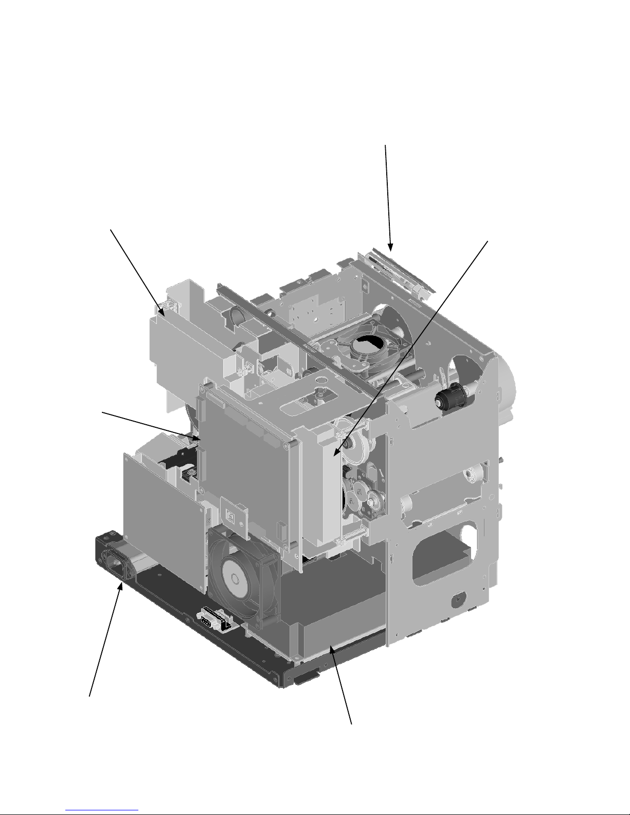
2. REAR: MOTOR, FAN AND SENSORS
Card Feed Motor in Turnover Unit
Head Press Cam Position Detection Sensor
Card Turnover Motor Ink Ribbon FG Sensor
Head Press Cam Motor
Ink Ribbon
Winding Motor
Card Feed Motor
Rear Fan
Card Supply Motor
MG / IC Unit (Optional)
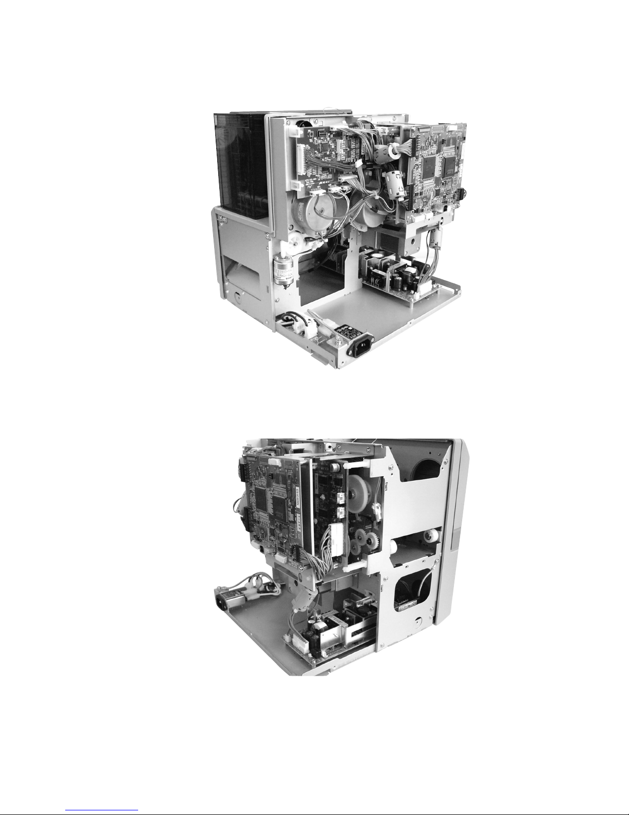
LAYOUT OF KEY PARTS
6
3. BOARDS AND POWER SOURCES
Front Board
DAD Board
Drive Board
Main Board
AC Inlet
Power Supply Unit
LAYOUT OF KEY PARTS
7
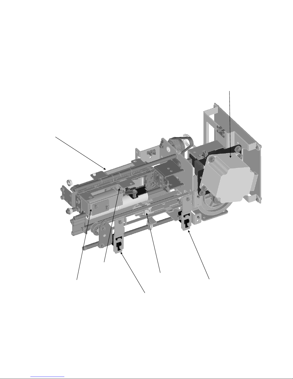
4. MG / IC UNIT
MG Head Carriage Motor
IC Contact
(ISO MG Type)
IC Contact
(JIS MG Type)
MG Head Assembly
IC Contact Pressure Solenoid (JIS MG Type)
MG Head Origin Sensor (For ISO)
MG Head Origin Sensor (For JIS)
8
DISMANTLING KEY PARTS
13
8
4
1
(TFA0022)
13
KJJ46271-003x4
14
KJJ46271-003
QYSPSPH3006N
QYSDSP3006N
x 2
8
QYSDSP4008N
Loosen the screws
8
Loosen the screws
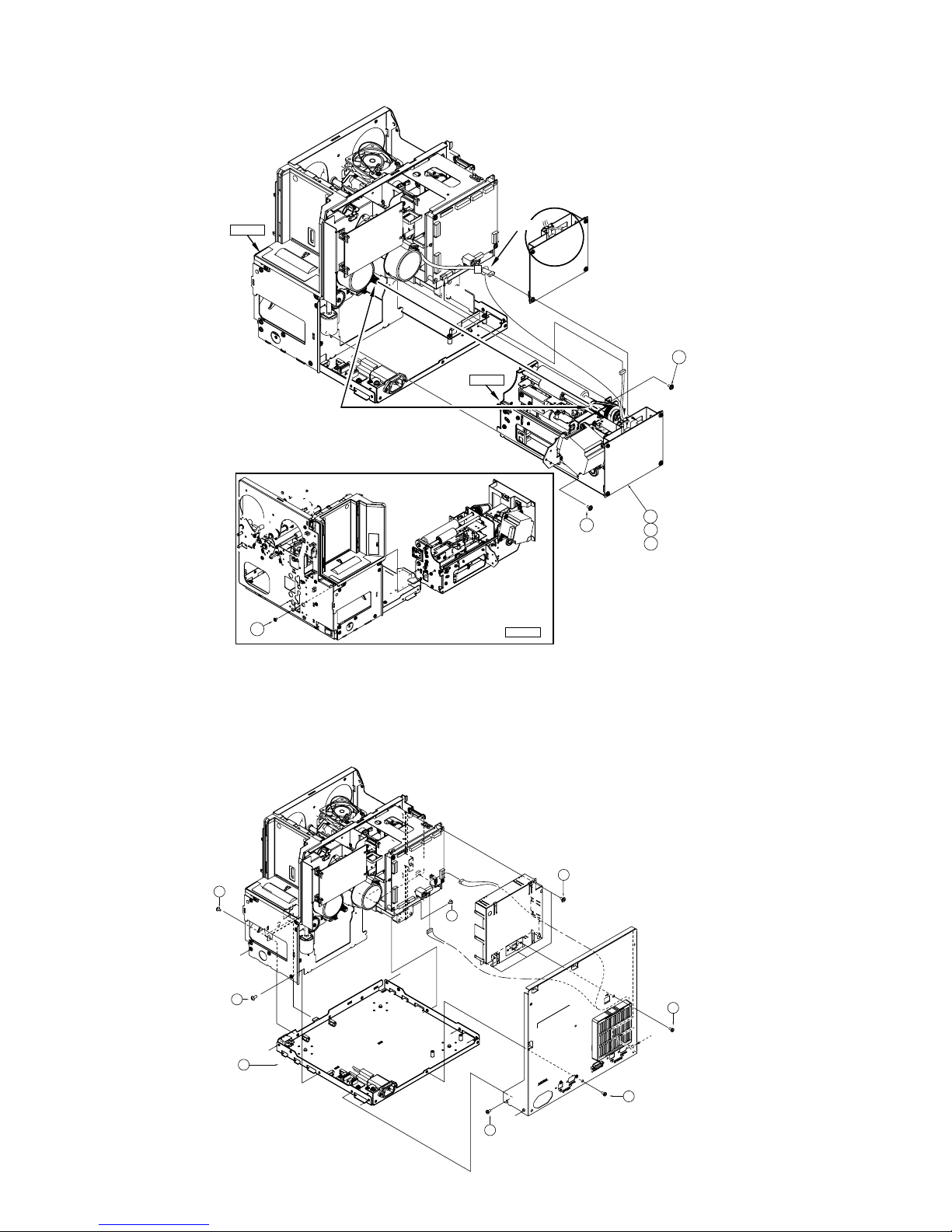
1. LAYOUT DIAGRAM DURING MAINTENANC
DISMANTLING KEY PARTS
The rear panel can be opened for maintenance by removing the following screws.
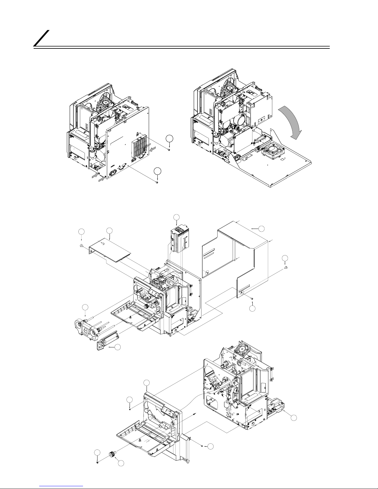
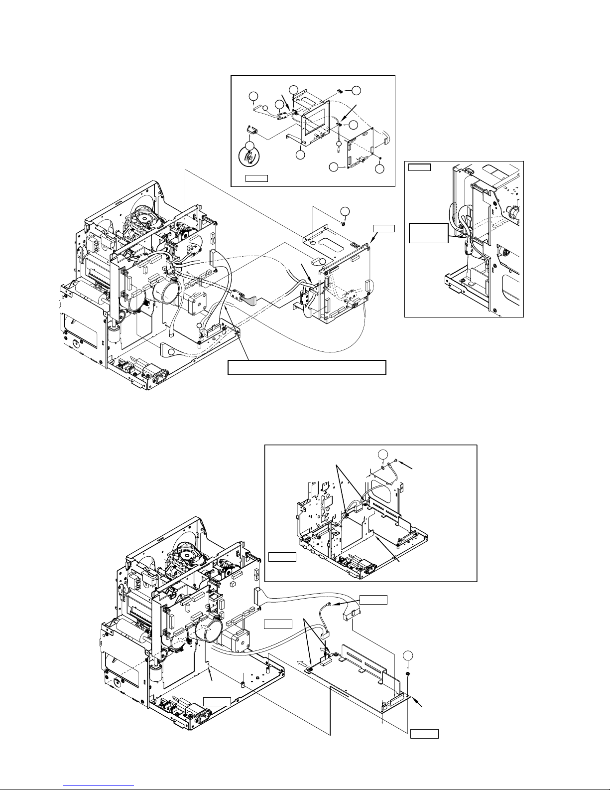
2.
DISMANTLING EXTERNAL PARTS AND REFERENCE WIRING DIAGRAM
2.1 Dismantling the Top Cover
2.2 Dismantling the Front Panel
12
KJJ46697-001x2
QYSDSP4008Nx2
13
5
1
3
13
6
QYSDSP
4008N x4
2
9
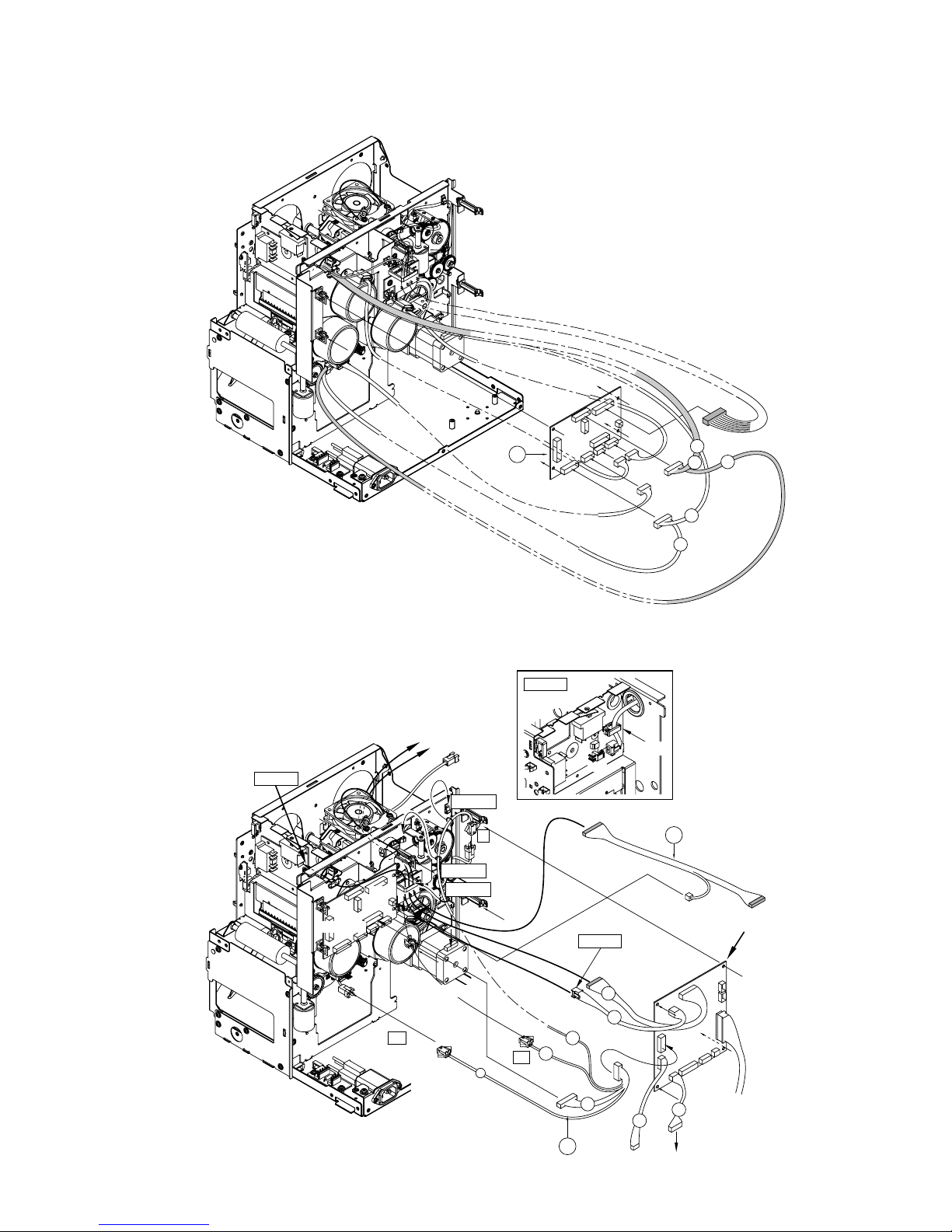
DISMANTLING KEY PARTS
2.3 Reference Wiring Diagram
10
DISMANTLING KEY PARTS
3. DISMANTLING THE MG / IC UNIT
4. SEPARATING THE CHASSIS AND MECHANICAL UNIT AND DISMANTLING BOARDS
4.1 Dismantling the Chassis, Mechanical Unit and Rear Panel
QYSPSPH
3006Nx2
9
QYSPSPH3006N x2
QYSPSPH3006N
Figure 1
Figure 1
Figure 1
MG/IC
To J3
CN8
9
9
G.No.004
3
G.No.003
2
G.No.002
1
(MAIN)
Hang belt on the gear.
Front Screw Fitting
Front Screw Fitting
Front Screw Fitting
Clamp
MAIN
To CN8
J3
(MG/IC)
Gr
Be careful not
to catch the
wires when
assembling.
16
KJJ46271-003x2
3
16
KJJ46271
-003x2
16
KJJ46271
-003x2
CN5
KJJ46271-003x3
7
CN32
8
KJJ46271-003x4
7
QYSDSP4008N
8
QYSDSP4008N
11
DISMANTLING KEY PARTS
4.2 Dismantling Boards and Power Supply Units
4.2.1 Dismantling the DAD Board
4.2.2 Dismantling the Drive Board
3
(TPS239-1)
DAD PWB
CN72
CN71
CN78
CN77
CN79
8p
6p
7p
5p
Br
CN73
10p
R
Or
Br
R
Clamp
Clamp
To CN74
of DAD PWB
CN74
DAD PWB
Connect to CN93 of
the Interlock PWB
KWS0728-001
5
DRIVE PWB SA
Clamp
Clamp
Figure 2
Figure 2
Figure 2
HF
CN76
IN
HO
KWS0733-001
8
INTERLOCK PWB
Card Feed Motor
CN93
CN24
Card Feed Motor
CN76
BL
Wh
GR
R
Y
OR
R
BR
To CN93
12
DISMANTLING KEY PARTS
4.2.3 Dismantling the Main Board
4.2.4 Dismantling the Power Circuit Board
Insert power
supply wiring
into the clamp
Wiring at
PWB BKT’s End
14
12
3
13
12
9
QYSPSPH
3006N x3
MAIN PWB
(TPS237-1)
Figure 2
Figure 1
2
KWS0729-001
CN6
PWB BKT SA
1
Clamp
Clamp
R
7
OR
CN7
OR
OR
KJJ46271-003x4
CN7
CN4
CN21
CN21
PWB BKT SA
Clamp
Insert red wire by guiding it from the rear of CN2
(Adjust accordingly such that the red wire does not protrude from behind)
CN2
R
CN70
10
CN70
Figure 2
7
QYSPSPH
3006N x2
Insert into the slit
at the bottom
POWER SUPPLY SA
Installing the
Power Source and Wiring
Clamp the power
circuit board
10
QYWBS326505N
Installing the
Power Source and Wiring
Remove screws on
the frame to fasten
the FG wires together.
Clamp the power
circuit board
Insert into the slit at the bottom
Figure 2
Figure 2
Figure 2
Figure 2
Figure 2
13
DISMANTLING KEY PARTS
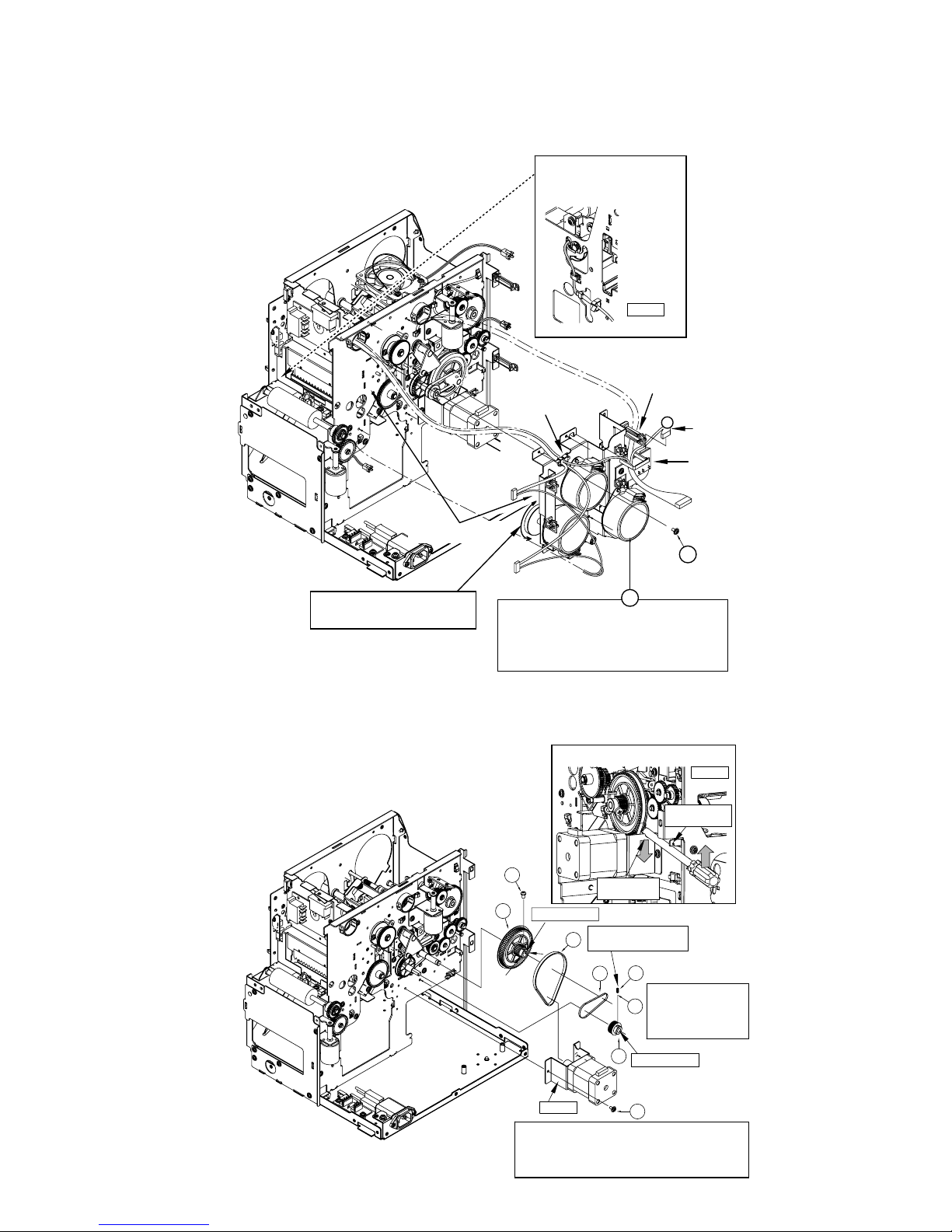
5. DISMANTLING THE MOTOR ASSEMBLY
5.1 Dismantling the Turn Motor Assembly
5.2 Dismantling the Stepping Motor Assembly
1
5
KJJ46271
-003 x5
(TSS0233)
Clamp
Insert the
connector
Lead the wire from underneath
the card edge holder
[Before Installation]
• Check wiring (See Figure 1)
• Adjust position of wire of the turnover unit (See Figure 2)
• Check cam position (See Figure 3)
[During Installation]
• Ensure that wires are not trapped in the shaft
• Ensure that wires are not caught
Before installing the turn motor unit,
turn the turnover unit and ensure that
the wire is located on the left as
shown in the diagram.
Figure 2
Clamp the wire that is
guided through the bush
R
Be careful not to
catch the wires
Upon installing the turn motor assembly,
check by turning the jog dial to ensure
that the turnover unit rotates.
4
5
6
7
19
KJJ46271-003 x2
21
QYYASPW4006F
22
Lock the screws upon
fastening.
Perform secondary
tightening on the screws
(torque: 1.96 - 2.35 N.m)
23
QYSPSP
4008N x3
(126)
Shaft and Face 1
Shaft and Face 1
Fasten screws on the flat
surface of the shaft
STEPPING MOTOR SA
[Procedures for Fastening Screws on the Stepping Motor]
1) Tighten the screws temporarily to the main unit, and
tighten using a driver as shown in Figure 3.
2) After tension is properly adjusted, tighten the screws fully.
Hang the driver
on the notch
Use BKT as the
point of support
Figure 3
Figure 1
Tightening the Belt
14
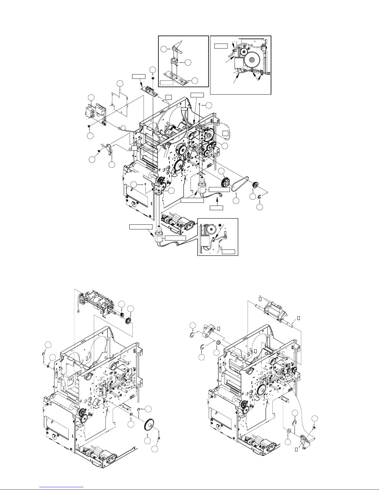
DISMANTLING KEY PARTS
6.
DISMANTLING THE TURNOVER UNIT
7. DISMANTLING THE HEAD
PRESS ASSEMBLY
CL SENSOR
(KEP4103-Q)
CN99
CN82
20
6
20
KJJ46271-003
NC
CL
P
KJJ46271-003
Labeled Face
Labeled Face
Clamp
21
QYSPSPL
3004N x2
21
QYSPSPL
3004N x2
FG
CX-120-M04
3
3
9
20
INTERLOCK PWB
CN94
(KEP4103-N)
12
13
14
19
(184)
QYREE4000X
Figure 2
Figure 2
NC SENSOR PWB
(KEP4103-D)
6
7
8
Insert both ends firmly
Insert
6
KJJ46271-003x2
CX-120-M04
Clamp
Clamp
Ensure that the wire is not
in contact with the spring
Ensure that the
wire is not in
contact with
the gear
Figure 4
Figure 4
Figure 4
Figure 5
13
18
QYREE
5000X
QYREE
5000X
13
11
12
x2
18
15
17
QYREE4000X
20
28
20
A
A
28
B
B
QYREE7000X
QYREE7000X
QYREE
7000X
28
B
18
QYSPSPH4008N
5.3 Dismantling the DC Motor
15
MECHANICAL OPERATIONS
Operations of the card printer mechanism can be divided into 5 types, namely initialize operation, feed operation,
print operation, MG operation and IC operation. Commands from the host are made up using a combination of
these operations. For example, the actual print command is realized via the serial execution of a feed operation
from the hopper to the print position and a print operation. As an illustration, please refer to the sequence diagram
for each item, which describes operations required for duplex printing (paper feed, print, turnover and discharge).
1. INITIALIZE OPERATION
Upon turning on the power, perform the following steps to initialize the mechanism.
1) Initialize MG head position
2) Raise the thermal head
3) Load the ink ribbon to the ready position (when head is lowered or when using a new ink ribbon)
4) Check for any cards remaining in the card feed unit and discharge accordingly (NG Exit)
5) Check for any cards remaining in the MG unit and discharge accordingly (NG Exit)
2. FEED OPERATION
The feed operation is used to transfer a card to a specific position, and it is possible to add an optional turnover
operation. The feed unit is divided into 2 blocks, made up by a card feed motor inside the turnover unit and another
card feed motor. Feeding in the MG unit is performed using the card feed motor inside the turnover unit.
Card discharge from the print position and Card feed operation to a print position are illustrated in a sequence
diagram. In the sequence diagram, the direction of motor operation from right to left (top to bottom in the case of the
MG unit) when viewed from the front is indicated as FWD.
Feed Destinations
There are 6 feed destinations as indicated below.
MECHANICAL OPERATIONS
1
Stop
Inside Hopper
3
Stop
Print Position
2
Feeding
to Print
Position
Hopper
Print
Position
Operation Card
Position
Card Feed
Motor
Print Position
Sensor for
Card
FWD REV
Passed Blocked
Card Feed → Print Position
Card Feed
Motor in
Turnover Unit
Card Sensor
in Turnover
Unit
FWD REV
Passed Blocked
Card Supply
Motor
FWD REV
1
Stop
Print Position
3
Stop No Card
2
Discharging
Print Position
→
Discharge
Operation
Card
Position
Card Feed
Motor
Card Discharge
Sensor
FWD REV
Passed Blocked
Discharging from the Print Position
Print Position Non-contact IC Position
MG Position Card Exit
IC Position NG Card Exit
 Loading...