

DNP CL-500 Service Manual
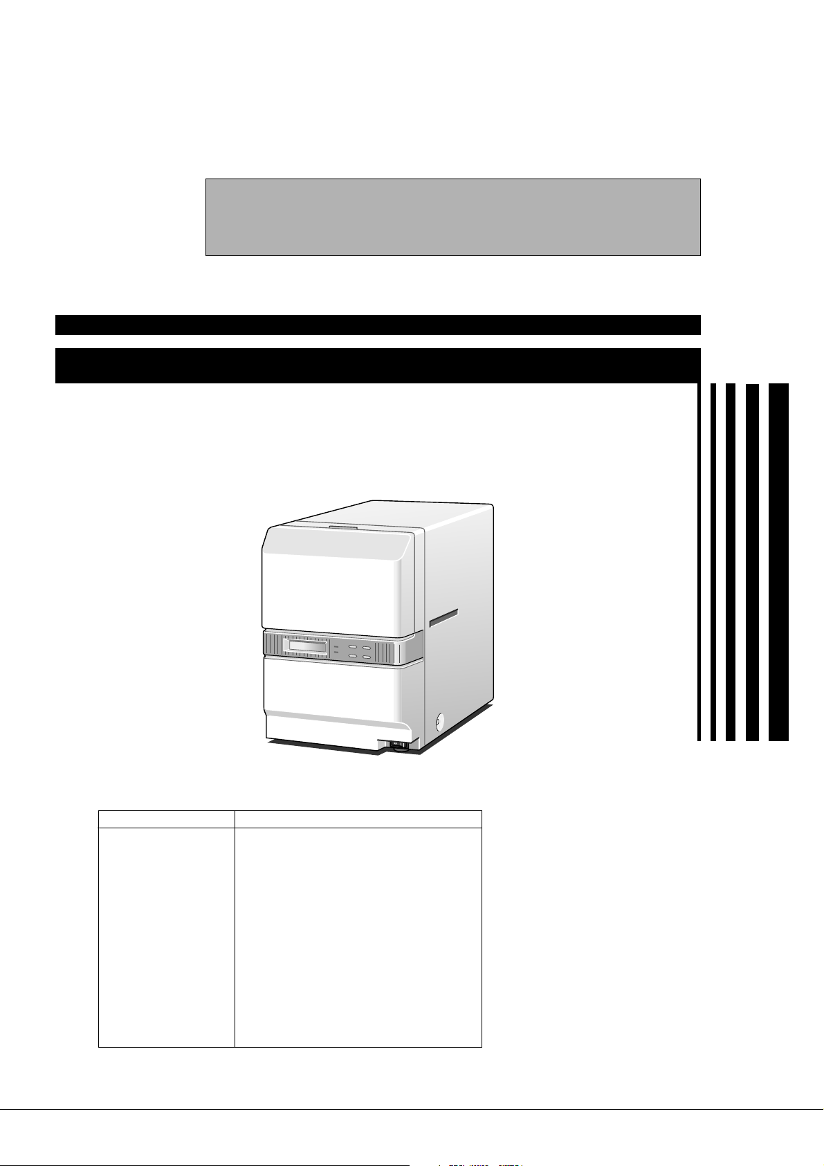
DNP
LAMINATOR FOR CARD PRINTER
SERVICE MANUAL
CL-500
SPECIFICATIONS
Item Content
Transfer method Halogen lamp built-in heat roller method
Transfer time Approx. 20 seconds
Usage environment Temperature 15°C - 30°C
Storage environment
Power supply AC 100 V - 120 V (tolerance ±10%)
Power consumption Approx. 200 W
Unit mass Approx. 9 kg
Compatible specification
Accessories Power cord x 2 (for Europe and US market)
Option Cleaning card set x 1 [10p/set (CX210-CC1)]
Changes may be made to the specifications and external appearance of this machine for product improvement
without prior notice.
The time varies according to settings.
Humidity 30 % - 70% (without condensation)
Temperature –15°C - 55°C
Humidity 20 % - 80%
VCCI-B
Instructions
Unit joining plate
Cleaning card x 1
KAS-T078-005
July 2007

CONTENTS
IMPORTANT SAFETY PRECAUTIONS
MODEL NAME ................................................................................. 1
1. DETAILED SPECIFICATION ....................................................... 1
SCHEMATIC DIAGRAM ..........................................................2
MAIN COMPONENTS LAYOUT DIAGRAM ............................... 3
1. FRONT: HEAT ROLLER, TRANSPORT ROLLER AND
SENSORS ...................................................................................3
2. REAR: MOTOR, FAN, SENSORS AND SWITCHES ..................4
3. VARIOUS CIRCUIT BOARDS AND POWER SUPPLY ...............5
REMOVING MAIN PARTS ............................................................ 6
1. REPLACING HEATER ................................................................ 6
2. REMOVING EXTERNAL PARTS AND WIRING
REFERENCE DIAGRAM ............................................................ 6
2.1 REMOVING COVER ............................................................. 6
2.2 REMOVING FRONT PANEL .................................................6
2.3 WIRING REFERENCE DIAGRAM ........................................ 7
3. REMOVING MAIN PA RTS .......................................................... 9
3.1 SEPARATING CHASSIS AND MECHANICAL UNIT .............9
3.1.1 Removing Power Supply and Main Board ...................... 9
3.1.2 Separating Chassis and Mechanical Unit ....................... 9
3.2. REMOVING MECHANICAL MAIN PA RTS ......................... 10
3.2.1 Removing Feed Motor .................................................. 10
3.2.2 Removing Heater Unit and Heater ASSY ..................... 10
3.2.3 Removing Heat Roller .................................................. 11
3.2.4 Removing Transport Roller ........................................... 11
ASSEMBLY DIAGRAM AND PARTS TABLE ............................33
IMPORTANT .............................................................................33
MECH ASSY (PLATE R ASSY) ................................................34
MECH ASSY (CENTER FRAME ASSY) .................................. 35
MECH ASSY ............................................................................ 36
CARD GUIDE IN ASSY ............................................................37
CARD GUIDE OUT ASSY ........................................................38
MEDIA T UP MOTOR ASSY .....................................................39
HEATER MOTOR ASSY ...........................................................40
HEATER ASSY .........................................................................41
HEATER UNIT .......................................................................... 42
FEED MOTOR ASSY ............................................................... 43
FEED ROLLER ASSY .............................................................. 44
AC BLOCK ASSY .....................................................................45
BOTTOM ASSY ........................................................................ 46
MECH FRAME ASSY ...............................................................47
FRONT PANEL ASSY (FRONT) ...............................................50
FRONT PANEL ASSY (REAR) .................................................51
FINAL ASSY (PANEL) .............................................................. 52
FINAL ASSY (REAR) ............................................................... 53
ANNEX ASSY ........................................................................... 54
FINAL (PACKING) ASSY .......................................................... 55
USING SERVICE MODE .............................................................12
1. USER MODE ............................................................................ 12
2. SERVICE MODE ....................................................................... 13
3. FIRMWARE UPDATE ................................................................ 14
MECHANISM OPERATION ......................................................... 17
1. INITIAL OPERATION ................................................................ 17
2. LAMINATING OPERATION ....................................................... 17
TROUBLESHOOTING..................................................................19
1. HANDLING ERROR CODES ....................................................19
2. HANDLING CARD JAM............................................................. 22
3. HANDLING THE SITUATION WHERE POWER SUPPLY
IS CUT OFF WHEN THE HEAT ROLLER IS DOWN ................ 24
SET UP GUIDE ............................................................................. 25
1. SETTING OF LAMINATE CONDITION .....................................25
2. SETTING PROCESS ................................................................ 27
3. VARIOUS CONDITIONAL SETTINGS ......................................28
4. CARD ADHESIVENESS ........................................................... 30
MAINTENANCE ............................................................................. 31
1. CLEANING ................................................................................ 31
2. LIST OF PARTS TO BE REPLACED.........................................31
ADJUSTMENT ............................................................................... 32
1. ARRANGEMENT OF ADJUSTMENT VOLUME ....................... 32
2. HOW TO ADJUST THE VOLUME ............................................. 32
SAFETY PRECAUTION
1.25
2.0
5.5
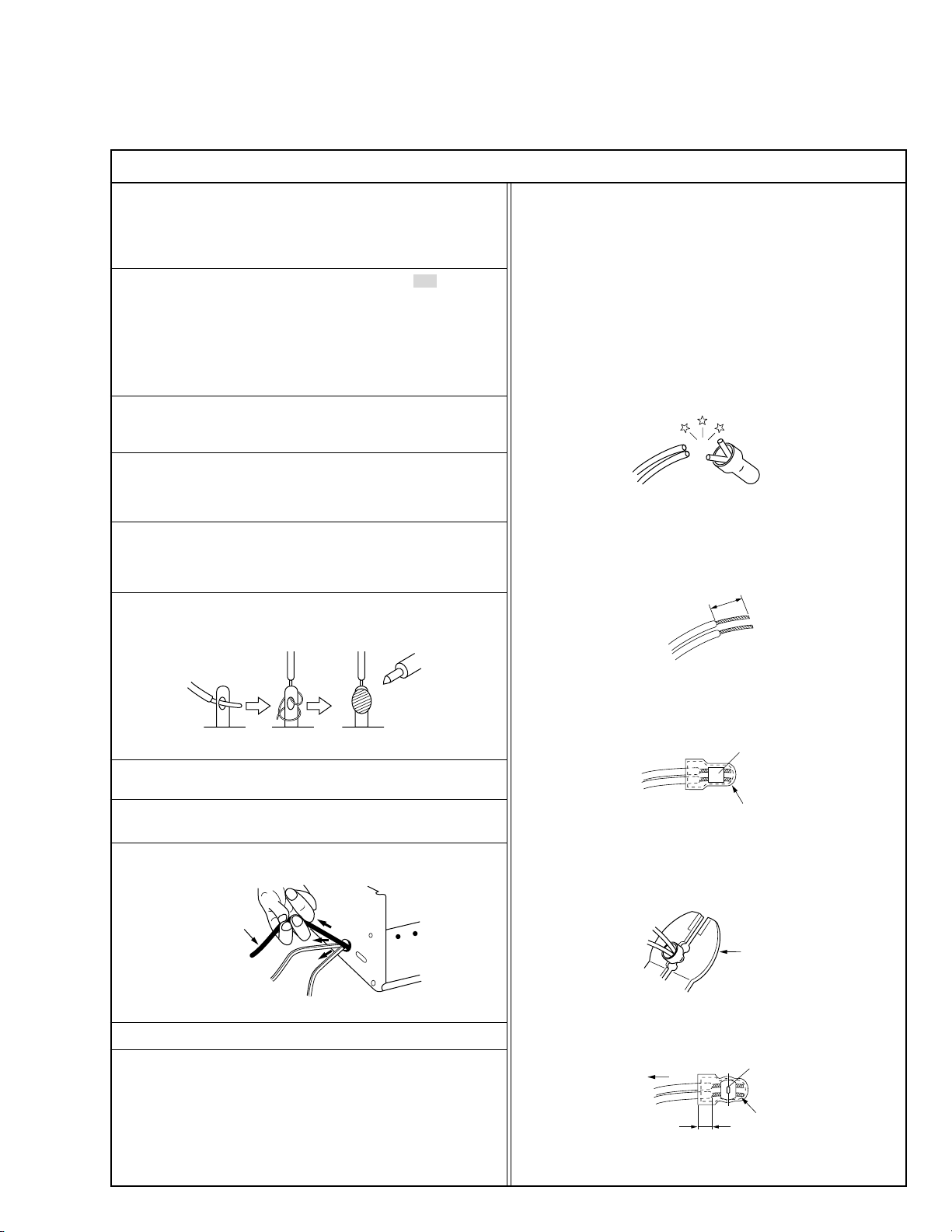
Crimping tool
Important Safety Precautions
Prior to shipment from the factory, JVC products are strictly inspected to conform with the recognized product safety and electrical codes of the
countries in which they are to be sold. However, in order to maintain such compliance, it is equally important to implement the following precautions
when a set is being serviced.
Precautions during Servicing
•
1. Locations requiring special caution are denoted by labels and inscriptions on the cabinet, chassis and certain parts of the product.
When performing service, be sure to read and comply with these
and other cautionary notices appearing in the operation and service manuals.
2. Parts identified by the
critical for safety.
Replace only with specified part numbers.
Note: Parts in this category also include those specified to comply
with X-ray emission standards for products using cathode ray
tubes and those specified for compliance with various regulations regarding spurious radiation emission
.
3. Fuse replacement caution notice.
Caution for continued protection against fire hazard.
Replace only with same type and rated fuse(s) as specified.
4. Use specified internal wiring. Note especially:
1) Wires covered with PVC tubing
2) Double insulated wires
3) High voltage leads
5. Use specified insulating materials for hazardous live parts. Note
especially:
1) Insulation Tape 3) Spacers 5) Barrier
2) PVC tubing 4) Insulation sheets for transistors
6. When replacing AC primary side components (transformers, power
cords, noise blocking capacitors, etc.) wrap ends of wires securely
about the terminals before soldering.
! symbol and shaded ( ) parts are
12. Crimp type wire connector
In such cases as when replacing the power transformer in sets
where the connections between the power cord and power transformer primary lead wires are performed using crimp type connectors, if replacing the connectors is unavoidable, in order to prevent
safety hazards, perform carefully and precisely according to the
following steps.
1) Connector part number : E03830-001
2) Required tool : Connector crimping tool of the proper type which
will not damage insulated parts.
3) Replacement procedure
(1) Remove the old connector by cutting the wires at a point
close to the connector.
Important : Do not reuse a connector (discard it).
cut close to connector
Fig.3
(2) Strip about 15 mm of the insulation from the ends of the
wires. If the wires are stranded, twist the strands to avoid
frayed conductors.
15 mm
Fig.4
(3) Align the lengths of the wires to be connected. Insert the
wires fully into the connector.
Fig.1
7. Observe that wires do not contact heat producing parts (heatsinks,
oxide metal film resistors, fusible resistors, etc.)
8. Check that replaced wires do not contact sharp edged or pointed
parts.
9. When a power cord has been replaced, check that 10-15 kg of
force in any direction will not loosen it.
Power cord
Fig.2
10. Also check areas surrounding repaired locations.
11. Products using cathode ray tubes (CRTs)
In regard to such products, the cathode ray tubes themselves, the
high voltage circuits, and related circuits are specified for compliance with recognized codes pertaining to X-ray emission.
Consequently, when servicing these products, replace the cathode ray tubes and other parts with only the specified parts. Under
no circumstances attempt to modify these circuits.
Unauthorized modification can increase the high voltage value and
cause X-ray emission from the cathode ray tube.
I
(4) As shown in Fig.6, use the crimping tool to crimp the metal
sleeve at the center position. Be sure to crimp fully to the
complete closure of the tool.
(5) Check the four points noted in Fig.7.
Not easily pulled free
Wire insulation recessed
more than 4 mm
Metal sleeve
Connector
Fig.5
Fig.6
Crimped at approx. center
of metal sleeve
Conductors extended
Fig.7
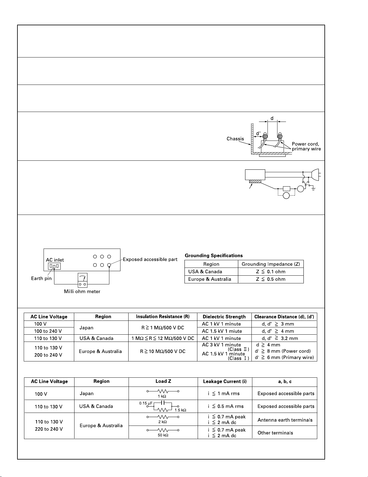
SAFETY PRECAUTION
Safety Check after Servicing
•
Examine the area surrounding the repaired location for damage or deterioration. Observe that screws, parts and wires have been returned
to original positions, Afterwards, perform the following tests and confirm the specified values in order to verify compliance with safety
standards.
1. Insulation resistance test
Confirm the specified insulation resistance or greater between power cord plug prongs and externally exposed parts of the set (RF terminals, antenna terminals, video and audio input and output
terminals, microphone jacks, earphone jacks, etc.). See table 1 below.
2. Dielectric strength test
Confirm specified dielectric strength or greater between power cord plug prongs and exposed accessible parts of the set (RF terminals, antenna terminals, video and audio input and output terminals,
microphone jacks, earphone jacks, etc.). See table 1 below.
3. Clearance distance
When replacing primary circuit components, confirm specified clearance distance (d), (d’) between soldered terminals, and between terminals and surrounding metallic parts. See table 1
below.
Fig. 8
4. Leakage current test
Confirm specified or lower leakage current between earth ground/power cord plug prongs and
externally exposed accessible parts (RF terminals, antenna terminals, video and audio input and
output terminals, microphone jacks, earphone jacks, etc.).
Measuring Method : (Power ON)
Insert load Z between earth ground/power cord plug prongs and externally exposed accessible
parts. Use an AC voltmeter to measure across both terminals of load Z. See figure 9 and following
table 2.
Externally
exposed
accessible part
Z
V
Fig. 9
ab
c
A
5. Grounding (Class 1 model only)
Confirm specified or lower grounding impedance between earth pin in AC inlet and externally exposed accessible parts (Video in, Video out,
Audio in, Audio out or Fixing screw etc.).
Measuring Method:
Connect milli ohm meter between earth pin in AC inlet and exposed accessible parts. See figure 10 and grounding specifications.
Fig. 10
Tab le 1 Specifications for each region
Table 2 Leakage current specifications for each region
Note: These tables are unofficial and for reference only. Be sure to confirm the precise values for your particular country and locality.
II

MODEL NAME
Alphabets and numbers after the model name indicate the different destinations and specifications.
ID label display: CL-500*1-DN
1. DETAILED SPECIFICATION
*1 : Destination
None : For Japan (100 V specification)
U:For North America (100 V – 120 V specification)
E:For Europe (100 V – 120 V specification) (220 V – 240 V specification)
MODEL NAME
1
SCHEMATIC DIAGRAM
SCHEMATIC DIAGRAM
AC 100 V/200 V switching model
Card insert detection
sensor (Board)
Laminate position
sensor (Board)
Card ejecting sensor
(Board)
Film (Black)
Mark sensor end
Mark sensor
Thermistor (Board)
°
C
CN5
CN11
CN10
External machine
IF connector
Printer IF connector
Interlock switch
When the interlock switch is turned off
(cassette is removed), the 24 V power
supply for the motor is switched off, all
motor stops and the heater is turned off.
Film FG sensor
(Board)
Heat roller pressure
position sensor (HR2)
Heat roller standby
position sensor (HR1)
Card transport
motor
Film reeling
motor
Heater
cam motor
Back fan motor
Card cooling
fan motor
Front panel
KEP3160-B
FRONT PWB
Relay connector
CN1
CN3
CN2
CN4
CN9
KEP3160-A
MAIN PWB
CN13
CN12
CN8
CN6
Interlock switch
(Cassette switch)
Powe r
supply
Relay connector
Tr ansformer
*1
CN3
CN2
CN6
CN5
Halogen heater
°
C
Thermostat
*1 Not available for AC 100 V model
*2 Not available for AC 100 V model
*3 Not available for AC 100 V model
*2
100 V/200 V
AC selector switch (Board)
AC inlet
CN601
CN7
KEP4101-A
AC PWB
CN4
CN8
CN9
CN1
Power switch
KEP4101-F
PROTECT PWB
*3
CN501
CN502
2
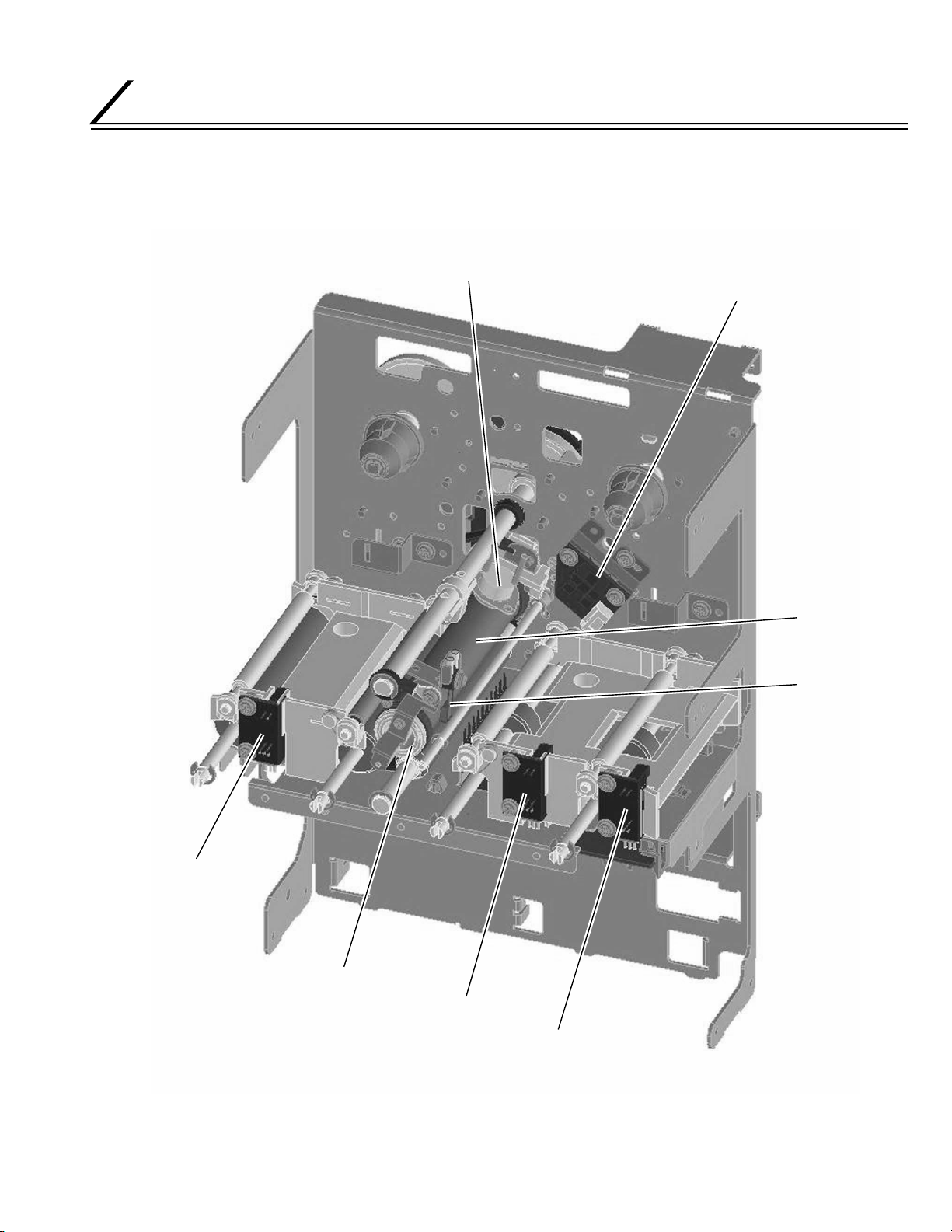
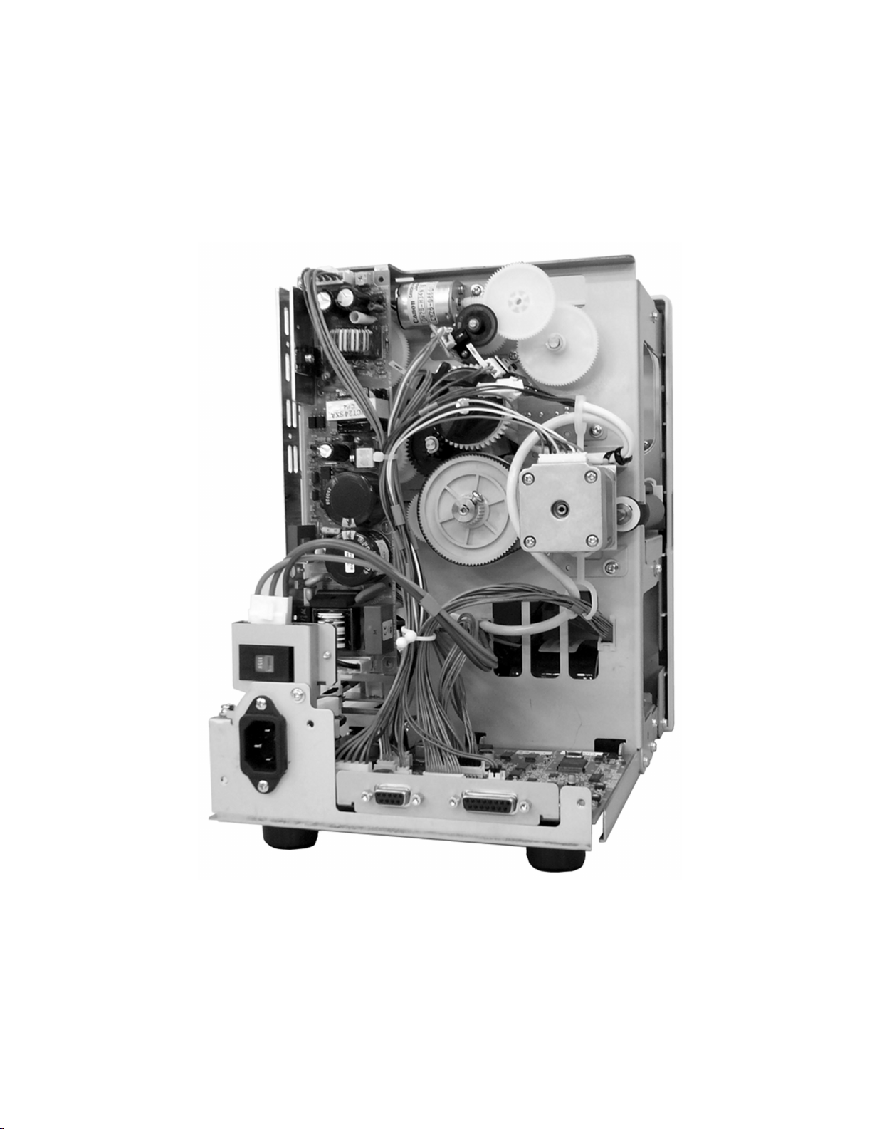
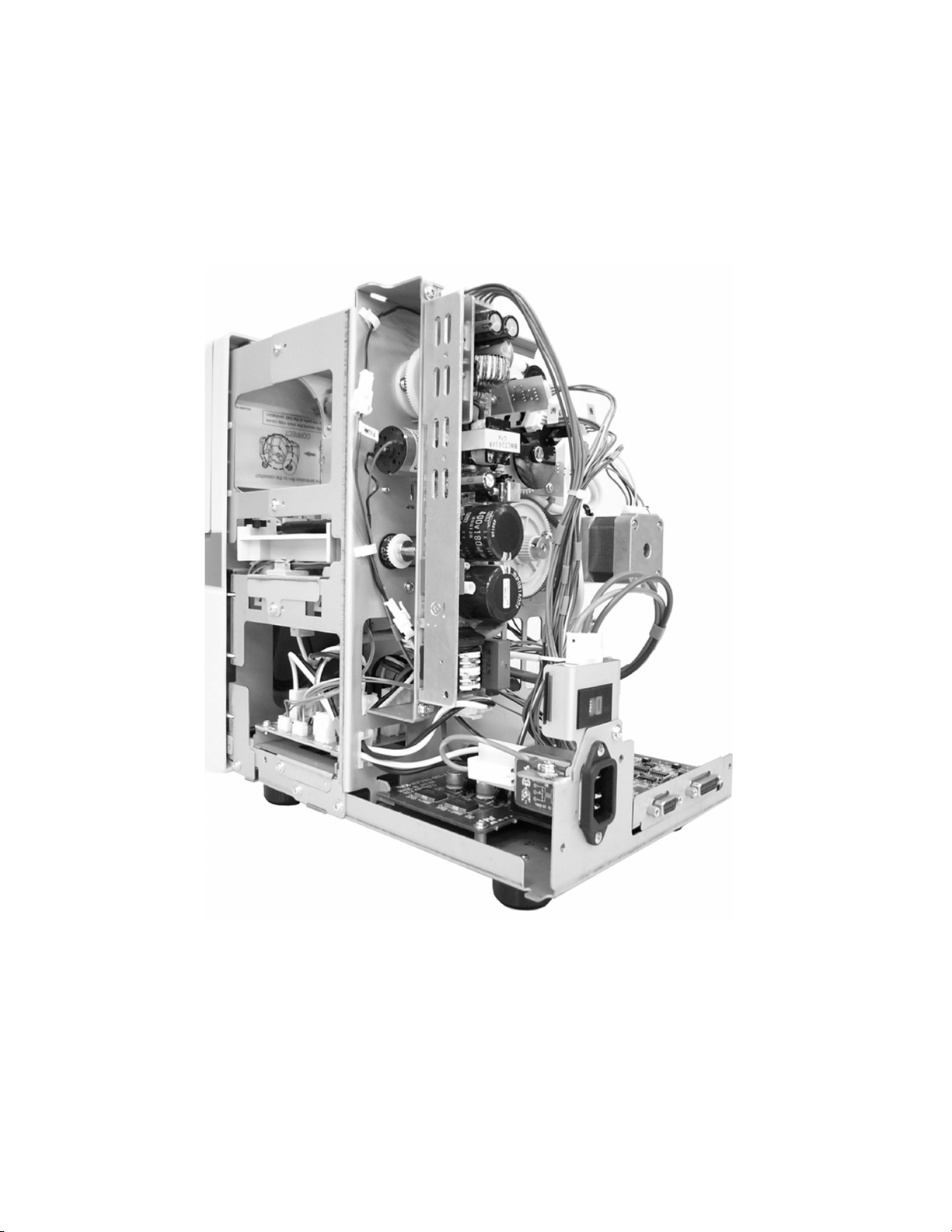
MAIN COMPONENTS LAYOUT DIAGRAM
Card ejecting sensor
Thermostat
Heat roller
Film mark sensor and
end mark sensor
Thermistor
Halogen heater
Laminate position sensor
Card insert detection sensor
MAIN COMPONENTS LAYOUT DIAGRAM
1. FRONT : HEAT ROLLER, TRANSPORT ROLLER AND SENSORS
3
MAIN COMPONENTS LAYOUT DIAGRAM
2. REAR : MOTOR, FAN, SENSORS AND SWITCHES
Film reeling motor
Cassette interlock SW
Heater cam motor
Film FG sensor
Heat roller
pressure position sensor
Heat roller
standby position sensor
AC select switch
Card cooling fan
Card transport motor
Back fan
4
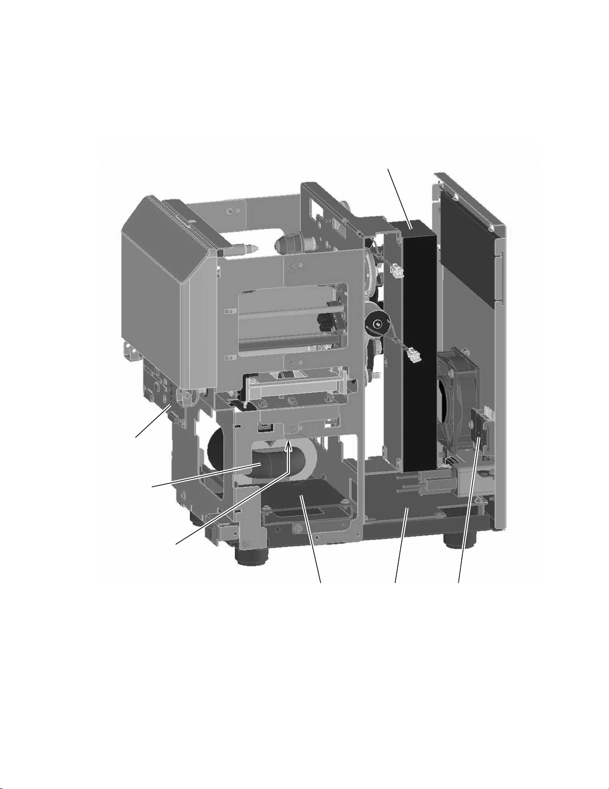
MAIN COMPONENTS LAYOUT DIAGRAM
3. VARIOUS CIRCUIT BOARDS AND POWER SUPPLY
Power unit
Front board
Transformer
Protective board
AC board
Main board AC select SW board
5
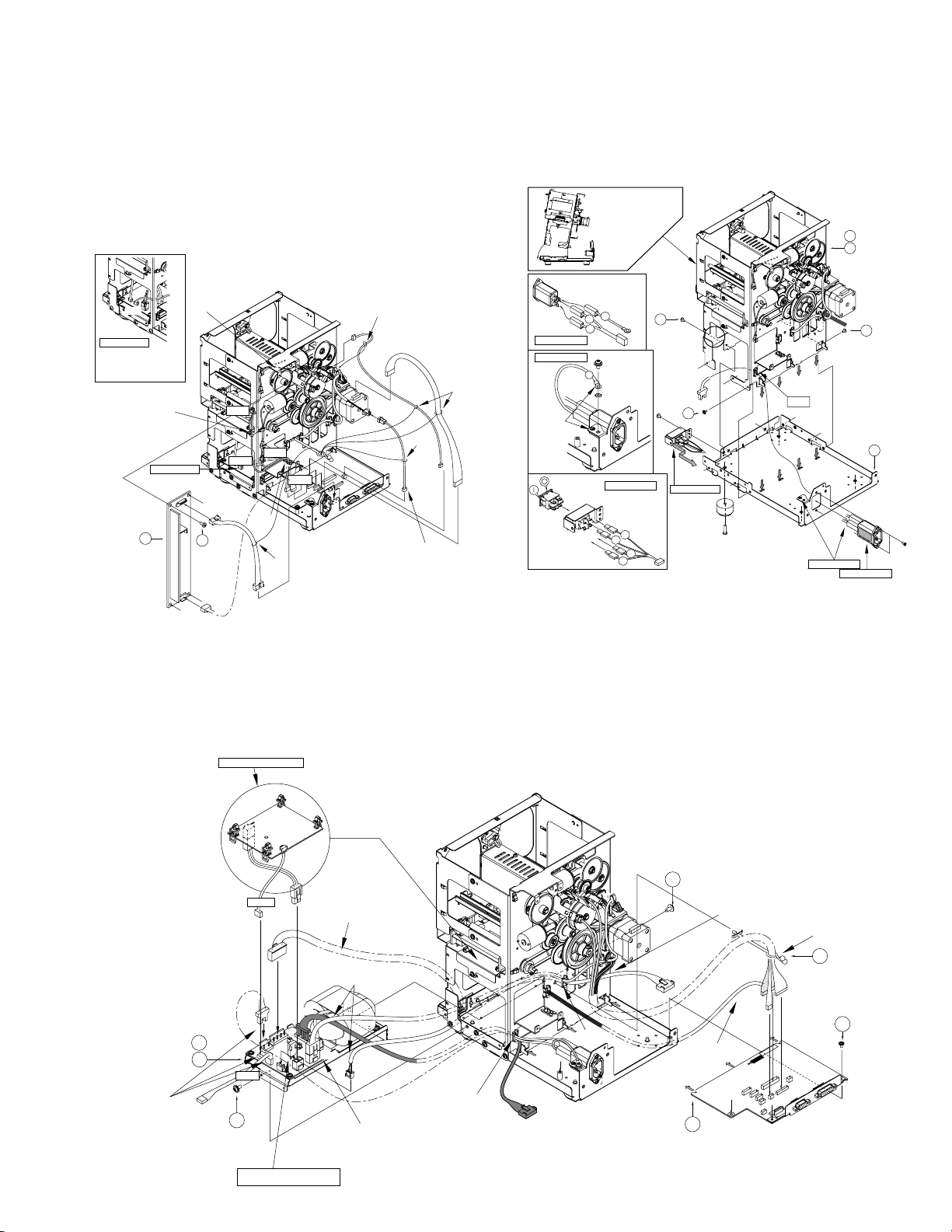
REMOVING MAIN PARTS
REMOVING MAIN PARTS
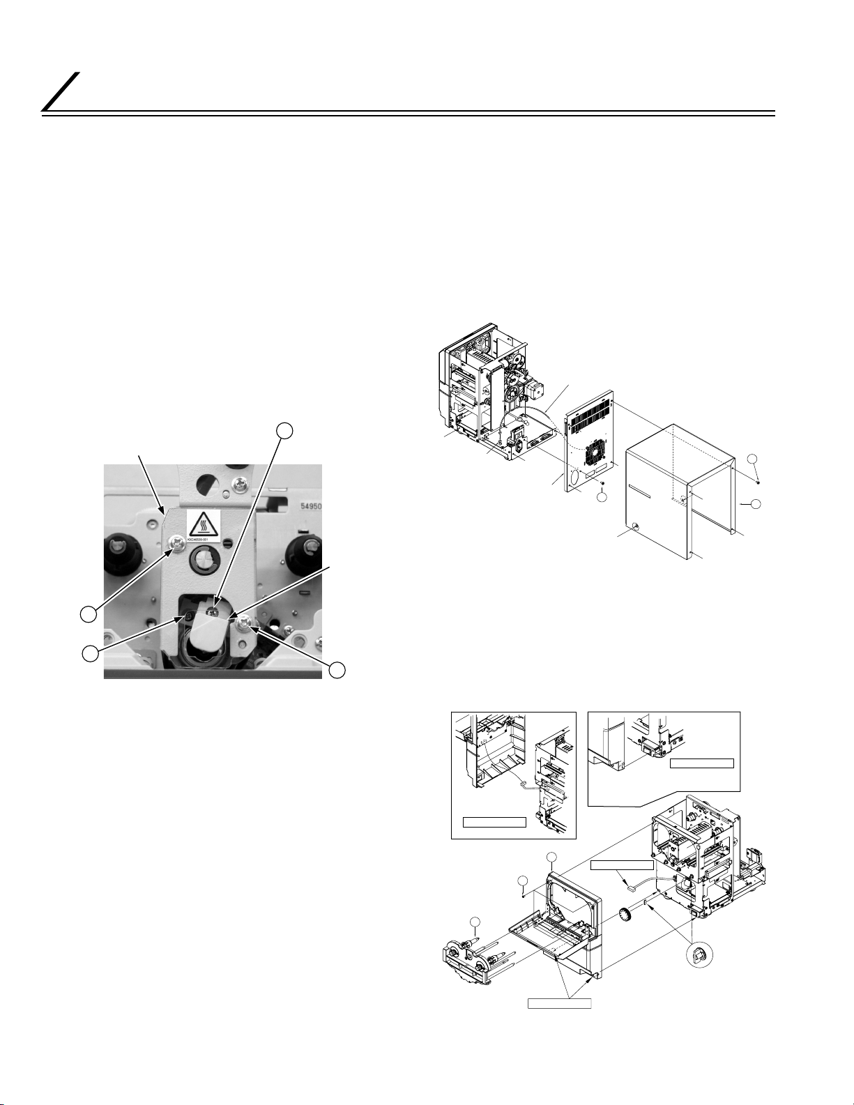
1. REPLACING HEATER
1) Remove two screws
sheet.
2) Remove one screw
and remove the hook on the inner right hand side to
remove the halogen lamp.
Important : Do not remove screw Ç as this will break
the contact point of the heater.
3) Pull the halogen heater out to the front, replace it
with a new halogen heater and attach the screws in
the reverse order.
Important : Do not touch the glass section of the halo-
gen heater. Oil secretion from your hand
may reduce the lamp life.
Protective sheet
and remove the protective
Å
, shift the connect base a little
ı
C
Screw
(Do not remove)
2. REMOVING EXTERNAL PARTS
AND WIRING REFERENCE
DIAGRAM
2.1 REMOVING COVER
1) Remove six screws
2) Pull the fan cable from the main board and remove
screw
and the rear panel.
ı
CN2
Rear panel
and remove the top cover !.
Å
Fan cable
B
QYSDSP
4008N
QYSDSP4008N
x6
A
11
Screw
Screw
Connect
base
A
2.2 REMOVING FRONT PANEL
B
A
Screw
1) Remove cassette 5 and remove four screws Å.
2) Remove the front panel
slightly and pull the con-
4
nector on the front board.
CN02
Inset Diagram 2
Insert to FRONT
board CN02
Inset Diagram 1
(TFS0125)
QYSDSP3006Nx4
(TFS0126)
5
Insert the claws on both sides of the
front panel to the plate and fasten
with screws.
4
A
Inset Diagram 1
Connector
Insert to shaft
Inset Diagram 2
Important
• Screws should be tightened.
• Do not wedge the wire into sharp edges.
6
2.3 WIRING REFERENCE DIAGRAM
1) Refer to this photograph and each assembly diagram to organize the wiring.
REMOVING MAIN PARTS
7
REMOVING MAIN PARTS
8
REMOVING MAIN PARTS
3. REMOVING MAIN PARTS
3.1 SEPARATING CHASSIS AND MECHANICAL UNIT
3.1.1 Removing Power Supply and Main Board
1) Demount the connector, remove four screws Å and
pull out the power supply 8.
Motor wires should not
Clamp
Inset Diagram 1
touch the gears
CN201
A
KJJ46271
-003 x4
FILMM
Yellow
CN6
Clamp
CAMM
Clamp
CN3
Yellow
CN8
Clamp
Clamp
CN13
CN6
Connector black
CN6
Inset Diagram 1
Thread CN6 wire through
the outside of other wires as
it is to be kept away from
heat generating parts.
8
Clamp
CN1
3.1.2 Separating Chassis and Mechanical Unit
,
1) To separate mechanical ASSY
⁄
and bottom
¤
chassis 1, check that all connectors are removed,
then remove eight screws
Align the claws on the
rear first and then align
the front and side.
• Ensure that the faston
is tightly and securely
inserted.
W
Inset Diagram 2
Inset Diagram 3
Tighten the
screws without
hiding the
earth mark
• Ensure that the faston
is tightly and securely
inserted.
Bk
K
K
Inset Diagram 1
O
Br
Y
R
KJJ46271-003 x2
A
KJJ46271
-003 x3
A
Inset Diagram 1
Important
• Screws should be tightened.
• Do not wedge the wire into sharp edges.
and pull up the ASSY.
Å
Clamp
Inset Diagram 3
(TSA0135)
G.NO.002
22
21
G.NO.001
KJJ46271-003 x3
Inset Diagram 2
A
1
CN202
2) Remove each connector on the cable, remove three
screws
and pull up the main board 1 while drag-
ı
ging it horizontally.
3) After pulling out each connector, remove two screws
on each side and pull out the AC block 2, 3.
Ç
Only available in G.No.002
(TSA0136)
G.NO.002
3
2
G.NO.001
Thread CN4 wire
through the interior of
CN9 (orange) or CN6 (yellow).
CN501
CN9
(From INLET)
Yellow
C
KJJ46271-003
Orange
CN4
CN502
CN8
(From P.SW)
CN1
Push in the remaining P.SW.
wire under the AC PWB BLK plate.
Take care not to twist the wire or
let it touch the sharp edges of the
front plate.
For G.No.002,
thread CN2 under the CN7 wire.
CN2
CN7
(From heater)
CN5
For G.NO.001,
CN7 and CN9 are
short plug CN8 is open
Clamp
(From CN2)
Clamp
KJJ46271-003
C
(From CN7)
Do not clamp the wires
such as CDI as they
are taut.
1
(TSA0137)
Thread wire from CN7 through the rear
plate side rather than other wires as shown
in the diagram.
Clamp
5
CN9
(Front)
CN5
(FAN)
CN4
KJJ46271
-003x3
B
Do not allow wires to come near
the transistor as far as possible
9

REMOVING MAIN PARTS
3.2 REMOVING MECHANICAL MAIN PARTS
3.2.1 Removing Feed Motor
1) Refer to the assembly diagram to unravel the wiring, remove two screws
motor ASSY
.
4
Trail the wire so that it does not touch
the tip of the screws.
Ensure that the heat resistance binder
is not caught and hinders the movement
of the heater.
Ensure the wirings
do not touch sharp
edges.
and remove the feed
Å
Thread under
CASSETTE SW SA.
Clamp
Clamp
Wind the wire
tightly with
cord clip and
fasten.
3.2.2 Removing Heater Unit and Heater ASSY
1) Referring to 3.2.1, remove the feed motor ASSY
remove two screws
and take out the photo sen-
Å
sor bracket.
2) Remove E ring
and press gear
, take out heater cam sensor
&
, remove one screw ı and pull
9
out the platen pulley 5.
3) Pull out the heater unit 3 wiring in advance from
each board and wire clamp, then remove two screws
on the front side and three screws Î on the rear
Ç
side.
4) While paying attention to the wires from the heater
unit 3, slowly pull out the heater unit from the front
side to remove it.
5) Remove screw ´ and protective sheet 8 in the same
way as replacing the halogen lamp.
6) Remove two screws Ï to remove the heater front
plate.
7) Remove one E ring ˝ and shift the heater bracket
shaft 9 to remove the heater ASSY #.
,
4
0
10
E
KJJ46271
-003 x2
Install it after installing
the HEATER.
QYSDSP
3006N x2
C
8
(TSS0227)
Install after installing
the GUIDE IN ASY
GUIDE OUT ASY.
Tighten the fix screws x 3
on the rear side first, then
tighten the front side.
4
(TSS0229)
3
A
QYSPSPH
4008Nx2
Check that the heater rises naturally when you
release your hand after pressing down the
heater on the front side.
Rearrange the wires at the rear side
when they are taut, or are caught
on and cause constrained movements.
Inset Diagram 1
HEATER ASY wiring
Photo sensor
Bracket
D
KJJ46271
-003x3
Tighten screws at the flat
surface of the platen
roller shaft.
Inset Diagram 1
9
10
A
KJJ46271-003
Put this right
at the end
and tighten
the screws.
Trail the wire so that it does not
touch the tip of the screws.
Ensure that the heat resistance
binder is not caught and hinders
the movement of the heater.
Ensure the wirings
do not touch
sharp edges.
Photo sensor
Bracket
A
KJJ46271-003
QYREE4000X
17
Apply thread lock cream
on the thread of the screw and tighten.
QYSDSP
B
4008N
5
4
(TSS0229)
Thread under
CASSETTE SW SA.
Clamp
Wind the wire
tightly with cord
clip and fasten.
Clamp
REMOVING MAIN PARTS
Inset Diagram 1
Thread through
the tip of the spring
Join
6
About center
Arrange the wires and join
them such that they do not
protrude or float out of the
plate.
Inset Diagram 2
Inset Diagram 2
Apply a thin coat of grease
on the outside of the BKT
shaft hole, thread through
the shaft and move it about
to blend it.
Stepped side
9
(12mm)
Long portion
(10mm)
Short portion
Inset Diagram 1
Wiring
13
Inset Diagram 3
Apply lots of heat
resistance grease.
13
Install after installing
the cover and main
machine
Inset Diagram 3
Apply lots of
heat resistance
grease on the
press cam.
QYREE3000X
G
9
Press the thermostat wire
against the plate and
ensure that it does not
bob too much.
Pull over the cable
covering to the terminal
and join it.
(Distance between the
terminal and the
covering is approx. 0mm)
Short
KJJ46271-003
x2
F
Long
Join
Hitch the spring
in advance.
Press the thermostat wire
against the plate and
flatten it such that the head
does not protrude out.
Join
Approx. 5mm
Approx. 50 mm from
the edge of the contact base
3.2.3 Removing Heat Roller
1) Remove two screws Å on both sides of the heater
ASSY. Detach the connect base claw from the heater
bracket 6 to remove the connect base. The halogen heater & will be removed.
2) Loosen four set screws ı of the heater ring 4 to
remove the heater ring from the heat roller. The
heater bushing 3 is detached from the heater
bracket 6 and the heat roller 1 is removed.
Batch bonding x 2
Press down the terminal
wire so that it does not float up.
A
QYSPSP
L2606N
Hook the claw section,
press it against the
plate and tighten
the screws.
QYYASPW
2003Fx2
Inset Diagram 3
Always use a jig to press
down the plate and spring
and tighten the screws.
The spring
side is
convex
surface
Contact
base
4
Inset Diagram 3
B
Inset Diagram 2
(Clamp ring)
3
6
Inset Diagram 1
2
Inset Diagram 3
Fix the heater ring and check for any backlash
(the state where the heat roller is rotated by
hand and there is no load).
When the rotation is heavy, pull the heater ring towards the outer
edge and retighten. At this time, take care not to let the heater ring drop.
1
Installing heater ring
Uniform surface
Inset Diagram 4
Connect base
B
3
(Clamp ring)
2
Inset Diagram 2
Solder the wire
horizontally as shown
in the diagram.
Thermostat SA
Inset Diagram 4
Press down the terminal wire
so that it does not float up.
QYSPSPL
A
2606N
Pull the hook
section, press it against the
QYYASPW
plate and tighten the screws.
2003Fx2
Inset Diagram 3
Inset Diagram 3
4
Inset Diagram 2
Align the protruding section of
the contact plate with the contact
point of the heater.
Clean the glass surface
with alcohol and thread
inside the heat roller.
Do not touch the glass
surface with bare hands.
17
Installing the clamp ring
Align with uniform surface
Wiring
3.2.4 Removing Transpor t Roller
1) Referring to 3.2.1, remove the feed motor and other
peripheral parts.
2) After removing two guides 7, remove four screws
and take out the card guide IN ASSY 1 and card
Å
guide OUT ASSY 2. At this time, pull out connectors for CDI, LAM and CDO in advance.
3) Remove two roller drive gears $.
4) Loosen four set screws ı that stop the pulley
and remove them together with the belt * from the
shaft of each roller.
5) Remove E ring Ç on the opposite side. Once the
dry bearing 0 on both sides of the shaft is removed,
the transport rollers 4, 5 will be removed.
A
x2
5
d
c
b
Coat with grease
KJJ46271-003 x2
A
CDO
e
(TSS0225)
2
Coat with grease
QYREE6000X
QYREE
3000X x2
x4
10
x2
18
Apply thread lock cream
after tightening the screws.
The screws will be further
tightened
(torque 1.96 - 2.35Nm).
B
QYYASPW4004F x4
x4
12
14
x2
QYREE
5000X x4
C
CDI
LAM
KJJ46271-003 x2
7
7
(TSS0224)
1
LAM
CDI
e
d
c
b
a
x4
10
4
x2
a
Thread the wire
back and forth
the roller as
shown in the diagram.
QYREE
4000X x2
@
6
Inset Diagram 1
Insert one screw out of
two into the rift of the
clamp ring and tighten.
Tighten the two screws
evenly such that the heater
ring does not tilt to one side.
Stick the clamp ring to the heat roller when
the clamp ring is twisted flat and there is a
space between them as shown in the diagram.
Important : Once the spring section (Inset Diagram 1) that acts as a suppress strength on the heater is removed, the
heat roller can only be reassembled with a jig. Do not remove it.
To reassemble the heat roller, refer to Inset Diagrams 2-3, allow only a little backlash for the heater bracket
and assemble the heat roller where it does not have any brushing load.
11
USING SERVICE MODE
USING SERVICE MODE
“User Mode” is used for operating settings. “Service Mode” is used for service and maintenance purposes.
Setting modes
MENU ENTER
Normal
operation state
EXIT EXIT
1. USER MODE
Entry method: When the machine is in preheat, ready or error state, press the MENU button to go into User Mode.
User Mode setting
item selectable state
Use to select item.
Setting value
selectable state
Use to select item.
Use ENTER to confirm a setting value.
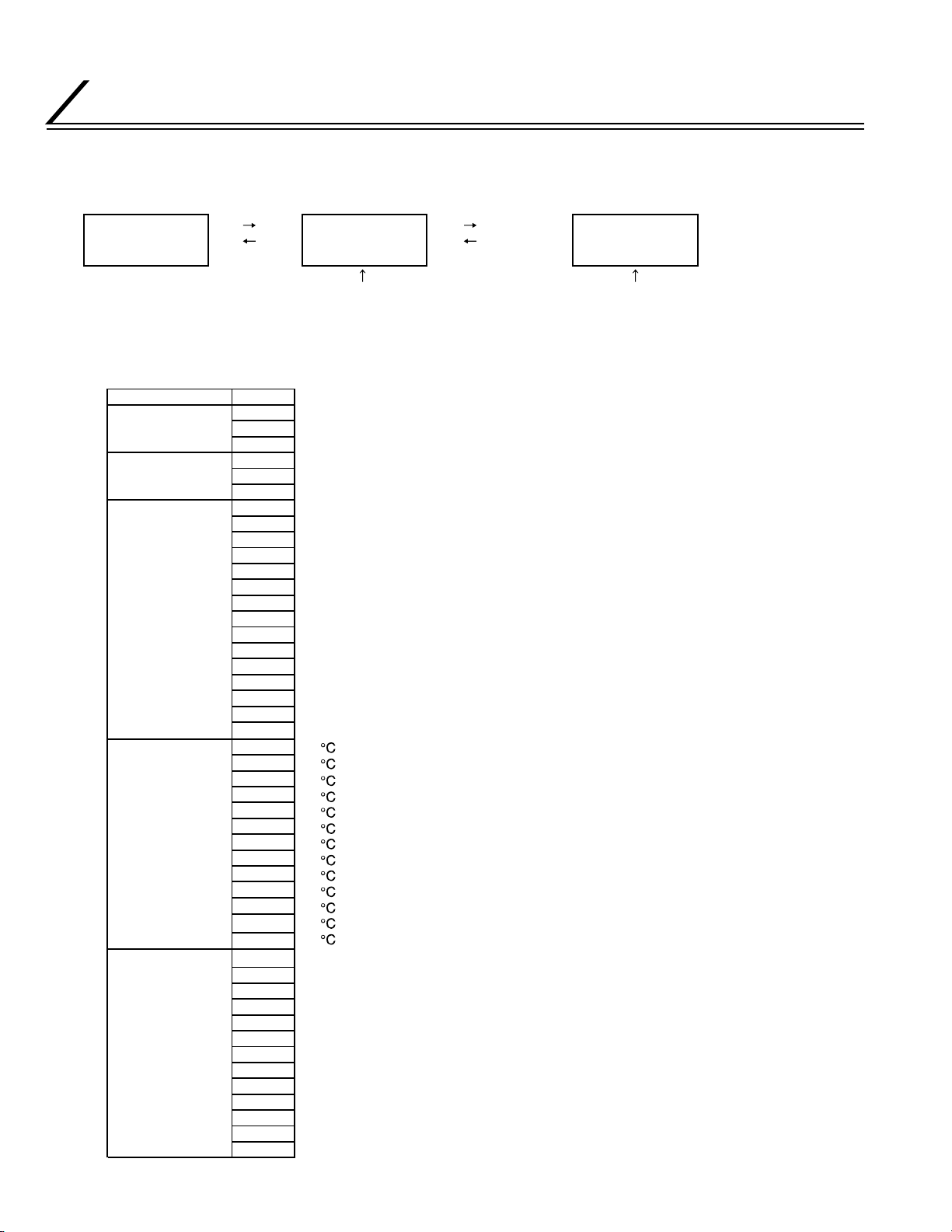
Setting Items
Mode
Film
Film Position
Temp
Speed
Setting value
Single
Both
Pass
1mil
0.6mil
Overlay
-7
-6
-5
-4
-3
-2
-1
0
1
2
3
4
5
6
7
120
125
130
135
140
145
150
155
160
165
170
175
180
4
4.5
5
5.5
6
6.5
7
7.5
8
8.5
9
9.5
10
Single side laminate
Duplex laminate(Indicate when printer setting on CX-120)
No laminate (Card transport)
The patch position of the card is towards the left
Shifting to the next setting moves the patch position by approx. 0.17mm.
Important:
The setting range is determined by the settings in Card offset in Service Mode.
The patch position of the card is towards the right
120
125
130
135
140
145
150
155
160
165
170
175
180
4mm/s
4.5mm/s
5mm/s
5.5mm/s
6mm/s
6.5mm/s
7mm/s
7.5mm/s
8mm/s
8.5mm/s
9mm/s
9.5mm/s
10mm/s
12
USING SERVICE MODE
The card cooling fan does not rotate when laminating
Off
The card cooling fan rotates when laminating(Air flow:Low)
Low
The card cooling fan rotates when laminating(Air flow:Half)
Card Fan
Cool Time
Power Save
LCD Contrast
Cleaning
2. SERVICE MODE
Entry method:
When the machine is in preheat, ready or error state, press the EXIT, MENU, then release the MENU button first to go
into Service Mode.
Half
High
Full
0sec
5sec
7sec
10sec
Off
10
20
30
60
1
2
3
4
5
Without HR
With HR
The card cooling fan rotates when laminating(Air flow:High)
The card cooling fan rotates when laminating(Air flow:Full)
Does not enter Power Save mode
Enters Power Save mode after the machine is in Ready state for 10 minutes
Enters Power Save mode after the machine is in Ready state for 20 minutes
Enters Power Save mode after the machine is in Ready state for 30 minutes
Enters Power Save mode after the machine is in Ready state for 60 minutes
LCD contrast is deepest
LCD contrast is palest
Cleaning of transport roller (heat roller is not pressed)
Cleaning of heat roller (heat roller is pressed)
Setting Items
Card Offset
Sensor
Motor
Temp
Ver
Total
Mk.SensLvl
Temp+Gain
Temp-Gain
Printer
Motor-N
H.Time
H.Time Init
Setting value
-7
-6
-5
-4
-3
-2
-1
0
1
2
3
4
5
6
7
Card Motor
Film Motor
Cam Motor
1
2
3
0
0.5
1
1.5
2
0
0.5
1
1.5
2
CX210
CX-120
Number of
rotations
∗∗∗
The patch position of the card is towards the left
Shifting to the next setting moves the patch position by approx. 0.17mm.
The patch position of the card is towards the right
Not used, HR2, HR1, Black mark, End mark, Card exit, Laminate position, Card entrance
Card transport motor rotates
Film reeling motor rotates
Press the heat roller and return to standby position
Heat roller thermistor output (hex decimal number)
Firm ware Version
Laminated panels
Film (Black) mark sensor sensitivity setting
Standard setting : 1
+ Adjustment gain of the set interior temperature adjustment for heat roller temperature
Standard setting : 2
- Adjustment gain of the set interior temperature adjustment for heat roller temperature
Standard setting : 1.5
Connect CX210, CX-320 and CX-3** series
Connect CX-120 and CX-1** series
Number of rotations of film reeling motor
(rpm)
Heated hours
Initializing heated hours
This setting value will be neglect
and give priority to the setting of
the connecting printer.
13
USING SERVICE MODE
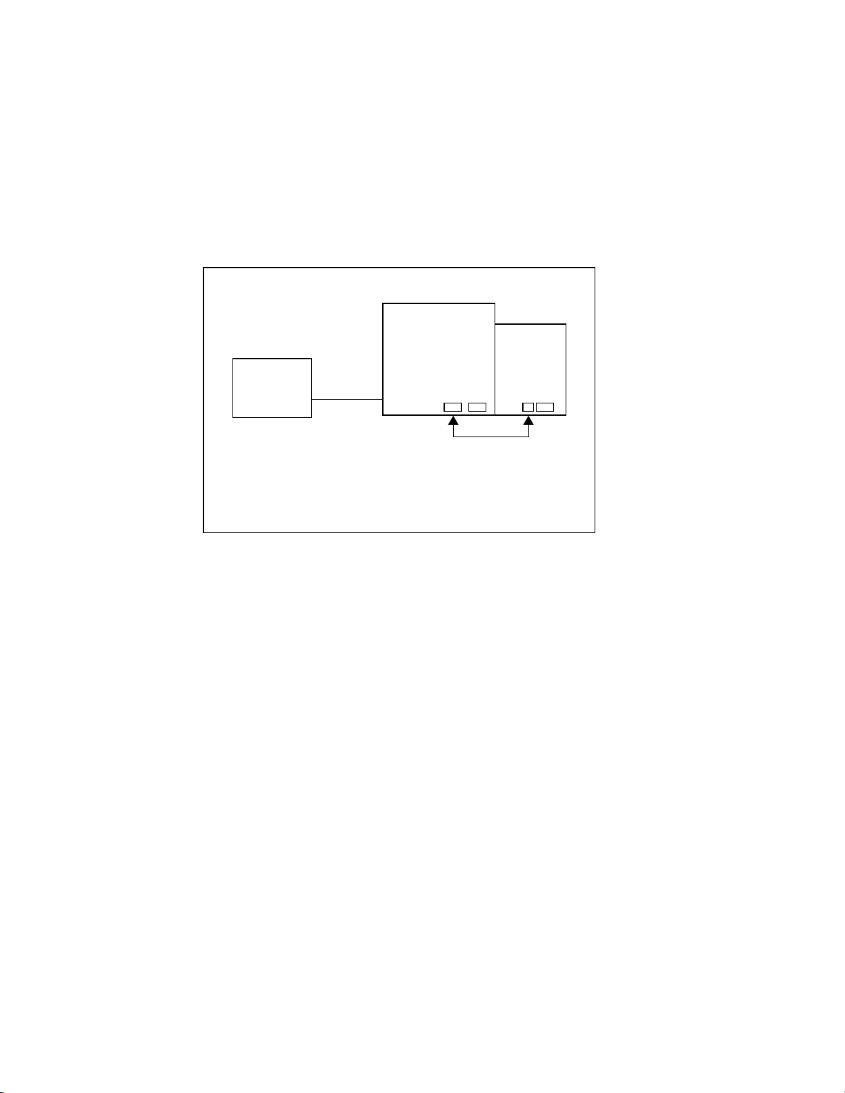
3. FIRMWARE UPDATE
Check the original setting parameter of laminator before downloading, because they may be changed after download.
<CAUTION> Tu rn of the power of printers and laminators, before connecting or disconnecting the cable between the
printers and laminators otherwise some malfunction may be caused.
3.1 Connecting with CX210
(1) Connect the laminator and printer with the Laminator communication cable.
[The connect position of printer is different from usually. Before operating update, connect the cable between
OPTION1(printer) and PRINTER(laminator) as drawing below; ]
CX210
PC
SCSI
CL-500
OPTION1
(DSUB15)
(Back view)
Fig. 1
(2) Turn on the power of laminator.
(3) Turn on the power of printer.
(4) Communication Error will be occurred on printer.
(5) Set printer to ‘download’ mode included in maintenance mode, and update the firmware (Lami***.icf) with printer
downloading tool.
While handling update, laminator can’t display it’s status on the front panel, and printer shows “Downloading Keep
Power On” on the LCD display.
<CAUTION>
It takes about 1 ~ 2 minutes to finish the procedure of download. Don’t turn off the power of laminator and printer.
(6) After complete the download correctly, the laminator start the initialize by itself and LCD display of printer change to
“Download Ready” .
(7) Turn off the power of laminator and printer, and connect the communication cable between laminator and printer.
PRINTER
(DSUB9)
14
 Loading...