

DNP 1100DI Installation Manual
1100DI IN-LINE WIRELESS
RECEIVER
Installation Guide
PROGRAM THE PANEL
Refer to the panel programming guide as needed. After completing
each of the following steps, press CMD to advance to the next
prompt.
1. At a keypad, enter 6653 (PROG) to access the Programmer
menu.
2. At SYSTEM OPTIONS, program a HOUSE CODE between
1 and 50. After turning on the house code, an XT50 will
display RECEIVER NO YES. Select NO. XT30 Series panels
can only work with external receivers. For more information,
refer to “House Code Explained”.
3. Press CMD until STOP displays. Press a top row select key or
area to save programming.
WIRE AND MOUNT THE RECEIVER
Refer to Figure 2 when mounting and wiring the receiver.
1. Remove the cover from the plastic housing.
2. Connect one end of the wire harness to the 1100DI bus
header. Connect the other end to the panel Keypad Bus.
3. Use the included screw to secure the 1100DI to the wall.
4. Snap the cover back on to the base.
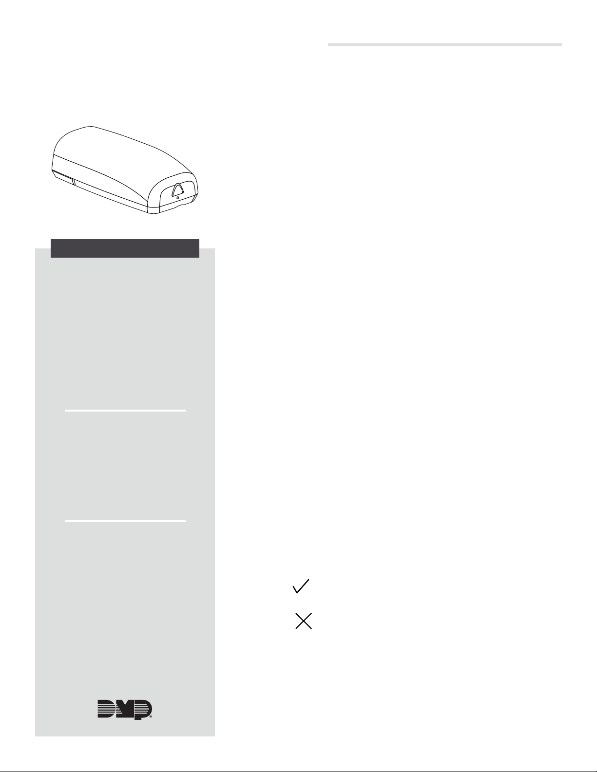
Figure 1: 1100DI In-Line Receiver
DESCRIPTION
The 1100DI provides two‑way,
supervised communication using
900MHz frequency hopping spread
spectrum technology. The 1100DI
In‑Line Wireless Receiver provides
up to 32 wireless zones for XT30/
XT50 Series Version 102 or higher.
The compact design allows the
receiver to be installed anywhere
along the panel keypad bus, such
as next to a keypad. The wireless
system is designed so only one 1100
receiver is used per panel.
1
2
Compatibility
• XT30/XT50 Series panels with
firmware Version 102 or higher
• For wireless compatibility, refer
to the DMP 1100 Series Wireless
Compatibility Guide (LT‑1029)
What is Included?
• One Model 1100DI Wireless
Receiver with housing
• One 4‑wire harness
• Hardware pack
3
SELECT A LOCATION
The receiver should be centrally located between 1100 Series
transmitters used in the installation and no more than 500 feet
(152 meters) away from the panel. Use an 1106 Series Universal
Wireless Transmitter to perform an LED survey.
1. With the cover removed, hold the transmitter in the desired
location.
2. Press the tamper switch to send data to the panel and
determine if communication is confirmed or faulty.
Confirmed: If communication is confirmed, for each
press or release of the tamper switch, the LED blinks
immediately on and immediately o.
Faulty: If communication is faulty, the LED remains on
for about 8 seconds or flashes multiple times in quick
succession. Relocate the receiver until the LED confirms
clear communication.
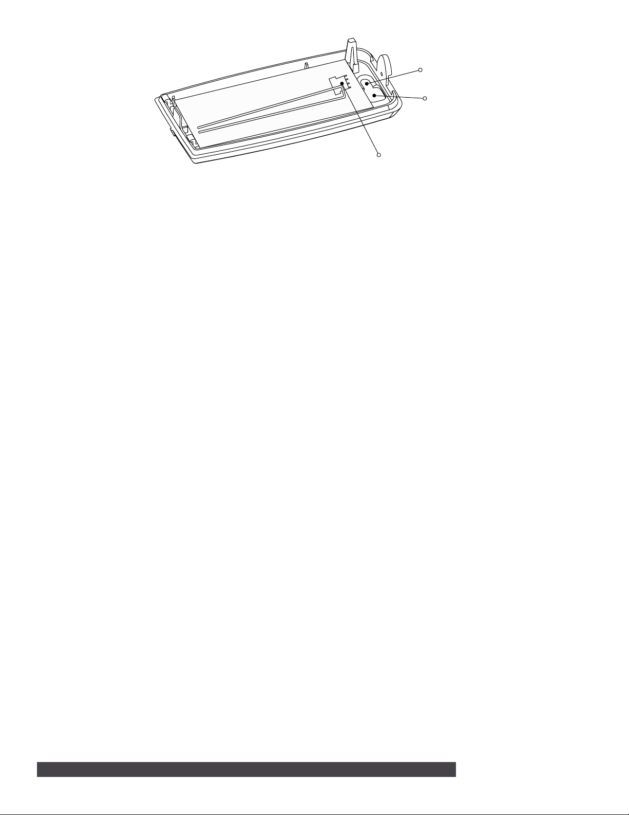
Mounting Hole
Wire Opening
Bus Header
Figure 2: PCB and Mounting Holes
ADDITIONAL INFORMATION
Wiring Specifications
DMP recommends using 18 or 22 AWG for all LX‑Bus and Keypad Bus connections. The maximum wire distance between
any module and the DMP Keypad Bus or LX‑Bus circuit is 10 feet. To increase the wiring distance, install an auxiliary
power supply, such as a DMP Model 505‑12. Maximum voltage drop between a panel or auxiliary power supply and any
device is 2.0 VDC. If the voltage at any device is less than the required level, add an auxiliary power supply at the end of
the circuit.
To maintain auxiliary power integrity when using 22‑gauge wire on Keypad Bus circuits, do not exceed 500 feet. When
using 18‑gauge wire, do not exceed 1,000 feet. Maximum distance for any bus circuit is 2,500 feet regardless of wire
gauge. Each 2,500 foot bus circuit supports a maximum of 40 LX‑Bus devices.
For additional information refer to the LX‑Bus/Keypad Bus Wiring Application Note (LT‑2031) and the 710 Bus Splitter/
Repeater Module Installation Guide (LT‑0310).
LED Operation
Two LEDs display receiver operation and activity.
• Green LED: Flashes to indicate data is being sent to the panel.
• Red LED: Steady to indicate memory upload. O when upload is complete.
House Code Explained
The house code identifies the panel, receiver, and transmitters to each other. The 1100DI automatically sends the
specified house code to wireless transmitters when transmitter serial numbers are programmed into the panel. The
receiver only listens for transmissions using the specified house code or the programmed transmitters’ serial numbers.
Transmitter Supervision Time
For Listed installations, program the transmitter supervision time in panel zone programming as listed in Table 1. Refer to
the panel programming guide for complete wireless programming information.
2 1100DI INSTALLATION GUIDE | DIGITAL MONITORING PRODUCTS
 Loading...