


Getting Started Guide For
D-Link Managed Switches
Documentation also available on
CD and D-Link Website

About This Guide
Desktop or Shelf Installation
This guide gives step-by-step instructions for setting up all
D-Link managed switches and relative Warranty, Safety,
Regulatory, and Environment Notice. Please note that the
ENGLISH
model you have purchased may appear slightly different
from those shown in the illustrations.
For more detailed information about your switch, its
components, making network connections, and technical
specications, please refer to the User’s Guide included
with your switch.
Step 1 – Unpacking
Open the shipping carton and carefully unpack its
contents. Please consult the packing list located in the
User Guide to make sure all items are present and
undamaged. If any item is missing or damaged, please
contact your local D-Link reseller for replacement.
Items Included in Switch Packages
Type of Switch *
Item
Device Yes Yes Yes Yes
RS-232 Cable
(Printer cable)
Rack
Mounting
Brackets
Rubber Feet Yes Yes Yes Yes
Power Cord
(Adapter)
User’s Guide Yes Yes Yes Yes
Multi-lingual
QIG **
Unmanaged
Palm
No No Yes Yes
No Yes Yes Yes
Yes Yes Yes Yes
Yes Yes Yes Yes
Desktop/Rack
Mount
Smart or
Managed
Chassis
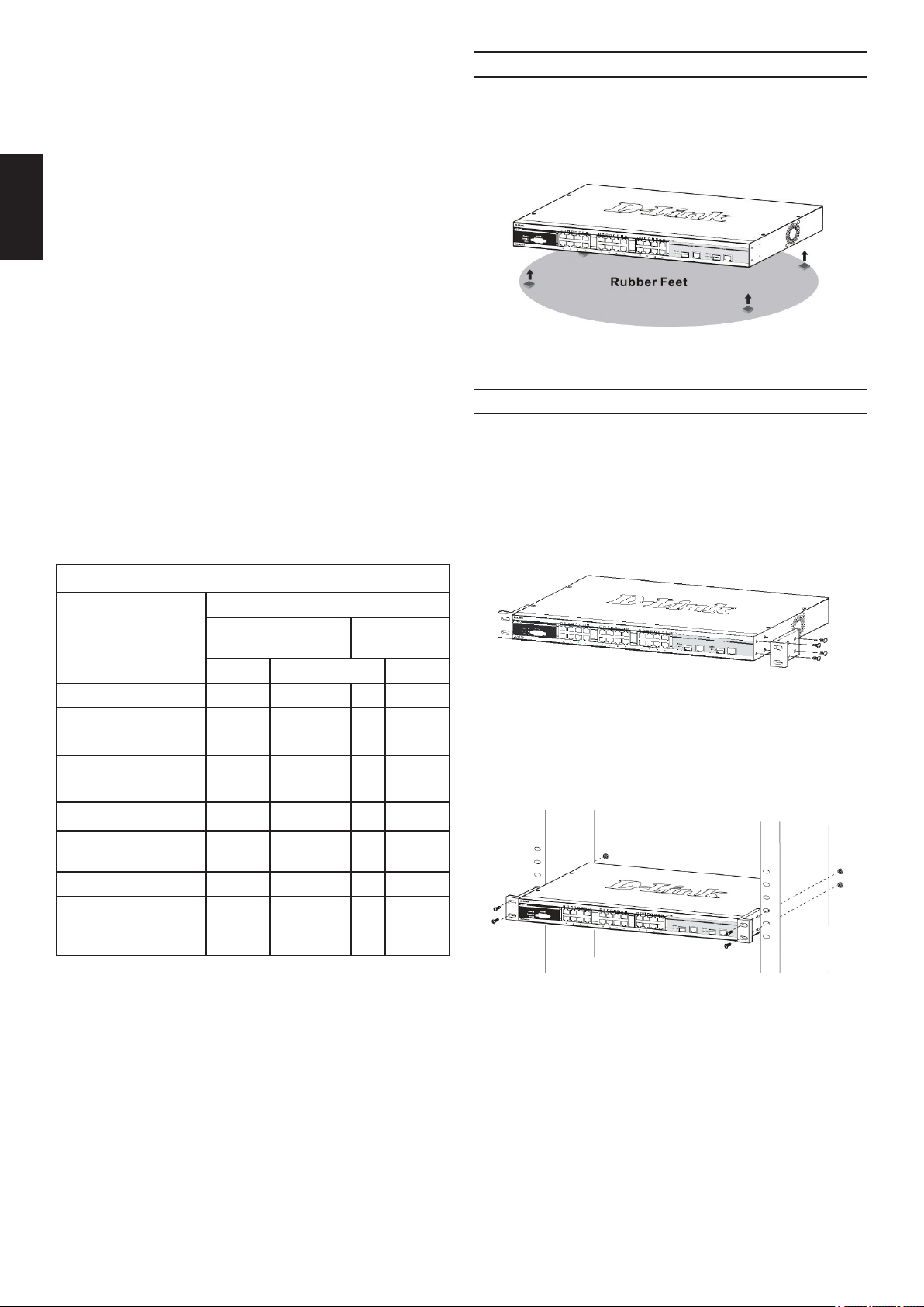
When installing the switch on a desktop or shelf, the
rubber feet included with the device must be attached
on the bottom at each corner of the device’s base. Allow
enough ventilation space between the device and the
objects around it.
Figure 1. Attaching the rubber feet
Rack Installation
The switch can be mounted in an EIA standard size
19-inch rack, which can be placed in a wiring closet with
other equipment. To install, attach the mounting brackets
to the switch’s side panels (one on each side) and
secure them with the screws provided (please note that
these brackets are not designed for palm size switches).
Figure 2. Attaching the mounting brackets
Then, use the screws provided with the equipment rack
to mount the switch in the rack.
*Stackable switches, unlike standalone switches, should also
include a cascade cable.
Step 2 – Switch Installation
For safe switch installation and operation, it is
recommended that you:
• Visually inspect the power cord to see that it is secured
fully to the AC power connector.
• Make sure that there is proper heat dissipation and
adequate ventilation around the switch.
• Do not place heavy objects on the switch
2
Figure 3. Installing the switch in a standard-sized
equipment rack

Step 3 – Plugging in the AC
Management Options
ENGLISH
Power Cord
Users may now connect the AC power cord to an
electrical outlet (preferably one that is grounded and
surge protected) and into the rear of the switch.
Figure 4. Plugging the switch into an outlet
Power Failure
As a precaution, the switch should be unplugged in
case of power failure. When power is resumed, plug the
switch back in.
Connecting DC power to the DC
This system may be managed out-of-band through
the console port on the front/back panel or in-band
using Telnet. The user may also choose the web-based
management, accessible through a web browser. Each
Switch must be assigned its own IP Address, which is
used for communication with an SNMP network manager
or other TCP/IP application (for example BOOTP, TFTP).
The Switch’s default IP address is 10.90.90.90. The user
can change the default Switch IP address to meet the
specication of your networking address scheme.
Web-based Management Interface
After a successful physical installation, you can congure
the Switch, monitor the LED panel, and display statistics
graphically using a web browser, such as Netscape
Navigator (version 6.2 and higher) or Microsoft® Internet
Explorer (version 5.0 and higher).
The equipment you need to begin the web conguration
of your device:
• A PC with a RJ-45 Ethernet connection
• A standard Ethernet cable
Step 1
Connect the Ethernet cable to any of the ports in front
panel of the switch and to the Ethernet port on the PC.
power supported Switch
Follow the instructions below to connect the DC power
supply of a DC powered switch to a DC power source.
Figure 5. Power connections attached to contacts on
assembly
Firmly attach the DC power to the negative and positive
contacts on the wiring assembly.
• The negative pole (-) connects to the -48V contact.
• The positive pole (+) connects to the -48V Return
contact.
• If available, the earth ground may be connected to
center contact post.
• Tighten the contact screws so the connection is
secure.
Figure 6. Connected to an end node via Ethernet
cable
Step 2
To begin managing your Switch, open the browser you
have installed on your computer and enter the IP address
of your device in the format http://xxx.xxx.xxx.xxx where
the xxx is a number between 1-255. For the user who
wants to access the device for the very rst time, enter the
factory default IP address 10.90.90.90, and press Enter.
Figure 7. Enter the IP address 10.90.90.90 in the web
browser
3

Step 3
This opens the management module’s user
authentication window, as seen below.
ENGLISH
1. Connect the female connector of the RS-232 cable
directly to the console port on the Switch, and tighten
the captive retaining screws.
2. Connect the other end of the cable to a terminal or to
the serial connector of a computer running terminal
emulation software. Set the terminal emulation
software as follows:
3. Select the appropriate serial port (COM port 1 or COM
port 2).
4. Set the data rate. (9600 or 115200)
5. Set the data format to 8 data bits, 1 stop bit, and no
parity.
6. Set ow control to none.
Figure 8. Enter Network Password window
Leave both the User Name eld and the Password eld
blank and click OK. This will open the Web-based user
interface.
NOTE: The Switch’s factory
default IP address is 10.90.90.90
with a subnet mask of 255.0.0.0
and a default gateway of 0.0.0.0.
Connecting the Console Port
(RS-232 DCE)
The Switch provides an RS-232 serial port that enables
a connection to a computer or terminal for monitoring
and conguring the Switch. This port is a female DB-9
connector, implemented as a data communication terminal
equipment (DCE) connection.
To use the console port, you need the following equipment:
• A terminal or a computer with both a serial port and the
ability to emulate a terminal.
• A null modem or crossover RS-232 cable with a female
DB-9 connector for the console port on the Switch.
7. Under Properties, select VT100 for Emulation mode.
8. Select Terminal keys for Function, Arrow, and Ctrl
keys. Ensure that you select Terminal keys (not
Windows keys).
9. After you have correctly set up the terminal, plug the
power cable into the power receptacle on the back
of the Switch. The boot sequence appears in the
terminal.
10. After the boot sequence completes, the console login
screen displays.
11. If you have not logged into the command line
interface (CLI) program, press the Enter key at the
User name and password prompts. There is no
default user name and password for the Switch.
The administrator must rstly create user names
and passwords. If you have previously set up user
accounts, log in and continue to congure the Switch.
12. Enter the commands to complete your desired
tasks. Many commands require administrator-level
access privileges. See the Command Line Interface
Reference Manual on the documentation CD for a list
of all commands and additional information using the
CLI.
13. When you have completed your tasks, exit the
session with the logout command or close the
emulator program.
Figure 9. Connected to an end node via console
cable
To connect a terminal to the console port:
4
Telnet Management
Users may also access the switch console through Telnet
using your PC’s Command Prompt. To access it from your
computer, users must rst ensure that a valid connection
is made through the Ethernet port of the Switch and your
PC, and then click Start > Programs > Accessories >
Command Prompt on your computer. Once the console
window opens, enter the command telnet 10.90.90.90
(depending on congured IP address) and press Enter
on your keyboard. You should be directed to the opening
console screen for the Command Line Interface of
the switch, press the Enter key at the User name and
password prompts. There is no default user name and
password for the Switch.

SNMP-Based Management
You can manage the Switch with D-Link D-View or any
SNMP-compatible console program. The SNMP function
is default Disabled for D-Link managed switches.
D-View SNMP Network Management System is a
comprehensive standard-based management tool
designed to centrally manage critical network. D-View
provides useful tools to allow network administrators to
effectively manage device congurations, fault tolerance,
performance and security. D-Link offers free D-View trial
version download that allows you to free evaluate the
products for 30 days. You can download the trial version
from http://dview.dlink.com.tw/support_Download_Trial_
Version.asp
ENGLISH
Additional Information
If you are encountering problems setting up your network,
please refer to the User’s Guide that came with the switch.
It contains many more rules, charts, explanations and
examples to help you get your network up and running.
Additional help is available through our ofces listed at the
back of the User’s Guide or online. To know more about
D-Link products or marketing information, please visit the
website http://www.dlink.com.
Warranty Information
The D-Link Limited Lifetime Warranty information is
available at http://warranty.dlink.com/
5
Einleitung
Tisch- oder Regal-Installation
Diese Anleitung weist Sie Schritt für Schritt an, wie
Sie alle D-Link Managed Switches einrichten können
und bietet dem Produkt entsprechende Garantien,
Sicherheitshinweise, Hinweise zur Einhaltung rechtlicher
Vorschriften sowie zur Umweltverträglichkeit.
Beachten Sie, dass Ihr Modell sich möglicherweise
geringfügig von den Abbildungen unterscheidet.
DEUTSCH
Nähere Informationen über Ihren Switch und
seine Komponenten sowie zur Herstellung von
Netzwerkverbindungen und zu den entsprechenden
technischen Daten nden Sie im Benutzerhandbuch, das
Ihrem Switch beiliegt.
Schritt 1 – Auspacken
Öffnen Sie den Versandkarton und entnehmen Sie
vorsichtig den Inhalt. Überprüfen Sie die Unversehrtheit
und Vollständigkeit anhand der Liste des Lieferumfanges
im Handbuch. Falls etwas fehlen sollte oder beschädigt
ist wenden Sie sich bitte an Ihren D-Link Händler, um
Ersatz zu bekommen.
Für die Tisch- oder Regal-Installation befestigen Sie
die mitgelieferten Gummifüße auf der Unterseite des
Switches an den vier Ecken. Sorgen Sie um den Switch
herum für ausreichende Belüftung.
Abbildung 1. Befestigung der Gummifüße
Rack Installation
Der Rackmount-Switch kann in ein Standard 19-Zoll Rack
als Bestandteil der Netzwerkverkabelung zusammen mit
anderen Geräten eingebaut warden.Schrauben Sie die
Rackmontage-Winkel mit den mitglieferten Schrauben
vorne seitlich an den Switch (bitte beachten Sie, dass
Switches in Desktop-Größe diese Option nicht besitzen).
Inhalt der Switch Verpackung
Switch Typ *
Teil
Gerät Ja Ja Ja Ja
RS-232 Kabel
(Seriell)
Rack
Einbaumaterial
Gummifüße Ja Ja Ja Ja
Stromkabel
(Netzteil)
Handbuch Ja Ja Ja Ja
Mehrsprachige
Installationsanleitung*
*Bei Stackable Switches ist auch ein Stackkabel enthalten.
Unmanaged
Desktop Rack Mount Chassis
Nein
Nein Ja Ja Ja
Ja Ja Ja Ja
Ja Ja Ja Ja
Ja
(Managed)
Smart or
Managed
Ja Ja
Abbildung 2. Befestigung der Rack-Einbauwinkel
Danach wird der Switch mit den zusammen mit dem
Rack gelieferten Schrauben eingebaut.
Abbildung 3. Einbau im Standard 19-Zoll Rack
Schritt 2 – Installation
Um den Switch sicher zu installieren und in Betrieb
zunehmen, beachten Sie bitte die folgenden Hinweise:
• Vergewissern Sie sich, dass das Stromkabel fest in der
Stromeingangsbuchse steckt.
• Sorgen Sie für einen gute Wärmeableitung und
ausreichende Luftzirkulation am Aufstellungsort.
• Stellen Sie keine schweren Gegenstände auf den
Switch.
6

Schritt 3 – Stromanschluss
Stecken Sie nun das Stromkabel in die Steckdose der
Stromversorgung. Eine abgesicherte Stromquelle mit
Schutzkontakt ist empfehlenswert.
Abbildung 4. Stromanschluss
Stromausfall
Bei Stromausfall sollte der Switch vorsorglich von der
Stromversorgung getrennt werden. Erst wenn der Strom
wieder da ist, sollte er wieder angeschlossen werden.
Schritt 4 –
Netzwerkverbindungen
Computer, Server und Router können mit geeigneten
Netzwerkkabeln am Switch angeschlossen warden.
Nähere Information zu den verschiedenen Kabeltypen
entnehmen sie bitte dem Handbuch. Kurze Zeit nach dem
Einschalten sehen Sie, welche Netzwerkverbindungen
bestehen. Eine bestehende Netzwerkverbindung
erkennen Sie an der leuchtenden Link/Act LED des
jeweiligen Anschlusses (Port).
DEUTSCH
Abbildung 5. Montage der Stromanschlüsse an den
Kontakten
Verbinden Sie die Minus- und Pluskabel der
Stromversorgung fest mit den Kontakten des Netzteiles.
• Der Minuspol (-) wird mit dem -48V Kontakt
verbunden.
• Der Pluspol (+) wird mit dem -48V Return Kontakt
verbunden.
• Falls ein Schutzkontakt (Erde) vorhanden ist, wird
dieser mit dem mittleren Kontakt verbunden.
• Ziehen Sie die Schrauben an den Kontakten fest an.
Management Optionen
Das Switch System kann von außen (out-of-band)
über den Konsolenanschluss auf der Vorder- oder
Rückseite oder intern (in-band) über TELNET verwaltet
werden. Außerdem steht intern noch das Web-basierte
Management, das mit einem Web-Browser geöffnet
wird, zur Verfügung. Jedem Switch muss eine eindeutige
IPAdresse zugewiesen werden, die zur Kommunikation
mit einem SNMP Netzwerkmanagement System oder
für andere TCP/IP Anwendungen (z.B. BOOTP, TFTP)
benötigt wird. Die Werkseinstellung der IP-Adresse des
Switches ist 10.90.90.90. Diese IP-Adresse kann zur
Anpassung an die eigene Netzwerkadressierung geändert
werden.
Weitere Informationen
Bei Problemen mit der Einrichtung des Netzwerkes
schauen Sie zuerst im Switch-Handbuch nach. Es enthält
viele weiteres Regeln, Übersichten, Erklärungen und
Beispiele zur erfolgreichen Einrichtung eines lokalen
Netzwerkes. Zusätzliche Hilfe erhalten Sie auch Online
auf http://www.dlink.de,http://www.dlink.at, http://www.
dlink.ch oder von den D-Link Niederlassungen, deren
Adressen auf der letzten Seite des Handbuches stehen.
Stromanschluss am Switch mit
Gleichspannungsnetzteil (DC)
Befolgen Sie die Anweisungen unten, um das
Gleichspannungsnetzteil eines DC-Switchmodelles an
eine Gleichspannungsquelle anzuschließen.
Web-Management
Nach der physischen Geräteinstallation, können Sie
mit der Konfguration beginnen, die LED-Anzeigen
überwachen und Statistiken über einen Web-Browser
graphisch anzeigen lassen. Der Browser sollte die
Mindestanforderungen erfüllen wie das beim Netscape
Navigator (Version 6.2 and höher) oder Microsoft® Internet
Explorer (Version 5.0 und höher) der Fall ist.
Folgende Ausrüstung benötigen sie für das WebManagement:
• Einen PC mit RJ-45 Ethernet Anschluss
• Ein Standard Ethernetkabel
7

Schritt 1
Verbinden Sie das Ethernetkabel mit einem beliebigen
Anschluss des Switches und mit dem Ethernetanschluss
des PCs.
DEUTSCH
Hinweis: Die Werkseinstellung
der IP-Adresse des Switches ist
10.90.90.90 mit der
Subnetzmaske 255.0.0.0 und
dem Default Gateway 0.0.0.0.
Verbindung über den Konsolenanschluss
(RS-232, DCE)
Der Switch besitzt einen seriellen RS-232 Anschluss,
der die Überwachung und die Konguration über einen
Computer oder ein Terminal von außen ermöglicht.
Dieser Anschluss hat eine DB-9 Buchse, die als
Datenübertragungseinrichtung (DCE) ausgelegt ist.
Abbildung 6. Verbindung eines Endgerätes über
Ethernetkabel
Schritt 2
Öffnen Sie den Browser, der auf Ihrem Computer
installiert ist, und geben Sie die Web-Adresse Ihres
Gerätes im Format http://xxx.xxx.xxx.xxx ein, wobei xxx
eine Zahl zwischen 1 und 255 ist. Beim erstmaligen
Kontakt zu dem Switch mit Werkseinstellung verwenden
Sie die Adresse http://10.90.90.90 und klicken Sie auf
Enter.
Abbildung 7. Eingabe der IP-Adresse 10.90.90.90 im
Web-Browser
Schritt 3
Es öffnet sich ein neues Fenster zur Benutzeranmeldung
wie abgebildet.
Folgende Ausrüstung wird zur Verwendung des
Konsolenanschlusses benötigt:
• Ein Terminal mit seriellem Anschluss oder ein PC mit
seriellem Anschluss und einer Terminalemulation.
• Ein Nullmodemkabel bzw. gekreuztes RS-232 Kabel
mit einem DB-9 Stecker zur Verbindung mit dem
Konsolenanschluss des Switches.
Abbildung 9. Endgerät verbunden über ein
Konsolenkabel
So verbinden Sie ein Terminal über den
Konsolenanschluss:
1.Verbinden Sie den Stecker des RS-232-Kabels mit dem
Konsolenanschluss des Switches und ziehen sie die
Halteschrauben an.
Abbildung 8. Eingabe des Kennwortes im
Anmeldefenster
Lassen die Felder User Name (Benutzername) und
Password (Kennwort) leer und klicken Sie auf OK.
Danach öffnet sich das Web-Management Menü.
8
2.Verbinden Sie das andere Ende des Kabels mit dem
seriellen Anschluss eines Terminals oder eines PCs
mit Terminalemulation. Stellen Sie die Parameter der
Terminalemulation wie folgt ein:
3.Wählen Sie den richtigen seriellen Anschluss (z.B.
COM1 oder COM2).
4.Stellen Sie die Datenrate ein. (9600 or 115200)
5.Stellen Sie das Datenformat auf 8 Bit, 1 Stop-Bit, keine
Parität.
6.Schalten Sie die Flußkontrolle aus.
7.Stellen Sie in den Eigenschaften VT100 Emulation ein.
8.Wählen Sie die Terminal-Tastenbelegung für Funktions-,
Pfeil- und Steuerungstasten aus. Die WindowsTastenbelegung darf nicht aktiviert sein.
9.Nach der korrekten Einrichtung und dem Start des
Terminals stecken Sie das Stromkabel in die Buchse des
Switchnetzteiles. Die Meldungen des Bootvorganges
erscheinen im Terminal.

10.Nach dem Abschluss des Bootvorganges wird die
Konsolenanmeldung angezeigt.
11.Wenn Sie sich zum ersten Mal am
Kommandozeilenprogramm (CLI) anmelden, drücken
Sie bei den Eingabeaufforderungen User Name
(Benutzername) und Password (Kennwort) einfach nur
Enter. Erst wenn der Administrator Benutzernamen und
Kennwörter eingerichtet hat, müssen Sie an dieser Stelle
Ihren Benutzernamen und Ihr Kennwort eingeben, um
den Switch kongurieren und überwachen zu können.
12.Geben Sie nun am Prompt die entsprechenden Befehle
ein. Viele Kommandos erfordern Administratorrechte.
Im elektronischen CLIReferenzhandbuch auf der CD
nden Sie die Beschreibung aller Kommandos und
weitere wichtige Informationen.
DEUTSCH
13.Wenn sie fertig sind, beenden Sie die Sitzung mit
dem Befehl Logout (Abmeldung) und schließen Sie das
Terminalprogramm.
TELNET Management
Die Switch-Kommandozeile kann intern auch über
TELNET und die Eingabeaufforderung des PCs erreicht
werden. Dafür muss zunächst eine Ethernetverbindung
vom PC zum Switch aufgebaut sein. Öffnen Sie die
Eingabeaufforderung Ihres Computers (z.B. in Windows
über Start > Programme > Zubehör > Eingabeaufforderung).
Am Prompt geben Sie den Befehl telnet 10.90.90.90
(Werkseinstellung der Switch IPAdresse) ein und drücken
dann auf Enter. Sie sollten nun die Eingabeaufforderung
zur Anmeldung am Kommandozeilenprogramm des
Switches erreicht haben. drücken Sie bei User Name
(Benutzername) und Password (Kennwort) einfach
nur Enter In der Werkseinstellung gibt es noch keine
Benutzernamen und Kennwörter.
SNMP Netzwerkmanagement
Weitere Informationen
Wenn beim Einrichten Ihres Netzwerks Probleme
auftreten sollten, schlagen Sie bitte im Benutzerhandbuch
nach, das mit dem Switch geliefert wurde. Hier nden Sie
weitere Regeln, Diagramme, Erläuterungen und Beispiele,
die Ihnen bei der Inbetriebnahme Ihres Netzwerks helfen.
Weitere Hilfe und Unterstützung steht Ihnen von unseren
auf der Rückseite des Benutzerhandbuchs aufgeführten
Niederlassungen oder online zur Verfügung. Wenn Sie
an weiteren Einzelheiten zu den Produkten oder an
Marketinginformationen von D-Link interessiert sind,
besuchen Sie bitte die Website http://www.dlink.com
Garantiebestimmungen
Informationen zur eingeschränkten Garantie auf
Lebenszeit für Produkte von D-Link nden Sie unter http://
warranty.dlink.com/
Der Switch kann mit dem D-Link D-View SNMP
Netzwerkmanagement oder einer anderen
SNMPkompatiblen Management Software. Das SNMP
Protokoll ist in der Werkseinstellung der D-Link Managed
Switches ausgeschaltet.
Bei dem D-View SNMP Network Management System
handelt es sich um ein umfassendes, auf entsprechenden
Standards basierendes Management Tool, das einer
unternehmens- und geschäftskritischen zentralen
Netzwerkverwaltung dient. D-View bietet nützliche
Funktionen, die Netzwerkadministratoren die effektive
Durchführung und Verwaltung von Gerätekongurationen,
Fehlertoleranzen, Performance- und Sicherheitsoptionen
ermöglichen. D-Link stellt Ihnen D-View als kostenlose
Testversion zur freien Beurteilung des Produkts für den
Zeitraum von 30 Tagen zur Verfügung. Sie können die
Testversion hier herunterladen: http://dview.dlink.com.tw/
support_Download_Trial_Version.asp
9

Introduction
Étape 2 : installation du switch
Ce guide contient des instructions détaillées concernant
la conguration de tous les commutateurs gérés par
D-Link, ainsi que les déclarations de garantie, sécurité,
règlementaires et environnementales correspondantes.
Notez que le modèle que vous avez acheté peut
légèrement différer de celui illustré sur les gures.
Pour de plus amples informations sur votre commutateur,
ses composants, sa connexion au réseau et ses
caractéristiques techniques, veuillez consulter le Guide
d’utilisation associé.
Étape 1 : déballage
FRANÇAIS
Ouvrez le carton d’expédition et sortez-en le contenu
avec précaution. Le Guide de l’utilisateur contient une
liste des éléments devant se trouver dans l’emballage
; en vous y reportant, vériez que tous les composants
sont présents et en parfait état. Si un élément est absent
ou détérioré, contactez votre revendeur D-Link pour en
obtenir un nouveau.
Pour installer et utiliser le switch en toute sécurité, nous
vous recommandons de procéder comme suit :
• Inspectez visuellement le cordon d’alimentation et
assurez-vous du parfait assujettissement du connecteur
d’alimentation secteur.
• Vériez que le switch présente une dissipation de chaleur
adaptée et qu’il est entouré d’un espace sufsant pour
garantir une bonne ventilation.
• Ne posez pas d’objets lourds sur le switch.
Installation sur un bureau ou une étagère
Pour installer le switch sur un bureau ou une étagère,
vous devez lui ajouter les pieds en caoutchouc fournis,
aux quatre coins de sa base. À des ns de ventilation,
prévoyez un espace sufsant entre l’appareil et les
objets environnants.
Éléments contenus dans l’emballage d’un
switch
Type de switch*
Non
Élément
Appareil Oui Oui Oui Oui
Câble RS-232
(pour
l’imprimante)
Supports pour
montage en
armoire
Pieds en
caoutchouc
Cordon
d’alimentation
(adaptateur)
Guide de
l’utilisateur
Guide
d’installation
rapide
(multilingue)**
administrable
De bureau/à
Palm
Non Non Oui Oui
Non Oui Oui Oui
Oui Oui Oui Oui
Oui Oui Oui Oui
Oui Oui Oui Oui
Oui Oui Oui Oui
monter
en armoire
Smart ou
administrable
Châssis
Figure 1. Fixation des pieds en caoutchouc
Installation dans une armoire
Vous pouvez monter votre switch dans une armoire 19
pouces EIA standard, à insérer dans une armoire de
câblage avec d’autres équipements. Pour cela, xez les
supports de montage de part et d’autre du panneau avant
du switch, à l’aide des vis fournies dans l’emballage. Notez
que ces supports ne sont pas conçus pour les switches au
format Palm.
Figure 2. Attaching the mounting brackets
Utilisez ensuite les vis fournies pour monter le switch
dans l’armoire.
*Un câble de cascade doit également être fourni avec les
switches empilables (mais pas avec les switches autonomes).
10
Figure 3. Installation du switch dans une armoire de
taille standard

Étape 3 : raccordement au
Raccordement d’un switch
secteur
Maintenant, reliez le switch à une prise de courant
(de préférence une prise mise à la terre et dotée d’un
parasurtenseur) à l’aide du cordon d’alimentation secteur
branché à l’arrière du switch.
Figure 4. Raccordement du switch à une
prise de courant
Panne de courant
En cas de panne de courant, par précaution, débranchez
le switch. Rebranchez-le une fois le courant rétabli.
Étape 4 : présentation des
connexions réseau des appareils
alimenté en courant continu
à une source d’alimentation
continu
Suivez les instructions ci-dessous pour raccorder un switch
alimenté en courant continu à une source d’alimentation
continue.
FRANÇAIS
Figure 5. Raccordement de l’alimentation aux bornes
du switch
Connectez fermement la source d’alimentation continue
aux bornes positive et négative du switch.
• Reliez le pôle négatif (-) à la borne -48V.
• Reliez le pôle positif (+) à la borne -48V Return.
• Le cas échéant, la prise de terre peut être reliée à la
borne centrale.
• Serrez les vis de contact pour garantir une bonne
connexion.
Vous pouvez relier au switch des ordinateurs, des serveurs
et des routeurs à l’aide d’un câblage bre optique adapté
au support concerné. Pour plus d’informations sur les
types de câblage, reportez-vous au Guide de l’utilisateur.
Lorsque vous mettez le switch sous tension, vous pouvez
instantanément visualiser la validité des connexions
réseau. Si une connexion est valide, le voyant Link/Act
(liaison/activité) associé au port correspondant s’allume
sur le panneau avant du switch.
Informations supplémentaires
Si vous rencontrez des problèmes lors de la conguration
du réseau, reportez-vous au Guide de l’utilisateur fourni
avec le switch. Il contient un grand nombre d’instructions,
de croquis, d’explications et d’exemples pour vous aider à
installer votre réseau.
Vous trouverez également une aide supplémentaire en
ligne sur les sites Web http://www.dlink.eu et http://www.
dlink.fr, ou auprès de nos bureaux indiqués au dos du
Guide de l’utilisateur.
Options d’administration
Le système peut être administré en dehors de la bande
passante via le port console du panneau avant/arrière
ou dans la bande passante via Telnet. L’utilisateur peut
également opter pour l’administration sur le Web, via un
navigateur Web. Une adresse IP doit être affectée à chaque
switch. Elle permet de communiquer avec un gestionnaire
de réseau SNMP ou avec d’autres applications TCP/IP
(par exemple, BOOTP, TFTP). L’adresse IP par défaut
du switch est 10.90.90.90. L’utilisateur peut changer
l’adresse IP par défaut du switch pour respecter le plan
d’adressage utilisé par son réseau.
Interface d’administration sur le Web
Lorsque l’installation physique est terminée, vous pouvez
congurer le switch, surveiller les voyants et afcher
des graphiques de statistiques à l’aide d’un navigateur
Web (Netscape Navigator version 6.2 ou supérieure, ou
Microsoft® Internet Explorer version 5.0 ou supérieure,
par exemple).
Pour commencer la conguration Web de votre
équipement, vous avez besoin des éléments suivants :
• PC équipé d’une connexion Ethernet RJ-45
• Câble Ethernet standard
11

Étape 1
Connectez une extrémité du câble Ethernet à l’un des
ports disponibles sur le panneau avant du switch et l’autre
extrémité au port Ethernet de l’ordinateur.
FRANÇAIS
Figure 6. Connexion à un nœud d’extrémité par câble
Ethernet
Étape 2
Pour commencer à gérer votre switch, ouvrez votre
navigateur et saisissez l’adresse IP de votre équipement
au format http://xxx.xxx.xxx.xxx (où xxx représente un
nombre compris entre 1 et 255). Si c’est la première fois
que vous accédez à votre équipement, saisissez l’adresse
IP par défaut 10.90.90.90 et appuyez sur Entrée.
Remarque : L’adresse IP par défaut du switch
est 10.90.90.90 ; son masque de sous-réseau
est 255.0.0.0 et sa passerelle par défaut,
0.0.0.0.
Connexion au port console
(RS-232 DCE)
Le switch est doté d’un port série RS-232, qui permet de
le surveiller et de le congurer via un ordinateur ou un
terminal. Il s’agit d’un connecteur DB-9 femelle jouant le
rôle de connexion à un équipement de transmission de
données.
Pour utiliser le port console, vous avez besoin des
éléments suivants :
• Terminal ou ordinateur équipé d’un port série et capable
d’émuler un terminal.
• Câble RS-232 simulateur de modem avec connecteur
DB-9 femelle pour le port console du switch.
Figure 7. Adresse IP 10.90.90.90 saisie dans le
navigateur Web
Étape 3
La fenêtre d’authentication du module d’administration
apparaît (voir ci-dessous).
Figurez 8. Fenêtre d’authentication Enter
Network Password
Figure 9. Connexion à un nœud d’extrémité par câble
de console
Procédure de connexion d’un terminal
au port console :
1. Connectez directement le connecteur femelle du câble
RS-232 au port console du switch et serrez les vis de
xation captives.
2. Connectez l’autre extrémité du câble à un terminal
ou au port série d’un ordinateur exécutant un logiciel
d’émulation de terminal. Suivez la procédure suivante
pour congurer le logiciel d’émulation de terminal :
3. Sélectionnez le port série approprié (port COM 1 ou port
COM 2).
4. Dénissez le débit de données.
5. Choisissez le format 8 bits de données, 1 bit d’arrêt,
aucune parité.
6. Dénissez le contrôle de ux sur none (aucun).
7. Dans Properties (Propriétés), sélectionnez le mode
VT100 for Emulation (émulation VT100).
Ne saisissez pas de nom d’utilisateur, ni de mot de
passe et cliquez sur OK. L’interface Web s’ouvre.
12
8. Sélectionnez les touches de terminal (Terminal keys)
comme touches de fonctions, èches et Contrôle
(Function, Arrow, and Ctrl keys). Vériez que vous avez
sélectionné les touches de terminal (et non les touches
Windows).
9. Une fois que vous avez conguré correctement le

terminal, raccordez le câble d’alimentation à la prise
située à l’arrière du switch. La séquence de démarrage
apparaît sur le terminal.
10.À la n de la séquence de démarrage, l’écran de
connexion à la console s’afche.
11.Si vous n’êtes pas connecté au programme d’interface
de ligne de commande (CLI), appuyez sur la touche
Entrée lorsque le système vous demande votre
nom d’utilisateur et votre mot de passe. Aucun nom
d’utilisateur ou mot de passe par défaut n’est affecté au
switch. L’administrateur doit commencer par créer des
noms d’utilisateur et des mots de passe. Si vous avez
déjà conguré des comptes utilisateur, ouvrez votre
session et poursuivez la conguration du switch.
12.Saisissez les commandes permettant d’exécuter les
tâches que vous désirez. De nombreuses commandes
nécessitent des droits administrateur. Pour consulter
la liste de toutes les commandes et en savoir plus sur
l’interface de ligne de commande, consultez le manuel
Command Line Interface Reference Manual, disponible
sur le CD de documentation.
13.Une fois votre travail terminé, fermez votre session à
l’aide de la commande de déconnexion ou fermez le
programme d’émulation.
Administration Telnet
FRANÇAIS
Informations complémentaires
Si vous avez des difcultés à congurer votre réseau,
consultez le Guide d’utilisation fourni avec le commutateur.
Ce dernier contient beaucoup d’autres règles, graphiques,
explications et exemples pour vous aider à mettre en
service votre réseau.
Vous trouverez une aide supplémentaire auprès de nos
bureaux, répertoriés au dos du Guide d’utilisation et en
ligne. Pour en savoir plus sur les produits D-Link ou pour
obtenir des informations commerciales, consultez le site
Internet, http://www.dlink.com
Vous pouvez également accéder à la console du switch
via Telnet, en utilisant l’invite de commandes de votre
ordinateur. Pour ce faire, commencez par vérier qu’une
connexion est établie entre le switch et votre ordinateur
via le port Ethernet. Puis, cliquez sur Démarrer > Tous les
programmes > Accessoires > Invite de commandes sur
votre ordinateur. Une fois la fenêtre de console ouverte,
saisissez la commande telnet 10.90.90.90 (ou l’adresse
IP congurée) et appuyez sur la touche Entrée de votre
clavier. Vous devez être dirigé vers le premier écran de
console de l’interface de ligne de commande du switch.
Lorsque le système vous demande votre nom d’utilisateur
et votre mot de passe, cliquez sur Entrée. Aucun nom
d’utilisateur ou mot de passe par défaut n’est affecté au
switch.
Administration SNMP
Vous pouvez gérer le switch avec D-Link D-View ou
tout autre programme de console compatible SNMP.
La fonction SNMP est désactivée par défaut pour les
switches administrables D-Link.
Le système de gestion de réseau SNMP D-View est un
outil de gestion normalisé complet, conçu pour centraliser
la gestion des réseaux critiques. D-View dispose d’outils
utiles, qui permettent aux administrateurs réseau de gérer
efcacement les congurations des dispositifs, la tolérance
aux pannes, la performance et la sécurité. D-Link propose
une version d’essai de D-View téléchargeable qui vous
permet d’évaluer gratuitement les produits pendant 30
jours. Vous pouvez télécharger cette version d’essai à
l’adresse suivante : http://dview.dlink.com.tw/support_
Download_Trial_Version.asp
Informations sur la garantie
Les informations relatives à la garantie limitée dans le
temps D-Link sont disponibles à l’adresse suivante : http://
warranty.dlink.com/
13

Introducción
Esta guía ofrece instrucciones paso a paso para congurar
todos los conmutadores gestionados por D-Link y el aviso
de garantía, seguridad, normativa y medio ambiente
correspondiente.
Tenga en cuenta que el modelo que ha adquirido puede
tener un aspecto ligeramente diferente al mostrado en las
ilustraciones.
Para obtener información más detallada acerca del
conmutador, sus componentes, la realización de
conexiones de red y las especicaciones técnicas,
consulte la Guía del usuario incluida con el conmutador.
Paso 1. Desempaquetar
Abra el embalaje de cartón y con cuidado vaya
desempaquetando los componentes que encontrará en
su interior. Consulte la lista de los componentes que
ESPAÑOL
gura en la Guía del usuario, a n de comprobar que no
falta ninguno y que todos están en buen estado. Si falta
algún componente o alguno está dañado, contacte con su
proveedor local de D Link para poder reemplazarlo.
realizarse correctamente y de que hay suciente
ventilación alrededor del Switch.
• No debe colocar objetos pesados sobre el Switch.
Instalación sobre mesa o estante
Cuando instale el Switch sobre una mesa o sobre un
estante, debe jar los pies de goma, incluidos con el
dispositivo, en la parte inferior, en cada esquina de la base
del dispositivo. Permita que exista la suciente ventilación
entre el dispositivo y los objetos que puedan encontrarse
a su alrededor.
Figura 1. Fijación de pies de goma
Instalación en rack
Elementos incluidos
en los paquetes de Switches
Tipo de Switch *
No gestionable
Elemento
De
mano
Dispositivo Sí Sí Sí Sí
Cable RS-232 (cable
de impresora)
Ángulos de montaje
en rack
Pies de goma Sí Sí Sí Sí
Cable de
alimentación
(adaptador)
Guía del usuario Sí Sí Sí Sí
Guía de instalación
rápida multilingüe **
No No Sí Sí
No Sí Sí Sí
Sí Sí Sí Sí
Sí Sí Sí Sí
Montaje
Sobre mesa/
Rack
Smart o
gestionable
El Switch puede montarse en un rack de 19’’, tamaño
estándar EIA, que, a su vez, puede colocarse en un
armario de cableado junto con otros equipos. Para
instalarlo, je los ángulos de montaje en la parte delantera
del Switch (uno a cada lado); para ello, utilice los tornillos
que se le han suministrado (tenga en cuenta que estos
ángulos no están diseñados para los Switches de mano).
Chasis
Figura 2. Fijación de los ángulos de montaje
A continuación, use los tornillos suministrados junto con
el rack, para montar el Switch en el rack.
*Los Switches apilables, a diferencia de los Switches
autónomos, también incluyen un cable en cascada.
Paso 2. Instalación del Switch
Para que la instalación y el funcionamiento del Switch
sean seguros, se le recomienda que:
• Compruebe visualmente que el cable de alimentación
está correctamente conectado al conector de
alimentación AC.
• Asegúrese de que la disipación del calor puede
14
Figura 3. Instalación del Switch en un rack de
tamaño estándar equipment rack

Paso 3. Conexión del cable de
alimentación AC
Ahora conecte el cable de alimentación AC a una base
eléctrica (preferiblemente una que disponga de toma
de tierra y con protección de sobretensión) y a la parte
posterior del Switch.
Conexión de la alimentación DC
al conmutador con alimentación
DC
Siga las instrucciones que guran a continuación para
conectar la toma de alimentación de un conmutador con
alimentación DC a una fuente de alimentación.
ESPAÑOL
Figura 4. Conexión del Switch a una base eléctrica
Corte en el suministro eléctrico
Como precaución, debe desenchufarse el Switch si se
produce un corte en el suministro eléctrico. Cuando se
reanuda el suministro eléctrico, se puede enchufar de
nuevo el Switch.
Paso 4. Conexiones de red del
dispositivo
Los ordenadores, servidores y routers pueden conectarse
al Switch por medio de cables de bra óptica adecuados.
Si desea más información acerca de los tipos de cables,
consulte la Guía del usuario.
Cuando el Switch esté conectado, rápidamente podrá ver
si las conexiones de red son válidas o no. Una conexión
válida se reeja en el LED de enlace/actividad, situado en
la parte delantera del Switch, que se ilumina para indicar
el puerto correspondiente a la conexión.
Información adicional
Si, al congurar la red, le surge algún problema, consulte
la Guía del usuario que se le ha suministrado junto
con el Switch. En ella encontrará más reglas, grácos,
explicaciones y ejemplos que le servirán de ayuda para
tener lista la red y en funcionamiento.
En los sitios web siguientes: http://www.dlink.com, http://
www.dlink.com.uk, o en las delegaciones que guran en la
parte posterior de la Guía usuario, encontrará información
adicional.
Figura 5. Conexiones de la alimentación a los
contactos de la unidad
Conecte rmemente la alimentación DC al contacto
positivo y al negativo de la unidad de la cableado.
• El polo negativo (–) se conecta al contacto –48V.
• El polo positivo (+) se conecta al contacto +48V
Return.
• Si es posible, conecte la toma de tierra al contacto
central.
• Atornille bien los tornillos de los contactos para que
queden sujetos.
Opciones de gestión
Este sistema se puede gestionar fuera de banda a través
del puerto consola del panel delantero/trasero o dentro
de banda por medio de Telnet. El usuario también puede
elegir la gestión basada en web, accesible a través de un
navegador web. Cada conmutador debe tener asignada su
dirección IP, que se usar para establecer la comunicación
con un gestor de red SNMP u otra aplicación TCP/IP (por
ejemplo BOOTP, TFTP). La dirección IP del conmutador
por defecto es 10.90.90.90. El usuario puede cambiar
la dirección IP del conmutador por defecto a n de que
se corresponda con la especicación del esquema de
direcciones de su red.
Interfaz de gestión basada en web
Tras haber realizado correctamente la instalación física,
puede congurar el conmutador, monitorizar el panel de
indicadores LED y ver las estadísticas grácamente por
medio de un navegador web, como Netscape Navigator
(versión 6.2 y superior) o Microsoft® Internet Explorer
(versión 5.0y superior).
El equipo que necesita para realizar la conguración
web de su dispositivo es el siguiente:
• Un PC con una conexión Ethernet RJ-45.
• Un cable Ethernet estándar.
15

Paso 1
Conecte el cable Ethernet a cualquiera de los puertos
del panel delantero del conmutador y al puerto Ethernet
del PC.
Figura 6. Conectado a un nodo terminal por medio
del cable Ethernet
Paso 2
ESPAÑOL
Para empezar a gestionar el conmutador, abra el
navegador que tiene instalado en su ordenador e
introduzca la dirección IP de su dispositivo con el formato
«http://xxx.xxx.xxx.xxx», donde «xxx» es un número
comprendido entre 1 y 255. El usuario que quiere acceder
al dispositivo por primera vez ha de introducir la dirección
IP por defecto, 10.90.90.90, y hacer clic en Intro.
NOTA: La dirección IP del conmutador por
defecto es 10.90.90.90 con una máscara de
subred de 255.0.0.0 y un gateway por defecto
de 0.0.0.0.
Conexión al puerto consola
(RS-232 DCE)
El conmutador proporciona un puerto serie RS-232
que permite conectarlo a un ordenador o terminal para
monitorizar o congurar el conmutador. Este puerto es un
conector DB-9 hembra, implementado como una conexión
de equipo terminal de comunicación de datos (DCE).
Para usar el puerto consola, necesita el equipo que gura
a continuación:
• Un terminal u ordenador con un puerto serie y la
capacidad de emular un terminal.
• Un cable RS-232 crossover o null-modem con un
conector DB-9 hembra para el puerto consola del
conmutador.
Figura 7. Introduzca la dirección IP 10.90.90.90 en el
navegador web
Paso 3
Se abre la ventana de autenticación del usuario del
módulo de gestión, como se muestra en la imagen.
Figura 8. Ventana para introducir la contraseña de
red
Figura 9. Conectado a un nodo terminal por medio
del cable de consola
Para conectar una terminal a un puerto
consola:
1. Conecte el conector hembra del cable RS-232
directamente al puerto consola del conmutador y
atornille bien los tornillos.
2. Conecte el otro extremo del cable a un terminal o al
conector serie de un ordenador en el que haya software
de emulación de terminal. Congure el software de
emulación de terminal del modo siguiente:
3. Seleccione el puerto serie apropiado (puerto COM 1 o
puerto COM 2).
4. Dena la velocidad de los datos.
5. Establezca el formato de datos como 8 bits de datos, 1
bit de parada y sin paridad.
6. Establezca que no haya control de ujo.
7. Bajo Propiedades, seleccione VT100 para el modo de
emulación.
Deje en blanco tanto el campo Nombre de usuario como
el campo Contraseña, y haga clic en OK. Se abrirá la
interfaz de usuario basada en web.
16
8. Seleccione las teclas del terminal para las teclas de
Función, Flecha y Control. Asegúrese de que ha
seleccionado las teclas del terminal (no las teclas de
Windows).
9. Tras haber congurado correctamente el terminal,
conecte el cable de alimentación a la toma de

alimentación que se encuentra en la parte posterior del
conmutador. En el terminal se muestra la secuencia de
inicio.
10.Cuando se haya completado la secuencia de inicio, se
muestra la pantalla de entrada al sistema de la consola.
11.Si no ha entrado al sistema en el programa de interfaz
de línea de comando (CLI), pulse la tecla Intro y se
mostrará el nombre de usuario y la contraseña. El
conmutador no tiene nombre de usuario ni contraseña
por defecto. Primero el administrador debe crear
nombres de usuario y contraseñas. Si previamente
ya ha congurado las cuentas de usuario entre en el
sistema y siga congurando el conmutador.
12.Introduzca los comandos para completar las tareas
que desee. Algunos comandos requieren privilegios de
acceso de administrador. Consulte en Command Line
Reference Manual, que se encuentra en el CD-ROM
de documentación, la lista de todos los comandos, así
como otra información sobre cómo usar la CLI.
13.Cuando haya terminado, salga de la sesión con el
comando de salir del sistema o cierre el programa
emulador.
Información adicional
Si tiene problemas al congurar la red, consulte la Guía
del usuario suministrada con el conmutador. Contiene
una amplia variedad de reglas, grácos,
explicaciones y ejemplos para ayudarle a poner en
funcionamiento la red.
ESPAÑOL
Gestión Telnet
Los usuarios también pueden acceder a la consola del
conmutador a través de Telnet, usando el símbolo del
sistema. Para acceder desde el ordenador, primero
asegúrese de que hay una conexión válida a través del
puerto Ethernet del conmutador y su PC. Después haga
clic en Inicio > Programas > Accesorios > Símbolo del
sistema de su ordenador. Cuando se abra la ventana
de la consola, escribe el comando telnet 10.90.90.90
(según la dirección IP congurada) y pulse la tecla Intro
de su teclado. Debería ser dirigido a la pantalla de la
consola para la CLI del conmutador; pulse la tecla Intro
y se mostrará el nombre de usuario y la contraseña. El
conmutador no tiene nombre de usuario ni contraseña por
defecto.
Gestión basada en SNMP
Puede gestionar el conmutador con D-View de D-Link o
cualquier programa de consola compatible con SNMP.
Por defecto, la función SNMP está deshabilitada en los
conmutadores gestionables de D-Link.
Existe ayuda adicional disponible a través de nuestras
ocinas, que aparecen enumeradas en la contraportada
de la Guía del usuario o en línea. Para obtener más
información acerca de los productos D-Link o su
comercialización, visite el sitio web http://www.dlink.com
Información acerca de la garantía
La información sobre la Garantía limitada de D-Link está
disponible en http://warranty.dlink.com/
El sistema de gestión de red SNMP D-View es una completa
herramienta de gestión basada en estándares y diseñada
para gestionar redes críticas de forma centralizada.
D-View proporciona herramientas útiles que permiten
a los administradores de red gestionar ecazmente las
conguraciones, la tolerancia a los fallos, el rendimiento
y la seguridad del dispositivo. D-Link ofrece la descarga
gratuita de la versión de prueba de D-View que permite
evaluar gratuitamente los productos durante 30 días.
Puede descargar la versión de prueba desde http://dview.
dlink.com.tw/support_Download_Trial_Version.asp
17

Introduzione
La presente guida contiene istruzioni passo-passo per
la congurazione di tutti gli switch gestiti da D-Link oltre
alle informazioni su garanzia, sicurezza, conformità alle
normative e avvisi sulla salvaguardia dell’ambiente.
Notare che il modello acquistato potrebbe essere
leggermente diverso da quello rafgurato nelle
illustrazioni.
Per informazioni più dettagliate sullo switch e i relativi
componenti, nonché sui collegamenti di rete e le
speciche tecniche, fare riferimento alla Guida per
l’utente fornita con lo switch.
Fase 1 – Disimballaggio
Aprire la confezione ed estrarne delicatamente il
contenuto. Vericare il contenuto del pacchetto
confrontandolo con l’elenco riportato nel manuale
utente. Se un componente dovesse risultare mancante o
danneggiato, contattare il rivenditore.
Contenuto del pacchetto
ITALIANO
Componente
Dispositivo Sì Sì Sì Sì
Cavo RS-232
(Cavo stampante)
Non gestito Smart o gestito
Pal-
mare
No No Sì Sì
Tipo di switch *
Installato su
rack/scrivania
Installazione su un ripiano o una
scrivania
Per installare lo switch su un ripiano o una scrivania,
ssare ai quattro angoli del pannello inferiore i piedini
in gomma forniti con il dispositivo. Per consentire una
corretta ventilazione è necessario lasciare uno spazio
sufciente tra il dispositivo e gli oggetti circostanti.
Figura 1 Fissaggio dei piedini in gomma
Installazione su rack
Lo switch può essere montato in un rack da 19 pollici,
conforme allo standard EIA, posizionabile in un armadio
elettrico. Per procedere con l’installazione, ssare le
staffe di montaggio al pannello frontale dello switch (una
per ogni lato), utilizzando le viti fornite con il prodotto (le
staffe non sono ideate per switch palmari).
Chassis
Staffe per
montaggio su rack
Piedini di gomma Sì Sì Sì Sì
Cavo alimentazione
(Trasformatore)
Manuale utente Sì Sì Sì Sì
Manuale rapido
d’installazione in
più lingue
*Gli switch congurabili in stack, a differenza degli switch
standalone, includono anche il cavo per i collegamenti a
cascata.
No Sì Sì Sì
Sì Sì Sì Sì
Sì Sì Sì Sì
Fase 2 – Installazione dello
switch
Per un’installazione sicura dello switch, si consiglia di:
• Ispezionare il cavo di alimentazione e vericare che sia
correttamente ssato al relativo connettore.
• Vericare che attorno allo switch ci sia un’adeguata
ventilazione e dissipazione del calore.
• Non posizionare oggetti pesanti sopra lo switch.
Figura 2. Fissaggio delle staffe di montaggio
Montare lo switch all’interno del rack, utilizzando le viti
fornite con quest’ultimo.
Figura 3. Installazione dello switch all’interno del rac
18

Fase 3 – Collegamento del cavo
Connessione dello switch al
di alimentazione AC
Connettere il cavo di alimentazione AC a una presa di
corrente (possibilmente con messa a terra e protezione
da sovratensioni) e al connettore posto sul pannello
posteriore del dispositivo.
Figura 4. Collegamento dello switch alla presa di
corrente
Interruzione di corrente
Per precauzione, in caso di mancanza di corrente
si consiglia disconnettere lo switch e di riconnetterlo
quando l’erogazione torna alla normalità.
cavo di alimentazione CC
La procedura per il collegamento del cavo di alimentazione
CC allo switch è la seguente:
Figura 5. Collegamento del cavo di alimentazione ai
relativi punti di contatto
Collegare il cavo di alimentazione ai contatti
negativo e positivo dell‘assemblaggio cavi.
• Connettere il polo negativo (-) al contatto -48V
• Connettere il polo positivo (+) al contatto +48V
• Se disponibile, collegare la messa a terra al contatto
centrale
• Stringere le viti e ssare saldamente i collegamenti.
Opzioni di gestione
ITALIANO
Fase 4 – Comprensione delle
connessioni di rete
È possibile connettere allo switch computer, server
e router utilizzando cablaggi in bra ottica adeguati.
Per maggiori informazioni sui tipi di cavo, consultare il
Manuale utente.
Una volta acceso lo switch, è possibile vericare
immediatamente il corretto funzionamento delle
connessioni di rete. Una connessione di rete
correttamente funzionante è indicata dall’accensione
del LED Link/Act della relativa porta, posto sul pannello
frontale del dispositivo.
Informazioni aggiuntive
Se si vericano problemi durante la congurazione della
rete, consultare il manuale utente fornito con lo switch. Il
Manuale utente contiene regole, diagrammi, istruzioni ed
esempi che assistono l’utente nella messa in opera della
rete.
Il sistema può essere gestito fuori banda mediante la
porta console posta sul pannello frontale/posteriore. In
alternativa è possibile una gestione in banda mediante
il programma Telnet. È inne disponibile l’interfaccia
di gestione basata sul web, accessibile mediate un
browser. È necessario assegnare a ciascuno switch
un indirizzo IP univoco per la comunicazione con un
server SNMP della rete o con altre applicazioni TCP/
IP (per esempio BOOTP, TFTP). L’indirizzo IP di default
dello switch è 10.90.90.90. Questo valore può essere
modicato in base allo schema di indirizzamento della
rete esistente.
Interfaccia di gestione basata sul web
Al termine dell’installazione sica, è possibile congurare
lo switch, monitorare il pannello dei LED e visualizzare
gracamente le statistiche utilizzando un browser
come Netscape Navigator (versione 6.2, o superiore) o
Microsoft® Internet Explorer (versione 5.0 o superiore).
Requisiti necessari per la congurazione del dispositivo:
• PC dotato di connessione Ethernet RJ-45
• Cavo Ethernet standard
Ulteriori informazioni sono disponibili online nei siti http://
www.dlink.it o presso i nostri ufci elencati sul retro del
manuale utente.
19

Fase 1:
Collegare il cavo Ethernet a una delle porte poste sul
pannello frontale dello switch e a una porta Ethernet del
PC.
Figura 6- Collegamento a un nodo terminale
mediante cavo Ethernet
Fase 2:
Per cominciare la gestione dello switch, aprire il browser
installato sul computer e digitare l’indirizzo IP del
dispositivo utilizzando il formato http://xxx.xxx.xxx.xxx
(xxx è un numero compreso tra 1 e 225). Se si accede
al dispositivo per la prima volta, utilizzare l’indirizzo IP di
default 10.90.90.90 e premere Invio.
ITALIANO
Connessione della porta console
(RS-232 DCE)
Lo switch è dotato di una porta RS-232 seriale che
consente la connessione a un computer o a un terminale
per il monitoraggio e la congurazione del dispositivo. La
porta corrisponde a un connettore DB-9 femmina per la
connessione di un terminale DCE (data communication
equipment).
Requisiti per l’utilizzo della porta console:
• Terminale o computer dotato di porta seriale e funzione
di emulazione terminale.
• Cavo modem nullo o cavo RS-232 incrociato con
connettore DB-9 femmina per la connessione alla porta
console dello switch.
Figura 9- Collegamento a un nodo terminale
mediante cavo console
Figura 7. Inserimento dell’indirizzo IP 10.90.90.90 nel
browser web
Fase 3:
Il sistema visualizza la nestra di autenticazione illustrata
in seguito per l’accesso al modulo di gestione.
Figura 8. Finestra per l’inserimento della password
di rete
Lasciare vuoti entrambi i campi Nome utente e Password
e cliccare su OK. Il sistema visualizza l’interfaccia di
gestione basata sul web.
NOTA: L’indirizzo IP di default dello switch
è 10.90.90.90 con subnet mask 255.0.0.0 e
gateway di default 0.0.0.0
Connessione di un terminale alla porta
console:
1. Inserire il connettore femmina del cavo RS-232 nella
porta console dello switch e stringere le relative viti di
ssaggio.
2. Connettere la seconda estremità del cavo a un terminale
o a una porta seriale di un computer dotato di un
programma di emulazione terminale. La procedura di
congurazione del programma di emulazione terminale
è la seguente:
3. Impostare la porta seriale utilizzata (porta COM 1 o
COM 2).
4. Impostare la velocità di trasmissione dei dati
5. Impostare il formato dei dati a 8 bit, 1 bit di stop, no
parità.
6. Impostare il controllo di usso a no.
7. Sotto Proprietà, selezionare VT100 come modalità di
emulazione.
8. Impostare i tasti Funzione, Freccia e Ctrl come tasti
Terminale. Vericare di avere selezionato i tasti
terminale (no tasti Windows).
9. Al termine della congurazione del programma di
emulazione, inserire il cavo di alimentazione nel relativo
connettore posto sul pannello posteriore dello switch. Il
terminale visualizza la procedura di avvio.
10.La procedura di avvio è seguita dalla visualizzazione
della nestra di login.
20

11.Se la procedura di accesso all’interfaccia CLI
(command line interface) non è mai stata eseguita in
precedenza, premere invio. Il sistema richiede il Nome
utente e la password. Lo switch non dispone di nome
utente e password di default che devono essere
creati dall’amministratore. Se si è già provveduto a
congurare l’account, eseguire il login e procedere con
la congurazione dello switch.
12.Inserire il comando relativo all’operazione che si
desidera eseguire. Per l’esecuzione di molti comandi
è necessario disporre dei diritti dell’amministratore.
L’elenco di tutti i comandi e le relative informazioni sono
disponibili nel manuale dell’interfaccia CLI (Command
Line Interface) contenuto nel CD.
13.Al termine della procedura, terminare la sessione con il
comando logout e chiudere il programma di emulazione
terminale.
Gestione Telnet
Ulteriori informazioni
In caso di problemi di congurazione della rete, fare
riferimento alla Guida per l’utente fornita con questo
switch. La Guida contiene molte altre regole, diagrammi,
spiegazioni ed esempi per rendere la rete perfettamente
operativa.
Per ulteriore supporto è possibile rivolgersi agli ufci
D-Link il cui elenco è riportato nel retro della Guida per
l’utente o è disponibile online. Per ulteriori informazioni
sui prodotti D-Link o per la documentazione marketing,
visitare il sito Web all’indirizzo http://www.dlink.com
Termini di garanzia
Per informazioni sulla garanzia limitata D-Link, visitare il
sito all’indirizzo http://warranty.dlink.com/
L’utente può accedere alla console dello switch mediante
Telnet, utilizzando il prompt dei comandi. Vericare
che la porta Ethernet del computer sia correttamente
connessa allo porta Ethernet dello switch. Dal computer,
cliccare su Start > Programmi > Accessori > Prompt dei
comandi. Il sistema visualizza la nestra Console. Inserire
telnet 10.90.90.90 (in funzione dell’indirizzo IP utilizzato)
e premere il tasto Invio. L’utente viene indirizzato
all’interfaccia CLI dello switch. Premendo il tasto Invio,
vengono richiesti nome utente e password. Lo switch non
dispone di nome utente e password di default.
Gestione SNMP
Lo switch può essere gestito con D-Link D-View o con
un programma console SNMP-compatibile. Per default la
funzione SNMP degli switch gestiti di D-Link è disabilitata.
Il sistema di gestione delle reti SNMP D-View è uno
strumento di gestione completo basato su standard,
appositamente pensato per la gestione centralizzata della
rete critica. D-View include utili strumenti per consentire
agli amministratori di rete di gestire in modo efcace le
congurazioni dei dispositivi, la tolleranza di errore, le
prestazioni e la sicurezza. D-Link offre gratuitamente il
download della versione di prova di D-View per consentire
la valutazione dei prodotti per 30 giorni. È possibile
scaricare la versione di prova al seguente indirizzo http://
dview.dlink.com.tw/support_Download_Trial_Version.asp
ITALIANO
21

О данном руководстве
Шаг 2 – Установка
Данное руководство содержит пошаговые инструкции
по установке всех управляемых коммутаторов D-Link
и Уведомление относительно гарантии, безопасности,
использовании частот и условий эксплуатации.
Пожалуйста, помните, что приобретенная Вами
модель может немного отличаться от изображенных
на иллюстрациях.
Для получения более подробной информации о
приобретенном коммутаторе, его компонентах,
установке сетевых соединений и технических
характеристиках, пожалуйста, обратитесь к
руководству пользователя, входящему в комплект
поставки коммутатора.
Шаг 1 – Распаковка
Откройте коробку и аккуратно достаньте ее
содержимое. Пожалуйста, сверьте комплект поставки
со списком, приведенным в руководстве пользователя,
и если какой-то из этих элементов отсутствует или
поврежден, пожалуйста, обратитесь к реселлеру D
Link для его замены.
коммутатора
Для безопасной установки и работы коммутатора
необходимо выполнить следующие шаги:
• Визуально проверьте силовой кабель и убедитесь
в безопасности его подключения к разъему питания
переменного тока.
• Убедитесь, что имеется достаточно пространства для
рассеивания тепла и вентиляции вокруг коммутатора.
• Не размещайте тяжелые или нагревающиеся
объекты на коммутаторе.
Установка на стол или поверхность
При установке коммутатора на стол или поверхность,
необходимо прикрепить к нижней поверхности
коммутатора поставляемые вместе с ним резиновые
ножки. Обеспечьте достаточное пространство для
вентиляции между устройством и объектами вокруг
него.
Элементы, включенные в комплект
поставки коммутатора
Тип коммутатора *
Неуправляемый
Элемент
PYCCКИЙ
Palm
Устройство Да Да Да Да
Кабель RS-
232 (Кабель
для
принтера)
Кронштейны
для монтажа
в стойку
Резиновые
ножки
Шнур питания
(Адаптер)
Руководство
пользователя
Многоязычно
е руководство
по быстрой
установке **
Нет Нет Да Да
Нет Да Да Да
Да Да Да Да
Да Да Да Да
Да Да Да Да
Да Да Да Да
Настольный/
Устанавливаемый
в стойку
Smart или
Управляемый
Шасси
Рисунок 1. Крепление резиновых ножек
Установка в стойку
Коммутатор допускает установку в стандартную
19-дюймовую стойку EIA, которая, как правило,
размещается в серверной комнате вместе с другим
оборудованием. Прикрепите монтажные уголки к
боковым панелям коммутатора (по одному с каждой
стороны) и закрепите их прилагаемыми винтами
(обратите внимание, что монтажные уголки не
разработаны для коммутаторов размера «palm»).
Рисунок 2. Крепление монтажных уголков
Затем, используя винты от стойки, закрепите на ней
коммутатор.
*Стекируемые коммутаторы в отличие от автономных
имеют каскадные кабели в комплекте поставки.
22
Рисунок 3. Установка коммутатора

Шаг 3 – Подключение кабеля
Функции управления
питания переменного тока
Пользователи могут подключить кабель питания
переменного тока к электрической розетке (желательно
заземленной и защищенной от перепадов напряжения)
и к резервному источнику питания коммутатора.
Рисунок 4. Подключение питания к розетке
Сбой питания
В случае сбоя питания коммутатор должен быть
отключен. При восстановлении питания включите
коммутатор снова.
Системой можно управлять локально через
консольный порт на передней панели, либо удаленно,
используя Telnet. Пользователь также может
управлять коммутатором через Web-интерфейс
посредством Web-браузера. Каждому коммутатору
должен быть назначен IP-адрес, который используется
для взаимодействия с сетевым менеджером SNMP
или другими приложениями TCP/IP (например,
BOOTP, TFTP). IP-адрес коммутатора по умолчанию
- 10.90.90.90. Пользователи могут изменить IP-адрес
коммутатора по умолчанию для соответствия схеме
адресации сети.
Web-интерфейс управления
После успешной установки можно настроить
коммутатор, графическое отображение статистики
и следить за состоянием индикаторов на передней
панели с помощью Web-браузера, такого как Netscape
Navigator (версии 6.2 и выше) или Microsoft® Internet
Explorer (версии 5.0 и выше).
Оборудование, необходимое для начальной
настройки устройства через Web-интерфейс:
• ПК с разъемом RJ-45 Ethernet
• Стандартный кабель Ethernet
PYCCКИЙ
Подключение кабелей
питания постоянного тока к
коммутатору
Следуйте инструкциям ниже для подключения
коммутатора к источнику питания постоянного тока.
Рисунок 5. Разъемы питания, подключенные к
соединительному узлу
Надежно подключите разъемы питания к
отрицательному и положительному контактам на
монтажной схеме.
• Отрицательный полюс (-) подключите к коннектору
-48V.
• Положительный полюс (+) подключите к
коннектору -48V Return.
• При наличии, заземляющий провод можно
закрепить к центральной мачте.
• Закрепите разъемы винтами для надежного
соединения.
Шаг 1
Подключите кабель Ethernet к любому порту на
передней панели коммутатора и к порту Ethernet на
ПК.
Рисунок 6. Подключение к конечным узлам с
помощью Ethernet-кабеля
Шаг 2
Для начала управления коммутатором, откройте
браузер, который установлен на компьютере и
введите IP-адрес устройства в формате http://xxx.xxx.
xxx.xxx, где xxx – число между 1-255. Если необходим
доступ к устройству на первое время, введите IPадрес по умолчанию 10.90.90.90, и нажмите Enter.
Рисунок 7. Введите IP-адрес 10.90.90.90 в Web-
браузерbrowser
23

Шаг 3
Появится окно ввода пароля пользователя, как
показано ниже.
Рисунок 8. Окно «Enter Network Password»
Для подключения терминала к
консольному порту:
1. Подключите кабель RS-232 с коннектором типа
«мама» к консольному порту коммутатора и плотно
закрутите винты.
2. Подключите другой конец кабеля к терминалу или
последовательному порту компьютера. Установите
программное обеспечение эмулятора терминала
следующим образом:
3. Выберите подходящий последовательный порт
(COM-порт 1 или COM-порт 2).
4. Установите скорость передачи данных
5. Установите формат данных: 8 бит данных; 1
стоповый бит и отсутствие контроля по четности.
6. Установите отсутствие управление потоком.
Оставьте поля User Name и Password незаполненными
и нажмите OK. Это позволит открыть пользовательский
Web-интерфейс.
ПРИМЕЧАНИЕ: IP-адрес коммуникатора
по умолчанию 10.90.90.90, маска подсети -
255.0.0.0 и шлюз по умолчанию - 0.0.0.0.
Подключение консольного порта
(RS-232 DCE)
Коммутатор оснащен последовательным портом
PYCCКИЙ
RS-232, с помощью которого можно осуществить
подключение к компьютеру или терминалу для
контроля и настройки коммутатора. Данный порт –
это коннектор DB-9 типа «мама», выполненный для
подключения терминального оборудования (DTE –
Data Terminal Equipment).
Для использования консольного порта понадобится
следующее оборудование:
• Терминал или компьютер с двумя последовательными
портами и возможностью эмуляции терминала.
• Нуль-модем или кроссовый кабель RS-232 с
коннектором DB-9 типа «мама» для консольного
порта коммутатора.
7. В Properties следует выбрать режим VT 100 для
запуска режима эмуляции.
8. Необходимо выбрать терминальные клавиши для
функций, стрелок и Crtl. Убедитесь, что выбранные
клавиши, не совпадают с «горячими клавишами»
Windows.
9. После правильной установки терминала подключите
кабель питания к разъему питания на задней панели
коммутатора. На терминале отобразится процесс
загрузки.
10.После завершения загрузки появится окно console
login.
11. Если регистрация в программе интерфейса
командной строки (CLI) еще не произведена,
следует нажать клавишу Enter в полях Имя
пользователя (User name) и Пароль (Password),
т.к. они не заданы по умолчанию. Администратор,
прежде всего, должен создать имя пользователя и
пароль. Если учетные записи пользователей были
установлены ранее, следует зарегистрироваться и
продолжить настройку коммутатора.
12. Введите команды для выполнения требуемых
задач. Многие команды требуют привилегии
доступа уровня администратора. В документации на
CD-диске просмотрите Справочное руководство по
интерфейсу типа командной строки, где приведен
список всех команд и дополнительная информация
по использованию CLI.
Рисунок 9. Подключение к конечным узлам с
помощью консольного кабеляcable
24
13.После того, как задачи выполнены, необходимо
закрыть сессию с помощью команды завершения
сеанса или закрыть программу эмулятора.
Управление через Telnet
Пользователи могут также получить доступ через
Telnet с помощью командной строки на компьютере.
Для доступа из компьютера пользователи должны
сначала убедиться в правильном соединении,
сделанной через порт Ethernet коммутатора и ПК, и
затем нажать Пуск > Программы > Стандартные >

Командная строка на компьютере. В открывшемся
окне консоли введите команду telnet 10.90.90.90 (в
зависимости от настраиваемого IP-адреса) и нажмите
Enter на клавиатуре. Затем откроется консольный
экран интерфейса командной строки коммутатора,
нажмите клавишу Enter в полях Имя пользователя и
Пароль. По умолчанию Имя пользователя и Пароль
для коммутатора не заданы.
Управление с помощью SNMP
Можно управлять коммутатором с помощью утилиты
D-Link D-View или любой консольной программой,
совместимой с SNMP. По умолчанию функция SNMP
для управляющих коммутаторов D-Link отключена.
Система управления сетью D-View SNMP является
комплексным, стандартизированным инструментом,
разработанным для централизованного управления
крупной сетью. Система D-View предоставляет
полезные инструменты, обеспечивающие
эффективное управление настройками устройства,
отказоустойчивостью, производительностью и
безопасностью. Компания D-Link предлагает
загрузить бесплатную пробную версию D-View,
позволяющую пользоваться продуктом в течение 30
дней. Пробную версию можно загрузить здесь http://
dview.dlink.com.tw/support_Download_Trial_Version.asp
Информация о гарантии
Информация о бессрочной ограниченной гарантии
D-Link доступна на http://warranty.dlink.com/
PYCCКИЙ
Дополнительная информация
Если при установке сети возникли проблемы,
пожалуйста, обратитесь к руководству пользователя,
входящему в комплект поставки коммутатора.
Руководство содержит большое количество правил,
блок-схем,
пояснений и примеров для помощи в настройке и
запуске сети.
Дополнительная помощь доступна в офисах D-Link,
перечисленных на обратной стороне руководства
пользователя, или в режиме онлайн. Для того, чтобы
узнать больше о продуктах D-Link или маркетинговой
информации, пожалуйста, посетите Web-сайт http://
www.dlink.com
25

Sobre esse Guia
Etapa 2 – Instalação do Switch
Este guia fornece instruções passo a passo para
congurar todos os switches gerenciados da D-Link e
informações relativas à Garantia, Segurança e Alertas
Regulamentares e Ambientais.
Favor observar que o modelo que você adquiriu pode ter
um aspecto ligeiramente diferente daqueles mostrados
nas ilustrações.
Para informações mais detalhadas sobre o seu switch,
seus componentes, estabelecimento das conexões de
rede e especicações técnicas, favor consultar o Guia do
Usuário incluído com o seu switch.
Etapa 1 – Desembalando
Abra a embalagem e desembale cuidadosamente o seu
conteúdo. Favor consultar o conteúdo da embalagem
localizado no Guia do Usuário para certicar-se de que
todos os itens estejam presentes e intactos. Se qualquer
item estiver faltando ou danicado, favor contatar seu
revendedor local D-Link para realizar a reposição.
Para uma instalação e operação seguras do switch, é
recomendável que você:
• Inspecione visualmente o cabo de alimentação para se
certicar-se de que o mesmo esteja totalmente preso
ao conector de alimentação CA.
• Certique que há dissipação de calor e ventilação
adequadas em torno do switch.
• Não coloque objetos pesados sob o switch
Instalação em Mesa de Trabalho ou
Prateleira
Ao instalar o switch sobre uma mesa de trabalho
ou prateleira, os pés de borracha incluídos com o
dispositivo devem ser xados em cada canto da base
do dispositivo. Permitir espaço de ventilação suciente
entre o dispositivo e os objetos ao seu redor.
Itens incluídos nos pacotes de switches
Tipo de switch *
Não
Item
PORTUGUÊS
Dispositivo Sim Sim Sim Sim
Cabo RS-232
(Cabo de
impressora)
Braçadeiras
para
montagem em
rack
Pés de
Borracha
Cabo de
alimentação
(Adptador)
Guia do
Usuário
Guia de
Instalação
Rápida (QIG)
multilingüe **
Gerenciável
Desktop/
Palm
Não Não Sim Sim
Não Sim Sim Sim
Sim Sim Sim Sim
Sim Sim Sim Sim
Sim Sim Sim Sim
Sim Sim Sim Sim
Montagem
em rack
Smart ou
gerenciável
Instalação em Rack
Chassi
O switch pode ser montado em um rack tamanho padrão
de 19 polegadas EIA que pode ser colocado em um
armário de ação com outros equipamentos. Para instalar,
prenda as braçadeiras de montagem nos painéis laterais
do switch (uma de cada lado), e xe-as com os parafusos
fornecidos (favor observar que essas braçadeiras não
são projetadas para switches tamanho palm).
Em seguida, utilize os parafusos fornecidos com o rack
de equipamentos para montar o switch no mesmo.
Figura 1. Fixando os Pés de Borracha
2. Fixando as braçadeiras de montagem
*Os switches empilháveis, ao contrário dos switches stand
alone, também deverão incluir um cabo para cascateamento.
26
3. Instalação do switch em um rack de equipamentos
de tamanho padrãoequipment rack
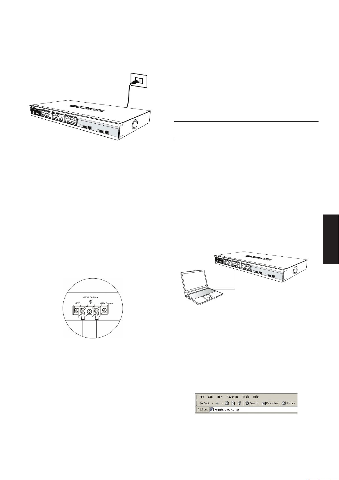
Etapa 3 – Conectando o Cabo de
Opções de Gerenciamento
Alimentação AC
Os usuários agora podem conectar o cabo de alimentação
CA a uma tomada (preferencialmente aterrada e com
proteção contra surtos) e na parte traseira do switch.
Figura 4. Conectando o switch a uma tomada
Queda de Energia
Por precaução, o switch deverá ser desplugado em caso
de queda de energia. Quando a energia voltar, conecte
novamente o switch.
Esse sistema pode ser gerenciado fora da banda por meio
da porta do console no painel frontal/traseiro ou na banda
utilizando-se Telnet. O usuário também pode selecionar o
gerenciamento baseado na web, que pode ser acessado
via a utilização de um navegador web. Cada Switch deve
ter seu próprio Endereço IP atribuído, que é utilizado para
comunicação com um gerenciador de rede SNMP ou
outra aplicação TCP/IP (por exemplo, BOOTP, TFTP). O
endereço IP padrão do Switch é 10.90.90.90. O usuário
pode alterar o endereço IP padrão do Switch para atender
a especicação de esquema de endereços de rede.
Interface de Gerenciamento Baseada na
Web
Após uma instalação física bem sucedida, você pode
congurar o Switch, monitorar o painel de LEDs e exibir
estatísticas gracamente utilizando um navegador web,
como o Netscape Navigator (versão 6.2 e superior) ou
Microsoft® Internet Explorer (versão 5.0 e superior).
Você necessita dos seguintes equipamentos para
começar a conguração web do seu dispositivo:
• Um PC com uma conexão Ethernet RJ-45
• Um cabo Ethernet padrão
Conectando a alimentação
CC ao Switch com suporte a
alimentação CC
Siga as instruções abaixo para conectar a fonte de
alimentação CC de um switch alimentado por corrente
contínua a uma fonte de alimentação CC.
Figura 5. Conexões de alimentação presa aos
contatos na unidade
Prenda rmemente os cabos CC aos contatos’negativos
e positivos na unidade de ação.
• O pólo negativo (-) conecta-se ao contato -48V.
• O pólo positivo (+) conecta-se ao contato -48V
Return.
• Caso disponível, o terra pode ser conectado ao pólo
de contato central.
• Aperte os parafusos de contato de tal maneira que a
conexão esteja rme.
Etapa 1
Conecte o cabo Ethernet a qualquer uma das portas no
painel frontal do switch e à porta Ethernet no PC.
Figura 6. Conectado a um nó nal via cabo Ethernet
Etapa 2
Para começar a gerenciar o seu Switch, abra o navegador
que você instalou no seu computador e digite o endereço
IP do seu dispositivo no formato http://xxx.xxx.xxx.xxx,
onde xxx é um número entre 1- 255. Para usuários que
desejam acessar o dispositivo pela primeira vez, insira o
endereço IP de fábrica 10.90.90.90, e pressione Enter.
Figura 7. Digite o endereço IP 10.90.90.90 no
navegador web.
PORTUGUÊS
27

Etapa 3
Isso abre a janela de autenticação do módulo de
gerenciamento, conforme mostrado abaixo.
Para conectar um terminal à porta do
console:
1. Conecte o conector fêmea do cabo RS-232
diretamente à porta do console no Switch, e aperte os
parafusos de retenção.
2. Conecte a outra extremidade do cabo a um terminal
ou ao conector serial de um computador executando
o software de emulação de terminal. Congure o
software de emulação de terminal conforme segue:
3. Selecione a porta serial apropriada (porta COM 1 ou
porta COM 2).
4. Dena a taxa de transferência de dados. (9600 ou
115200)
Figura 8. Entre na janela de Senha de Rede
Deixe tanto o campo de Nome do Usuário como de
Senha em branco e clique em OK. Isso vai abrir a
interface do usuário baseada na Web.
OBSERVAÇÃO: O endereço IP padrão
de fábrica do Switch é 10.90.90.90, com
máscara de sub-rede 255.0.0.0 e
gateway padrão 0.0.0.0.
Conectando a Porta do Console
(RS-232DCE)
O Switch oferece uma porta serial RS-232 serial que
possibilita a conexão a um computador ou terminal
PORTUGUÊS
para monitorar e congurar o Switch. Essa porta é um
conector DB-9 fêmea, implementado como uma conexão
de equipamento de terminal de comunicação de dados
(DCE).
Para utilizar a porta do console, você precisa dos
seguintes equipamentos:
• Um terminal ou computador com uma porta serial e a
capacidade de emular um terminal.
• Um modem nulo ou cabo RS-232 cruzado com um
conector DB-9 fêmea para a porta do console no
Switch.
5. Dena o formato d dados para 8 bits de dados, 1 bit
de parada e nenhuma paridade.
6. Dena o uxo de controle como nenhum.
7. Sob Propriedades, selecione VT100 como Modo de
emulação.
8. Selecione as teclas do Terminal para as teclas de
Função, Seta e CTRL. Certique-se de selecionar as
teclas do Terminal (e não as teclas do Windows).
9. Após congurar corretamente o terminal, conecte o
cabo de alimentação à entrada de energia na parte
traseira do Switch. A seqüência de boot aparece no
terminal.
10. Após a seqüência de boot ser concluída, a tela de
login do console é exibida.
11. Se você não entrou no programa de interface de
linha de comando (CLI), pressione a tecla Enter
quando for solicitado a inserir o Nome do Usuário
e Senha. Não há nome do usuário e senha padrão
para o Switch. O administrador deve primeiramente
criar nomes de usuários e senhas. Se você já
deniu contas de usuários, faça o login e continue
congurando o Switch.
12. Insira os comandos para concluir suas tarefas
desejadas. Muitos comandos exigem privilégios de
acesso no nível do administrador. Consulte o Manual
de Referência de Interface de Linha de Comando
no CD de documentação para uma lista de todos os
comandos e informações adicionais utilizando a CLI.
Figura 9. Conectado ao nó nal via o cabo do
console
28
13. Após concluir suas tarefas, saia da sessão sem o
comando logout ou feche o programa emulador.
Gerenciamento Telnet
Os usuários também podem acessar o console do
switch via Telnet utilizando o Prompt de Comando do
seu PC. Para acessá-lo no seu computador, os usuários
devem primeiro assegurar que uma conexão válida seja
estabelecida por meio da porta Ethernet do Switch e do
seu PC, e então clicar em Iniciar > Programas > Acessórios
> Prompt de comando no seu computador. Uma vez
que a janela do console abrir, digite o comando telnet
10.90.90.90 (dependendo do endereço IP congurado) e
pressione Enter no seu teclado. Você

deverá ser direcionado para a tela do console para a
Interface de Linha de Comando do Switch. Pressione a
tecla Enter nos prompts de Nome de Usuário e Senha.
Não há nome do usuário e senha padrão para o Switch.
Gerenciamento baseado em SNMP
Você pode gerenciar o Switch como o D-Link D-View ou
qualquer programa de console compatível com SNMP.
A função SNMP está Desabilitada por default para
switches gerenciados D-Link.
O Sistema de Gerenciamento de Rede SNMP D-View é
uma ferramenta de gerenciamento baseada em padrões
abrangente, projetada para gerenciar a rede crítica de
maneira centralizada. O D-View fornece ferramentas
úteis para possibilitar que os administradores gerenciem
congurações de dispositivos, tolerância a falhas,
desempenho e segurança com ecácia. A D-Link oferece
uma versão demo gratuita do D-View que lhe permite
avaliar gratuitamente os produtos por 30 dias. Você
pode baixar essa versão do site http://dview.dlink.com.
tw/support_Download_Trial_Version.asp
Informações Adicionais
Se você está enfrentando problemas na conguração
da sua rede, favor consultar o Guia do Usuário fornecido
com o switch. Ele contém muito mais regras, diagramas,
explicações e exemplos para ajudá-lo a colocar a sua
rede em operação.
Ajuda adicional está disponível por meio dos nossos
escritórios relacionados na parte traseira do Guia do
Usuário ou on-line. Para obter maiores informações sobre
os produtos da D-Link ou informações de marketing, favor
visitar o website http://www.dlink.com
PORTUGUÊS
Informações sobre a garantia
As informações sobre a Garantia Vitalícia Limitada da
D-Link estão disponíveis em http://warranty.dlink.com/
29

關於本指南
本指南提供了一步一步的指示,設立所有D-Link管理交換
機和相對保修,安全,法規,和環境的通知。
請注意您所購買的模型,可能會出現圖中所示的略有不
同。
欲了解更多有關您的交換機,其組成部分,網路連接和技
術規格的詳細信息,請參閱交換機內附的用戶指南。
圖 1. 黏貼橡膠墊
步驟 1 – 打開包裝
打開包裝盒並妥善取出內容物。請參閱使用指南內的包裝
內容清單,檢查項目是否缺漏或損壞。若有缺漏或損壞項
目,請洽當地 D Link 經銷商更換。
交換器內附配件對照表
交換器形式 *
項目
設備 Yes Yes Yes Yes
RS-232 Cable
(Printer cable)
機架拖座 No Yes Yes Yes
橡膠腳墊 Yes Yes Yes Yes
電源線
( 轉接器 )
中
文
使用手冊 Yes Yes Yes Yes
多國語言快速
安裝手冊
非網管型 智慧型或網管型
掌上型
No No Yes Yes
Yes Yes Yes Yes
Yes Yes Yes Yes
桌上型 /
機架式
機架安裝
本交換器可固定在 EIA 標準大小 19 英吋機架上,此機架
可置於纜線櫃中,與其他設備放在一起。若要安裝於機架
上,請將固定架裝在交換器的兩側面板 (一邊一個) 並以
內附的螺絲固定 (請注意,這些固定架無法供 palm size 的
交換器使用)。
模組式
圖 2. 裝上固定架
接著,請用機架設備提供的螺絲把交換器固定在機架上。
*可實體堆疊交換器需內附堆疊線。
步驟 2 – 安裝交換器
為確保交換器安裝與操作的安全,建議您:
•以肉眼檢查電源線是否完全插入 AC 電源插座。
•確保交換器的散熱與通風正常。
•勿將重物置於交換器上。
桌面或機板安裝
若要將交換器安裝在桌面或機板上,請將裝置內附的橡膠
墊黏貼在裝置的四個角落。請在裝置周圍預留適當通風空
間。
圖 3. 將交換器安裝在標準大小的設備機架上
步驟 3 – 插上 AC 電源線
現在請將 AC 電源線的一端插上電源插座 (最好是有接地
與電波脈衝防護的插座),另一端插在交換器後方。
圖 4. 將交換器插上電源插座
30

斷電
為保護裝置,在停電時請將電源線拔下,恢復供電時再插
回去。
將 DC 電源接在支援 DC 電源的交換
器上
請循以下步驟,將 DC 式交換器的 DC 電源線接上 DC 電
源。
圖 5. 將電源接頭接在螺絲上
圖 6. 用乙太網路纜線連接到一台端點裝置
步驟 2
開啟電腦上的瀏覽器,輸入本裝置的 IP 位址,格式為
http://xxx.xxx.xxx.xxx,其中 xxx 是 1-255 之間的數字。若
想快速存取本裝置,請輸入工廠預設 IP 10.90.90.90 再按
Enter 鍵。
將 DC 電源接牢在螺絲座的正電與負電接頭上。
• 負電 (-) 接到 -48V 接頭。
• 正電 (+) 接到 -48V Return 接頭。
• 若有接地線,請接到中間螺絲上。
• 鎖緊螺絲,確保連接牢固。
管理選項
本系統可透過前/後面板上的 console 埠進行 out-of-band
管理,或以Telnet 進行 in-band 管理。使用者亦可用瀏
覽器進行網頁式管理。每部交換器必須擁有自己的 IP 位
址,以和 SNMP 網路管理程式或其它 TCP/IP 應用程式 (
如 BOOTP 與 TFTP) 進行通訊。本交換器的預設 IP 位址
是 10.90.90.90。使用者可變更此預設 IP 位址,以符合您
的網路位址分配方式。
網頁式管理介面
硬體安裝完成後,便可設定交換器、監看 LED 面板,並
用瀏覽器顯示統計圖形。可採用 Netscape Navigator (6.2
或更新版本) 或 Microsoft® Internet Explorer (5.0 或更新版
本) 等瀏覽器。
圖 7. 在瀏覽器輸入 IP 位址 10.90.90.90
步驟 3
會出現管理模組的使用者認證視窗,如下圖所示。
中
文
圖 8. 輸入網路密碼視窗
請將 User Name 與 Password 欄位都保持空白並按 OK。
會出現網頁式使用介面。
若要進行網頁式設定,請準備以下裝置:
• 一台具備 RJ-45 乙太網路連線功能的個人電腦
• 一條標準的乙太網路纜線
步驟 1
將乙太網路纜線的一端接在交換器前端面板的任一個連接
埠,另一端接在個人電腦的乙太網路連接埠。
注意:交換器的出廠預設 IP 位址是
10.90.90.90,子網路遮罩是 255.0.0.0,
預設閘道器是 0.0.0.0。
31

連接 Console 埠 (RS-232 DCE)
Telnet 管理
本交換器含一個 RS-232 序列埠,可連接到電腦或終端
機上,進行交換器的監控與設定。此連接埠是 DB-9 母
接頭,以資料通訊終端設備 (data communication terminal
equipment,DCE) 連接方式實做。
若要使用 console 埠,請準備以下裝置:
•一台擁有序列埠,並具備終端機模擬功能的終端機或電
腦。
•null modem 或交叉式 RS-232 纜線,此纜線須含 DB-9
母接頭,供交換器的 console 埠使用。
圖 9. 透過 console 纜線連到一台端點裝置
您亦可用電腦的命令提示執行 Telnet 來存取交換器的
console。若要用電腦存取交換器,請先確定交換器的乙
太網路埠與電腦之間已建立了有效連線,然後在電腦上按
開始 > 所有程式 > 附屬應用程式 > 命令提示字元。出現
命令列視窗後,輸入指令 telnet 10.90.90.90 (依所設定的
IP 位址而定) 並按 Enter 鍵。您應該會看見交換器命令列
界面的起始 console 畫面。請在使用者名稱與密碼提示按
Enter 鍵。本交換器沒有預設使用者名稱與密碼。
SNMP 式管理
您可用 D-Link D-View 或任何與 SNMP 相容的 console 程
式管理本交換器。D-Link 網管型交換器的 SNMP 功能預
設是停用的。
D-View SNMP網路管理系統是一個全面的基於標準的管理
工具,旨在集中管理關鍵網路。D-View提供有用的工具,
允許網絡管理員有效地管理設備配置,容錯,性能和安全
性。 D-Link的提供免費的D-View試用版下載,讓您免費
評估30天的產品。你可以從這裡下載試用版: http://dview.
dlink.com.tw/support_Download_Trial_Version.asp
將終端機連到 console 埠:
1. 將 RS-232 纜線的母接頭直接插進交換器的 console
埠,並旋緊兩側螺絲。
2. 將纜線另一端接到終端機,或接到執行終端機模擬軟體
的電腦的序列埠上。請按以下方式設定終端機模擬軟
體:
3. 選擇適當的序列埠 (COM port 1 或 COM port 2)。
中
4. 設定資料傳輸率。
文
5. 設定資料格式為 8 資料位元、1 停止位元,沒有同位。
6. 將流程控制設為無。
7. 在內容中,將模擬模式設為 VT100。
8. 選擇功能、箭頭與 Ctrl 鍵的終端機按鍵。確定所選的是
終端機鍵,而不是 Windows 按鍵。
9. 終端機設定完成後,將電源線插入交換器後方的電源插
座。終端機會出現開機程序。
10.開機程序完成後,會出現 console 登入畫面。
11.若您尚未登入命令列介面 (CLI) 程式,請在使用者名稱
與密碼提示按 Enter 鍵。本交換器沒有預設使用者名稱
與密碼。管理員須先建立使用者名稱與密碼。若您已預
先設定了使用者帳戶,請登入並繼續設定交換器。
12.輸入指令來完成您所需要的工作。許多指令都需要管理
員權限才能執行。請參見文件 CD 上的 <命令列介面參
考手冊>,取得所有指令列表與CLI 的其他使用資訊。
13.工作完成後,請用登出指令或關閉模擬器程式來跳出階
段作業。
其他資訊
如果您設置網路時遇到問題,請參閱用戶指南。它包含有
更多的規則,圖表,解釋和例子來幫助你讓你的網路和運
行。
額外的幫助是可以透過用戶指南後面的服務據點與在線服
務。要知道更多關於D-Link的產品或營銷資訊,請訪問網
站: http://www.dlink.com
保固資訊
D-Link的有限終身保修資訊在:
http://warranty.dlink.com/
32

NOTES
中
文
33

Mengenai Petunjuk Pemasangan
Ini
Panduan ini memberikan petunjuk langkah-demi-langkah
mengenai cara mengatur semua switch managed D-Link
juga termasuk Garansi, Keselamatan, Peraturan, dan
Pemberitahuan Lingkungan.
Harap dicatat bahwa model yang telah Anda beli mungkin
terlihat sedikit berbeda dari yang ditunjukkan dalam
ilustrasi.
Untuk informasi lebih lanjut mengenai switch Anda
seperti, komponen, cara membuat koneksi jaringan dan
spesikasi teknis, silahkan lihat Panduan Pengguna yang
disertakan dengan switch Anda.
Langkah Pertama – Membuka
Paket
Buka kardus penjualan dan secara hati-hati keluarkan
semua isinya. Tolong lihat daftar isi yang ada pada
petunjuk penggunaan untuk memastikan semua item ada
dan tidak rusak. Jika ada item yang hilang atau rusak,
silahkan hubungi penjual untuk penggantian.
• Lakukan pengecekan langsung kabel power untuk
melihat apakah kabel power sudah terpasang dengan
benar ke colokan listrik.
• Pastikan ada ruang untuk pelepasan panas dan
ventilasi yang cukup disekitar switch.
• Jangan menaruh benda yang berat diatas switch.
Pemasangan di atas meja atau papan
Ketika memasang switch di atas meja atau papan,
kaki karet yang termasuk dalam paket penjualan harus
dipasang di switch pada setiap sudut bawah switch.
Berikan ruang yang cukup sebagai ventilasi disekitar
switch.
Gambar 1. Memasang kaki karet
Pemasangan pada Rak
Perangkat Ya Ya Ya Ya
Kabel RS-232
(Kabel Printer)
Braket untuk
pemasangan
Kaki Karet Ya Ya Ya Ya
Kabel Power
(Adapter)
Petunjuk
Penggunaan
Petunjuk
Pemasangan
Cepat multibahasa
BAHASA INDONESIA
Item-item yang terdapat dalam paket
penjualan switch
Tipe Switch*
Item
di rak
Unmanaged
Palm
No No Ya Ya
No Ya Ya Ya
Ya Ya Ya Ya
Ya Ya Ya Ya
Ya Ya Ya Ya
Desktop/Rack
Mount
Smart atau
Managed
Chassis
Switch dapat dipasang pada rak dengan ukuran standar
EIA 19 inci, dimana dapat ditempatkan pada ruang
komunikasi/server dengan perangkat lainnya. Untuk
memasang pada rack, pasang braket pada bagian samping
switch (satu braket di setiap sisi) dan kencangkan dengan
sekrup yang tersedia dalam paket penjualan (Catatan :
Braket ini tidak dirancang untuk Switch model Palm Size).
Gambar 2. Memasang Braket
Kemudian, gunakan sekrup yang terdapat dalam
penjualan rak untuk memasang switch ke rak.
*Switch stackable, tidak seperti switch standalone, akan
termasuk sebuah kabel cascade
Langkah 2 : Pemasangan Switch
Untuk pemasangan dan pengoperasian switch secara
aman, direkomendasikan anda:
34
Gambar 3. Memasang switch ke rak dengan ukuran
standar

Langkah 3: Colokkan kabel
Pilihan Manajemen
power AC
Sekarang anda dapat menghubungkan kabel power
AC ke port power dibelakang switch ke colokan listrik.
(Direkomendasikan peralatan sudah di grounded dan
dilengkapi dengan pelindung terhadap lonjakan listrik.
Gambar 4. Mencolokkan switch ke colokan listrik
Pemadaman Listrik
Sistem ini dapat di-atur melalui port console pada bagian
depan/belakang atau menggunakan Telnet. Pengguna
juga dalam memilih manajemen berbasiskan web yang
dapat diakses melalui web browser. Setiap switch harus
diberikan alamat IP sendiri, dimana digunakan untuk
komunikasi dengan Manager Jaringan SNMP atau
aplikasi TCP/IP lainnya (sebagai contoh BOOTP, TFTP).
Alamat IP default switch adalah 10.90.90.90. Pengguna
dapat mengganti alamat IP switch untuk menyamakan
dengan skema alamat jaringan anda.
Manajemen antarmuka berbasiskan Web
Setelah sukses memasang switch, anda dapat mengatur
switch, memantau panel LED dan melihat statistik secara
gras menggunakan web browser seperti Netscape
Navigator (versi 6.2 atau lebih tinggi) atau Microsoft®
Internet Explorer (versi 5.0 atau lebih tinggi).
Perangkat yang anda butuhkan untuk memulai
kongurasi web adalah:
• Sebuah komputer dengan koneksi Ethernet RJ-45
• Kabel Ethernet standar
Sebagai tindakan pencegahan, kabel power harus dicabut
jika terjadi pemadaman listrik. Ketika listrik kembali
menyala, anda dapat kembali menghubungkan switch ke
listrik.
Menghubungkan sumber listrik
DC ke Switch yang mendukung
sumber listrik DC
Ikuti instruksi berikut untuk menghubungkan power supply
DC dari Switch dengan sumber listrik DC ke sumber listrik
DC.
Gambar 5. Koneksi power terhubung ke konektor DC
Langkah 1
Hubungkan kabel Ethernet dengan port mana saja pada
bagian depan dari switch dan port Ethernet pada PC.
BAHASA INDONESIA
Gambar 6. Menghubungkan 2 perangkat melalui
kabel ethernet
Langkah 2
Untuk memulai mengatur switch anda, buka browser yang
ada pada komputer anda dan masukkan alamat IP dari
switch anda dengan format http://xxx.xxx.xxx.xxx dimana
xxx adalah angka antara 1-255. Untuk pengguna yang
mengakses switch untuk pertama kali-nya, masukkan
alamat IP default yaitu 10.90.90.90 dan tekan Enter.
Hubungkan secara hati-hati power DC ke konektorpositif
dan negative dari sumber DC.
• Kutub negatif terhubung ke konektor -48V.
• Kutub postif terhubung ke konektor -48V Return.
• Jika tersedia, grounding bumi boleh dihubungkan ke
konektor di tengah.
• Kencangkan baut konektor sehingga koneksi aman.
Gambar 7. Masukkan alamat IP 10.90.90.90 pada web
browser
35
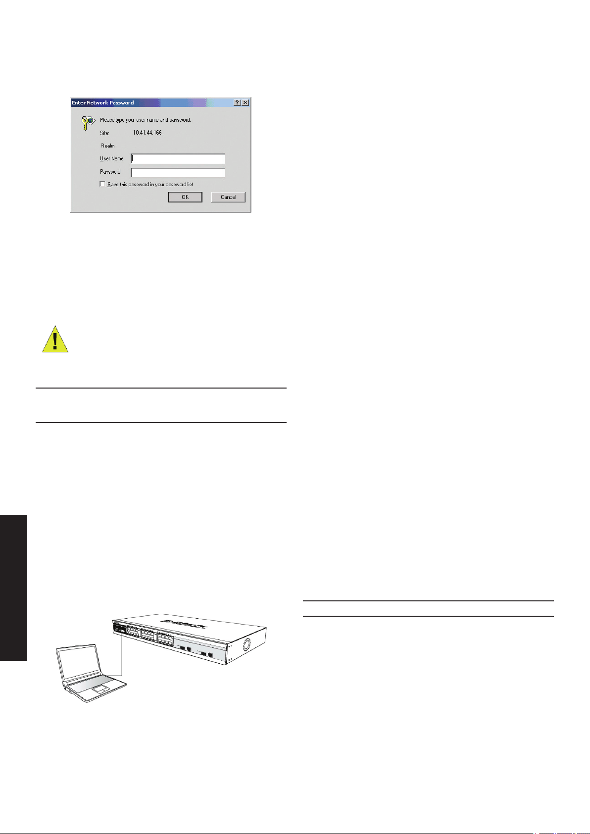
Langkah 3
Ini akan membukan jendela autentikasi user seperti yang
terlihat dibawah.
Gambar 8. Memasuki jendela autentikasi password
Biarkan User Name dan Password dalam keadaan
kosong dan klik OK. Ini akan membuka antar muka
pengguna berbasiskan web.
Catatan : Alamat IP default
adalah 10.90.90.90 dengan
subnet mask 255.0.0.0 dan
default gateway 0.0.0.0.
Untuk menghubungkan sebuah terminal
dengan port console:
1. Hubungkan konektor female dari kabel RS-232
secara langsung ke port console pada Switch dan
kencangkan baut-nya
2. Hubungkan ujung satunya lagi dengan konektor serial
yang ada pada sebuah komputer yang menjalan
program terminal emulation. Atur program terminal
emulation itu sebagai berikut :
3. Pilih port serial yang digunakan (port COM 1 atau
COM 2)
4. Atur data rate (9600 atau 115200)
5. Atur data format ke 8 data bits, 1 stop bit dan no parity
6. Atur ow control ke none
7. Pada bagian Properties, piliha VT100 sebagai mode
emulation
8. Pilih Terminal keys untuk Function, Arrow dan Ctrl
Keys. Pastikan anda memilih Terminal keys (bukan
Windows keys)
9. Setelah anda mengatur terminal dengan benar, colok
kabel power dan proses boot akan muncul di terminal
10.Setelah proses boot selesai maka layar login console
akan muncul
Menghubungkan port Console
(RS-232 DCE)
Switch menyediakan port serial RS-232 yang
memungkinkan koneksi antara sebuah komputer atau
terminal untuk memonitor dan mengatur switch. Port ini
adalah konektor female DB-9 yang diimplementasikan
sebagai koneksi DCE (Data Communication Terminal
Equipment).
Untuk menggunakan port console, anda butuh perangkat
sebagai berikut:
• Sebuah terminal atau komputer dengan port serial dan
mampu utk membuat sebuah terminal.
• Null Modem atau kabel crossover RS-232 dengan
konektor female DB-9 untuk port console pada switch.
BAHASA INDONESIA
Gambar 9. Menghubungkan 2 perangkat melalui
kabel console
11.Jika anda belum login ke program CLI maka tekan
Enter pada bagian User Name dan Password.
Tidak ada user name dan password default-nya.
Administrator pertama-tama harus membuat user
names dan password. Jika anda sudah membuat
akun pengguna sebelumnya, login dan lanjutkan untuk
mengatur switch
12.Masukkan perintah untuk mengatur fungsi yang
anda inginkan. Banyak perintah yang membutuhkan
level akses administrator. Lihat pada Petunjuk
Penggunaan Command Line Interface yang ada pada
CD dokumentasi untuk melihat semua perintah dan
informasi yang dibutuhkan dalam menggunakan CLI
13.Ketika anda menyelesaikan perintah-perintah yang
dibutuhkan, keluar dari sesi dengan perintah logout
atau tutup program emulator.
Manajemen Telnet
Pengguna bisa mengakses console switch melalui Telnet
dari Command Prompt PC anda. Untuk mengakses dari
komputer anda, pengguna harus memastikan koneksi
antara Switch dan PC anda, kemudian klik Start > Programs
> Accessories > Command Prompt pada komputer anda.
Setelah jendela command prompt terbuka, ketik telnet
10.90.90.90 (alamat IP tergantung alamat IP anda) dan
tekan Enter pada keyboard anda. Anda akan diantar ke
layar pembuka console command line interface dan tekan
Enter untuk User Name dan Password. Tidak ada user
name dan password default untuk Switch.
36

Manajemen berbasiskan SNMP
Anda dapat mengatur switch dari D-Link D-View atau
program SNMP lainnya. Fungsi SNMP secara default
dinon-aktifkan untuk semua Switch Manage D-Link.
D-View SNMP Network Management System adalah alat
manajemen standar komprehensif yang dirancang untuk
mengelola jaringan kritis anda secara terpusat. D-View
menyediakan alat yang berguna untuk memungkinkan
administrator jaringan secara efektif mengelola
kongurasi perangkat, toleransi kesalahan, kinerja dan
keamanan. D-Link menawarkan D-View versi trial yang
memungkinkan Anda dengan bebas mengevaluasi produk
selama 30 hari. Anda dapat mendownload versi trial dari
situs ini http://dview.dlink.com.tw/support_Download_
Trial_Version.asp
Informasi Tambahan
Jika Anda mengalami masalah dalam mengatur jaringan
Anda, silakan lihat Panduan Pengguna yang termasuk
dalam kemasan switch. Panduan ini berisi banyak
pengaturan, penjelasan grak dan contoh-contoh yang
dapat membantu Anda membuat jaringan Anda berjalan
dengan baik.
Bantuan tambahan tersedia melalui kantor-kantor kami
yang tertera di bagian belakang Panduan Pengguna.
Untuk mengetahui lebih lanjut mengenai produk D-Link
atau mengenai informasi pemasaran, silakan kunjungi
situs web http://www.dlink.com
Informasi Jaminan
Informasi Garansi Lifetime Terbatas D-Link tersedia di
http://warranty.dlink.com/
BAHASA INDONESIA
37

本書の内容
平置きおよび棚などへの設置
この冊子は、すべてのD-Linkマネージメントスイッチの設置及び
関連する保証、安全、規制、環境に関して段階的に記載した説
明書です。図に示されたものがご購入頂いたモデルと異なる
場合がありますので予めご了承ください。
スイッチ、コンポーネント、ネットワーク接続、技術的なスペックに
ついてより詳細な情報を確認するには、スイッチに同梱されて
いるユーザガイドを参照してください。
1 - 箱を開ける
梱包を開けて、中身をていねいに取り出します。ユーザマニュア
ルの付属品一覧を見て、同梱物がすべてそろっているか確認
してください。万一不足している部品や破損している部品があ
りましたら、弊社ホームページにてユーザ登録を行い、サポート
窓口までご連絡ください。
スイッチ製品パッケージ内容
スイッチタイプ
アンマネージドスマート / マネ
ージド
アイテム
小型タ
イプ
デバイス ○ ○ ○ ○
RS-232
シリアルケー
ブル
ラックマウン
トキット
× × ○ ○
× ○ ○ ○
デスクトップ
/ ラッ
クマウントタ
イプ
シャー
シ
タイプ
平置き及び棚などに設置する場合は、付属のゴム足を本体
底面の四隅に取り付けます。スイッチの周囲には通気のため
に十分なスペースを確保し設置してください。
図1 ゴム足を取り付ける
ラックに設置するとき
本製品はEIA 規格19 インチラックに取り付けることができま
す。サーバルームなどに設置する場合に便利です。はじめに、
ラックマウントキットを付属のネジで本製品の両側面に取り付
けます。(ラックマウントキットはコンパクトタイプのスイッチに は
使えませんのでご注意ください。 )
図2 ラックマウントキットを取り付ける
次に、付属のネジを使用して、スイッチをラックに固定します。
ゴム足 ○ ○ ○ ○
電源コード
( アダプタ )
ユーザガイド ○ ○ ○ ○
多言語 QIG ○ ○ ○ ○
○ ○ ○ ○
2 - 設置
日本語
安全にお使いいただくために、以下の点にご注意ください。
• 電源ケーブルを本体の電源コネクタに確実に差し込んでく
ださい。
• 本製品の周囲には、放熱と通気のために十分なスペースを
確保してください。
• 本製品の上に重たいものを置かないでください。
38
図3 スイッチをラックに取り付ける

3 - 電源ケーブルの接続
管理方法
電源ケーブルを本体背面の電源コネクタに接続し、もう一方
をコンセントに差し込みます。(コンセントはアース付きでサー ジ
対策のあるものをおすすめします。)
図4 電源ケーブルの接続
停電の際には
停電の際には念のためコンセントを抜きます。電力が復旧し て
から再度コンセントをつないでください。
本製品は、本体前面または背面のコンソールポート経由もしく
は、ネットワークを利用したTelnet接続を利用して管理すること
ができます。 さらに、Webブラウザを利用しての管理も可能で
す。SNMPネットワーク管理ツールや、BOOTP、TFTPといった他
のTCP/IPアプリケーションによる通信のため、それぞれのスイ
ッチに固有のIPアドレスを割り当てる必要があります。IPアドレス
の初期値は10.90.90.90です。お使いのネットワークのアドレスの
設定にあわせて変更してください。
Web ベース管理インターフェイス
Webブラウザを使って、スイッチの設定、ステータスLEDのモ
ニタリング、統計情報のグラフ表示などができます。使用可
能なブラウザは、Netscape Navigator(バージョン6.2以降)や
Microsoft® Internet Explorer(バージョン5.0以降)などです。
Web ブラウザを使ったスイッチの設定には、以下のものが必要
です。
• イーサネットポート(RJ-45)を持つコンピュータ
• 標準的なイーサネットケーブル
DC 電源をつなぐ(DC 電源対応スイッ
チのみ)
DC 電源対応のスイッチにDC 電源をつなぐ場合は、以下に
従ってください。
図5 DC 電源をつなぐ
DC 電源を接続部のプラス端子とマイナス端子につなぐ
• 電源のマイナス端子は、-48V 端子に接続します。
• 電源のプラス端子は、-48V Return 端子に接続します。
• 電源にアース端子がある場合は、中央の端子に接続しま
す。
• 接続を確実にするため、端子のネジをしっかりしめてくださ
い。
ステップ1
イーサネットケーブルを使って、スイッチ前面のいずれかのポー
トとコンピュータのイーサネットポートを接続します。
図6 イーサネットケーブルの接続
ステップ2
Web ブラウザを起動して、接続するするスイッチのIP アドレス
を入力します。入力の形式は「http://xxx.xxx.xxx.xxx」です
(xxx は1 から255 までの数字)。最初にスイッチにアクセスす
るときは、初期値の「10.90.90.90」を入力し、Enter キーを押し
ます。
日本語
図7 Web ブラウザにIP アドレス「10.90.90.90」を入力
39

ステップ3
端末をコンソールポートに接続するには
IPアドレスを入力してEnterを押すと、以下のようなユーザ認証
画面が表示されます。
図8 ユーザ認証画面
「User Name」と「Password」には何も入力せずに「OK」をクリッ
クします。OKをクリックするとWebベース管理インターフェイス
が起動します。
初期設定値は以下のとおりです。
IP アドレス: 10.90.90.90
サブネットマスク: 255.0.0.0
ゲートウェイ: 0.0.0.0
1. RS-232ケーブルを本製品のコンソールポート(RS-232端子)
に接続し、コネクタのネジをしめる。
2. ケーブルのもう一方を、ターミナルまたはターミナルエミュ
レーションソフト(以下ターミナル)の動作しているコンピュー
タに接続する。手順3~8でターミナルの通信設定を行いま
す。
3. 適切なシリアルポート(COMポート1または2)を選ぶ。
4. データ転送レートを設定する。(9600または115200)
5. データ形式を、「データビット8」、「ストップビット1」、「パリティ
なし」、に設定する。
6. フロー制御を「なし」に設定する。
7. プロパティでエミュレーションモードをVT100にする。
8. 「ファンクションキー、方向キー、Ctrlキーの使い方」を「ターミ
ナルキー」に設定する。(「Windowsキー」を選ばないよう注
意してください)
9. ターミナルの通信設定後、本製品に電源ケーブルをつなぐ。
ターミナルに起動シーケンスが表示されます。
10. 起動終了後、ログインコンソールが表示されます。
11. コマンドラインインターフェイスを持つプログラムにログイン
していない場合は、UserNameとPassWordのプロンプトで
Enterキーを押す。本製品にはユーザ名とパスワードの初期
設定はされていないので、はじめにユーザ名とパスワードの
設定をする必要があります。すでにユーザアカウントが設定
されている場合は、ログインしてスイッチの設定を続けます。
コンソールポート接続 (RS-232 DCE)
本製品のRS-232端子にコンピュータやターミナルを接続し、
スイッチのモニタリングや設定をすることができます。本製品
のRS-232 端子はメス型のD-sub 9ピンコネクタで、DCE(data
communication terminal equipment)接続に対応しています。
コンソールポートを利用するには、以下が必要です。
• シリアルポートを持ち、コンソールに接続できるコンピュータ
• メス型のD-sub 9ピンコネクタに対応したRS-232クロスケー
ブル
日本語
図9 コンソールポートを利用した接続
12. 必要なコマンドを入力して、スイッチの設定をする。多くの
場合、設定には管理者レベルのアクセス権限が必要です。
コマンド一覧などの情報については、ユーザマニュアルCDに
収録された『コマンドラインインターフェイスリファレンスマニュ
アル』をご覧ください。
13. 設定後、ログアウトするか、エミュレーションプログラムを終
了して、接続を終了する。
Telnet を使った管理
Telnet 経由で、コンピュータのコマンドプロンプトを使ってスイッ
チコンソールにアクセスすることができます。
はじめに、本製品のイーサネットポートとコンピュータの接続を確
認してください。次に、コンピュータで「スタート」-「プログラム」-「
アクセサリ」-「コマンドプロンプト」をクリックします。
コマンドプロンプトのウインドウが表示されたら、
「telnet10.90.90.90」(IP アドレスは設定によって変わります)と
入力してEnter キーを押します。
スイッチのコマンドラインインターフェイスの初期画面が表示さ
れますので、UserName と PassWord のプロンプトでEnterキー
を押します。本製品にはユーザ名とパスワードの初期設定はさ
れていません。
40

SNMP による管理
D-Link D-ViewなどのSNMP対応のマネージメントソフトウェアで
本製品を管理することができます。D-Linkマネジメントスイッチ
の初期設定ではSNMP機能はオフになっています。
D-View SNMPネットワーク管理システムはクリティカルなネット
ワークを集中的に管理するためにデザインされた総合的な標
準準拠の管理ツールです。D-Viewはデバイス設定、フォルトト
レランス、パフォーマンス、セキュリティをネットワーク管理者が
効果的に管理するために役立つツールです。D-Linkは製品評
価のために30日間無料で利用することのできるD-Viewトライ
アルバージョンを提供しています。トライアルバージョンは下記
からダウンロードすることができます。
http://dview.dlink.com.tw/support_Download_Trial_Version.
asp
追加情報
ネットワーク設定で問題が生じた場合は、スイッチに同梱され
ているユーザガイドを参照してください。ユーザガイドは、多くの
ルール、図、説明、例を含んでおり、ネットワークを構築・運用す
るのに役立ちます。
ユーザガイドの最後もしくは、オンラインで記載されている
D-Linkの各オフィスを通して更なるサポートを受けることができ
ます。D-Link製品やマーケティング情報についてより詳しく知り
たい場合は、下記のWebサイトをご確認ください。
http://www.dlink.com
保証情報
D-Linkリミテッドライフタイム保証情報については、下記をご覧
ください。
http://warranty.dlink.com/
日本語
41

關于快速安裝指南
桌面或板架安裝
本嚮導提供指示說明用來一步一步安裝所有的D-Link網管
交換機及相關保修、安全、法規和環境等注意事項。請注
意您所購買的產品可能會與文件中顯示的圖有細微的差
別。
更多關于您的交換機詳細信息、配件、設定網絡連接與技
術規格,請參閱產品包裝中的用戶手冊。
步驟1 - 開箱
打開包裝箱,小心取出裏面的物件。請按照用戶指南中的
裝箱清單清點所有物件,確認所有物品完好無損。如果有
任何物品缺失或損壞,請聯繫當地的D-Link經銷商予以更
換。
交換機包裝箱內所含物品
交換機類型
非網管類
物件
設備 有 有 有 有
交換機
掌上型
桌面 /
機架安裝
*
簡單網管或全網
管類交換機
机箱式
如要在桌面或板架上安裝交換機,必須先在設備底部四角
上裝上橡膠腳墊。注意在設備及四周物體之間流出足夠的
通風散熱空間。
圖 1. 裝上橡膠腳墊
機架安裝
交換機可以安裝到EIA標準19吋機架上,機架可以與其他
設備一起放置到配線櫃中。如要安裝,先將機架挂耳裝到
交換機的側面板上(一邊一個),然後用附帶的螺絲釘固定
(請注意這些挂耳不適用于掌上型的交換機)。
RS-232 線纜缆 无 无 有 有
機架挂耳 无 有 有 有
橡膠腳墊 有 有 有 有
電源線
( 適配器 )
用戶手冊 有 有 Yes 有
多語言版本快速安
裝手冊
*可堆叠交換機與獨立型交換機不同,應該包含一根堆叠線纜。
**
有 有 Yes 有
有 有 Yes 有
步驟 2 - 安裝交換機
如要安全地安裝和使用交換機,建議您按照以下方式操
作:
‧查看電源綫,確認其與交流電源接頭能完全配合使用。
‧確認交換機四周有足夠的空間保證散熱正常。
‧不要在交換機上放置重物。
圖2. 安裝機架挂耳
然後,使用設備機架附帶的螺釘將交換機安裝到機架上。
圖 3. 將交換機安裝到標準尺寸的設備機架中
簡中
42

步驟 3 - 插上交流電源線
管理選項
現在用戶需要將交流電源線插入電源插座(比較理想的插
座有接地和穩壓保護),另一端插入交換機的背板。
圖 4. 將交換機的電源線插入電源插座
電源故障
作為一項預防措施,在出現電源故障時應該拔掉交換機的
電源線。當供電恢復正常後再重新插上電源線。
通過前後面板上的Console接口,可對系統進行帶外管
理;或是通過Telnet的方式進行帶內管理。用戶也可以選
擇通過基于Web的管理方式,通過Web瀏覽器進行管理。每
個交換機必須分配一個自有IP地址,用于和SNMP網絡管理
器或其他TCP/IP應用程序(如BOOTP、TFTP)進行通信。交
換機的默認IP地址是:10.90.90.90。用戶可以根據自己
的網絡地址配置需要更改交換機的默認IP地址。
基于Web的管理界面
在成功地完成了物理安裝後,您可以配置交換機,監控
LED面板,並且通過如Netscape Navigator (6.2或更高版
本)或微軟的Internet Explorer (5.0或更高版本)的Web
瀏覽器顯示圖形化的統計數據
如要對設備進行Web配置,您需要如下附件:
‧ 有RJ-45以太網綫連接的計算機
‧ 一根標準的以太網線
步驟 1
為支持直流電源的交換機接入直流
電源
依照以下步驟,將直流電源供電的交換機連接到直流電源
上。
圖 5. 將電源接點連接到電源組的觸點上
將直流電源的正負極固定在配線組上。
‧ 將負極接點(-)接到-48V的觸點上。
‧ 將正極接點(+)接到-48V Return觸點上。
‧ 如果有接地線,將接地線連接到中間的觸點上。
‧ 將觸點的螺絲擰緊,確保連接可靠。
將以太網綫一端接入交換機前面板的任何一個端口,然後
將另一端接入計算機上的以太網端口。
圖 6. 通過以太網線連接PC
步驟 2
如要開始管理您的交換機,請打開安裝好的瀏覽器,然後
輸入設備的IP地址,格式缆http://xxx.xxx.xxx.xxx,這
裏xxx是介于1-255之間的數字。用戶如要在第一時間訪
問設備,輸入出廠默認IP地址10.90.90.90,然後按回車
鍵。
圖 7. 在瀏覽器中輸入IP地址10.90.90.90
簡中
43

步驟 3
將終端設備連接到Console端口:
隨後打開管理模塊的用戶驗證窗口,如下所示:
圖 8. 輸入網絡密碼窗口
用戶名和密碼欄都留空,然後點擊OK,打開基于Web的用
戶界面。
注意:交換機的出廠默認IP地址是
10.90.90.90,子網掩碼缆
255.0.0.0,默認網關是0.0.0.0。
連接Console端口(RS-232 DCE)
1. 將RS-232線纜的凹端接頭直接接入交換機的Console端
口,然後擰緊固定螺絲。
2. 將線纜的另一端連接到終端設備或運行終端仿真程序
的計算機的 串 行端 口。 按以下步驟設 置 終端 仿真 程
序:
3. 選擇正確的串行端口(COM1端口或COM2端口)。
4. 設置波特率(9600或115200)。
5. 數據格式設置為數據位8,停止位1,無奇偶校驗。
6. 數據流控制設置為無。
7. 設置好參數後,仿真類型選擇VT100。
8. 選擇啟動終端的密鑰方式為功能鍵+方向鍵和Ctrl鍵,
確認您選擇了終端密鑰(不是Windows密鑰)。
9. 在正確設置好終端後,將電源線插入交換機背板上的
電源插座上,在終端上即顯示啟動步驟。
10. 當啟動完成後,會顯示Console登錄界面。
11. 如果您未曾登錄過命令行界面(CLI)程序,在用戶和
密碼提示處按回車鍵。交換機沒有默認的用戶名和密
碼,首先需要創建一個管理員用戶名和密碼。如果您
已經創建了用戶賬號,登錄後繼續配置交換機即可。
交換機提供了一個RS-232串行端口,可以連接計算機或終
端設備,對交換機進行監控和配置。該端口是一個內凹的
DB-9針接頭,可執行與數據通信設備(DCE)的連接。如要
使用Console端口,您需要以下設備:
‧一台終端設備,或是一台帶有串行端口和可模擬終端的
計算機。
‧一個空閑的調制解調器或帶DB-9接頭的RS-232交叉線,
連接到交換機的Console端口。
圖 9. 通過配置綫纜連接PC
12. 輸入命令來完成所需的任務。多數命令需要管理員級
別的訪問權限。請參考文檔光盤中的命令行界面參考
手冊,查看所有命令的列表和有關使用CLI的其他信
息。
13. 當您完成任務後,可通過登出命令或關閉仿真程序來
退出會話。
Telnet管理
用戶也可以通過計算機的命令提示符界面,使用Telnet
訪問交換機的Console。在通過計算機訪問交換機之前,
用戶需要首先確認交換機和計算機之間已經建立了有效
的以太網連接,然後點擊計算機上的開始 > 程序 > 附
件> 命令提示符。當Console窗口打開時,輸入命令
telnet10.90.90.90 (根據所配置的IP地址),然後按回車
鍵,之後即可打開交換機命令行界面的Console窗口,在
用戶名和密碼提示處按回車鍵,此處交換機沒有默認的用
戶名和密碼。
基于SNMP的管理
您可以通過D-Link D-View或任何符合SNMP標準的網管程
序來管理交換機。D-Link網管交換機的SNMP功能在缺省狀
簡中
態下為關閉,請特別留意。
44

D-View SNMP網絡管理系統是一個全面的基于標準的管理
工具,旨在集中管理關鍵網絡。D-View提供易于使用的工
具以允許網絡管理員有效地管理設置配置、容錯、性能
和安全性。D-Link 提供免費的D-View試用版下載,允許
您免費試用評估產品30天。您可以通過以下鏈接下載試
用版http://dview.dlink.com.tw/support_Download_Trial_
Version.asp
其他信息
如果在網絡設置時遇到問題,請參考交換機附帶的用戶手
冊。手冊裏包括更多的規則、圖表、解釋和舉例,可以幫
助您進行網絡連接及正常運行。
更多幫助可查看用戶指南背後的技術服務電話或在綫詢問
技術服務人員。欲瞭解更多的D-Link產品或市場信息,請
訪問以下網頁http://www.dlink.com。
保修信息
D-Link保修信息請訪問以下網頁http://warranty.dlink.com/。
45
簡中

FCC Warning
This equipment has been tested and found to comply with the limits
for a Class A digital device, pursuant to Part 15 of the FCC Rules.
These limits are designed to provide reasonable protection against
harmful interference when the equipment is operated in a commercial
environment. This equipment generates, uses, and can radiate radio
frequency energy and, if not installed and used in accordance with
this manual, may cause harmful interference to radio communications.
Operation of this equipment in a residential area is likely to cause
harmful interference in which case the user will be required to correct
the interference at his own expense.
CE Mark Warning
This is a Class A product. In a domestic environment, this product may
cause radio interference in which case the user may be required to
take adequate measures.
Warnung!
Dies ist ein Produkt der Klasse A. Im Wohnbereich kann dieses Produkt
Funkstoerungen verursachen. In diesem Fall kann vom Benutzer
verlangt werden, angemessene Massnahmen zu ergreifen.
Precaución!
Este es un producto de Clase A. En un entorno doméstico, puede
causar interferencias de radio, en cuyo case, puede requerirse al
usuario para que adopte las medidas adecuadas.
Attention!
Ceci est un produit de classe A. Dans un environnement domestique,
ce produit pourrait causer des interférences radio, auquel cas
l`utilisateur devrait prendre les mesures adéquates.
Attenzione!
Il presente prodotto appartiene alla classe A. Se utilizzato in ambiente
domestico il prodotto può causare interferenze radio, nel cui caso è
possibile che l`utente debba assumere provvedimenti adeguati.
VCCI Warning
この装置は、クラスA情報技術装置です。この装置を家庭環境で使用す
ると電波妨害を引き起こすことがあります。この場合には使用者が適
切な 対策を講ずるよう要求されることがあります。VCCI-A
警告使用者:
這是甲類的資訊產品,在居住的環境中使用時,可能會造成射頻干擾,
在這種情況下,使用者會被要求採取某些適當的對策。
SFP (Mini-GBIC), XENPAK, and XFP Regulatory
Compliance
Networks pluggable optical modules meet the following regulatory
requirements:
• Class 1 Laser Product
• EN60825-1+A2:2001 or later, European laser standard
• FCC 21 CFR Chapter 1, Subchapter J in accordance with FDA &
CDRH requirements
Warranty Information
The D-Link Limited Lifetime Warranty information is available at http://
warranty.dlink.com/
SAFETY INSTRUCTIONS
Please adhere to the following safety guidelines to help ensure your
own personal safety and protect your system from potential damage.
Any acts taken that are inconsistent with ordinary use of the product,
including improper testing, etc., and those not expressly approved by
D-Link may result in the loss of product warranty.
Unless expressly approved by an authorized representative of D-Link in
writing, you may not and may not permit others to:
• Disassemble or reverse engineer the device or attempt to derive
source code (underlying ideas, algorithms, or structure) from the
device or from any other information provided by
D-Link, except to the extent that this restriction is expressly
prohibited by local law.
• Modify or alter the device.
• Remove from the device any product identification or other
notices, including copyright notices and patent markings, if any.
To reduce the risk of bodily injury, electrical shock, re, and damage to
the device and other equipment, observe the following precautions:
Power Sources
• Observe and follow service markings.
• Do not push any objects into the openings of your device unless
consistent with the authorized operation of the device. Doing so
can cause a fire or an electrical shock by shorting out interior
components.
• T h e po w e r i n g of this device must adhere to th e po w e r
specications indicated for this product.
• Do not overload wall outlets and/or extension cords as this will
increase the risk of re or electrical shock.
• Do not rest anything on the power cord or on the device (unless
the device is made and expressly approved as suitable for
stacking).
• Position system cables and power cables carefully; route cables
so that they cannot be stepped on or tripped over. Be sure that
nothing rests on any cables.
• Operate the device only from the type of external power source
indicated on the electrical ratings label.
• To help avoid damaging your device, be sure the voltage selection
switch (if provided) on the power supply is set to match the power
available at your location.
• Also be sure that attached devices are electrically rated to
operate with the power available in your location.
• Use only approved power cable(s). If you have not been provided
a power cable for your device or for any AC-powered option
intended for your device, purchase a power cable that is approved
for use in your country and is suitable for use with your device.
The power cable must be rated for the device and for the voltage
and current marked on the device’s electrical ratings label. The
voltage and current rating of the cable should be greater than the
ratings marked on the device.
• To help prevent an electrical shock, plug the device and peripheral
power cables into properly grounded electrical outlets. These
cables are equipped with three-prong plugs to help ensure proper
grounding. Do not use adapter plugs or remove the grounding
prong from a cable. If you must use an extension cable, use a
3-wire cable with properly grounded plugs.
• Observe extension cable and power strip ratings. Ensure that
the total ampere rating of all products plugged into the extension
cable or power strip does not exceed 80 percent of the ampere
ratings limit for the extension cable or power strip.
• To help protect your device from sudden, transient increases
and decreases in electrical power, use a surge suppressor, line
conditioner, or uninterruptible power supply (UPS).
• Do n ot modi fy power cables or p lugs. Consult a lice nsed
electrician or your power company for site modications. Always
follow your local/national wiring rules.
• When connecting or disconnecting power to hot-pluggable
power supplies, if offered with your device, observe the following
guidelines:
• Install the power supply before connecting the power cable to the
power supply.
• Unplug the power cable before removing the power supply.
• If the system has multiple sources of power, disconnect power
from the device by unplugging all power cables from the power
supplies.
46

Servicing/Disassembling
• Do not service any product except as expressly set forth in your
system documentation.
• Opening or removing covers that are marked with the triangular
symbol with a lightning bolt may expose you to an electrical
sh ock. O nly a trai ned service tech nician shou ld ser vice
components inside these compartments.
• To reduce the risk of electrical shock, never disassemble this
device. None of its internal parts are user-replaceable; therefore,
there is no reason to access the interior.
• Do not spill food or liquids on your system components, and
never operate the device in a wet environment. If the device gets
wet, see the appropriate section in your troubleshooting guide or
contact your trained service provider.
• Use the device only with approved equipment.
• Move products with care; ensure that all casters and/or stabilizers
are firmly connected to the system. Avoid sudden stops and
uneven surfaces.
Environment
• Do not use this device near water (e.g. near a bathtub, sink,
laundry tub, fish tank, in a wet basement or near a swimming
pool).
• Do not use this device in areas with high humidity.
• This device must not be subjected to water or condensation.
• Keep your device away from radiators and heat sources. Also, do
not block cooling vents.
Cleaning
• Always unplug the power before cleaning this device.
• Do not use liquid or aerosol cleaners of any kind. Use only
compressed air that is recommended for electronic devices.
• Use a dry cloth for cleaning.
PROTECTING AGAINST ELECTROSTATIC
DISCHARGE
Static electricity can harm delicate components inside your system.
To prevent static damage, discharge static electricity from your body
before you touch any of the electronic components, such as the
microprocessor. You can do so by periodically touching an unpainted
metal surface on the chassis.
You can also take the following steps to help prevent damage from
electrostatic discharge (ESD):
1. When unpacking a static-sensitive component from its shipping
carton, do not remove the component from the antistatic packing
material until you are ready to install the component in your
system. Just before unwrapping the antistatic packaging, be sure
to discharge static electricity from your body.
2. When transporting a sensitive component, first place it in an
antistatic container or packaging.
3. Handle all sensitive components in a static-safe area. If possible,
use antistatic floor pads, workbench pads, and an antistatic
grounding strap.
INSTRUCCIONES DE SEGURIDAD
Por favor siga las siguientes instrucciones de seguridad para garantizar
su propia seguridad personal y proteger el equipo de posibles daños.
Cualquier acto realizado que sea incompatible con el uso normal del
producto, incluyendo pruebas no apropiadas, etc., y aquellos que no estén
expresamente autorizados por D-Link pueden dar lugar a la pérdida de la
garantía del producto.
A menos que estén expresamente aprobados por escrito por un
representante autorizado de D-Link, usted no puede no puede:
• Desmontar o alterar el diseño del dispositivo o intentar obtener
el código fuente (ideas subyacentes, algoritmos, o estructura del
mismo) del dispositivo o de cualquier otra información proporcionada
por D-Link, salvo en el caso en que esta restricción esté
expresamente prohibida por la ley local.
• Modicar o alterar el dispositivo.
• Retirar la identicación del producto u otras noticaciones, incluyendo
las noticaciones de copyright y marcado de patente, si fuera el caso.
Para reducir el riesgo de lesiones personales, descargas eléctricas,
incendios y daños al aparato y otro equipamiento, tome las siguientes
precauciones:
Fuentes de alimentación
• Lea y siga atentamente las instrucciones de uso.
• No introduzca ningún objeto en las aberturas de su dispositivo. Si lo
hace, puede provocar un incendio o recibir una descarga eléctrica
debido a un cortocircuito de los componentes internos.
• El suministro eléctrico debe cumplir con las especicaciones de
alimentación indicadas para este producto.
• No sobrecargue los enchufes de pared y / o cables de extensión ya
que esto aumentará el riesgo de producir un incendio o recibir una
descarga eléctrica.
• No apoye nada sobre el cable de alimentación o encima el dispositivo
(a menos que el dispositivo esté diseñado y expresamente aprobado
para ello).
• Coloque los cables del equipo y de la fuente de alimentación con
cuidado, de forma que no se puedan pisar o tropezar fácilmente con
ellos. Asegúrese de que no apoya nada sobre los cables.
• Utilice el dispositivo sólo con una fuente de alimentación externa que
cumpla con las especicaciones eléctricas de la etiqueta.
• Para ayudar a evitar daños en el dispositivo, asegúrese de que
el selector de voltaje (si existe) de la fuente de alimentación está
ajustado para la tensión disponible en su localidad.
• Asegúrese también de que los dispositivos conectados estén
clasicados eléctricamente para funcionar con la tensión disponible
en su ubicación.
• Utilice únicamente cables de alimentación aprobados. Si el equipo
no viniera con cable de alimentación o con cualquier otra opción de
alimentación para corriente alterna, compre un cable de alimentación
que esté aprobado para uso en su país y sea adecuado para su uso
con el dispositivo. El cable de alimentación debe estar aprobado para
el dispositivo y para el voltaje/corriente marcado en la etiqueta de
especicaciones eléctricas que incluye el dispositivo, debiendo ser el
valor de voltaje/corriente del cable superior al de las especicaciones.
• Para ayudar a prevenir una descarga eléctrica, conecte el dispositivo
en enchufes que dispongan de su correspondiente toma de tierra.
Los cables están equipados con enchufes de tres clavijas para
garantizar una conexión a tierra adecuada. No utilice adaptadores ni
retire la clavija de conexión a tierra de un cable. Si tiene que utilizar
un cable de extensión, utilice un cable de 3 hilos con enchufes
adecuadamente conectados a tierra.
• Asegúrese de que el amperaje total de todos los productos
conectados al cable de extensión o regleta de alimentación no sea
superior al 80 por ciento del amperaje límite del cable de extensión o
de la regleta.
• Para ayudar a proteger el dispositivo de cambios repentinos,
transitorios o disminuciones de la señal eléctrica, utilice un supresor
de sobretensiones, un acondicionador de línea, o una fuente de
alimentación ininterrumpida (SAI).
• No modique los cables de alimentación o los enchufes. Consulte a
un electricista autorizado o con la compañía eléctrica para realizar las
modicaciones necesarias. Siga siempre la normativa de cableado
local/nacional.
• Al conectar o desconectar la alimentación de las fuentes de
alimentación conectables en caliente, si fuera el caso de su
dispositivo, siga las siguientes pautas:
• Instale la fuente de alimentación antes de proporcionar alimentación
a la misma.
47

• Desconecte la alimentación antes de retirar el cable de alimentación.
• Si el sistema tiene múltiples fuentes de alimentación, desconecte
la alimentación del mismo, y desenchufe todos los cables de
alimentación de las fuentes de alimentación.
• En el caso de que la fuente de alimentación sea el dispositivo de
desconexión del equipo. La base de toma de corriente debe estar
cerca del equipo y ser fácilmente accesible.
Manipulación/ Desmontaje
• No manipule el producto, salvo que esté expresamente establecido
en la documentación del equipo.
• Si abre o retira las cubiertas que están marcadas con el símbolo
triangular con un rayo puede exponerse a una descarga eléctrica.
Sólo un técnico cualicado debe reparar los componentes dentro de
estos compartimientos.
• Para reducir el riesgo de descarga eléctrica, no desmonte el
dispositivo. Ninguno de sus partes internas es sustituible por el
usuario, por lo tanto, no hay ninguna razón para acceder al interior.
• No derrame comida ni líquidos sobre los componentes del sistema, y
nunca utilice el dispositivo en un ambiente húmedo. Si el dispositivo
se moja, consulte la sección correspondiente a solución de
problemas o contacte con su proveedor.
• Utilice el dispositivo sólo con equipamiento aprobado.
• Mueva los productos con cuidado; asegúrese de que todos los
estabilizadores están firmemente sujetos al equipo. Evite las
detenciones repentinas y las supercies irregulares.
Medio Ambiente
• No utilice este aparato cerca del agua (por ejemplo, cerca de una
bañera, fregadero, lavadero, peceras, en un sótano húmedo o cerca
de una piscina).
• No utilice este dispositivo en lugares con alta humedad.
• Este dispositivo no debe ser sometido al agua o la condensación.
• Mantenga el dispositivo alejado de radiadores y fuentes de calor.
Asimismo, no bloquee las rejillas de ventilación.
Limpieza
• Desconecte siempre la alimentación antes de limpiar este dispositivo.
• No utilice limpiadores en aerosol o líquidos de ningún tipo. Use sólo
aire comprimido recomendado para dispositivos electrónicos.
• Utilice un paño seco para limpiarlo.
PROTECCIÓN CONTRA DESCARGAS
ELECTROSTÁTICAS
La electricidad estática puede dañar componentes delicados de su
sistema. Para evitar daños por electricidad estática, descargar la
electricidad estática de su cuerpo antes de tocar cualquiera de los
componentes electrónicos, tales como el microprocesador. Puede
hacerlo con un toque periódicamente de una superficie metálica sin
pintura del propio chasis del equipo.
También puede realizar los siguientes pasos para ayudar a prevenir
posibles daños por descargas electrostáticas:
1. Al desembalar un componente sensible a la electricidad estática
de su caja de envío, no retire el material de embalaje antiestático
hasta que esté listo para instalar el componente en su sistema.
Justo antes de abrir el embalaje antiestático, asegúrese de
descargar la electricidad estática de su cuerpo.
2. Cuando transporte un componente sensible a la electricidad
estática, colóquelo en un contenedor o embalaje antiestático.
3. Maneje todos los componentes sensibles a la electricidad
estática en un área de prueba libre de cargas electrostáticas. Si
es posible, utilice alfombrillas antiestáticas en el suelo, el banco
de trabajo, y una correa antiestática con conexión a tierra.
< For Euro Only >
European Community
Declaration of Conformity &
notice of wireless radio lan
usage
EUROPEAN COMMUNITY
DECLARATION OF CONFORMITY
Česky [Czech]
Dansk [Danish]
Deutsch [German]
Eesti [Estonian]
English
Español [Spanish]
Ελληνική [Greek]
Français [French]
Italiano [Italian]
Latviski [Latvian]
Lietuvių
[Lithuanian]
Nederlands
[Dutch]
Malti [Maltese]
Magyar
[Hungarian]
Polski [Polish]
Português
Portuguese]
Slovensko
[Slovenian]
Slovensky
[Slovak]
Suomi [Finnish]
Svenska
[Swedish]
Íslenska
[Icelandic]
Norsk
[Norwegian]
D-Link Corporation tímto prohlašuje, že tento je ve shodě se základními
požadavky a dalšími příslušnými ustanoveními směrnice 1999/5/ES.
Undertegnede D-Link Corporation erklærer herved, at følgende udstyr
overholder de væsentlige krav og øvrige relevante krav i direktiv 1999/5/
EF.
Hi er m it er klärt D-Li nk Co rpo ra tion, dass sich das Gerät in
Übereinstimmung mit den grundlegenden Anforderungen und den übrigen
einschlägigen Bestimmungen der Richtlinie 1999/5/EG bendet.
Käesolevaga kinnitab D-Link Corporation seadme vastavust direktiivi
1999/5/EÜ põhinõuetele ja nimetatud direktiivist tulenevatele teistele
asjakohastele sätetele.
Hereby, D-Link Corporation, declares that this is in compliance with the
essential requirements and other relevant provisions of Directive 1999/5/
EC.
Por medio de la presente D-Link Corporation declara que el cumple con
los requisitos esenciales y cualesquiera otras disposiciones aplicables o
exigibles de la Directiva 1999/5/CE.
ΜΕ ΤΗΝ ΠΑΡΟΥΣΑD-Link Corporation ΔΗΛΩΝΕΙ ΟΤΙ ΣΥΜΜΟΡΦΩΝΕΤΑΙ
ΠΡΟ Σ ΤΙΣ ΟΥΣΙΩΔΕΙΣ ΑΠΑΙΤ ΗΣ ΕΙΣ ΚΑΙ ΤΙΣ ΛΟΙΠΕ Σ ΣΧΕΤ ΙΚ ΕΣ
ΔΙΑΤΑΞΕΙΣ ΤΗΣ ΟΔΗΓΙΑΣ 1999/5/ΕΚ.
Par la présente D-Link Corporation déclare que l'appareil est conforme
aux exigences essentielles et aux autres dispositions pertinentes de la
directive 1999/5/CE.
Con la presente D-Link Corporation dichiara che questo è conforme
ai requisiti essenziali ed alle altre disposizioni pertinenti stabilite dalla
direttiva 1999/5/CE.
Ar šo D-Lin k Corpo rat ion deklarē, ka atb ilst Direktīvas 1999/5/E K
būtiskajām prasībām un citiem ar to saistītajiem noteikumiem.
Šiuo D-Link Corporation deklaruoja, kad šis atitinka esminius reikalavimus
ir kitas 1999/5/EB Direktyvos nuostatas.
Hierbij verklaart D-Link Corporation dat het toestel in overeenstemming is
met de essentiële eisen en de andere relevante bepalingen van richtlijn
1999/5/EG.
Hawnhekk, D-Link Corporation, jiddikjara li dan jikkonforma mal-ħtiġijiet
essenzjali u ma provvedimenti oħrajn relevanti li hemm fid-Dirrettiva
1999/5/EC.
Alulírott, D-Link Corporation nyilatkozom, hogy a megfelel a vonatkozó
alapvetõ követelményeknek és az 1999/5/EC irányelv egyéb elõírásainak.
Niniejszym D-Link Corporation oświadcza, że jest zgodny z zasadniczymi
wymogami oraz pozostałymi stosownymi postanowieniami Dyrektywy
1999/5/EC.
D-Link Corporation declara que este D-Link Corporation está conforme
com os requisitos essenciais e outras disposições da Directiva 1999/5/CE.
D-Link Corporation izjavlja, da je ta v skladu z bistvenimi zahtevami in
ostalimi relevantnimi določili direktive 1999/5/ES.
D-Link Corporation týmto vyhlasuje, že spĺňa základné požiadavky a
všetky príslušné ustanovenia Smernice 1999/5/ES.
D-Link Corporation vakuuttaa täten että tyyppinen laite on direktiivin
1999/5/EY oleellisten vaatimusten ja sitä koskevien direktiivin muiden
ehtojen mukainen.
Härmed intygar D-Link Corporation att denna står I överensstämmelse
med de väsentliga egenskapskrav och övriga relevanta bestämmelser
som framgår av direktiv 1999/5/EG.
Hér með lýsir D-Link Corporation yr því að er í samræmi við grunnkröfur
og aðrar kröfur, sem gerðar eru í tilskipun 1999/5/EC.
D-Link Corporation erklærer herved at utstyret er i samsvar med de
grunnleggende krav og øvrige relevante krav i direktiv 1999/5/EF.
48
WARNING STATEMENT
The power outlet should be nearby the device and easily accessible.

NOTICE OF WIRELESS RADIO LAN USAGE IN
THE EUROPEAN COMMUNITY
( ONLY FOR WIRELESS PRODUCT )
• At the time of writing this addendum, some countries such as
Italy, Greece, Portugal and Spain have not allowed operation
of radio devices in the 5Ghz bands, although operation of
2.4Ghz radio devices are allowed. Please check with your local
authority to conrm.
• This device is restricted to indoor use when operated in the
European Community using channels in the 5.15-5.35 GHz
band to reduce the potential for interference.
• This device is a 2.4 GHz wideband transmission system
(transceiver), intended for use in all EU member states and
EFTA countries, except in France where restrictive use applies.
This device may not be used for setting up outdoor radio links
in France and in some areas the RF output power may be
limited to 10 mW EIRP in the frequency range of 2454 – 2483.5
MHz. For detailed information the end-user should contact the
national spectrum authority in France.
This equipment may be operated in AL, AD, BE, BG, DK, DE,
FI, FR, GR, GW, IS, IT, HR, LI, LU, MT, MK, MD, MC, NL, NO,
AT, OL, PT, RO, SM, SE, RS, SK, ES, CI, HU, CY
Usage Notes:
• To remain in conformance with European National spectrum
usage regulations, frequency and channel limitations will be
applied on the products according to the country where the
equipment will be deployed.
• This device is restricted from functioning in Ad-hoc mode
while operating in 5Ghz. Ad-hoc mode is direct peer-to-peer
communication between two client devices without an Access
Point.
• Access points will support DFS (Dynamic Frequency Selection)
and TPC (Transmit Power Control) functionality as required
when operating in 5Ghz within the EU.
5GHz wireless frequency and channel operation in
EEC countries
Allowable 8 02.11a Frequencies and
Channels
5.15-5.25 GHz
(Channels 36, 40, 44, 48)
5.15-5.25 Ghz & 5.725-5.875 Ghz
(Channels 36, 40, 44, 48, 149, 153, 157,
161, 165, 169)
5.15-5.35 GHz
(Channels 36, 40, 44, 48, 52, 56, 60, 64)
5.15-5.35 & 5.47-5.725 GHz
(Channels 36, 40, 44, 48, 52, 56, 60, 64,
100, 104, 108, 112, 116, 120, 124, 128,
132, 136, 140)
5.15-5.35 Ghz & 5.725-5.875 Ghz
(Channels 36, 40, 44, 48, 52, 56, 60, 64,
149, 153, 157, 161, 165, 169)
Countries
Liechtenstein,
Austria
France
De n ma rk , Ge rm a ny,
I c e l a n d , F i n l a n d ,
Ne therlan ds, Norway,
P o l a n d , S w e d e n ,
Slovenia, Luxembourg,
U. K., I relan d, Slovak ,
Switzerland, Hungary,
Italy
Czech Republic
2.4GHz wireless frequency operation in EEC countries
Region Frequency band
Metropolitan 2400-2454MHz 100mW
Guadeloupe, Martinique, St
Pierre et Miquelon, Mayotte
Reunion et Guyane 2400-2483.5MHz 100mW
Rest of EU community 2420-2483.5MHz 100mW
Spectrum
regulation
Europa 2400-2483,5 MHz 100 mW 100mW
Frankreich
MHz, Europa (ETSI)
2400-2454 MHz 100 mW 100mW
2454–2483,5 MHz 100 mW 10 mW
2454-2483.5MHz
R&TTE 1999/5/EC
WLAN 2.4 – 2.4835 GHz
IEEE 802.11b/g/n
max. EIRP
Innenbereich
Max output
power (EIRP)
10 0mW indoor,
10mW outdoor
max. EIRP
Außenbereich
AVERTISSEMENT AUX UTILISATEURS
L’utilisation des bandes de fréquences des 2.4GHz et 5GHz pour les
installations d’accès sans fil incluant les réseaux locaux radioélectriques,
aussi appelés WAS/RLAN (Wireless Access System including Radio Local
Area Network) est réglementée par l’ARCEP (Autorité de Régulation des
Communications Electroniques et des Postes).
BANDE DE FREQUENCES DES 2.4GHz
L’utilisation de la bande 2400-2483,5 MHz est autorisée à l’intérieur des
bâtiments avec une puissance isotrope rayonnée équivalente (PIRE)
limitée à 100 mW. L’utilisation en extérieur est autorisée sur la bande
de fréquences de 2400-2454 MHz avec une puissance (PIRE) limitée à
100 mW et avec une puissance (PIRE) limitée à 10 mW sur la bande
de fréquences 2454-2483,5 MHz.
BANDE DE FREQUENCES DES 5GHZ
Les cond itions techniques d'ut ilisation des fréqu ences par des
installations d’accès sans l incluant les réseaux locaux radioélectriques
(WAS/RLAN) dans la bande 5 GHz sont les suivantes :
Dans la bande de fréquences 5150-5350 MHz, les installations d’accès
sans l incluant les réseaux locaux radioélectriques (WAS/RLAN) sont
limitées à une utilisation à l’intérieur des bâtiments avec une Puissance
Isotrope Rayonnée Equivalente (PIRE) moyenne maximale de 200 mW.
Dans la bande de fréquences 5470 -5725 MHz, l’uti lisation des
installations d’accès sans l incluant les réseaux locaux radioélectriques
(WAS/RLAN) à l’intérieur et à l’extérieur des bâtiments est limitée à une
PIRE moyenne maximale de 1W.
Pour toute information complémentaire et les dernières informations
concernant l’évolution de la réglementation française, nous vous
conseillons de consulter le site de l’ARCEP : www.arcep.fr
En installant et utilisant les produits réseaux sans fil de la gamme
proposée par D-Link, vous vous engagez donc à respecter cette
réglementation.
CE EMI CLASS A WARNING (only for class A product)
This is a Class A product. In a domestic environment, this product may
cause radio interference, in which case the user may be required to
take adequate measures.
49

DISPOSING AND RECYCLING
YOUR PRODUCT
ENGLISH
This symbol on the product or packaging means that according to local laws and regulations this
product should be not be disposed of in the household waste but sent for recycling. Please take
it to a collection point designated by your local authorities once it has reached the end of its life,
some will accept products for free. By recycling the product and its packaging in this manner
you help to conserve the environment and protect human health.
D-Link and the environment
At D-Link, we understand and are committed to reducing any impact our operations and products
may have on the environment. To minimise this impact D-Link designs and builds its products
to be as environme ntally friendly as possible, by using recyclable, low toxic materials in both
products and packaging.
D-Link recommends that you always switch off or unplug your D-Link products when they are not
in use. By doing so you will help to save energy and reduce CO2 emissions.
To learn more about our environmentally responsible products and packaging please visit www.
dlinkgreen.com
DEUTSCH
Dieses Symbol auf dem Produkt oder der Verpackung weist darauf hin, dass dieses Produkt gemäß
bestehender örtlicher Gesetze und Vorschriften nicht über den normalen Hausmüll entsorgt werden
sollte, sondern einer Wiederverwertung zuzuführen ist. Bringen Sie es bitte zu einer von Ihrer
Kommunalbehörde entsprechend amtlich ausgewiesenen Sammelstelle, sobald das Produkt das
Ende seiner Nutzungsdauer erreicht hat. Für die Annahme solcher Produkte erheben einige dieser
Stellen keine Gebühren. Durch ein auf diese Weise durchgeführtes Recycling des Produkts und
seiner Verpackung helfen Sie, die Umwelt zu schonen und die menschliche Gesundheit zu schützen.
D-Link und die Umwelt
D-Link ist sich d en möglichen Ausw irkungen seiner Geschäftstätigkeiten und seiner Produkte
auf die Umwelt bewu sst u nd fü hlt s ich v erpflic htet, diese entsp rechend zu minder n. Zu
dies em Z weck entwic kelt und stell t D-L ink seine Produ kte mit dem Ziel größtm öglich er
Umweltfr eundlichkeit her und verwende t wiederve rwertbare, schadstoffarme Materiali en bei
Produktherstellung und Verpackung.
D-Link empehlt, Ihre Produkte von D-Link, wenn nicht in Gebrauch, immer auszuschalten oder vom
Netz zu nehmen. Auf diese Weise helfen Sie, Energie zu sparen und CO2-Emissionen zu reduzieren.
Wenn Si e mehr übe r unsere umweltgerechten Pro dukte und Verpack ungen wissen möchten,
nden Sie entsprechende Informationen im Internet unter www.dlinkgreen.com.
FRANÇAIS
Ce s ymbole appos é sur le produit ou son emballage signifie que, conform ément aux lois et
règlementations locales, ce produit ne doit pas être éliminé avec les déchets domestiques mais
recyclé. Veuillez le rapporter à un point de collecte prévu à cet effet par les autorités locales; certains
accepteront vos produits gratuitement. En recyclant le produit et son emballage de cette manière,
vous aidez à préserver l’environnement et à protéger la santé de l’homme.
D-Link et l’environnement
Che z D -Link , no us somme s c onsci ents de l'im pact de nos opé ratio ns et produ its sur
l'envir onnement et nous engageo ns à le rédu ire. Pour limiter cet impact, D-Link conçoit e t
fabrique ses p roduits de manière aussi é cologique que possibl e, en utilisant des matéri aux
recyclables et faiblement toxiques, tant dans ses produits que ses emballages.
D-Link recommande de toujours éteindre ou débrancher vos produits D-Link lorsque vous ne les
utilisez pas. Vous réaliserez ainsi des économies d’énergie et réduirez vos émissions de CO2.
Pour en savoir plus sur les produ its et emballages resp ectueux de l’environnement, veuillez
consulter le www.dlinkgreen.com
ESPAÑOL
Este símbolo e n el p roducto o el emb alaje signi fica que, de acue rdo con la legis lación y la
normativa local, este producto no se debe desechar en la basura doméstica sino que se debe
reciclar. Llévelo a un punto de recogida designado por las autoridades locales una vez que ha
llegado al n de su vida útil; algunos de ellos aceptan recogerlos de forma gratuita. Al reciclar el
producto y su embalaje de esta forma, contribuye a preservar el medio ambiente y a proteger la
salud de los seres humanos.
D-Link y el medio ambiente
En D-Link , com prendem os y esta mos c omprome tidos con la re ducción del impa cto q ue
puedan t ener nuestras actividades y nuestros productos en el me dio ambiente. Para reducir
este impacto, D-Link diseña y fabrica sus productos para que sean lo más ecológicos posible,
utilizando materiales reciclables y de baja toxicidad tanto en los productos como en el embalaje.
D-Link recomienda apagar o desenchufar los productos D-Link cuando no se estén utilizando.
Al hacerlo, contribuirá a ahorrar energía y a reducir las emisiones de CO2.
Para obtener más información acerca de nuestros productos y embalajes ecológicos, visite el
sitio www.dlinkgreen.com
ITALIANO
La presenza di q uesto simbolo sul pr odotto o sull a confe zione del pro dotto i ndica che, in
confor mità all e leggi e a lle nor mative l ocali, questo p rodotto non de ve esser e smalt ito nei
riuti domestici, ma avviato al riciclo. Una volta terminato il ciclo di vita utile, portare il prodotto
presso un punto di raccolta indicato dalle autorità locali. Alcuni questi punti di raccolta accettano
gratuitamente i prodotti da riciclare. Scegliendo di riciclare il prodotto e il relativo imballaggio, si
contribuirà a preservare l'ambiente e a salvaguardare la salute umana.
D-Link e l'ambiente
D-Link cerca da sempre di ridurre l'impatto ambientale dei propri stabilimenti e dei propri prodotti.
Allo scopo di ridurre al minimo tale impatto, D-Link progetta e realizza i propri prodotti in modo
che rispettino il più possibile l'ambiente, utilizzando materiali riciclabili a basso tasso di tossicità
sia per i prodotti che per gli imballaggi.
D-Link raccomanda di spegnere sempre i prodotti D-Link o di scollegarne la spina quando non
vengono utilizzati. In questo modo si contribuirà a risparmiare energia e a ridurre le emissioni di
anidride carbonica.
Per ulteriori informazioni sui pro dotti e sugli im ballaggi D- Link a ridotto impatto amb ientale,
visitate il sito all'indirizzo www.dlinkgreen.com
NEDERLANDS
Dit sy mbool op het product of de v erpakking betekent dat dit product vol gens de pl aatselijke
wetgev ing nie t mag worden weggegoo id met het huishoudel ijk afv al, maa r voor recycla ge
moeten worden ingelev erd. Zodra het pro duct he t einde van de leve nsduur h eeft be reikt,
dient u het naar een inzamelpunt te brengen dat hiertoe werd aangeduid door uw plaatselijke
autoriteiten, sommige autoriteiten accepteren producten zonder dat u hiervoor dient te betalen.
Door het produc t en de verpakk ing o p deze mani er te recy clen helpt u het mili eu en de
gezondheid van de mens te beschermen.
D-Link en het milieu
Bij D-Link spannen we ons in om de impact van onze handelingen en producten op het milieu
te beperke n. Om de ze im pact t e bep erken, ontwerp t en bouwt D-Link zijn produ cten zo
milieuvriendeli jk mogelijk, door het gebruik van recycleerbare producten met lage toxicite it in
product en verpakking.
D-Link raadt aan om steeds uw D-Li nk producten uit te schakelen of uit de stekker te halen
wanneer u ze niet gebruikt. Door dit te doen bespaart u energie en beperkt u de CO2-emissies.
Breng een bezoek aan www.dlinkgreen.com voor meer informatie over onze milieuverantwoorde
producten en verpakkingen
EN
DE
FR
ES
NL
POLSKI
ESK Y
Č
MAGYAR
NORSK
Ten symbo l umieszczo ny na produkcie lub opako waniu oznac za, że zgodnie z miejscowy m
prawem i lokalnymi przepisami niniejszego produktu nie wolno wyrzucać jak odpady czy śmieci
z g ospodarstwa domowego, lecz n ależy go poddać procesowi recyklingu. Po zakończen iu
użytkow ania prod uktu, nie które odp owiednie do tego celu podmioty przyjmą t akie prod ukty
nieodpłatnie, dlatego prosimy dostarczyć go do punktu zbiórki wskazanego przez lokalne władze.
Poprzez proces recyklingu i dzięki takiemu postępowaniu z produktem oraz jego opakowaniem,
pomogą Państwo chronić środowisko naturalne i dbać o ludzkie zdrowie.
D-Link i środowisko
W D-Link podchodzimy w sposób świadomy do ochrony otoczenia oraz jesteśmy zaangażowani
w zmniej szanie wpły wu n aszych dzia łań i pr oduktó w na środ owisko natu ralne. W ce lu
zminimal izowania ta kiego wpły wu firma D-Link konstruuje i wytwarza swoje produkty w taki
sposób, aby były one jak najbardziej przyjaz ne środowisku, stosując do tych celów materiały
nadające się do powtórnego wykorzystania, charakteryzujące się małą toksycznością zarówno w
przypadku samych produktów jak i opakowań.
Firma D-Link zaleca, aby Państwo zawsze prawidłowo wyłączali z użytku swoje produkty D-Link,
gdy nie są one wykorz ystywane. Postępując w ten sposób p ozwalają Pań stwo oszczę dzać
energię i zmniejszać emisje CO2.
Aby dowiedzieć się więce j na temat prod uktów i opakowań mających wpływ na środowisko
prosimy zapoznać się ze stroną internetową www.dlinkgreen.com.
Tento sym bol na výrobku nebo jeh o obalu znamená, že podl e místně platných předpisů se
výrobek nesmí vyhazovat do komunálního odpadu, ale odeslat k recyklaci. Až výrobek doslouží,
odneste jej prosím na sběrné místo určené místními úřady k tomuto účelu. Některá sběrná místa
přijímají výrobky zdarma. Recyklací výrobku i obalu pomáháte chránit životní prostředí i lidské
zdraví.
D-Link a životní prostředí
Ve spol ečnosti D-Li nk jsme si vědomi vlivu našich prov ozů a výrobků na životní prostředí a
snažíme se o minimalizaci těchto vlivů. Proto své výrobky navrhujeme a vyrábíme tak, aby byly
co nejekologičtější, a ve výrobcích i obalech používáme recyklovatelné a nízkotoxické materiály.
Spole čnost D -Link doporučuje , abys te své výrobk y značk y D-Li nk vypn uli ne bo vyt áhli ze
zásuvky vždy, když je nepoužíváte. Pomůžete tak šetřit energii a snížit emise CO2.
Více informací o našich ekologických výrobcích a obalech najdete na adrese www.dlinkgreen.com.
Ez a szi mbólum a ter méken vagy a csom agoláson azt jelenti, hogy a helyi törvények nek
és szabályoknak megfelelő en ez a termék nem semmisíthető meg a háztartá si hulla dékkal
együtt, hanem újr ahasznosításra kell külde ni. K érjük, hogy a termé k élettartamá nak elteltét
követően vigye azt a helyi hatóság által kijelölt gyűjtőhelyre. A termékek egyes helyeken ingyen
elhelyezhetők. A termék és a csomagolás újrahasznosításával segíti védeni a környezetet és az
emberek egészségét.
A D-Link és a környezet
A D-L inknél me gértjük és elköte lezettek vagyunk a művele teink és termékei nk környe zetre
gyakorolt hatásainak csökkentésére. Az ezen hatás csökkentése érdekében a D-Link a lehető
leginkább környezetbarát termékeket tervez és gyárt azáltal, hogy újrahasznosítható, alacsony
károsanyag-tartalmú termékeket gyárt és csomagolásokat alkalmaz.
A D -Link azt jav asolj a, h ogy mindi g ka pcsolj a k i va gy h úzza ki a D -Link ter mékeke t a
tápforrásból, ha nem használja azokat . Ezzel segít az energia megtak arításában és a széndioxid kibocsátásának csökkentésében.
Környezetbar át termékeinkről és csom agolásainkról to vábbi informáci ókat a w ww.dlin kgreen.
com weboldalon tudhat meg.
Dette symbolet på produktet eller forpakningen b etyr at det te produktet ifølge lokale lover og
forskrifter ikke s kal kastes sammen med husholdningsa vfall, men leveres i nn til gjenvinning.
Vennligst ta det til et innsamlingssted anvist av lokale myndigheter når det er kommet til slutten
av levetiden. Noen steder aksepteres produkter uten avg ift. Ved på denne måten å gjenvinne
produktet og forpakningen hjelper du å verne miljøet og beskytte folks helse.
D-Link og miljøet
Hos D-Link fors tår vi oss på og er forpliktet til å minske innv irkningen so m vår drift og våre
produkter kan ha på miljøet. For å minimalisere denne innvirkningen designer og lager D-Link
produkter som er så miljøvennlig som mulig, ved å bruke resirkulerbare, lav-toksiske materialer
både i produktene og forpakningen.
D-Link anbefaler at du alltid slår av eller frakobler D-Link-produkter når de ikke er i bruk. Ved å
gjøre dette hjelper du å spare energi og å redusere CO2-utslipp.
For mer informa sjon angåend e våre miljøansvarlige produkter og forpa kninger kan du gå til
www.dlinkgreen.com
PL
CZ
HU
NO
IT
DANSK
SUOMI
Dette s ymbol på pr oduktet eller emballagen betyder, at dette produkt i henhold til lokale love
og regler ikke må bortskaffes som husholdningsaffald, mens skal sendes til genbrug. Indlever
produ ktet ti l et indsaml ingssted som angivet af de lokal e mynd igheder, når de t er nået til
slutningen af dets levetid. I nogle tilfælde vil produktet blive modtaget gratis. Ved at indlevere
produktet og dets emballage til genbrug på denne måde bidrager du til at beskytte miljøet og den
menneskelige sundhed.
D-Link og miljøet
Hos D-Link forstår vi og bestræber os på at reducere enhver indvirkning, som vores aktiviteter og
produkter kan have på miljøet. For at minimere denne indvirkning designer og producerer D-Link
sine produkter, så de er så miljøvenlige som muligt, ved at bruge genanvendelige materialer med
lavt giftighedsniveau i både produkter og emballage.
D-Link anbefaler, at du altid slukker eller frakobler dine D-Link-produkter, når de ikke er i brug.
Ved at gøre det bidrager du til at spare energi og reducere CO2-udledningerne.
Du kan nde er e oplysninger om vores miljømæssigt an svarlige produkter og emball age på
www.dlinkgreen.com
Tämä sy mboli tuot teen pakka uksess a ta rkoitt aa, että paika lliste n la kien ja säännö sten
mukaisesti tätä tuotetta ei pidä hävittää yleisen kotitalousjätteen seassa vaan se tulee toimittaa
kierr ätettävä ksi. Kun tuote on elinkaar ensa p äässä, toimit a se lähimp ään vi ranomais ten
hyväksymään kierrätyspisteesee n. Kierr ättämällä käytety n tuotteen ja sen pakkauksen autat
tukemaan sekä ympäristön että ihmisten terveyttä ja hyvinvointia.
D-Link ja ympäristö
D-Link ymmärtää ympäristö nsuojelun tärkeyde n ja on sitoutunut v ähentämään tuotteis taan ja
niiden valmistuksesta ympäristölle mahdollisesti aiheutuvia haittavaikutuksia. Nämä negatiiviset
vaiku tukset minimoi dakseen D-Link suunn ittelee ja valmista a tuot teensa mahdoll isimman
ympäristöystävällisiksi käyttämällä kierrätettäviä, alhaisia pitoisuuksia haitallisia aineita sisältäviä
materiaaleja sekä tuotteissaan että niiden pakkauksissa.
Suosittelemme, että irrotat D-Link-tuotteesi virtalähteestä tai sammutat ne aina, kun ne eivät ole
käytössä. Toimimalla näin autat säästämään energiaa ja vähentämään hiilidioksiidipäästöjä.
Lue lisää ympä ristöyst ävällis istä D-Link-t uotteis ta ja pakka uksista mme o soittees ta ww w.
dlinkgreen.com
DK
FI
50

SVENSKA
SE
Den här symbolen på produkten eller förpackningen betyder att produkten enligt lokala lagar och
föreskrifter inte skall kastas i hushållssoporna utan i stället återvinnas. Ta den vid slutet av dess
livslängd till en av din lokala myndighet utsedd upps amlingsplats, vissa accepterar produkter
utan kostnad. Genom att på detta sätt återvinna produkten och förpackningen hjälper du till att
bevara miljön och skydda människors hälsa.
D-Link och miljön
På D-Link förstår vi oc h är fast beslutna att m inska d en påve rkan vå ra verk samheter och
produkter k an ha på miljön. F ör att minska denna påverkan utformar och bygger D-Link s ina
produkter för att de ska vara så miljövänliga som möjligt, genom att använda återvinningsbara
material med låg gifthalt i både produkter och förpackningar.
D-Link rekommenderar att du alltid stänger av eller ko pplar ur dina D-Lin k produkter när du
inte använder dem. Genom att göra detta hjälper du till att spara energi och minska utsläpp av
koldioxid.
För mer information om våra miljöansvariga produkter och förpackningar www.dlinkgreen.com
PORTUGUÊS
Este símbolo no produto ou embalagem signica que, de acordo com as leis e regulamentações
locais, este produto n ão deverá ser eliminado jun tamente com o lixo doméstic o mas enviado
para a reciclagem. Transporte-o para um ponto de recolha designado pelas suas autoridades
locais quando este tiver atingido o m da sua vida útil, alguns destes pontos aceitam produtos
gratuitamente. Ao reciclar o produto e respectiva embalagem desta forma, ajuda a preservar o
ambiente e protege a saúde humana.
A D-Link e o ambiente
Na D-L ink compreendemos e comprometemo -nos com a redução do impacto qu e as nossas
operações e produtos possam ter no ambiente. Para minimizar este impacto a D-Link concebe
e constrói os seus produtos para que estes sejam o mais inofensivos para o ambiente possível,
utilizando meteriais recicláveis e não tóxicos tanto nos produtos como nas embalagens,
A D-Link recomenda que desligue os seus produtos D-Link quando estes não se encontrarem
em utilização. Com esta acção ajudará a poupar energia e reduzir as emissões de CO2.
Para saber mais sobre os nossos produtos e embalagens responsáveis a nível ambiental visite
www.dlinkgreen.com
PYCCКИЙ
Этот символ на продукте или упаковке означает, что в соответствии с нормами местного
законодательства данный продукт в случае выхода из строя подлежит утилизации, и от него
нельзя избавиться как от обычного бытового мусора. Отнесите устройство в ближайшую
службу утилизации и переработки. При утилизации продукта и его упаковки таким образом
обеспечивается защита окружающей среды и не наносится вред здоровью людей.
Забота D-Link об окружающей среде
Компания D-Link стремится максимально сократить негативное влияние своей деятельности
на окружающую среду. Поэтому D-Link разрабатывает максимально экологичные продукты,
используя легкоперерабатываемые и низкотоксичные материалы как для изготовления самих
продуктов, так и их упаковки.
Кроме того, D-L ink рекоме ндует отключать устройства , если они не используются. Это
обеспечит энергосбережение и сократит выброс в атмосферу углекислого газа.
Более подробная информация об эк ологичной продукции D-Link доступна на сайте www.
dlinkgreen.com
PT
RU
51

Ver. 5.11(WW)
2012/10/02
 Loading...