

Page 1

D-LINK
2.4GHz / 5GHz Multimode
AirPro DWL-AB520
Wireless PCI Adapter
Manual
Building Networks for People
Page 2

Contents
Package Contents ................................................................................3
Introduction ..........................................................................................4
Wireless Basics ....................................................................................6
Getting Started ................................................................................... 10
Using the Configuration Utility ............................................................ 13
Networking Basics ..............................................................................18
Troubleshooting..................................................................................31
Technical Specifications ..................................................................... 34
Contacting Technical Support............................................................. 36
Warranty and Registration.................................................................. 37
2
Page 3
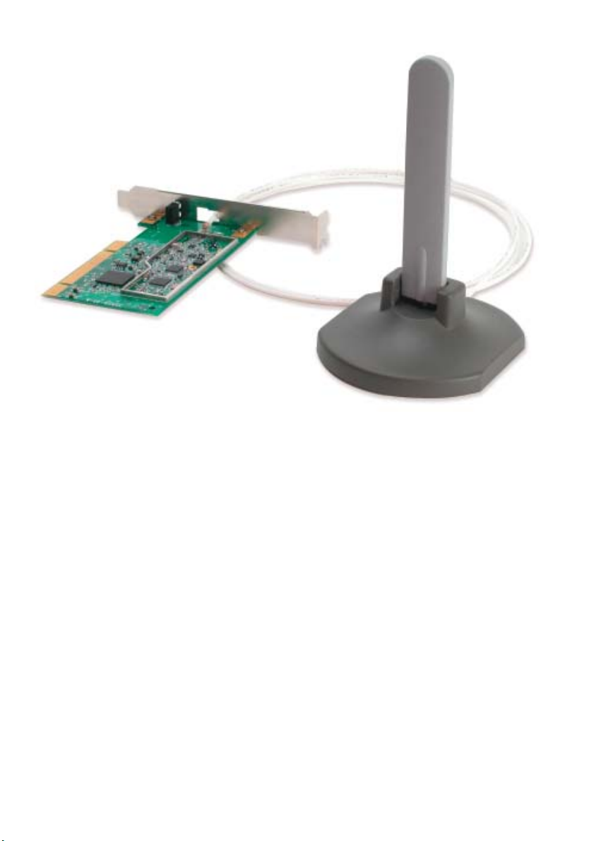
Package Contents
Contents of Package:
D-Link AirPro DWL-AB520
2.4 GHz / 5GHz Multimode Wireless PCI Adapter
Manual and Warranty on CD
Quick Installation Guide
If any of the above items are missing, please contact your reseller.
System Requirements:
A computer with an available 32-bit PCI slot
Windows XP, Windows 2000, Windows Me, or Windows 98SE
At least 32 MB of memory and a 300 MHz processor
An 802.11a/802.11b Multimode Access Point (e.g., DWL-
6000AP or DI-764), or an 802.11a Access Point (e.g., DWL-
5000AP for Infrastructure Mode), or an 802.11b Access
Point (e.g., DWL-900AP+), or an 802.11a wireless adapter
(e.g., DWL-A650 for laptops or DWL-A520 for Ad-Hoc
mode), or an 802.11b wireless adapter (e.g., DWL-650+.)
3
Page 4

Introduction
D-Link introduces the integrated multimode 802.11a/802.11b wireless PCI
Adapter, as part of the high performance D-Link AirPro series of wireless
networking products.
Featuring a breakthrough all-in-one multimode design, the new D-Link AirPro
DWL-AB520 Multimode Wireless PCI Adapter is a next generation PCI Adapter
that simultaneously serves both 802.11a wireless networks at 54 Mbps (72
*
Mbps in proprietary Turbo mode
The D-Link AirPro DWL-AB520 delivers the fastest IEEE standards-based
wireless technology in the industry and is interoperable with other 802.11a and
802.11b wireless devices.
After completing the steps outlined in the Quick Installation Guide (included in
your package) not only will you have the ability to share information and
resources, but you will also be able to enjoy the freedom that wireless networking
delivers, at speeds capable of handling large data files or video streams.
) and 802.11b wireless networks at 11Mbps.
*When used with other D-Link AirPro products.
4
Page 5

Features
Fully compatible with the 802.11a standard to provide an optimal wireless
54Mbps data rate (provides a 72Mbps data rate in proprietary Turbo Mode).
Fully compatible with the 802.11b standard to provide an optimal wireless
data rate of 11Mbps.
Dynamic data rate scaling at 6, 9, 12, 18, 24, 36, 48, 54 for 802.11a
Dynamic data rate scaling at 1, 2, 5.5, and 11Mbps for 802.11b
Maximum reliability, throughput and connectivity with automatic data rate
switching
Supports wireless data encryption with 64-bit WEP, 128-bit WEP and 152-bit
WEP with Dynamic Keying for more secure networking.
Provides an extended omni-directional antenna with 2 ~ 4dBi
Supports PCI Local Bus 2.2 standard
User-friendly configuration and diagnostic utilities
5
Page 6

LEDS
LED stands for Light-Emitting Diode. The DWL-AB520 has the following
LEDs as shown below:
LED
Power
Activity
A steady light indicates a connection to a power source
A blinking light indicates network activity
LED Activity
Wireless Basics
D-Link wireless products are based on industry standards to provide easyto-use and compatible high-speed wireless connectivity within your home,
business or public access wireless networks. Strictly adhering to the IEEE
standard, the D-Link wireless family of products will allow you to securely
access the data you want, when and where you want it. You will be able to
enjoy the freedom that wireless networking delivers.
A wireless local area network (WLAN) is a cellular computer network that
transmits and receives data with radio signals instead of wires. Wireless
LANs are used increasingly in both home and office environments, and
public areas such as airports, coffee shops and universities. Innovative ways
to utilize WLAN technology are helping people to work and communicate
more efficiently. Increased mobility and the absence of cabling and other
fixed infrastructure have proven to be beneficial for many users.
Wireless users can use the same applications they use on a wired network.
Wireless adapter cards used on laptop and desktop systems support the
same protocols as Ethernet adapter cards.
Under many circumstances, it may be desirable for mobile network devices
to link to a conventional Ethernet LAN in order to use servers, printers or an
Internet connection supplied through the wired LAN. A Wireless Router is a
device used to provide this link.
6
Page 7

Wireless Basics (continued)
People use wireless LAN technology for many different purposes:
Mobility - Productivity increases when people have access to data in any
location within the operating range of the WLAN. Management decisions based
on real-time information can significantly improve worker efficiency.
Low Implementation Costs – WLANs (Wireless Local Area Networks) are
easy to set up, manage, change and relocate. Networks that frequently change,
both physically and logically, can benefit from WLANs ease of implementation.
WLANs can operate in locations where installation of wiring may be impractical.
Installation Speed and Simplicity - Installing a wireless LAN system can
be fast and easy and can eliminate the need to pull cable through walls and
ceilings.
Network Expansion - Wireless technology allows the network to go
where wires cannot.
Scalability – Wireless Local Area Networks (WLANs) can be configured in a
variety of topologies to meet the needs of specific applications or existing
infrastructures. Configurations are easily changed and range from peer-topeer networks suitable for a small number of users to larger infrastructure
networks to accommodate hundreds or thousands of users, depending on the
number of wireless devices deployed.
7
Page 8

Wireless Basics (continued)
The DWL-AB520 is compatible with other D-Link AirPro 802.11a products,
which include:
♦ 5GHz Wireless Cardbus Adapters used with laptop computers
(DWL-A650)
♦ 5GHz Multimode Wireless Broadband Routers computers (DI-764,
and DI-754)
♦ 5GHz Wireless Access Points (DWL-5000AP, DWL-6000AP)
The DWL-AB520 is also compatible with D-Link Air and AirPlus 802.11b
wireless products, which include:
♦ 2.4GHz Wireless Cardbus Adapters used with laptop computers
(DWL-650, DWL-650+)
♦ 2.4GHz Wireless PCI cards used with desktop computers
(DWL-520, DWL-520+)
♦ Enhanced 2.4GHz Wireless Access Point (DWL-900AP+)
♦ Enhanced 2.4GHz Wireless Broadband Router (DI-614+)
Standards-Based Technology
The versatile DWL-AB520 Wireless Multimode PCI Adapter integrates both
802.11a and 802.11b standards into a single unit.
The IEEE 802.11a standard designates that devices may operate at an optimal
data rate of 54 Mbps (72 Mbps in proprietary Turbo mode.) This means that in
most environments, within the specified range of this device, you will be able to
transfer large files quickly or even watch a movie in MPEG format over your
network without noticeable delays. This technology works by transmitting highspeed digital data over a radio wave utilizing OFDM (Orthogonal Frequency
Division Multiplexing) technology. OFDM works by splitting the radio signal
into multiple smaller sub-signals that are then transmitted simultaneously at
different frequencies to the receiver. OFDM reduces the amount of crosstalk
(interference) in signal transmissions. D-Link AirPro 802.11a products will
automatically sense the best possible connection speed to ensure the greatest
speed and range possible.
Based on the IEEE 802.11b standard, the DWL-AB520 is also interoperable
with existing compatible 2.4GHz wireless technology with data transfer speeds
of up to 11Mbps.
8
Page 9

Wireless Basics (continued)
Installation Considerations
The D-Link AirPro DWL-AB520 lets you access your network, using a wireless
connection, from virtually anywhere. Keep in mind, however, that the number,
thickness and location of walls, ceilings, or other objects that the wireless signals
must pass through, may limit the range. Typical ranges vary depending on the
types of materials and background RF (radio frequency) noise in your home or
business. The key to maximizing wireless range is to follow these basic
guidelines:
1.
Keep the number of walls and ceilings between the DWL-AB520 and
other network devices to a minimum - each wall or ceiling can reduce
your D-Link AirPro Wireless product’s range from 3-90 feet (1-30 meters.)
Position your receiving devices so that the number of walls or ceilings is
minimized.
2. Be aware of the direct line between network devices. A wall that is
1.5 feet thick (.5 meters), at a 45-degree angle appears to be almost 3
feet (1 meter) thick. At a 2-degree angle it looks over 42 feet (14 meters)
thick! Try to make sure that devices are positioned so that the signal will
travel straight through a wall or ceiling for better reception.
3. Building Materials make a difference - a solid metal door or aluminum
studs may have a negative effect on range. Try to position wireless
devices and computers with wireless adapters so that the signal passes
through drywall or open doorways and not other materials.
4. Keep your product away (at least 3-6 feet or 1-2 meters) from electrical
devices or appliances that generate RF noise.
9
Page 10

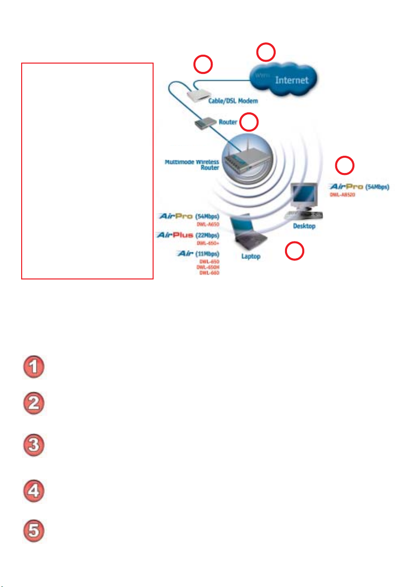
Getting Started
With its default settings, the DWL-AB520 will connect with
other D-Link AirPro products, right out of the box.
There are basically two modes of networking:
Infrastructure – using an Access Point, such as the DWL-900AP+,
DWL-5000AP or DWL-6000AP.
Ad-Hoc – directly connecting to another computer, for peer-to-peer
communication, using wireless network adapters on each computer, such
as two or more DWL-AB520 wireless network PCI adapters.
On the following pages we will show you an example of an Infrastructure
Network and an Ad-Hoc Network.
An Infrastructure network contains an Access Point or Router. The
Infrastructure Network example shown on the following page contains the
following D-Link network devices (your existing network may be comprised
of other devices):
A wireless Router - D-Link AirPro DI-764
A laptop computer with a wireless adapter -
D-Link AirPro DWL-A650 or AirPlus DWL-650+
A desktop computer with a wireless adapter -
D-Link AirPro DWL-AB520
A Cable modem - D-Link DCM-200
10
Page 11
Getting Started
Setting up a Wireless Infrastructure Network
Please refer to the following
sections of this manual for
additional information about
setting up a network:
2
1
Networking Basics - learn
how to check and assign
your IP Address; share
printers and files.
DI-764
3
4
Using the Configuration
Menu - learn the settings for
the DWL-AB520, using the
web-based interface.
Troubleshooting - learn
how to check for common
installation issues and other
tips for troubleshooting.
Please remember that D-Link AirPro wireless devices are pre-configured to connect
together, right out of the box, with their default settings.
For a typical wireless setup at home (as shown above), please do the
following:
You will need broadband Internet access (a Cable or DSL-subscriber line into
your home or office)
Consult with your Cable or DSL provider for proper installation of the modem
5
Connect the Cable or DSL modem to your broadband router (see the Quick
Installation Guide included with your router.)
Install the D-Link AirPro DWL-AB520 wireless PCI adapter into an available
PCI slot on your desktop computer. (See the Quick Installation Guide included
with the DWL-AB520.)
If you are connecting a laptop computer to your network, install the drivers for
the wireless cardbus adapter (e.g., D-Link AirPro DWL-A650, DWL-650+ or
the DWL-650) into a laptop computer. (See the Quick Installation Guide
included with the DWL-A650, DWL-650+, or DWL-650.)
11
Page 12
Getting Started
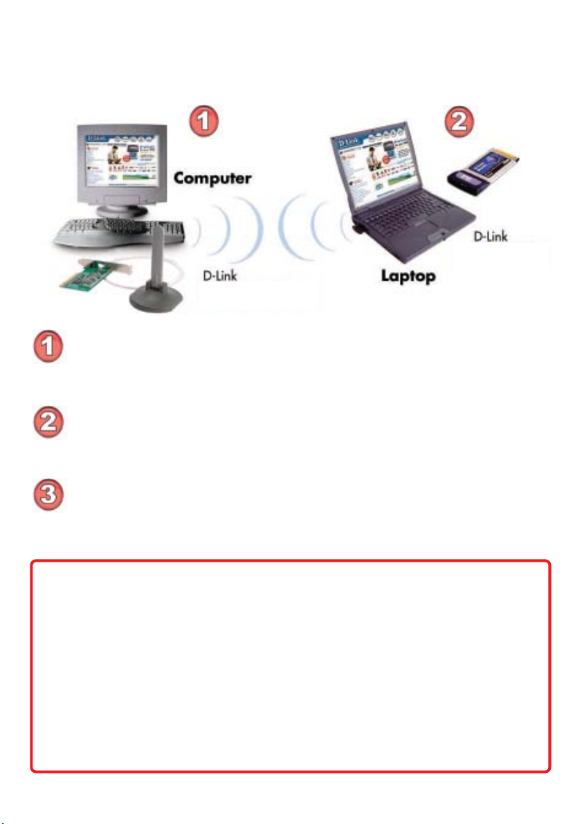
Setting up a Wireless Ad Hoc Network
DWL-AB520
Install the D-Link AirPro DWL-AB520 Wireless Network adapter
into the desktop computer.
with the product for installation instructions.
Install a wireless network adapter into the laptop computer. In the
example above the DWL-A650, DWL-650+ or DWL-650 may be
installed into a laptop computer.
included with the product.
See the Quick Installation Guide included
DWL-A650
DWL-650+
DWL-650
See the Quick Installation Guide
Set the wireless configuration for the adapters to Ad-Hoc mode, set
the adapters to the same channel, and assign an IP Address to
each computer on the Ad-Hoc network.
(See Box below)
IP Address
When assigning IP Addresses to the computers on the network, please
remember that the IP Address for each computer must be in the same
IP Address range as all the computers in the network, and the subnet
mask must be exactly the same for all the computers in the network.
For example: If the first computer is assigned an IP Address of 192.168.0.2
with a Subnet Mask of 255.255.255.0, then the second computer can be
assigned an IP Address of 192.168.0.3 with a Subnet Mask of 255.255.255.0,
etc.
IMPORTANT: If computers or other devices are assigned the same IP
Address, one or more of the devices may not be visible on the network.
12
Page 13

Using the Configuration Utility
If you want to alter the default settings or optimize the performance of the DWL-AB520,
D-Link has included a configuration utility to do so.
Note: With its default settings, the DWL-AB520 will associate with D-Link Air/
AirPro products such as the DI-764 (a wireless router), and the DWL-A650 (a
wireless adapter for laptops), right out of the box.
Before you use the configuration utility for the DWL-AB520, you must install the drivers
and the configuration utility by inserting the CD-ROM that came with the DWL-AB520.
(Please see the Quick Installation Guide that came with the product.) After you have
completed this installation and restarted your computer, you can access the Configuration Utility at any time by clicking on the icon in your taskbar at the bottom right corner
of your PC’s screen.
After double-clicking on the icon in the taskbar (shown at right), the
following Configuration Utility window will appear:
Configuration
13
Page 14

Using the Configuration Utility
Configuration (continued)
Refresh-
Add-
New-
Remove-
Move up-
Move down-
Properties-
click Refresh to display the current networks available
highlight the network to which you wish to connect and click
Add
click New to connect to the Preferred WLAN
click Remove to eliminate the highlighted network
click Move up to move the network up higher in the list
click Move down to move the network lower in the list
click Properties to configure the highlighted network and the
screen below will appear
Configuration>Properties
14
Page 15

Using the Configuration Utility
Configuration>Advanced
Click on Advanced in the Configuration window to select the type of WLAN (Wireless Local Area Network) to which you wish to connect. Select from the following
options in the Advanced pop-up window:
WLAN type to connect
Infrastructure
and ad-hoc
choose this option to connect to both Infrastructure and AdHoc networks
network-
Infrastructure
network only-
Ad-hoc
network only-
Automatically
connect to
choose this option to connect to Infrastructure networks only
(networks with an Access Point like the DI-764)
choose this option to connect directly to another ethernet adapter
equipped computer
choose this option to connect to any available network.
(This option could result in a security risk.)
non-preferred
networks-
Close-
click Close to save the changes.
15
Page 16

Using the Configuration Utility
Status
If you enable WEP encryption or Turbo Mode make sure to enable WEP
encryption and Turbo Mode on all the devices in your network.
The Status screen displays the current properties of the DWL-AB520.
Connection Status-
Network Name-
Network Type-
WEP Status-
WEP stands for Wired Equivalent Privacy. It is a
security protocol for Wireless Local Area Networks
indicates the connection status: either connected or disconnected.
displays the network name that you have input
indicates either Infrastructure, Ad-Hoc or Infrastructure and
Ad-Hoc
either Enable or Disable
Speed- indicates data rate speed
Signal Strength-
MAC Address-
Radio Status-
Turbo Mode-
Click OK or Apply-
displays the signal strength
Media Access Control address is a unique hardware address
that identifies the DWL-AB520 on the network
ON or OFF
Enable or Disable. Disable is the default setting
click Apply to save the changes
16
Page 17

Using the Configuration Utility
Option
General Setting
Click on the
About tab
to find out
the firmware
version
Auto Launch
when Windows
starts up-
Advance Setting
Enable Turbo
Mode-
Encryption Type-
Power Save Mode-
Radio Frequency-
Click OK or Apply-
automatically enables the adapter when Windows starts up. By
defaut this option is selected.
disable is the default setting. Make sure all devices in your network have identical settings for Turbo mode
select from Auto, WEP or AES
select from Fast Save, Max. Save or Disable. Default is Fast
Save.
select from 802.11b - 2.4GHz, 802.11a - 5GHz or Auto.
Default is Auto.
click Apply to save the changes; click OK to close the utility
17
Page 18

Networking Basics
Using the Network Setup Wizard in Windows XP
In this section you will learn how to establish a network at home or work,
using Microsoft Windows XP.
Note: Please refer to websites such as
and http://www.microsoft.com/windows2000 for information about
networking computers using Windows 2000, ME or 98SE.
Go to Start>Control Panel>Network Connections
Select Set up a home or small office network
http://www.homenethelp.com
When this screen appears, Click Next.
18
Page 19

Networking Basics
Please follow all the instructions in this window:
Click Next
In the following window, select the best description of your computer. If your
computer connects to the internet through a gateway/router, select the
second option as shown.
Click Next
19
Page 20

Networking Basics
Enter a Computer description and a Computer name (optional.)
Click Next
Enter a Workgroup name. All computers on your network should have the
same Workgroup name.
Click Next
20
Page 21

Networking Basics
Please wait while the Network Setup Wizard applies the changes.
When the changes are complete, click Next.
Please wait while the Network Setup Wizard configures the computer.
This may take a few minutes.
21
Page 22

Networking Basics
In the window below, select the option that fits your needs. In this example, Create
a Network Setup Disk has been selected. You will run this disk on each of the
computers on your network. Click Next.
Insert a disk into the Floppy Disk Drive, in this case drive A.
22
Page 23

Networking Basics
Please read the information under Here’s how in the screen below. After you complete the Network Setup Wizard you will use the Network Setup Disk to run the
Network Setup Wizard once on each of the computers on your network. To continue
click Next.
23
Page 24

Networking Basics
Please read the information on this screen, then click Finish to complete the
Network Setup Wizard.
The new settings will take effect when you restart the computer. Click Yes to
restart the computer.
You have completed configuring this computer. Next, you will need to run the
Network Setup Disk on all the other computers on your network. After running the Network Setup Disk on all your computers, your new wireless network will be ready to use.
24
Page 25

Networking Basics
Naming your Computer
To name your computer, please follow these directions:In Windows XP:
Click Start (in the lower left corner of the screen)
Right-click on My Computer
Select Properties and click
Select the Computer
Name Tab in the System
Properties window.
You may enter a Computer Description if you
wish; this field is optional.
To rename the computer
and join a domain, Click
Change.
25
Page 26

Networking Basics
Naming your Computer
In this window, enter the
Computer name
Select Workgroup and enter
the name of the Workgroup
All computers on your network
must have the same
Workgroup name.
Click OK
Checking the IP Address in Windows XP
The wireless adapter-equipped computers in your network must be in the same IP
Address range (see Getting Started in this manual for a definition of IP Address Range.)
To check on the IP Address of the adapter, please do the following:
Right-click on the
Local Area
Connection icon
in the task bar
Click on Status
26
Page 27

Networking Basics
Checking the IP Address in Windows XP
This window will appear.
Click the
Support tab
Click Close
Assigning a Static IP Address in Windows XP/2000
Note: Residential Gateways/Broadband Routers will automatically assign IP Addresses to the computers on the network, using DHCP (Dynamic Host Configuration Protocol) technology. If you are using a DHCP-capable Gateway/Router you
will not need to assign Static IP Addresses.
If you are not using a DHCP capable Gateway/Router, or you need to assign a Static IP
Address, please follow these instructions:
Go to Start
Double-click on
Control Panel
27
Page 28

Networking Basics
Assigning a Static IP Address in Windows XP/2000
Double-click on
Network
Connections
Right-click on Local Area
Connections
Double-click on
Properties
28
Page 29

Networking Basics
Assigning a Static IP Address
in Windows XP/2000
Click on Internet Protocol
(TCP/IP)
Click Properties
Input your IP address and
subnet mask. (The IP
Addresses on your network
must be within the same
range. For example, if one
computer has an IP Address
of 192.168.0.2, the other
computers should have IP
Addresses that are
sequential, like 192.168.0.3
and 192.168.0.4. The
subnet mask must be the
same for all the computers
on the network.)
Input your DNS server
addresses. (Note: If you
are entering a DNS server,
you must enter the IP
Address of the Default
Gateway.)
The DNS server information will be supplied
by your ISP (Internet Service Provider.)
Click OK
29
Page 30

Networking Basics
Checking the Wireless Connection by Pinging in Windows XP and
2000
Go to Start > Run >
type cmd. A window
similar to this one
will appear. Type
ping
xxx.xxx.xxx.xxx,
where xxx is the IP
Address of the
Wireless Router or
Access Point. A
good wireless
connection will show
four replies from the
Wireless Router or
Acess Point, as
shown.
Checking the Wireless Connection by Pinging in Windows Me
and 98
Go to Start > Run
> type command.
A window similar to
this will appear.
Type ping
xxx.xxx.xxx.xxx
where xxx is the IP
Address of the
Wireless Router or
Access Point. A
good wireless
connection will
show four replies
from the wireless
router or access
point, as shown.
30
Page 31

Troubleshooting
This chapter provides solutions to problems that can occur during the installation and
operation of the DWL-AB520. Read the following descriptions if you are having problems. (The examples below are illustrated in Windows XP. If you have another operating system, these solutions will still apply although the appearance on your computer
screen may differ.)
1. Check that the drivers for the DWL-AB520 are installed properly.
Go to Start >
My Computer >
Properties
Select the
Hardware
Tab
Click Device
Manager
31
Page 32

Troubleshooting
Double-click
on Network
Adapters
Right-click on D-Link
AirPro DWL-AB520
Wireless PCI Adapter
Select Properties
to check that the
drivers are
installed properly
Look under Device
Status to check that the
device is working
properly
Click OK
D-Link AirPro DWL-AB520 Wireless PCI Adapter
D-Link AirPro DWL-AB520 Wireless PCI Adapter
32
Page 33

Troubleshooting
2. What variables may cause my wireless products to lose reception?
D-Link products let you access your network from virtually anywhere you want.
However, the positioning of the products within your environment will affect the
wireless range. Please refer to Installation Considerations in the Wireless
Basics section of this manual for further information about the most advantageous placement of your D-Link wireless products.
3. Why does my wireless connection keep dropping?
Antenna Orientation- Try different antenna orientations for the DWL-
AB520. Try to keep the antenna at least 6 inches away from the wall
or other objects.
If you are using 2.4GHz cordless phones, X-10 equipment or other home
security systems, ceiling fans, and lights, your wireless connection will
degrade dramatically or drop altogether. Try changing the Channel on
your Router, Access Point and Wireless adapter to a different Channel
to avoid interference.
Keep your product away (at least 3-6 feet) from electrical devices that
generate RF noise, like microwaves, Monitors, electric motors, etc.
4. Why can’t I get a wireless connection?
If you have enabled Encryption on the DWL-AB520, you must also enable encryption on all wireless devices in the network in order to establish a wireless
connection.
For 802.11a, the Encryption settings are: 64, 128 or 152 bit. Make sure
that the encryption bit level is the same on the Router (if you have an
infrastructure network) and the DWL-AB520.
For 802.11b, the Encryption settings are: 64, 128, or 256 bit. Make sure
that the encryption bit level is the same on the Router and the DWLAB520.
Make sure that the SSID on the Router (if you have one in your network)
and the DWL-AB520 are exactly the same. If they are not, wireless
connection will not be established. Please note that there are two separate SSIDs for 802.11a and 802.11b. The default SSID for both 802.11a
and 802.11b is default.
33
Page 34

Technical Specifications
Standards
IEEE 802.11b
IEEE 802.11a
Diagnostic LED
Power
Network
Temperature
Operating: 0ºC to 55ºC (32ºF to 131ºF)
Storing: -20ºC to 75ºC (-4ºF to 167ºF)
Humidity:
10%-90%, non-condensing
Antenna Type:
Omni-directional dipole antenna with 2~4dB
Operating Voltage:
3.3VDC +/-10%
MTBF:
Mean time between failure >30,000 hours
Emissions:
FCC part 15b
Physical Dimensions:
L = 6.6 inches
W = 4.2 inches
H = 1.6 inches
34
Page 35

Technical Specifications
802.11a Specifications
Standard:
IEEE 802.11a
Data Rates:
6, 9, 12, 18, 24, 36, 48, 54 (72 Mbps in Turbo mode)
Encryption:
Supports 64-bit, 128-bit, and 152-bit WEP encryption
with Dynamic keying
Available Channels:
12 non-overlapping channels for North America
Frequency Range:
5.150 – 5.350 and 5.725 ~ 5.825 GHz
Modulation Technology:
Orthogonal Frequency Division Multiplexing (OFDM)
Media Access Protocol:
CSMA/CA with ACK
Modulation Techniques:
BPSK
QPSK
16 QAM
64 QAM
802.11b Specifications
Standard:
IEEE 802.11b
Data Rates:
1, 2, 5.5, 11Mbps (with Automatic Fallback)
Available Channels:
Eleven channels for North America. Three non-overlapping.
Transmitter Output Power:
+13 ~ 14dBm at 54Mbps
Receiver Sensitivity:
-66dBm at 54Mbps
35
Page 36

Technical Specifications
802.11b Specifications
Encryption:
Supports 64-bit or 128-bit WEP encryption
Frequency Range:
2.4 – 2.497 GHz
Modulation Techniques:
DQPSK
DBPSK
DSSS
CCK
Media Access Protocol:
CSMA/CA with ACK
Transmitter Output Power:
+18dBm at 11,5.5,2 and 1 Mbps
Receiver Sensitivity:
-84dBm for 11Mbps @ 8% PER
Contacting Technical Support
You can find the most recent software and user documentation on the D-Link
website.
D-Link provides free technical support for customers within the United States
for the duration of the warranty period on this product.
U.S. customers can contact D-Link technical support through our web site,
or by phone.
D-Link Technical Support over the Telephone:
(877) 453-5465
24 hours a day, seven days a week.
D-Link Technical Support over the Internet:
http://support.dlink.com
When contacting technical support, please provide the following information:
Serial number of the unit
Model number or product name
Software type and version number
36
Page 37

Warranty and Registration
Subject to the terms and conditions set forth herein, D-Link Systems, Inc. (“D-Link”) provides this Limited
warranty for its product only to the person or entity that originally purchased the product from:
D-Link or its authorized reseller or distributor and
Products purchased and delivered within the fifty states of the United States, the District of
Columbia, U.S. Possessions or Protectorates, U.S. Military Installations, addresses with an
APO or FPO.
Limited Warranty: D-Link warrants that the hardware portion of the D-Link products described below will
be free from material defects in workmanship and materials from the date of original retail purchase of the
product, for the period set forth below applicable to the product type (“Warranty Period”), except as
otherwise stated herein.
3-Year Limited Warranty for the Product(s) is defined as follows:
Hardware (excluding power supplies and fans) Three (3) Years
Power Supplies and Fans One (1) Year
Spare parts and spare kits Ninety (90) days
D-Link’s sole obligation shall be to repair or replace the defective Hardware during the Warranty Period at
no charge to the original owner or to refund at D-Link’s sole discretion. Such repair or replacement will be
rendered by D-Link at an Authorized D-Link Service Office. The replacement Hardware need not be new
or have an identical make, model or part. D-Link may in its sole discretion replace the defective Hardware
(or any part thereof) with any reconditioned product that D-Link reasonably determines is substantially
equivalent (or superior) in all material respects to the defective Hardware. Repaired or replacement
Hardware will be warranted for the remainder of the original Warranty Period from the date of original
retail purchase. If a material defect is incapable of correction, or if D-Link determines in its sole discretion
that it is not practical to repair or replace the defective Hardware, the price paid by the original purchaser
for the defective Hardware will be refunded by D-Link upon return to D-Link of the defective Hardware. All
Hardware (or part thereof) that is replaced by D-Link, or for which the purchase price is refunded, shall
become the property of D-Link upon replacement or refund.
Limited Software Warranty: D-Link warrants that the software portion of the product (“Software”) will
substantially conform to D-Link’s then current functional specifications for the Software, as set forth in the
applicable documentation, from the date of original retail purchase of the Software for a period of ninety
(90) days (“Warranty Period”), provided that the Software is properly installed on approved hardware and
operated as contemplated in its documentation. D-Link further warrants that, during the Warranty Period,
the magnetic media on which D-Link delivers the Software will be free of physical defects. D-Link’s sole
obligation shall be to replace the non-conforming Software (or defective media) with software that
substantially conforms to D-Link’s functional specifications for the Software or to refund at D-Link’s sole
discretion. Except as otherwise agreed by D-Link in writing, the replacement Software is provided only to
the original licensee, and is subject to the terms and conditions of the license granted by D-Link for the
Software. Software will be warranted for the remainder of the original Warranty Period from the date or
original retail purchase. If a material non-conformance is incapable of correction, or if D-Link determines
in its sole discretion that it is not practical to replace the non-conforming Software, the price paid by the
original licensee for the non-conforming Software will be refunded by D-Link; provided that the nonconforming Software (and all copies thereof) is first returned to D-Link. The license granted respecting
any Software for which a refund is given automatically terminates.
Non-Applicability of Warranty: The Limited Warranty provided hereunder for hardware and software of
D-Link’s products, will not be applied to and does not cover any product purchased through the inventory
clearance or liquidation sale or other sales in which D-Link, the sellers, or the liquidators expressly disclaim
their warranty obligation pertaining to the product and in that case, the product is being sold “As-Is”
without any warranty whatsoever including, without limitation, the Limited Warranty as described herein,
notwithstanding anything stated herein to the contrary.
Submitting A Claim: Any claim under this limited warranty must be submitted in writing before the end
of the Warranty Period to an Authorized D-Link Service Office.
The customer must submit as part of the claim (a written description of the Hardware defect or
Software nonconformance) in sufficient detail to allow D-Link to confirm the same.
The original product owner must obtain a Return Material Authorization (“RMA”) number from
the Authorized D-Link Service Office and, if requested, provide written proof of purchase of the
product (such as a copy of the dated purchase invoice for the product) before the warranty
service is provided.
37
Page 38

After an RMA number is issued, the defective product must be packaged securely in the original
or other suitable shipping package to ensure that it will not be damaged in transit, and the RMA
number must be prominently marked on the outside of the package. Do not include any manuals
or accessories in the shipping package. D-Link will only replace the defective portion of the
Product and will not ship back any accessories.
The customer is responsible for all shipping charges to D-Link. No Charge on Delivery (“COD”)
is allowed. Products sent COD will either be rejected by D-Link or become the property of DLink. Products should be fully insured by the customer and shipped to D-Link Systems, Inc.,
53 Discovery Drive, Irvine, CA 92618. D-Link will not be held responsible for any packages
that are lost in transit to D-Link. The repaired or replaced packages will be shipped via UPS
Ground or any common carrier selected by D-Link, with shipping charges prepaid. Expedited
shipping is available if shipping charges are prepaid by the customer.
D-Link may reject or return any product that is not packaged and shipped in strict compliance with the
foregoing requirements, or for which an RMA number is not visible from the outside of the package. The
product owner agrees to pay D-Link’s reasonable handling and return shipping charges for any product
that is not packaged and shipped in accordance with the foregoing requirements, or that is determined by
D-Link not to be defective or non-conforming.
What Is Not Covered: This limited warranty provided by D-Link does not cover: Products, if in D-Link’s
judgment, have been subjected to abuse, accident, alteration, modification, tampering, negligence, misuse,
faulty installation, lack of reasonable care, repair or service in any way that is not contemplated in the
documentation for the product, or if the model or serial number has been altered, tampered with, defaced
or removed; Initial installation, installation and removal of the product for repair, and shipping costs;
Operational adjustments covered in the operating manual for the product, and normal maintenance; Damage
that occurs in shipment, due to act of God, failures due to power surge, and cosmetic damage; Any
hardware, software, firmware or other products or services provided by anyone other than D-Link; Products
that have been purchased from inventory clearance or liquidation sales or other sales in which D-Link, the
sellers, or the liquidators expressly disclaim their warranty obligation pertaining to the product. Repair by
anyone other than D-Link or an Authorized D-Link Service Office will void this Warranty.
Disclaimer of Other Warranties: EXCEPT FOR THE LIMITED WARRANTY SPECIFIED HEREIN, THE PRODUCT IS PROVIDED
“AS-IS” WITHOUT ANY WARRANTY OF ANY KIND WHATSOEVER INCLUDING, WITHOUT LIMITATION, ANY WARRANTY OF
MERCHANTABILITY, FITNESS FOR A PARTICULAR PURPOSE AND NON-INFRINGEMENT. IF ANY IMPLIED WARRANTY CANNOT BE
DISCLAIMED IN ANY TERRITORY WHERE A PRODUCT IS SOLD, THE DURATION OF SUCH IMPLIED WARRANTY SHALL BE LIMITED
TO NINETY (90) DAYS. EXCEPT AS EXPRESSLY COVERED UNDER THE LIMITED WARRANTY PROVIDED HEREIN, THE ENTIRE
RISK AS TO THE QUALITY, SELECTION AND PERFORMANCE OF THE PRODUCT IS WITH THE PURCHASER OF THE PRODUCT.
Limitation of Liability: TO THE MAXIMUM EXTENT PERMITTED BY LAW, D-LINK IS NOT LIABLE UNDER ANY CONTRACT,
NEGLIGENCE, STRICT LIABILITY OR OTHER LEGAL OR EQUITABLE THEORY FOR ANY LOSS OF USE OF THE PRODUCT,
INCONVENIENCE OR DAMAGES OF ANY CHARACTER, WHETHER DIRECT, SPECIAL, INCIDENTAL OR CONSEQUENTIAL (INCLUDING,
BUT NOT LIMITED TO, DAMAGES FOR LOSS OF GOODWILL, LOSS OF REVENUE OR PROFIT, WORK STOPPAGE, COMPUTER
FAILURE OR MALFUNCTION, FAILURE OF OTHER EQUIPMENT OR COMPUTER PROGRAMS TO WHICH D-LINK’S PRODUCT IS
CONNECTED WITH, LOSS OF INFORMATION OR DATA CONTAINED IN, STORED ON, OR INTEGRATED WITH ANY PRODUCT
RETURNED TO D-LINK FOR WARRANTY SERVICE) RESULTING FROM THE USE OF THE PRODUCT, RELATING TO WARRANTY
SERVICE, OR ARISING OUT OF ANY BREACH OF THIS LIMITED WARRANTY, EVEN IF D-LINK HAS BEEN ADVISED OF THE
POSSIBILITY OF SUCH DAMAGES. THE SOLE REMEDY FOR A BREACH OF THE FOREGOING LIMITED WARRANTY IS REPAIR,
REPLACEMENT OR REFUND OF THE DEFECTIVE OR NON-CONFORMING PRODUCT. THE MAXIMUM LIABILITY OF D-LINK UNDER
THIS WARRANTY IS LIMITED TO THE PURCHASE PRICE OF THE PRODUCT COVERED BY THE WARRANTY. THE FOREGOING
EXPRESS WRITTEN WARRANTIES AND REMEDIES ARE EXCLUSIVE AND ARE IN LIEU OF ANY OTHER WARRANTIES OR REMEDIES,
EXPRESS, IMPLIED OR STATUTORY
Governing Law: This Limited Warranty shall be governed by the laws of the State of California. Some
states do not allow exclusion or limitation of incidental or consequential damages, or limitations on how
long an implied warranty lasts, so the foregoing limitations and exclusions may not apply. This limited
warranty provides specific legal rights and the product owner may also have other rights which vary from
state to state.
Trademarks: D-Link is a registered trademark of D-Link Systems, Inc. Other trademarks or registered
trademarks are the property of their respective manufacturers or owners.
Copyright Statement: No part of this publication or documentation accompanying this Product may
be reproduced in any form or by any means or used to make any derivative such as translation,
transformation, or adaptation without permission from D-Link Corporation/D-Link Systems, Inc., as
stipulated by the United States Copyright Act of 1976. Contents are subject to change without prior
notice. Copyright© 2002 by D-Link Corporation/D-Link Systems, Inc. All rights reserved.
38
Page 39

FCC Statement: This equipment has been tested and found to comply with the limits for a Class B digital
device, pursuant to part 15 of the FCC Rules. These limits are designed to provide reasonable protection
against harmful interference in a residential installation. This equipment generates, uses, and can radiate
radio frequency energy and, if not installed and used in accordance with the instructions, may cause
harmful interference to radio communication. However, there is no guarantee that interference will not
occur in a particular installation. If this equipment does cause harmful interference to radio or television
reception, which can be determined by turning the equipment off and on, the user is encouraged to try to
correct the interference by one or more of the following measures:
Reorient or relocate the receiving antenna
Increase the separation between the equipment and the receiver
Connect the equipment into an outlet on a circuit different from that to which the
receiver is connected
Consult the dealer or an experienced radio/TV technician for help
Registration: Register your D-Link AirPro DWL-AB520 online at http://support.dlink.com/register
(09/25/2002)
39
 Loading...