

D-Link DSN-5410-10, DSN-5000-10, DSN-5110-10, DSN-5210-10 Software Manual
D-Link xStack Storage iSCSI SAN Arrays
Managed SAN Solutions
DSN-5000 Series
(DSN-5110-10, 5210-10, 5410-10, 5000-10)
Management Center Software User’s Guide
Version 1.3

© 2010 D-Link Systems, Inc. All Rights Reserved
D-Link Systems, Inc. makes no warranty of any kind with regard to this material, including,
but not limited to, the implied warranties of merchantability and fitness for a particular
purpose. D-Link Systems, Inc. shall not be liable for errors contained herein or for incidental
or consequential damages in connection with the furnishing, performance, or use of this
material.
This document contains proprietary information, which is protected by copyright. No part of
this document may be photocopied, reproduced, or translated into another language without
the prior written consent of D-Link Systems, Inc.
The information is provided “as is” without warranty of any kind and is subject to change
without notice. The only warranties for D-Link products and services are set forth in the
express warranty statements accompanying such products and services. Nothing herein
should be construed as constituting an additional warranty. D-Link shall not be liable for
technical or editorial errors or omissions contained herein.
Copyright © 2010 D-Link Systems, Inc.™
Trademarks
Includes one or more of the following United States patents: 6,941,396; 7,353,306;
7,389,462; 7,460,473; 7,512,663 and 7,594,002. Other patents pending.
D-Link and the D-Link logo are registered trademarks of D-Link, Inc.
Java™ is a U.S. trademark of Sun Microsystems, Incorporated.
Microsoft Windows is a U.S. registered trademark of Microsoft Corporation..
All other brand or product names are or may be trademarks or service marks, and are used
to identify products or services, of their respective owners.
D-Link Systems, Inc.
17595 Mount Herrmann Street
Fountain Valley, CA 92708
ii Contents

Notice of Export Controls
Export of technical data contained in this document may require an export license from the
United States government. Please contact D-Link, Inc. for any export compliance questions.
Document Revision Level
Revision Date Description
1.0 July 2008 Version 1.0 – Initial release based on Software version 2.0.0
1.1 September 2008 Version 1.1 – Updated for software version 2.5.0 and redundant controller support
1.2 January 2009 Version 1.2 – Updated for software version 2.5.1 and minor formatting corrections
1.3 May 2010 Version 1.3 – Updated for software version 2.7.0 and added more summary
information to Chapter 1
xStack Storage Management Center Software User’s Guide iii

Preface
This document is intended to assist users with configuring and managing storage on xStack
Storage® systems from D-Link Systems .
Audience
This document is intended for storage managers and administrators responsible for using the
xStack Storage Management Center to configure and manage the xStack Storage array from
D-Link Systems Inc. This document assumes that the user is computer literate, familiar with
storage array products, and has a basic understanding of storage products and concepts.
Typographic Conventions
Notes
Notes provide information that deserves special attention. They are preceded by:
Cautions
Cautions contain information which, if not followed, can cause damage to the
xStack Storage array and possible loss of data. They are preceded by:
Warnings
Warnings contain information which, if not followed, can cause damage to the
xStack Storage array and to the person installing it. They are preceded by:
iv Contents

Contact Information
You can find software updates and user documentation on the D-Link website.
D-Link provides free technical support for customers within the United States and within
Canada for the duration of the warranty period on this product.
U.S. and Canadian customers can contact D-Link Technical Support through our website, or
by phone.
Tech Support for customers within the United States:
D-Link Technical Support over the Telephone
Please see our support site for current number:
http://support.dlink.com
Monday to Friday 8:00am – 5:00pm PST/PDT
D-Link Technical Support over the Internet:
http://support.dlink.com
Tech Support for customers within Canada:
D-Link Technical Support over the Telephone
Please see our support site for current number:
http://support.dlink.ca
Monday to Friday 7:30am to 9:00pm EST/EDT
D-Link Technical Support over the Internet:
http://support.dlink.ca
xStack Storage Management Center Software User’s Guide v

Contents
Chapter 1 Introduction......................................................................................................................................1
1.1 Product Overview ....................................................................................2
1.2 Terminology and Concepts..........................................................................2
1.3 Storage Pools and Drives............................................................................3
1.4 Volumes................................................................................................4
1.5 Tasks....................................................................................................6
1.5.1 Initialize a Parity Volume..................................................................6
1.5.2 Rebuild a Volume...........................................................................6
1.5.3 Scan a Volume...............................................................................7
1.5.4 Grow (Expand) a Volume..................................................................7
1.5.5 Reconfigure a Volume......................................................................7
1.6 Network Portals.......................................................................................7
1.7 VLANs...................................................................................................8
1.8 LAGs ....................................................................................................8
1.9 iSCSI Target Nodes ...................................................................................8
1.10 iSCSI Log-In, Sessions and Connections..........................................................8
1.11 Multiple Connections per Session ................................................................8
Chapter 2 Overview of the Management Center Software...........................................................................9
2.1 Key Features ..........................................................................................9
2.2 Compatibility and Minimum System Requirements........................................... 10
2.3 Understanding the Basics.........................................................................10
2.3.1 Understanding the User Interface......................................................11
2.3.2 Menu Bar and Toolbar....................................................................11
2.3.3 View Panel .................................................................................13
2.3.4 Main Display................................................................................ 14
2.3.5 Action Panels ..............................................................................14
2.3.6 Detail Tabs.................................................................................15
2.3.7 Status Bar ..................................................................................15
2.4 Getting Help.........................................................................................15
2.5 READ THIS SECTION - If You Read Nothing Else In This Guide..............................16
Chapter 3 Getting Started...............................................................................................................................17
3.1 Connecting and Logging In........................................................................ 18
3.1.1 Using the Start-up Wizard...............................................................18
3.1.2 Logging in from the Home Page........................................................24
3.2 Setting the System Date and Time.............................................................. 26
3.3 Customizing the Date and Time Display........................................................28
3.4 Configuring User Accounts........................................................................ 29
3.4.1 Changing the Default Admin Login Password ........................................29
3.4.2 Adding Admin Accounts..................................................................30
3.4.3 Adding User Accounts.................................................................... 31
3.4.4 Modifying Accounts....................................................................... 32
3.4.5 Deleting User Accounts..................................................................32
3.5 Logging Out..........................................................................................33
3.6 Exiting the xStack Storage Management Center..............................................33
3.7 Shutting Down the xStack Storage Array....................................................... 34
vi Contents

Chapter 4 Managing Volumes ........................................................................................................................35
4.1 Understanding the Volume View.................................................................36
4.2 Creating Volumes...................................................................................37
4.2.1 Letting the Wizard Choose the Best Volume Organization.........................39
4.2.2 Making Your Own Volume Selection Choices.........................................45
4.3 Performing Volume Actions.......................................................................51
4.3.1 Modifying iSCSI Initiator Access to Volumes..........................................51
4.3.2 Scanning a Volume........................................................................53
4.3.3 Destroying a Volume......................................................................54
4.3.4 Growing a Volume.........................................................................55
4.3.5 Reconfiguring a Volume..................................................................56
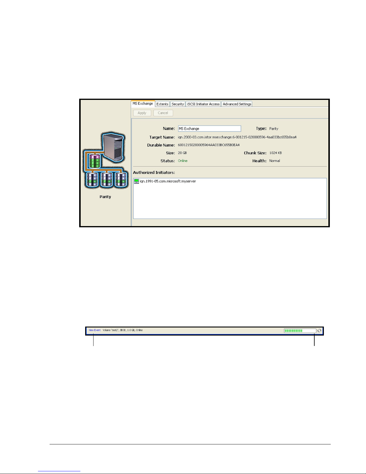
4.4 Using the Detail Tabs..............................................................................59
4.4.1 Changing Volume Names and Viewing Volume Information (Properties Tab) ..59
4.4.2 Viewing Extents on a Volume (Extents Tab)..........................................60
4.4.3 Viewing Reconfiguration Information (Reconfigure Tab) ..........................62
4.4.4 Enabling or Disabling CHAP Security for Volumes (Security Tab).................63
4.4.5 Viewing or Changing Advanced Settings (Advanced Settings Tab) ...............65
4.4.6 Enabling or Disabling CHAP Security for Initiators (Security Tab)................68
4.5 Removing iSCSI Initiators..........................................................................69
Chapter 5 Managing Physical Storage..........................................................................................................71
5.1 Understanding the Physical Storage View......................................................72
5.2 Performing Drive Actions..........................................................................73
5.2.1 Initializing a Drive.........................................................................73
5.2.2 Downing a Drive...........................................................................74
5.2.3 Reserving Spare Drives...................................................................75
5.3 Using the Detail Tabs..............................................................................76
5.3.1 Viewing Drive Properties (Properties Tab) ...........................................76
5.3.2 Viewing Extents on a Drive (Extents Tab) ............................................77
5.3.3 Viewing SMART Data and Attributes (SMART Data and SMART Attributes Tabs)78
Chapter 6 System Administration..................................................................................................................81
6.1 Understanding the System Administration View ..............................................82
6.1.1 Single-Controller Systems................................................................82
6.1.2 Dual-Controller Systems .................................................................83
6.2 Using the Detail Tabs..............................................................................85
6.2.1 Viewing System Summary Information (Summary Tab).............................85
6.2.2 Viewing Historical Information (History Tab) ........................................85
6.2.3 Controller Details (Controller Tab) ....................................................87
6.2.4 Viewing Scheduled Activities (Tasks Tab).............................................88
6.2.5 Saving the Current Configuration (Settings Tab)....................................89
6.2.6 Restoring a Configuration (Control Tab)..............................................91
6.2.7 Restoring Factory Default Settings.....................................................92
6.2.8 Upgrading Software (Control Tab) .....................................................92
6.2.9 Restarting the xStack Storage (Control Tab).........................................93
6.2.10 Shutting Down the xStack Storage (Control Tab)..................................93
6.2.11 Selecting a Battery Policy and System Failure Policy (System Policy Tab)....94
6.2.12 Configuring User Accounts (Settings Tab)...........................................95
6.2.13 Viewing or Changing Advanced Settings (Settings Tab)...........................96
Chapter 7 Managing Management and Ethernet Ports and Portals.......................................................103
7.1 Understanding the Network Settings View....................................................104
xStack Storage Management Center Software User’s Guide vii

7.2 Working with Management Ports ...............................................................105
7.2.1 Viewing or Changing Management Port Settings ...................................105
7.2.2 Pinging from a Management Port .....................................................106
7.3 Viewing or Changing the Ethernet Port Settings.............................................107
7.4 Working with Network Portals ..................................................................109
7.4.1 Creating Network Portals...............................................................109
7.4.2 Deleting a Network Portal..............................................................110
7.4.3 Pinging from a Network Portal ........................................................111
7.5 Grouping and Ungrouping Ports.................................................................112
7.5.1 Grouping Ports............................................................................113
7.5.2 Ungrouping Ports.........................................................................115
7.5.3 Removing Ports from a LAG............................................................115
7.6 Working with VLANs...............................................................................116
7.6.1 VLAN-Enabling a Port....................................................................117
7.6.2 Removing a Port from a VLAN .........................................................117
7.6.3 VLAN-Enabling a Group .................................................................117
7.6.4 Removing a Group from a VLAN.......................................................117
Chapter 8 Performing System Actions.......................................................................................................119
8.1 Adding an xStack Storage........................................................................119
8.2 Removing an xStack Storage.....................................................................120
8.3 Force System Failover............................................................................121
Chapter 9 Best Practices..............................................................................................................................123
9.1 Saving Configuration Settings ...................................................................124
9.2 Resetting Display Preferences...................................................................124
9.3 Working with Firewalls...........................................................................124
Chapter 10 Troubleshooting........................................................................................................................127
10.1 Downloading a System Diagnostic Capture..................................................128
10.2 Possible Problems and Recommended Corrective Actions................................129
Appendix A Menu Summary ........................................................................................................................131
Appendix B Factory Default Settings.........................................................................................................135
Appendix C Recording Your Configuration Settings..............................................................................139
C.1 Recording Volumes..............................................................................139
C.2 Recording iSCSI Initiator Access..............................................................141
C.3 Recording Groups ...............................................................................143
C.4 Recording Network Portals....................................................................144
C.5 Recording Scheduled Tasks....................................................................145
C.6 Admin Login Password..........................................................................146
C.7 Configuration Files..............................................................................147
C.8 Management Port Settings.....................................................................148
C.9 Data Port Settings...............................................................................149
C.10 Email Settings....................................................................................150
iSNS Settings ............................................................................................150
C.12 SNMP Settings....................................................................................150
viii Contents

This Page Left Intentionally Blank
xStack Storage Management Center Software User’s Guide ix


Chapter 1 Introduction
This chapter provides an introduction to the D-Link xStack Storage SAN system, and the
terminology and concepts associated with it.
Topics in this chapter include:
Section 1.1, Product Overview
Section 1.2, Terminology and Concepts
Section 1.3, Storage Pools and Drives
Section 1.4, Volumes
Section 1.5, Tasks
Section 1.6, Network Portals
Section 1.7, VLANs
Section 1.8, LAGs
Section 1.9, iSCSI Target Nodes
Section 1.10, iSCSI Log-In, Sessions and Connections
Section 1.11, Multiple Connections per Session
xStack Storage Management Center Software User’s Guide 1
1.1 Product Overview
The D-Link xStack Storage system is an intelligent, high-performance Gigabit Ethernet (GbE)
or 10GbE storage solution designed for businesses that want to improve the reliability,
availability, serviceability, and performance of their storage systems. It provides a range of
benefits and features from its ability to use familiar, proven, and widespread networking
technologies like IP and Ethernet for storage solutions.
Complete configuration and management are available through the intuitive, graphicalbased Management Console interface. A variety of network configurations are easily
established using the storage system’s volume management, initiator, target, network
portal, and Link Aggregation Group (LAG) features. Advanced features such as battery policy
settings and SNMP settings can also be set.
1.2 Terminology and Concepts
The purpose of the xStack Storage system is to virtualize disk storage for use by a customer’s
host computers (servers). At its front end, the xStack Storage system uses the iSCSI protocol
over Ethernet to connect to the customer’s servers. At its back end, the xStack Storage
system connects to a bank of Serial ATA (SATA), Serial-attached SCSI (SAS), or Solid State
Devices (SSD) drives.
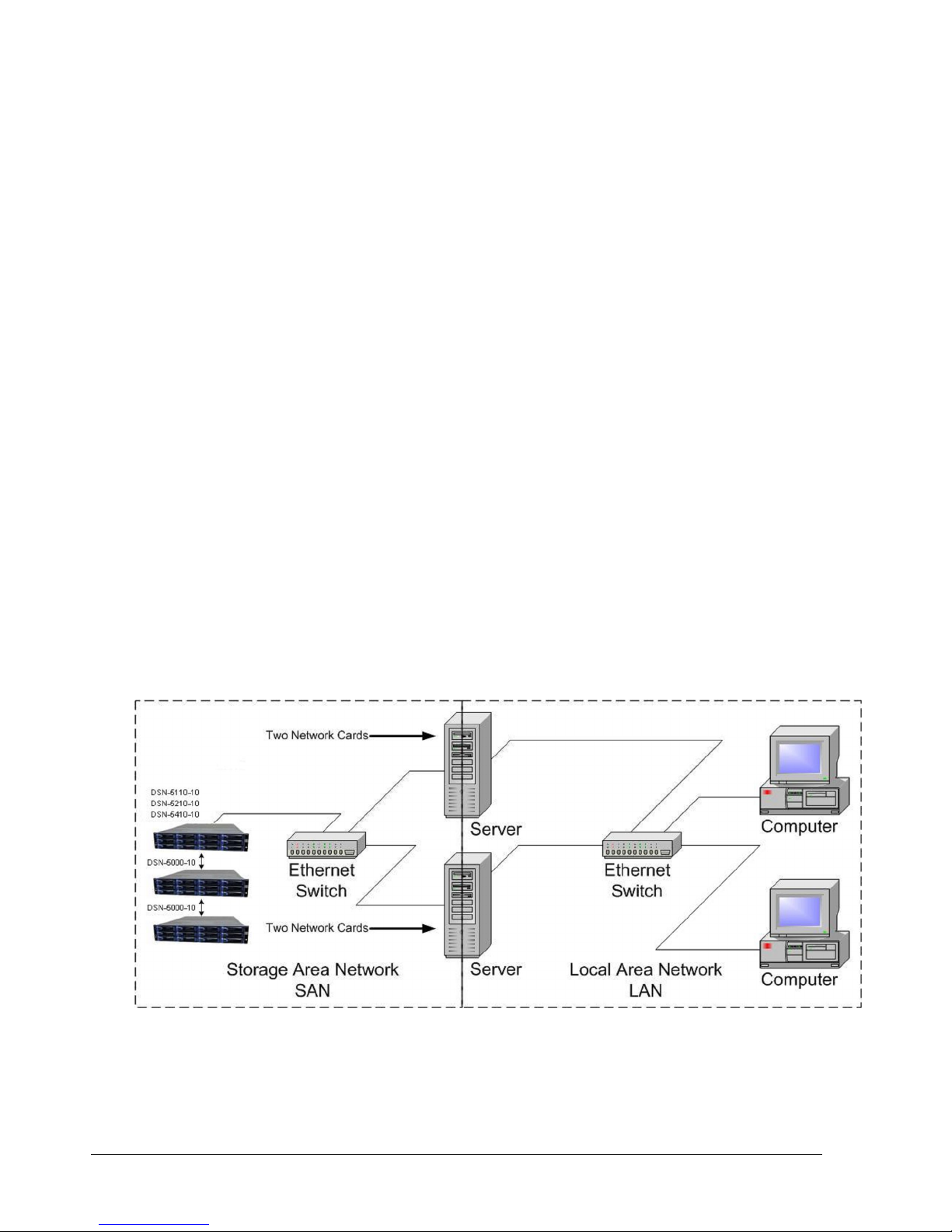
Figure 1-1 shows a typical xStack Storage system configuration. The Storage Area Network
(SAN) shown is an Ethernet network used solely for exchanging data between the customer's
servers and the xStack Storage system. The Ethernet bandwidth used by the servers
exchanging data with the xStack Storage system can be very high. Using a separate Ethernet
to act as a SAN keeps that data from interfering with the customer's existing LAN and
improves security.
Figure 1-1. Storage System Diagram
2 Chapter 1 Introduction

The xStack Storage system performs its virtualization task by presenting volumes that the
servers see as disks or drives or SCSI Logical Units, depending on the server operating
system’s terminology. Volumes are created by organizing blocks of storage from the drives.
iSCSI is an end-to-end storage block protocol that makes it possible to transfer storage data
reliably over any IP-based network, including the Internet. The iSCSI drafts and RFCs are
published by the IETF, but based on the SCSI specifications from the ISO's Technical
Committee Ten (T10), the ANSI-accredited body responsible for developing and maintaining
the core SCSI standard. To the committee, iSCSI is another SCSI transport and just as
officially sanctioned (though technically it's a superset of SCSI, providing additional
functionality through unique commands and data formats used for secondary services such as
authentication).
From the network's perspective, iSCSI is just another service that runs over TCP/IP. It can
use the same networking stack as other applications, with clients requesting data from
servers. The main difference is that its function is more specialized. Whereas other Layer 7
protocols such as SMTP are agnostic toward the technologies used at their endpoints, iSCSI is
designed as a way to extend an existing storage technology across IP networks.
For iSCSI purposes, the SCSI protocol is conceptually similar to TCP/IP's client/server
architecture. Every SCSI link involves a host adapter, called an initiator, and a storage
device, called a “target.” The customer's server will act as the initiator and the xStack
Storage system will act as the target. Traditionally, a local SCSI bus connects a single initiator
to up to seven targets, but a SAN allows an unlimited number of each. The initiator's iSCSI
stack packs SCSI commands and data into IP packets, which are then unpacked by the target
for processing as if they had originated locally.
The iSCSI protocol defines two types of iSCSI Nodes:
The initiator node
The target node
The iSCSI initiator node consists of an initiator name and a set of properties. The server’s
operating system provides software to define and configure its iSCSI initiator node. The
xStack Storage system serves as one or more iSCSI target nodes and automatically assigns
target node names using the standard naming convention defined in the iSCSI protocol.
The xStack Storage system provides the customer a method to create Volumes. Each Volume
is a unit of storage of a specific size with a RAID organization, as described later in this
document. Every volume creation automatically includes the creation of an iSCSI target
node; i.e. there is a one-to-one relationship between iSCSI Target Nodes and Volumes in an
xStack Storage system. An iSCSI target node name is automatically created by the xStack
Storage system using the standard naming convention with the Volume Name in a wellknown position in that name. The xStack Storage system manages initiator access to a
target node as part of volume management. For example, the customer grants an initiator
access to a target node by granting access to the Volume. The server (iSCSI initiator) can
find its storage by finding a known volume name in a list of discovered target node names.
1.3 Storage Pools and Drives
Storage space is managed on the xStack Storage system through storage pools. The
placement of a drive in a storage pool controls the way that drive can be used. There are
four types of storage pools (see Table 1-1).
xStack Storage Management Center Software User’s Guide 3
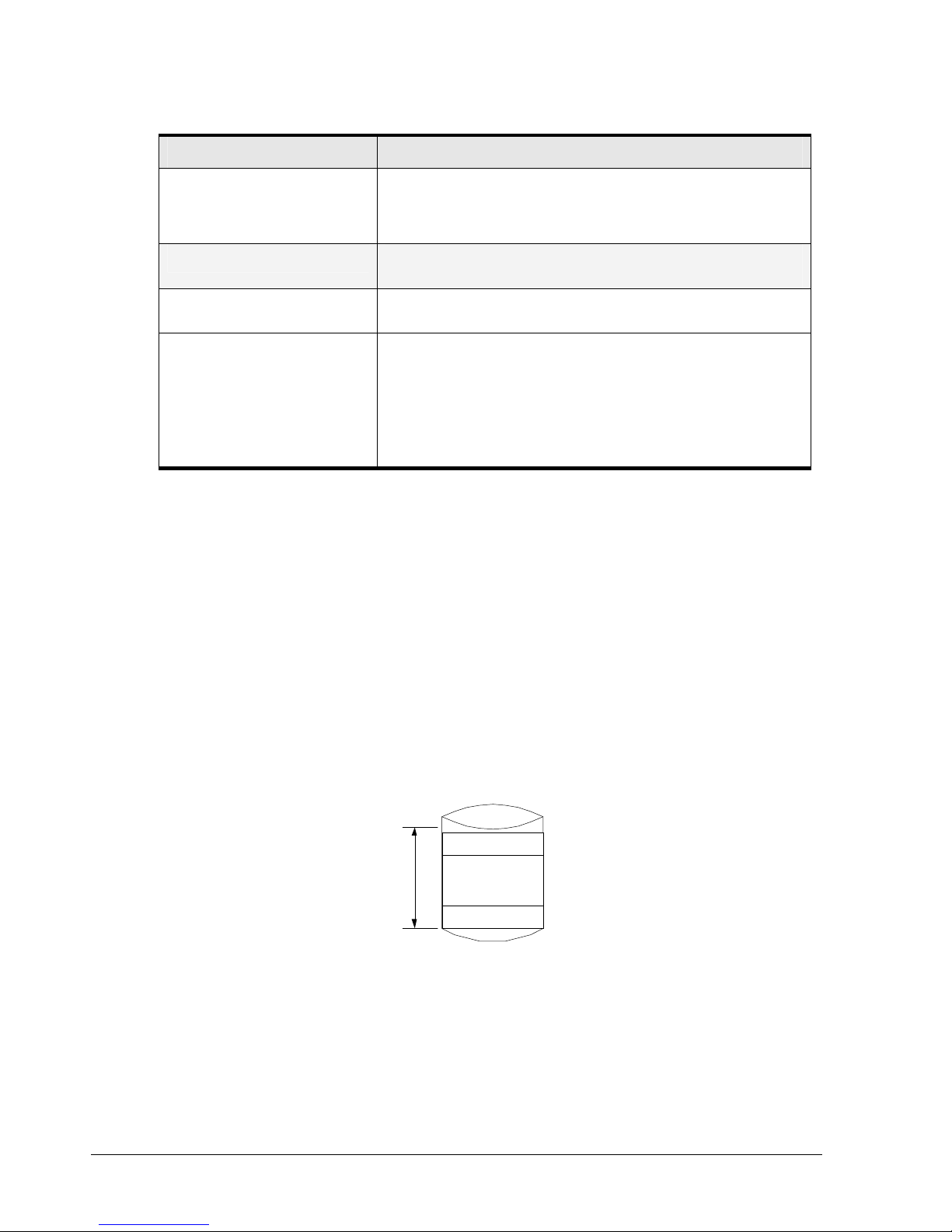
Table 1-1. Types of Storage Pools
0
Storage Pool Usage
Available Pool Disk drives available for use, but with no data stored on them at this time. A
Base Pool Disk drives currently being used to hold Volume data or ready to be used to hold
Spare Pool A drive that can only be used in case of a failure of a drive in the Base Pool. A
Unusable Pool Two types of drives appear in the Unusable Pool:
When a new system is installed, all new drives are placed in the Available Pool. The drives
remain in the Available Pool until they are needed for use in a volume.
1.4 Volumes
A volume is a set of blocks of storage that are organized and presented for use by a
customer’s server (an iSCSI initiator node). Every volume must be associated with a storage
pool, which limits the drives that can be used to hold data for that Volume (only drives in
that pool can be used for this volume). Only drives in the Base Pool can be used for volumes.
drive in the Base Pool will be used in the creation of a new Volume any time it is
required. That drive is automatically moved to the Base Pool at that time with no
manual interaction.
volume data.
drive becomes a Spare only when a customer administrator so designates.
Drives not available for use either because they have already failed and have
not been removed from the enclosure
Drive inserted into the xStack Storage system that were previously used by an
xStack Storage system. Such a drive can be Initialized by the Administrator to
make the drive available for use (which automatically moves the drive to the
Available Pool)
The iSCSI initiator node sees the volume as a contiguous series of numbered blocks in the
same way that it would see the storage space on a single disk drive. The xStack Storage
system constructs a volume from extents, where each extent is a block of storage from a
single drive. A volume typically consists of extents from several drives. A volume of n blocks
is shown in Figure 1-2.
Extent 1
n-1
Extent x
Volume
Figure 1-2. Internal Structure of a Volume
Volumes can be organized in several ways (see Table 1-2)
4 Chapter 1 Introduction

Table 1-2. Ways to Organize Volumes
Organization Definition Redundant Striped Storage Cost
JBOD One copy of the data is written to the selected Extents. No No 1x
Mirror Two copies of all data are written to independent
Extents.
Stripe Distributes one copy of the data among several drives
to improve the speed of access.
Stripe Mirror Distributes the data among several drives and then
keeps a mirror copy of the blocks on each drive
Parity Distributes one copy of the data among several drives
and adds parity blocks spread throughout the volume to
protect against the loss of any single drive.
Yes No 2x
No Yes 1x
Yes Yes 2x
Yes Yes x + 1
For organizations that are striped, the data distributed among multiple drives is organized in
a series of “stripes”. Each stripe consists of a fixed number of blocks on each drive. The
fixed number of blocks used on each drive is called a “chunk.” This can be viewed as an
array where each row is a stripe and each column is a drive. The term “Member” is defined
as the number of columns in this array. The xStack Storage system can allocate the required
space very flexibly (i.e., an entire member does need to reside on a single drive). Within
each member, extents can be obtained from as many drives as necessary.
Organizations that are redundant provide protection against loss of data in the event of a
failure of any one drive. This adds a storage cost in that some storage will be used for
redundancy rather than for customer data. Redundancy requires that the volume data be
stored on separate drives, so that data integrity is maintained in the event of a drive failure.
For a parity organization, the xStack Storage system distributes the volume into the array
described for a stripe organization, and reserves one chunk from each stripe to hold the
parity information. The parity information provides redundancy without having to keep a
complete copy of the data. If any single drive fails, the parity calculation mechanism can be
applied to the data on the remaining drives to provide full access (reading and writing) of all
data.
Further, the parity calculation mechanism can be used to recreate the data with fresh parity
protection onto a new drive to re-gain redundancy. However, this protection comes at a
cost: the storage requirement for the volume is increased by one member. For example, if a
10 GB striped volume was distributed among four members, each member would need 2.5
GB of space. To make a parity volume of 10 GB using four members, for instance, each
member would need 3.33 GB of space: one chunk in each stripe would be used to hold
parity. In other words, to hold the space for parity in a 4-member volume, the xStack
Storage system needs to use 1/3 more space than the initiator can access. From another
point of view, 1/4 of the space used by that volume is not available to the initiator. The 10
GB volume can also be created using 2.5 GB members if five members are used.
As a result, the additional storage cost for a parity volume of four members is 25% (i.e., 25%
of the space is not user data, but redundancy data). For a 5-member parity volume, the
additional cost is 20%.
For a mirror organization, the xStack Storage system divides the volume into two members,
each of which contains one full copy of the data. Each member must be allocated on
separate drives. The cost of a mirror volume is that data must be stored twice (i.e., for a
volume of size x bytes, the xStack Storage system needs 2x bytes, or 100%).
For a stripe mirror organization, the xStack Storage system distributes volume into
members, as in a striped organization, and then doubles the number of members to allow for
the second data copy. As in a mirror organization, the storage cost is double.
xStack Storage Management Center Software User’s Guide 5

For each volume, the xStack Storage system must determine the organization and the size of
the volume. For striped organizations, the xStack Storage system must further determine the
chunk size, and the number of drives across which the data is to be divided.
There are two ways to create a volume in an xStack Storage system:
Automatically: You can answer questions about the required redundancy, size, and usage
characteristics of the volume. The storage system then determines the remaining
parameters needed to allocate the storage space and create the volume.
Manually: You can select the organization and all other parameters described above and
either selects the drives that can be used for the volume or lets the storage system
select the drives. The storage system then finds the storage space on the given drives to
allocate and create the Volume.
Disk space is assigned to a volume in extents. The extents that make up a volume can be
seen on the iStor Management Console. The extents are organized into members. The
definition of a member varies with the organization:
For a striped organization, a member is defined above.
For a mirror organization, there are two members, one for each copy of the data.
A stripe mirror organization has a member for each stripe, as defined above, plus a
second member (for each stripe) to hold the data copy. Therefore, if a stripe mirror
organization has x stripes, it has 2x members.
1.5 Tasks
The xStack Storage system can automatically or at your demand perform activities that take
time and consume the controller’s resources. You can control, to some degree, when tasks
are performed. You can suspend and resume any task. Some tasks can be cancelled and
some can be scheduled on a recurring, periodic interval. The xStack Storage system can
perform the tasks described in the following sections.
1.5.1 Initialize a Parity Volume
Some volume organizations (e.g., parity) require Initialization. The Initialization task
performs this action. This task can be performed while an initiator is accessing (reading and
writing) data. An Initialization task can be suspended and resumed, but cannot be cancelled.
1.5.2 Rebuild a Volume
When a drive fails, every redundant volume that occupied space on that drive can be
rebuilt.
For mirror protection, data can be copied from the remaining copy.
For parity protection, data can be recreated from the remaining data and parity
information.
Volume rebuilds look for a spare or available drive that is the same type (SAS/SATA/SSD) and
capacity as the drive that failed or was removed. If a matching drive cannot be found, the
system will attempt to allocate any other similar type drive from the spare or available pool
for the rebuild. If a similar drive type is not available, the system will use any spare or
available drive, even if it is a different type. Finally, if there is no spare or available drive,
the system will use any available capacity on any drive that is already in use. To reserve a
drive as a spare, select the drive in the Physical Storage View, and click on the "Reserve as
Spare" item.
6 Chapter 1 Introduction

If a replacement drive is found, then the storage system performs one Rebuild task for each
extent on the failed drive rebuilding that extent onto 1) the same position it previously
occupied on the failed drive, if the replacement drive is the same size or larger, or 2) the
next available space on the replacement drive, if the replacement drive is smaller than the
failed drive. So, if the replacement drive is the same size or larger than the failed drive,
the replacement drive appears to be a “clone” of the failed drive. If the replacement drive
is smaller than the failed drive, then the replacement drive contains the same extents in the
same order, but with the empty space removed from between the allocated extents.
If no replacement drive could be found, then each extent on the failed drive is rebuilt
individually, if possible, onto any space that can be found in 1) any drive(s) in the Base Pool,
2) one or more drives in the Spare Pool, or 3) one or more drives in the Available Pool.
A Rebuild task can be suspended and resumed, but cannot be cancelled.
1.5.3 Scan a Volume
You can scan a volume for media errors by starting a Volume Scan task. This task reads every
block in the volume to ensure there are no errors. If there are errors, this task fixes them if
possible. The system administrator can cancel, suspend or resume a Media Scan task. You
can also schedule a Volume Scan for a future time and/or at a recurring interval.
1.5.4 Grow (Expand) a Volume
You can increase the size of a volume. If the volume’s organization requires initialization,
the initialization of the new storage capacity is performed with a Grow task. A Grow task
can be suspended and resumed, but it cannot be cancelled. An initiator can access the new
space in a volume while the Grow task is being performed.
1.5.5 Reconfigure a Volume
The xStack Storage system allows Administrators to change the RAID characteristics and/or
size of an existing volume. When you reconfigure a volume, you can specify the RAID
organization, hard disk drives to be used, stripe width, and size of the reconfigured volume.
In most cases, to perform the reconfiguration, the storage system must copy all the data
from the disk space originally allocated to the Volume onto new disk space. In general,, a
good rule of thumb to follow is to have sufficient capacity to support the total capacity of
the current and new volumes. For example, to reconfigure a 100 GB volume to 150 GB, you
should have a total of 250 GB of free disk space available for the period of time that the
Reconfigure operation takes place.
Some reconfigure operations, however, may only need the difference in space free, since
the originally allocated disk space can be reused. This means, that if you’re reconfiguring a
100 GB volume to 150 GB, only 50 GB of free space will be required instead of 250 GB.
A Reconfigure task can be suspended and resumed, but it cannot be cancelled.
1.6 Network Portals
A Reconfigure operation can take a considerable amount of time. The
volume remains usable at its original size during this operation. When a
volume is reconfigured, you can observe the progress of the operation. When
the Reconfigure operation completes, the reconfigured volume can be used
with its new size and RAID organization.
A network portal is a combination of an IP address, a subnet mask, and a port number. In
iSCSI, the standard port is number 3260, which is the port used by the storage system. Each
iSCSI Target Node identifies the network portals through which initiators can access the
storage system.
xStack Storage Management Center Software User’s Guide 7
1.7 VLANs
1.8 LAGs
The xStack Storage system can use a Virtual LAN (VLAN) as a filter to identify the incoming
packets it is to use on each LAG port. For each LAG port on which VLAN is to be enabled, a
VLAN ID must be defined. On a VLAN-enabled LAG port, only packets with the given VLAN ID
will be processed and all outgoing packets will be tagged with that VLAN ID.
The xStack Storage system manages the physical data ports on the enclosure's back panel
using the concept of LAG ports. In a simple configuration, a LAG port associates a
single Ethernet port (i.e., a physical data port) with a network portal (that defines an IP
address). In this case, which is the default, there are no LAG ports shown on the
Management Console and no management is necessary.
Some server Operating Systems can aggregate multiple Ethernet ports into a LAG port and
provide increased bandwidth. For example, aggregating two GbE ports could, theoretically,
provide up to 2 Gb/s of throughput. Should a customer wish to utilize this feature, the
Management Console can be used to replace the standard one-to-one relationship of
Ethernet port to Network Portal with a LAG.
LACP protocols are not supported. Static LAG configurations are the only
supported option.
1.9 iSCSI Target Nodes
An iSCSI target node is the method of providing a permissible access to storage on an xStack
Storage system. One target node is automatically generated for each volume. The target
node name includes the volume name with any spaces and other special characters removed.
Access to that volume is granted to an initiator via its iSCSI Initiator Node name. Optionally,
a CHAP secret can be specified for a volume for additional security authentication.
1.10 iSCSI Log-In, Sessions and Connections
When an iSCSI initiator node needs access to the volumes in an xStack Storage system, it
must log in to the target node associated with that volume. When the log in is accepted, an
iSCSI session and an iSCSI connection is established. An initiator can log in to the same target
node a second time, creating a second iSCSI connection within the original iSCSI session.
1.11 Multiple Connections per Session
An initiator can log into a target more than once to establish multiple connections for a
single session. Multiple connections can be used to increase bandwidth and provide
redundancy.
8 Chapter 1 Introduction

Chapter 2 Overview of the Management Center Software
The right management software can help you enhance the performance and functionality of
your storage investment. The xStack Storage Management Center from D-Link Inc has been
designed and optimized from the ground up to deliver the command and control foundation
you need to efficiently manage your xStack Storage infrastructure.
The xStack Storage Management Center is an intuitive Java-based graphical application that
provides anytime, anywhere access and control to your xStack Storage arrays. By providing
increased visibility with unified views of your storage environment along with powerful
feature-rich offerings and point-and-click simplicity, the xStack Storage Management Center
empowers you to maximize your investment in xStack Storage arrays while enjoying lower
total cost of ownership.
This User’s Guide describes how to use the xStack Storage Management Center to configure,
provision, and manage the storage on xStack Storage arrays. It includes an overview of the
xStack Storage Management Center, a description of its user interface, and step-by-step
instructions for performing configuration and management activities.
2.1 Key Features
The following list summarizes a few key features of the xStack Storage Management Center:
Feature-rich embedded IP-based Management Center lets you install, configure, and
maintain all of your online network storage with unparalleled ease and flexibility
Easy wizard-based installation slashes configuration time allows you to focus your
valuable resources on supporting users instead of maintaining equipment
Remote configuration and monitoring of xStack Storage arrays
For the latest information about hardware and software supported by your
D-Link DSN iSCSI SAN Array, please consult the Interoperability Matrix found
on the D-Link Systems Inc Web site: http://www.dlink.com
xStack Storage Management Center Software User’s Guide 9

2.2 Compatibility and Minimum System Requirements
Running the xStack Storage Management Center requires a host computer system connected
to the management port of an xStack Storage array. The host system must have an installed:
Network-interface card (NIC) initially configured for the same Internet Protocol (IP)
subnetwork (192.168.1.x) as the xStack Storage management port.
Web browser (Windows Internet Explorer v6.0 or later, FireFox 2.0 on Linux)
Version of the latest Java Runtime Environment (JRE). If the latest version of JRE is not
installed, you will be able to download it if the host system has Internet access. The
minimum version of JRE is v1.6.0.0.
In addition:
The xStack Storage arrays must be powered-up and the Ready Light on the front panel of
all arrays must be ON (green).
If your management host has a firewall, see section 9.3 for best practices on using your
xStack Storage solutions in a firewall environment.
2.3 Understanding the Basics
The xStack Storage Management Center is a graphical Web-based interface used to perform
centralized storage configuration, management, administrative, and network activities for
one or more xStack Storage systems (see Figure 2-1). These activities are performed in their
own screens (or “views”).
The xStack Storage Management Center supports the following four views:
Volume View – lets you view, configure, and manage storage volumes.
Physical Storage View – lets you view and manage xStack Storage hard disks.
System Administration View – lets you perform system administrator activities such as
setting up user accounts, upgrading software, and selecting an xStack Storage battery
policy.
Network Settings View – lets you view and configure the settings for the management
and iSCSI data ports.
For your convenience, there are a number of ways to move from one view to another:
Click commands on the pull-down View menu.
Click icons in the View panel.
Click buttons in the toolbar.
The information shown in the views is a point-in-time snapshot. To update the information
shown, either click Refresh All on the View menu or press the F5 key.
10 Chapter 2 Overview of the Management Center Software
2.3.1 Understanding the User Interface
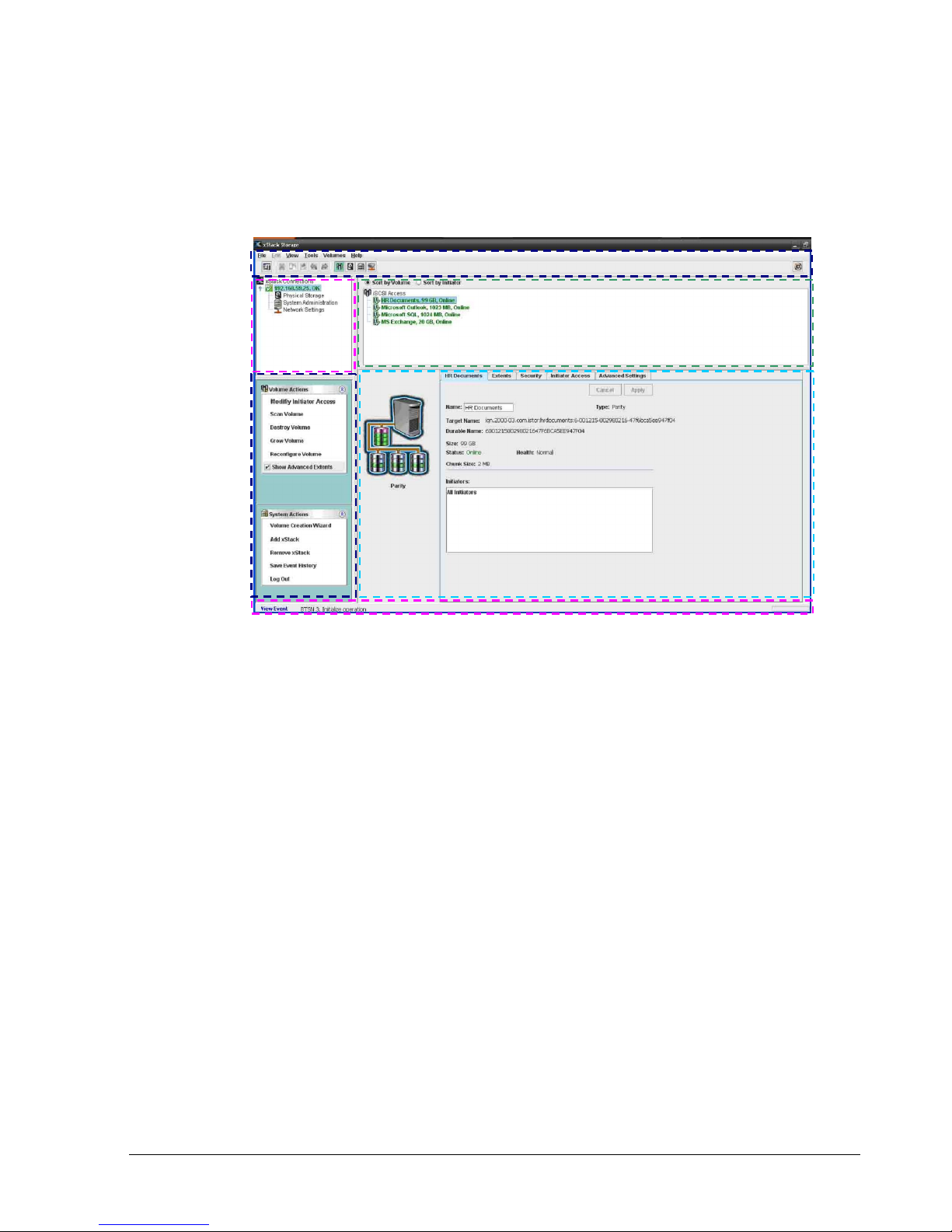
Figure 2-1 shows the different areas of the xStack Storage Management Center main window.
The following sections describe these areas. For a summary of the commands and menus on
the menu bar, refer to Appendix A.
Menu Bar
and Toolbar
View Panel
Action Panel
Status Bar
Figure 2-1. xStack Storage Management Center Main Window
2.3.2 Menu Bar and Toolbar
The menu bar appears at the top of the xStack Storage Management Center main window
(see Figure 2-2). The menu bar contains commands for performing activities relative to the
current view. In the Volume View shown in Figure 2-1, the Volumes menu provides
commands for managing volumes. Menus and commands change when you switch views. If
you switch from Volume View to Physical Storage View, the Volume menu changes to
Storage and all the volume-related commands in the Volume menu change to commands
relevant to managing the physical storage on the xStack Storage.
Main Display
Detail Tabs
The toolbar appears below the menu bar and provides buttons for frequently performed
activities in the current view. If you place the pointer over a button in the toolbar, a tooltip
identifies the button’s function. Figure 2-3, shows the tooltip that appears when the pointer
is moved over the Volume View button on the toolbar. The buttons displayed on the toolbar
change depending on the current view. If you prefer to hide the toolbar, uncheck Show
Toolbar on the View menu.
Figure 2-2 shows an example of how the menu bar and toolbar appear in the Volume View.
xStack Storage Management Center Software User’s Guide 11
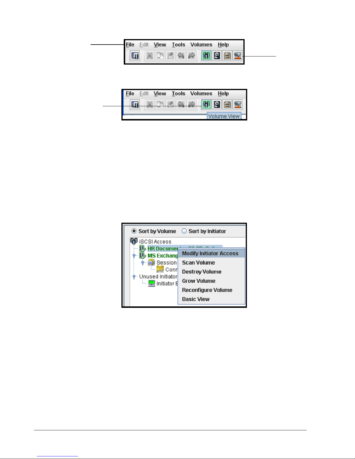
Menu bar
Volume View
Button
2.3.2.1 Shortcut Menu
The previous section explained how the menus, commands, and toolbar can be used to
perform activities. As an added convenience, some tasks can also be performed by pressing
the right mouse button and clicking an option from a shortcut menu that appears.
In Volume View, for example, selecting a volume in the Main Display and pressing the right
mouse button displays the shortcut menu in Figure 2-4. You can then select an option from
the shortcut menu to perform the desired task.
Toolbar
Figure 2-2. Menu Bar and Toolbar
Figure 2-3. Tooltip
Figure 2-4. Shortcut Menu for Volume View Main Display
12 Chapter 2 Overview of the Management Center Software
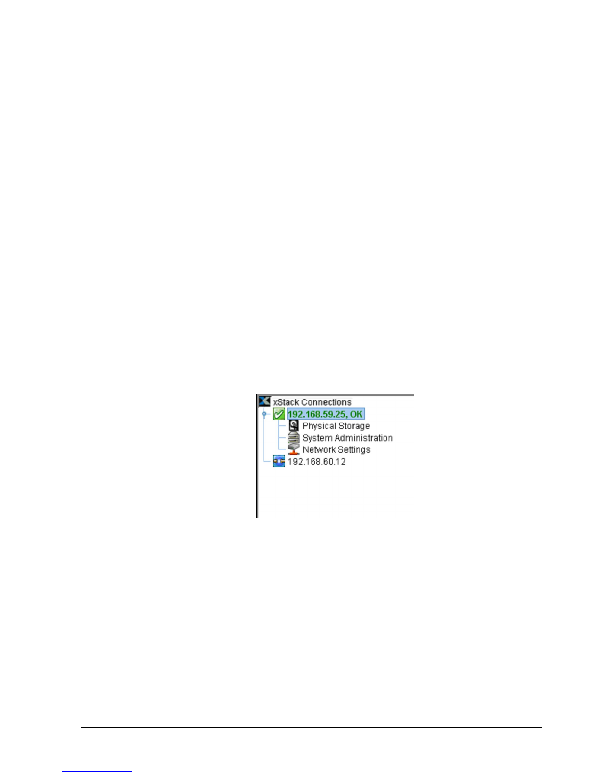
2.3.3 View Panel
The View panel appears below the toolbar. The View panel shows the IP address of each
xStack Storage that has been added to the Management Center (an xStack Storage must be
added to the console in order to be managed by it). In Figure 2-5, two xStack Storage
systems have been added to the Management Center, one with an IP address of
192.168.59.25 and another with the IP address 192.168.60.12.
While you can add many xStack Storage systems to the Management Center, the console lets
you access one xStack Storage at a time. To identify the xStack Storage that is currently
being managed, the IP address of the currently managed system appears in a box along with
color-coded icons that indicates its operating status. In the View panel in Figure 2-5, the
xStack Storage corresponding to IP address 192.168.59.25 is being managed. The checkmark
and OK next to this IP address, and the green color coding of the IP address itself, indicate
that this xStack Storage is operating normally.
When the IP address of the currently managed xStack Storage is highlighted, the Volume
View is displayed. Below the IP address of the currently managed xStack Storage are links
you can click to display the other console views for that array. In Figure 2-5, clicking
Physical Storage displays the Physical Storage View of the xStack Storage corresponding to
IP address 192.168.59.25.
If you add an xStack Storage system to the Management Center (described in section 8.1),
you can log in to that system by clicking its IP address in the View pane. In Figure 2-5,
clicking the IP address 192.168.60.12 will display the login page for the xStack Storage
associated with that IP address.
Figure 2-5. View panel
xStack Storage Management Center Software User’s Guide 13
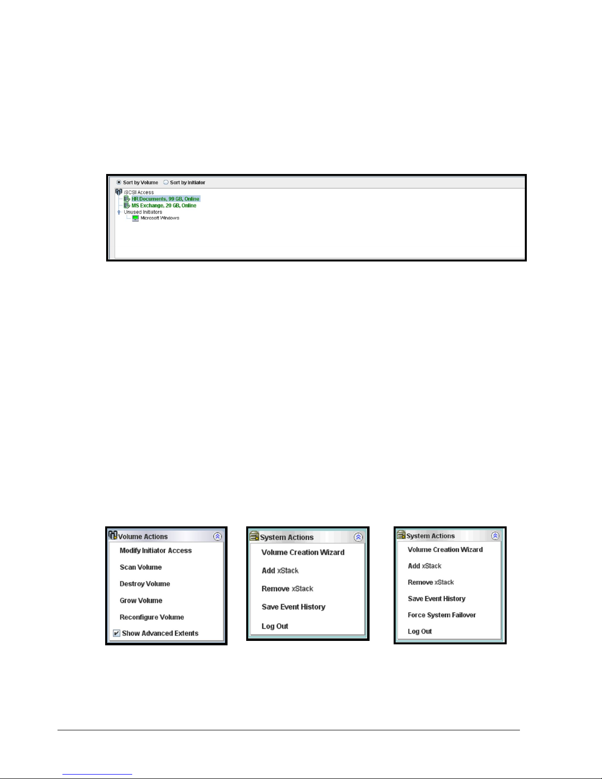
2.3.4 Main Display
The Main Display appears to the right of the View panel. The Main Display shows information
relevant for the current view. For example, when the Volume View is displayed (as shown in
Figure 2-6), the Main Display provides radio buttons for sorting the information shown by
volume name or iSCSI initiator, along with the volumes and iSCSI initiators associated with
the xStack Storage being managed.
2.3.5 Action Panels
Figure 2-6. Main Display in Volume View
Below the View panel are action panels. Most views show two action panels.
The top panel contains actions relevant to the current view and any item selected in the
Main Display. The top panel acquires its name from the current view. In Volume View, for
example, the top panel becomes the Volume Actions panel and contains actions associated
with volumes. If you switch to Physical Storage View, the tops panel changes to the Drive
Actions panel and displays actions related to drives. If there are no actions available for the
current view, such as in System Administrator View, the top panel disappears.
There are times when the top panel and the Detail Tabs below the Main Display work
together. In Volume View, for example, clicking Show Advanced Extents in the Volume
Actions panel (see Figure 2-7) displays advanced extent information in the Extents tab.
The System Actions panel appears below the top panel. The System Actions panel contains
either five or six actions (depending on whether the xStack Storage system is capable of
supporting single or dual controllers) and is displayed for all views.
Figure 2-7. Volume Actions and System Action Panels
14 Chapter 2 Overview of the Management Center Software
2.3.6 Detail Tabs
Detail Tabs appear below the Main Display. When you display a view, activities and
information associated with the selected item in the view appear in these tabs in the Detail
Tabs area. These tabs will change when you switch views or select a different item from the
current view. In the Volume View, the tabs in Figure 2-8 appear, allowing you to view and
perform volume-related activities.
2.3.7 Status Bar
The status bar appears at the bottom of the main window. If an action (such as an alert or
event) requires your attention, it appears as a clickable link on the left side of the status
bar. On the right side of the status bar is an activity indicator that moves from side to side
to indicate when activity is being performed; otherwise, the activity indicator sits dormant.
For users who prefer the status bar to be hidden, uncheck Show Status Bar on the View
menu.
Clickable Event Link
2.4 Getting Help
The xStack Storage Management Center provides a comprehensive online help system that is
available by clicking the Help button on the toolbar (see Figure 2-10). The help system is
optimized for fast access and contains information about every component in the xStack
Storage Management Center. When you click the help button, a question mark gets
appended to the pointer. You can then click an area on the main window to display a help
topic for that area. Help is also available for xStack Storage wizards by pressing the F1 key.
Figure 2-8. Detail Tabs in Volume View
Figure 2-9. Status Bar
Activity Indicator
xStack Storage Management Center Software User’s Guide 15
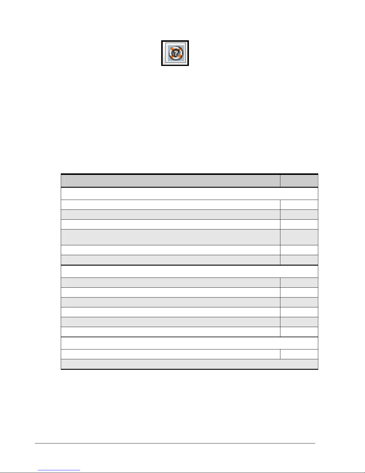
Figure 2-10. Help Button
2.5 READ THIS SECTION - If You Read Nothing Else In This Guide
Table 2-1 identifies the tasks that can be performed using the xStack Storage Management
Center. These tasks are organized into three groups:
Required tasks that all users must perform
Recommended tasks that D-Link Networks recommends that you perform
Optional tasks that are suggested but not required to use the xStack Storage
Table 2-1. xStack Storage Management Center User Tasks
Task See Section
Required Tasks
1. Log in to the xStack Storage Management Center for the first time. 3.1
2. Complete the Start-up Wizard (first-time login only). 3.1.1
3. Change the default admin login password. 3.4.1
4. Set up users (if users other than the administrator will be accessing the xStack Storage Management
Center).
5. Create one or more volumes. 4.2
6. Grant access to all initiators. 4.3.1
Recommended Tasks
1. Save the configuration file. 6.2.5
2. Grant individual iSCSI initiators access to volumes. 4.3.1
3. Check drive status periodically. 5.1
4. Check the drives’ SMART status (SATA drives only). 5.3.3
5. Set up one or more spare drives. 5.2.3
6. Change the hostname to simplify for identification and troubleshooting. 7.2
Optional Tasks
1. Make sure the Battery Policy setting is correct for your application. 6.2.11
All of the other activities described in this document are optional.
3.4.2
16 Chapter 2 Overview of the Management Center Software
Chapter 3 Getting Started
This chapter describes how to get started using the xStack Storage Management Center. The topics
covered in this chapter are:
Section 3.1, Connecting and Logging In
Section 3.2, Setting the System Date and Time
Section 3.3, Customizing the Date and Time
Section 3.4, Configuring User Accounts
Section 3.5, Logging Out
Section 3.6, Exiting the xStack Storage Management Center
Section 3.7, Shutting Down the xStack Storage Array
Before proceeding, be sure all the minimum system requirements in
section 2.2 have been met.
xStack Storage Management Center Software User’s Guide 17
3.1 Connecting and Logging In
After confirming that the minimum system requirements in section 2.2 have been met, use the
following procedure to connect and log in to the xStack Storage Management Center.
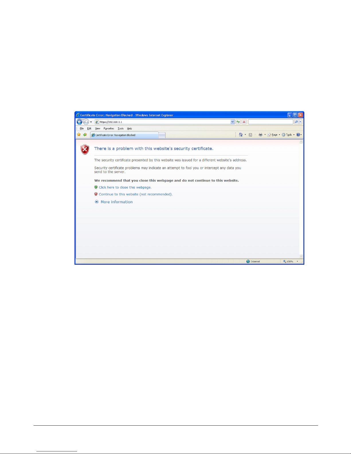
1. Start a Web browser on the PC connected to the xStack Storage management port.
2. In the browser’s address bar, type the following default IP address: https://192.168.1.1
and press Enter. If you receive a browser certificate warning prompt as shown in Figure 3-1,
select the “Continue to this website” option to proceed.
3. One of the following actions occurs:
– For your initial login, the Start-up Wizard appears and you should proceed to
section 3.1.1.
– For all subsequent logins, the home page appears and you should proceed to section 3.1.2.
3.1.1 Using the Start-up Wizard
The xStack Storage Management Center provides a straightforward, easy-to-use Start-up Wizard
for the initial configuration and setup of your storage environment. The Start-up Wizard
incorporates a series of intuitive point-and-click pages that start automatically, guiding
administrators through the first-time setup.
The Start-up Wizard greets you with the Welcome page in Figure 3-2.
Figure 3-1. Certificate Warning
18 Chapter 3 Getting Started
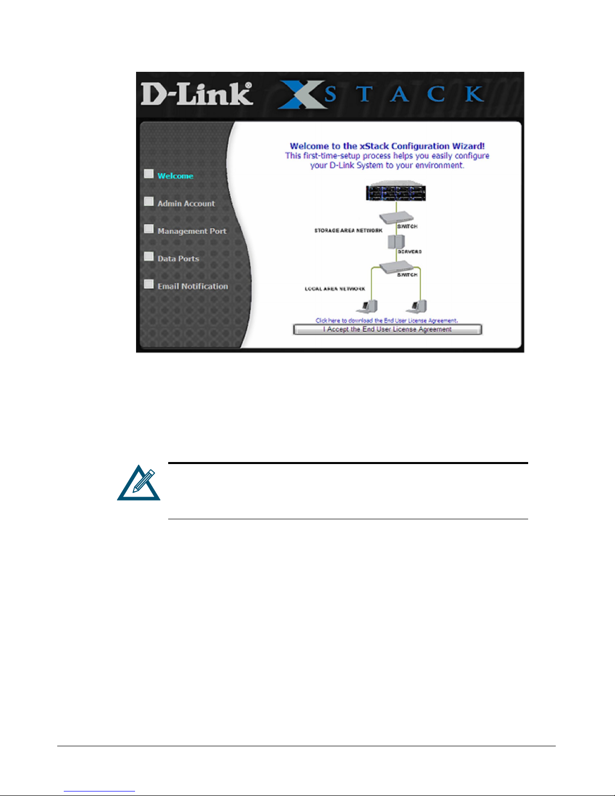
Figure 3-2. Welcome Page
From the Welcome page, perform the following steps to set up the xStack Storage system for
initial use.
1. Click the I Accept the End User License Agreement button on the Welcome screen. The
Admin Account page in Figure 3-3 appears.
You must accept the End User License Agreement to proceed with the Startup Wizard. To download the End User License Agreement to your computer,
click Click here to download the End User License Agreement on the
Welcome screen.
xStack Storage Management Center Software User’s Guide 19
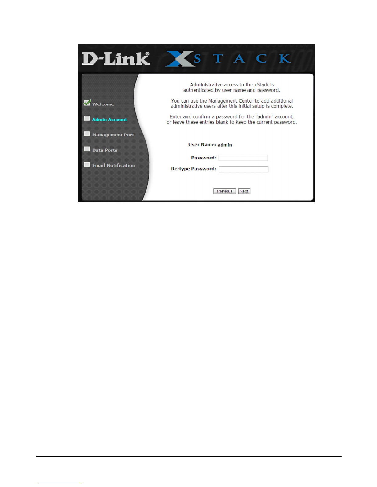
Figure 3-3. Admin Account Page
2. The Admin Account page allows you to set the password for the administrator account.
(Additional administrative accounts can be set up after completing the initial Start-up
Wizard.) If you want to change the default password, type a case-sensitive password in the
Password field and then retype the same password in the Re-type Password field. For
security, each typed password character appears as a bullet (). Record the admin password in
Table C-6.
3. Click Next to continue. The Management Port page appears (see Figure 3-4).
20 Chapter 3 Getting Started
 Loading...