

Page 1

DSL-300
ADSL Ethernet Modem
User’s Guide
Second Edition (April 2001)
6DSL300...02
Printed In Taiwan
Page 2

Page 3

TABLE OF CONTENTS
ABOUT THIS USER’S GUIDE........................................................................................................................... 1
BEFORE YOU START............................................................................................................................................1
ADSL Service........................................................................................................................................1
INTRODUCTION.................................................................................................................................................2
WHAT IS ADSL?.................................................................................................................................................2
MODEM DESCRIPTION AND OPERATION ..............................................................................................................3
PRODUCT FEATURES ........................................................................................................................................... 3
G.hs (Auto-handshake)..................................................................................................................................3
High Performance..........................................................................................................................................3
Ethernet Ready...............................................................................................................................................3
ATM (Asynchronous Transfer Mode).............................................................................................................3
Precise ATM Traffic Shaping.........................................................................................................................3
Easy Installation.............................................................................................................. .............................. 3
FRONT PANEL......................................................................................................................................................4
REAR PANEL........................................................................................................................................................ 4
LED INDICATORS................................................................................................................................................ 5
UNPACKING .........................................................................................................................................................5
HARDWARE INSTALLATION..........................................................................................................................6
CONNECT THE POWER .........................................................................................................................................6
CONNECT ADSL LINE .........................................................................................................................................6
CONNECT ETHERNET LAN TO MODEM ...............................................................................................................7
PC/SERVER TO MODEM CONNECTION.................................................................................................................8
SOFTWARE INSTALLATION...........................................................................................................................9
INSTALL DSL-300 CONFIGURATION UTILI TY.......................................................................................................9
CONFIGURE THE MODEM ..................................................................................................................................13
MODEM DIAGNOSTICS.......................................................................................................................................16
Advanced Diagnostics..................................................................................................................................18
CONTACTING TECHNICAL SUPPORT.......................................................................................................20
OFFICES.......................................................................................................................21
TECHNICAL SPECIFICATIONS....................................................................................................................23
CREATING A NEW PASSWORD....................................................................................................................24
DSL-300 FIRMWARE UPGRADE UTILITY..................................................................................................25
Page 4

Page 5

DSL-300 ADSL Ethernet Modem User’s Guide
About This User’s Guide
This user’s guide provides instructions on how to install the DSL-300 ADSL
Modem and use it to connect a PC or Ethernet LAN to the Internet or a remote
LAN. For the sake of simplicity, this document uses the terms Modem (first letter
upper case) to refer specifically to the DSL-300 ADSL Modem, and modem (first
letter lower case) to refer to all such devices including the DSL-300.
This guide assumes that the reader has some familiarity with Ethernet networks,
networking devices, and the TCP/IP suite of protocols.
Before You Start
For the smoothest possible installation process, please read and make sure you
understand all the prerequisites for proper installation of your new Modem. Have
all the necessary information and equipment on hand before you begin.
ADSL Service
In order to use the Router you must first have ADSL service establi shed with an
ADSL service provider, usually your local telephone company, or an Internet
service provider (ISP). Contact your local telephone company for information on
the availability of ADSL service in your area.
Micro-filters
Since ADSL and telephone services share the same copper wire to carry their
respective signals, a filtering mechanism may be necessary to avoid mutual
interference. You will need to install a micro-filter (low pass filter) device for each
telephone that shares the line with the ADSL line. Micro-filters are easy to
install in-line devices, which attach to the telephone cable between the telephone
and wall jack. This device will not affect normal telephone services. Your
telephone company or ADSL service provider will have more information
regarding the use and installation of micro-filters.
VPI and VCI Settings
Your ADSL service provider will provide two numbers, a Virtual Path Identifier
(VPI) and a Virtual Channel Identifier (VCI). You will need to enter these two
numbers during the configuration of the Router.
In order to ensure high quality of service and maximum performance, ADSL
technology employs Asynchronous Transfer Mode (ATM) networks (via the
DSLAM). ATM networks use Permanent Virtual Circuits (PVCs) to establish
end-to-end software defined logical connections. The VPI and VCI are contained
in the ATM cell header. These numbers help manage ATM network connections
and identify logical links formed by PVCs.
For convenient reference, you may want to record the VPI and VCI numbers here,
as well as the MAC (Physical) Address of the Modem.
1
Page 6

DSL-300 ADSL Ethernet Modem User’s Guide
Introduction
ADSL technology is a relatively new technology and may be unfamiliar to the
reader. In this section, we introduce you to ADSL technology and give a brief
description of its key attributes. We also give a general description of the D-Link
DSL-300 Modem and its main features.
What is ADSL?
Asymmetric Digital Subscriber Line (ADSL) is an access technology that utilizes
ordinary copper telephone lines to enable broadband high-speed digital data
transmission and interactive multimedia applications for business and
residential customers. Using existing phone lines means there is no need to add
expensive new fiber-optic cable or line conditioning.
ADSL modems greatly increase the signa l carrying capacity of copper telephone
lines without interfering with regular telephone services. For the ADSL user,
this means much faster data communications and interactive multimedia
capabilities. ADSL devices make it possible to enjoy benefits such as high-speed
Internet access, telecommuting (remote LAN access), collaborative computing,
distance learning, movies on demand and multiplayer video gaming without
experiencing any loss of quality or disruption of voice/fax telephone capabilities.
ADSL provides a dedicated service over a single telephone line operating at
speeds of up to 8 Mbps downstream and up to 640 Kbps upstream, depending on
local telephone line conditions. These conditions are ideal for many user
applications. A secure point-to-point connection is established between the user
and the central office of the local telephone service provider. The user is always
connected thus eliminating dial-up time and simplifying connectivity issues.
D-Link ADSL devices incorporate the recommendations of the ADSL Forum
regarding framing, data format, and upper layer protocols.
2
Page 7

DSL-300 ADSL Ethernet Modem User’s Guide
Modem Description and Operation
The DSL-300 ADSL Ethernet Modem is easy to install and use. The DSL-300
connects to an Ethernet LAN via a standard Ethernet 10BASE-T interface. Your
ADSL connection is made using ordinary twisted-pair telephone line with
standard RJ-11 connectors. Several PCs can be networked in an Ethernet LAN
and connected to the Internet via the Modem.
Product Features
The DSL-300 ADSL Ethernet Modem utilizes the latest ADSL enhancements and
technologies to provide a reliable Internet portal suitable for most small to
medium sized offices.
G.hs (Auto-handshake)
This feature allows the Modem to use either the G.lite, G.dmt or ANSI T1.413
(Issue 2) ADSL connection standards.
High Performance
Very high data transfer rates can be realized with the Modem. Up to 8 Mbps
downstream bit rate using the G.dmt.
Ethernet Ready
The Modem connects to your Ethernet LAN via a standard 10BASE-T Ethernet
port.
ATM (Asynchronous Transfer Mode)
The DSL-300 supports Bridged Ethernet over ATM (RFC 1483).
Precise ATM Traffic Shaping
Traffic shaping is a method of controlling the flow rate of ATM data cells used to
establish the Quality of Service (QoS) on an ATM network.
Easy Installation
The DSL-300 uses a Windows® based graphical user interface (GUI) for easy
installation and management.
3
Page 8
DSL-300 ADSL Ethernet Modem User’s Guide
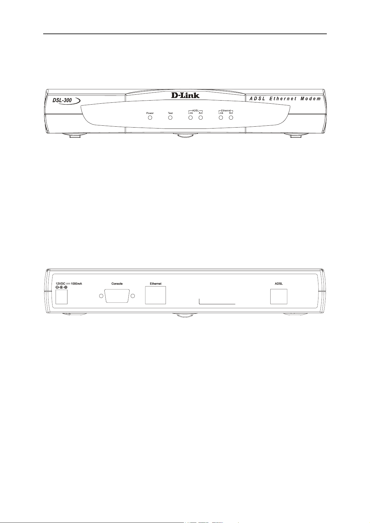
Front Panel
Place the Modem in a location that allows a view of the LED i ndicators shown in
the front panel diagram below.
Front Panel
Rear Panel
The rear panel of the Modem provides access to the power cord connection as well
as the various communication port connections.
Rear Panel
4
Page 9
DSL-300 ADSL Ethernet Modem User’s Guide
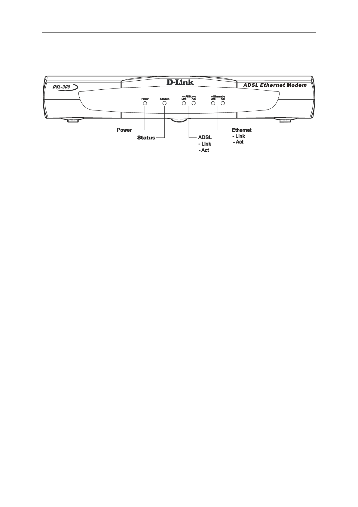
LED Indicators
LED Indicators
The LED Indicators read as follows:
Power Steady green light indicates the unit is powered on.
Status Lights steady green during the ADSL negotiation phase. Once the
connection status has been settled, the light will blink green.
ADSL: Link Steady green light indicates a valid ADSL connection. This will
light after the ADSL negotiation process has been settled.
ADSL: Act Blinking green light indicates an active WAN session.
Ethernet: Link Steady green light indicates a valid Ethernet connection.
Ethernet: Act Blinking green indicates an active Ethernet session.
Unpacking
Open the shipping carton and carefully remove all items. In addition to this
User's Guide, ascertain that you have:
1. DSL-300 ADSL Ethernet Modem
2. DSL-300 tool kit on CD-ROM containing The User’s Guide and the DSL- 300
Configuration Utility software installation program
3. Twisted-pair telephone cable or appropriate connector for ADSL connection
(Use AWG 26 twisted-pair telephone cable where not provided)
4. Straight-through Ethernet cable
5. One AC power adapter suitable for your electric service
5
Page 10

DSL-300 ADSL Ethernet Modem User’s Guide
Hardware Installation
In this chapter you will learn about the various connections you will need to
make in order to use the Modem.
When selecting the location for the Modem be sure to allow room to access the
connections on the rear panel. You will want to place the Modem so that you will
be able to see the LED indicators on the front panel. Allow some space above the
Modem for ventilation to avoid problems with overheating.
Connect the Power
Insert the AC Power Adapter cord into the power receptacle located on the rear
panel of the Modem and plug the adapter into a nearby power source. You should
see the Power LED indicator light up and remain lit. The Test LED should light
for a few seconds and turn off.
Connect ADSL Line
You can use the twisted-pair telephone ADSL cable included with the Modem to
connect to your telephone line. Simply plug one end of the cable into the ADSL
port (RJ-11 receptacle) on the rear panel of the Modem and insert the other end
into the wall jack.
6
Page 11
DSL-300 ADSL Ethernet Modem User’s Guide
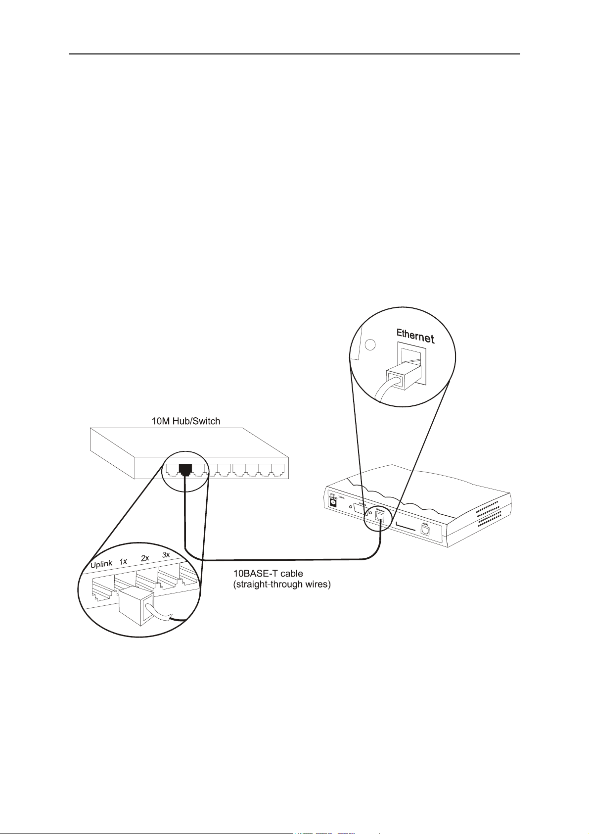
Connect Ethernet LAN to Modem
The Modem may be connected to any 10BASE-T Ethernet LAN. Any connection
to an Ethernet concentrating device such as a switch or hub must operate at a
speed of 10 Mbps only. Use standard twisted-pair cable with RJ-45 connectors.
The RJ-45 port on the Modem is a crossed (MDI-X) port. Follow standard
Ethernet guidelines when deciding what type of cable to use to make this
connection. You should use a normal straight-through cable when connecting the
Modem to a normal (MDI-X) port on a switch or hub. Use a straight-through
cable when connecting it to an uplink (MDI-X) port on a hub or switch. When
connecting the Modem directly to a PC or server use a straight-through cable. A
valid connection will be indicated by the Ethernet Link LED indicator.
The rules governing Ethernet cable lengths apply to the LAN to Modem
connection. Be sure that the cable connecting the LAN to the Modem does not
exceed 100 meters.
Ethernet LAN to Modem Connection
7
Page 12
DSL-300 ADSL Ethernet Modem User’s Guide
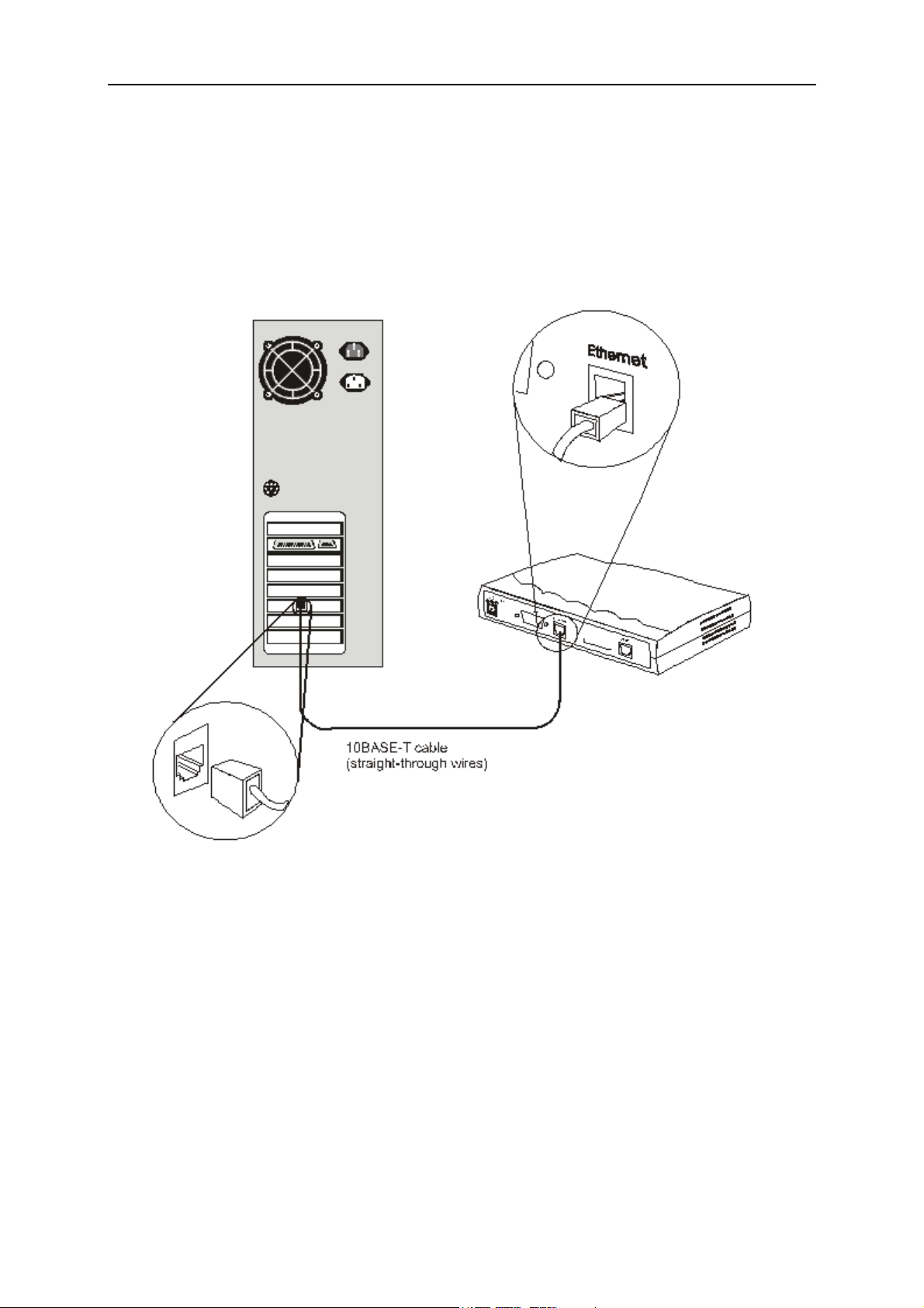
PC/Server to Modem Connection
You can connect the Modem directly to a 10BASE-T (10 Mbps) Ethernet adapter
card (NIC) installed on a PC using the Ethernet cable cable as shown in the
diagram below:
8
PC to Modem Connection
Page 13

DSL-300 ADSL Ethernet Modem User’s Guide
Software Installation
In order to install the software driver for the Modem, you first need to install the
DSL-300 Configuration Utility, D-Link’s GUI based management software. After
using it for the initial setup and configuration you can use this utility to monitor
the device or change its settings. Install the DSL-300 Configuration Utility
software on the PC directly connected to the device, or a ny PC connected to the
same Ethernet LAN as the Modem.
Install DSL-300 Configuration Utility
Install DSL-300 Configuration Utility software by inserting the setup CD-ROM
disc into your CD-ROM drive and wa it for the fol low ing screen prompts to a ppear:
1. The Setup window informs you that it is preparing the “InstallShield Wizard”.
2. The Welcome window recommends exiting all other programs before starti ng
the setup procedure. If you do not wish to close other programs click Cancel,
otherwise quit all other programs and click Next.
9
Page 14

DSL-300 ADSL Ethernet Modem User’s Guide
3. The User Information window asks you for your name and company name.
Enter this information in the appropriate field and click Next.
4. In the Choose Destination Location window you may accept to install DSL-300
Configuration Utility in the automatically chosen directory by clicking Next.
Or you can click Browse if you wish to select a different directory.
10
Page 15

DSL-300 ADSL Ethernet Modem User’s Guide
5. The Select Program F older window asks you to select a different folder or you
can rename the D-Link DSL Family folder that has been created for the
program icon. You can rename the folder by typing in a new name in the
“Program Folder:” field. Click Next to continue.
6. The Start Copying Files window provides an opportunity to review the
information you have just entered. If you are satisfied with the information as
it is listed, click Next. If you need to change any of the information click
Back to go to the previous window(s) to make the changes.
11
Page 16

DSL-300 ADSL Ethernet Modem User’s Guide
7. In the Setup Complete window you are presented with the option to launch
the DSL-300 Configuration Utility program. If you wish to start the program
now, click in the vacant box next to the “Yes, Launch the program file” option.
A check mark (√) should appear in the box indicating it has been selected.
Click Finish to launch DSL-300 Configuration Utility.
A DSL-300 Configuration Utility icon should now be seen on your desktop screen.
12
Page 17

DSL-300 ADSL Ethernet Modem User’s Guide
Configure The Modem
With the DSL-300 Configuration Utility software installed, you are ready to
configure the Modem. You must enter the VPI and VCI values that have been
given to you by your ADSL service provider to define the path of connection to
the ATM network backbone.
Click the DSL-300 Configuration Utility icon to initiate the configuration of
the Modem. The DSL-300 Configuration Utility will locate the Modem on your
LAN.
1. If the DSL-300 and corresponding MAC address does not appear in the Device
List of the DSL-300 Configuration Utility window, click the Discover button
on the bottom of the window. The DSL-300 should appear in the Device Name
column preceded by the MAC Address of the device. If there are other
DSL-300 Modems on the same network, these will also appear in the list.
2. Double-click on the Modem in the list or highlight it and depress the Enter
key.
13
Page 18

DSL-300 ADSL Ethernet Modem User’s Guide
3. In the Enter Password window, type in the password and click OK. The
default password is “admin”. You can change this password using a console
manager as described in Appendix B.
4. The main menu appears, click on the General ADSL Information tab to
configure the Modem.
14
Page 19

DSL-300 ADSL Ethernet Modem User’s Guide
5. In the new window you must enter the VPI and VCI numbers (assigned to
you by your ADSL service provider). Type in these numbers in the ADSL
Setting field and click Finish.
6. The Save configuration and restart system window will appear. You will be
asked if you would like to save the changes you have made (the VPI and VCI
numbers) and restart the Modem. Click Yes if you have correctly entered the
necessary information.
7. The final window, Configuration saved, confirms that you have made changes
to the configuration of the Modem and restarted it. If you wish to quit DSL300 Configuration Utility, click Yes.
15
Page 20

DSL-300 ADSL Ethernet Modem User’s Guide
Modem Diagnostics
The DSL-300 Configuration Utility can be used to monitor the activity and
performance of the Modem. The four status windows are read-only with the
exception of the General ADSL Information. Once you have set the VCI and VPI
values there should not be any need to change them. You can choose the interval
in which the statistics are refreshed from the pull-down menu on the bottom of
the window.
Clicking on the ADSL Status tab provides information about the status of the
ADSL link and the data. In this window you can view the following information:
♦ Link Status – current status of the ADSL link
♦ Protocol – ADSL protocol used to provide the connection
♦ Data Path – Fast or Interleave mode (depending on the DSLAM)
♦ Upstream - Displays upstream data bit rate in Kbps
♦ Downstream - Displays downstream data bit rate in Kbps
The lighted indicator indicates the connection status by its color.
♦ Red light – not connected
♦ Yellow/Black flashing light – connecting
♦ Green light - connected
16
Page 21

DSL-300 ADSL Ethernet Modem User’s Guide
The General ADSL Information menu displays information on packets received
and transmitted via the ADSL line as well as the ADSL settings. This is where
you can change the VCI and VPI va lues, as described in the previous section.
The Ethernet Information menu provides in formation about packets receiv ed and
transmitted via the Ethernet interface.
17
Page 22

DSL-300 ADSL Ethernet Modem User’s Guide
The Version Information menu lists the current device driver, firmware version
and hardware version.
Advanced Diagnostics
To view the advanced diagnostics menus available with the configuration uti tilty
depress CTRL + V while the utility is displayed.
The Advanced ADSL Information menu lists information about errors, signal
characteristics and loop distance.
18
Page 23

DSL-300 ADSL Ethernet Modem User’s Guide
The data provided in the Advanced ADSL Information window includes:
♦ Re_training – number of attempts to establish the ADSL connection
♦ CRC – Cyclic Redundancy Checking, number of CRC errors since ADSL
connection established
♦ FEC – Forward Error Correction, number of FEC errors since ADSL
connection established
♦ HEC – Header Error Checking, number of HEC errors since ADSL
connection established
♦ Line Attenuation – measured in dB
♦ Noise Margin – measured in dB
♦ Output Power – measured in dBm
The Carrier Information menu displays the frequency distribution of the
upstream and downstream bandwidth. T he upstream portion occupies the lower
frequency block.
19
Page 24

DSL-300 ADSL Ethernet Modem User’s Guide
Contacting Technical Support
D-Link provides free technical support for customers within the United States.
U.S. customers can contact D-Link technical support throug h our web site,
e-mail, or by phone.
United States technical support is available Monday through Friday from 6:00
a.m. to 6:00 p.m. (PST).
Web:
http://www.dlink.com
Email:
support@dlink.com
Phone:
949-788-0805 (option #4)
If you are a customer residing outside of the United States, please refer
to the list of D-Link locations that is included in this manual.
Thank you for purchasing this product. We like to receive feedback from our
customers concerning our products. Please take a moment to visit our web site.
You can register your purchase on-line, learn more about the newest networking
products, and let us know the things your new network has empowered you to do.
20
Page 25

Offices
AUSTRALIA D-LINK AUSTRALASIA
Unit 16, 390 Eastern Valley Way, Roseville, NSW 2069, Australia
TEL: 61-2-9417-7100 FAX: 61-2-9417-1077
TOLL FREE: 1800-177-100 (Australia), 0800-900900 (New Zealand)
URL: www.dlink.com.au
E-MAIL: support@dlink.com.au, info@dlink.com.au
CANADA D-LINK CANADA
2180 Winston Park Drive, Oakville, Ontario L6H 5W1 Canada
TEL: 1-905-829-5033 FAX: 1-905-829-5223 BBS: 1-965-279-8732
FREE CALL: 1-800-354-6522
URL: www.dlink.ca
FTP: ftp.dlinknet.com
E-MAIL: techsup@dlink.ca
CHILE D-LINK SOUTH AMERICA
Isidora Goyenechea #2934 of.702, Las Condes, Santiago, Chile
TEL: 56-2-232-3185 FAX: 56-2-2320923
URL: www.dlink.cl
E-MAIL: ccasassu@dlink.cl, tsilva@dlink.cl
DENMARK D-LINK DENMARK
Naverland 2, DK-2600 Glostrup, Copenhagen, Denmark
TEL:45-43-969040 FAX:45-43-424347
URL: www.dlink.dk
E-MAIL: info@dlink.dk
EGYPT D-LINK MIDDLE EAST
7 Assem Ebn Sabet Street, Heliopolis Cairo, Egypt
TEL: 202-2456176 FAX: 202-2456192
URL: www.dlink-me.com
E-MAIL: support@dlink-me.com, fateen@dlink-me.com
FRANCE D-LINK FRANCE
Le Florilege #2, Allee de la Fresnerie
78330 Fontenay Le Fleury France
TEL: 33-1-30238688 FAX: 33-1-3023-8689
URL: www.dlink-france.fr
E-MAIL: info@dlink-france.fr
GERMANY D-LINK CENTRAL EUROPE/D-LINK DEUSTSCHLAND GMBH
Schwalbacher Strasse 74, 65760 Eschborn Germany
TEL: 49-(0) 6196-7799-0 FAX: 49-(0) 6196-7799-300
URL: www.dlink.de
E-MAIL: mbischoff@dlink.de, mboerner@dlink.de
INDIA D-LINK INDIA
Plot No.5, Kurla-Bandra Complex Road,
Off Cst Road, Santacruz (E), Bombay - 400 098 India
TEL: 91-22-652-6696 FAX: 91-22-652-8914
URL: www.dlink-india.com
E-MAIL: service@dli nk.india.com
ITALY D-LINK ITALY
Via Nino Bonnet No. 6/b, 20154 Milano, Italy
TEL: 39-02-2900-0676
FAX: 39-02-2900-1723
E-MAIL: info@dlink.it
URL: www.dlink.it
21
Page 26

JAPAN D-LINK JAPAN
10F, 8-8-15 Nishi-Gotanda, Shinagawa-ku, Tokyo 141 Japan
TEL: 81-3-5434-9678
FAX: 81-3-5434-9868
URL: www.d-link.co.jp
E-MAIL: kida@d-link.co.jp
RUSSIA D-LINK RUSSIA
Michurinski Prospekt 49, 117607 Moscow, Russia
TEL: 7-095-737-3389, 7-095-737-3492 FAX: 7-095-737-3390
E-MAIL: vl@dlink.ru
SINGAPORE D-LINK INTERNATIONAL
1 International Business Park, #03-12 The Synergy, Singapore 609917
TEL: 65-774-6233 FAX: 65-774-6322
URL: www.dlink-intl.com
E-MAIL: info@dlink.com.sg
S. AFRICA D-LINK SOUTH AFRICA
Unit 2, Parkside 86 Oak Avenue
Highveld Technopark Centurion, Gauteng, Republic of South Africa
TEL: 27(0)126652165 FAX: 27(0)126652186
CELL NO: 0826010806 (Bertus Moller)
CELL NO: 0826060013 (Attie Pienaar)
E-MAIL: bertus@d-link.co.za, attie@d-link.co.za
SWEDEN D-LINK SWEDEN
P.O. Box 15036, S-167 15 Bromma Sweden
TEL: 46-(0)8564-61900
FAX: 46-(0)8564-61901
E-MAIL: info@dlink.se
URL: www.dlink.se
TAIWAN D-LINK TAIWAN
2F, No. 119 Pao-Chung Road, Hsin-Tien, Taipei, Taiwan
TEL: 886-2-2910-2626
FAX: 886-2-2910-1515
URL: www.dlinktw.com.tw
E-MAIL: dssqa@tsc.dlinktw.com.tw
U.K. D-LINK EUROPE
D-Link (Europe) Ltd. 4th Floor Merit House,
Edgware Road, Colindale, London NW95AB U.K.
TEL: 44-20-8731-5555 FAX: 44-20-8731-5511
URL: www.dlink.co.uk
E-MAIL: info@dlink.co.uk
U.S.A D-LINK U.S.A.
53 Discovery Drive, Irvine, CA 92618 USA
TEL: 1-949-788-0805 FAX: 1-949-753-7033
INFO LINE: 1-800-326-1688
BBS: 1-949-455-1779, 1-949-455-9616
URL: www.dlink.com
E-MAIL: tech@dlink.com, support@dlink.com
22
Page 27

Technical Specifications
General
A
Standards:
Protocol:
Data
Transfer
Rate:
Media Interface
Exchange:
DC inputs:
Power Adapter:
ITU G.992.1 (G.dmt)
ITU G.992.2 (G.lite)
ITU G.994.1 (G.Hs)
ANSI T1.413 (Issue 2)
TCP/IP
G.dmt full rate: Downstream up to 8 Mbps
Upstream up to 640 Kbps
G.lite: Downstream up to 1.5 Mbps
Upstream up to 512 Kbps
RJ-11 port ADSL telephone line connection
RJ-45 port for 10BASET Ethernet connection
Physical and Environmental
Input: 120V AC 60Hz 24W
Output: 12V DC 1000 mA
Power
Consumptio
n:
Operating
Temperatur
e:
Humidity:
Dimensions
:
Weight:
EMI:
Safety:
10 Watts (Max)
0° to 50° C (32° - 122° F)
5 to 95% (non-condensing)
223.3mm x 131.7mm x 35mm
455gm (1 lb.)
CE Class B FCC Class B C-Tick BSMI
UL/CUL TUV
23
Page 28

B
Creating a New Password
You should change the access password for the DSL-300 Configuration Utility
program when you first setup the device. In order to change the password you
will need a console program such as Microsoft HyperTeminal installed on your
PC and an RS-232 cable.
The HyperTerminal program is included with Windows operating systems. If i t is
not available see the instructions for installing HyperTerminal from the
Windows installation program. Once it is installed, you can access
HyperTerminal from the Start menu. To access HyperTerminal, choose
Accessories, then select the Communications file, open the HyperTerminal file,
double-click on the HYPERTERMINAL.EXE file and follow the instructions from
the prompts.
Once you have the active HyperTerminal screen in view on your desktop, hit the
Enter key. The Internet Protocol (IP) address of the DSL-300 will be displayed.
The cursor in the terminal screen should be blinking immediately to the right of
the IP address. Type in diap passwd followed by a space and the new
password, and hit the Enter key. For example, if you want to create a new
password such as “Open”, you would type diap passwd Open and the new
password is now “Open”. This will be confirmed by a message on the terminal
screen stating that the new password is Open. The password is case sensitive, so
enter it exactly how you would like the password to be entered.
When you have entered the new password and received confirmation you must
save it for the change to go into effect. To save the new password type config
save and hit the Enter key. A message will inform you that the configuration
is being saved followed by a confirmation that the configuration has been saved.
When you have successfully changed and saved the password you can end the
session by simply closing the HyperTerminal window or by typing exit and
closing the window.
24
Page 29
C
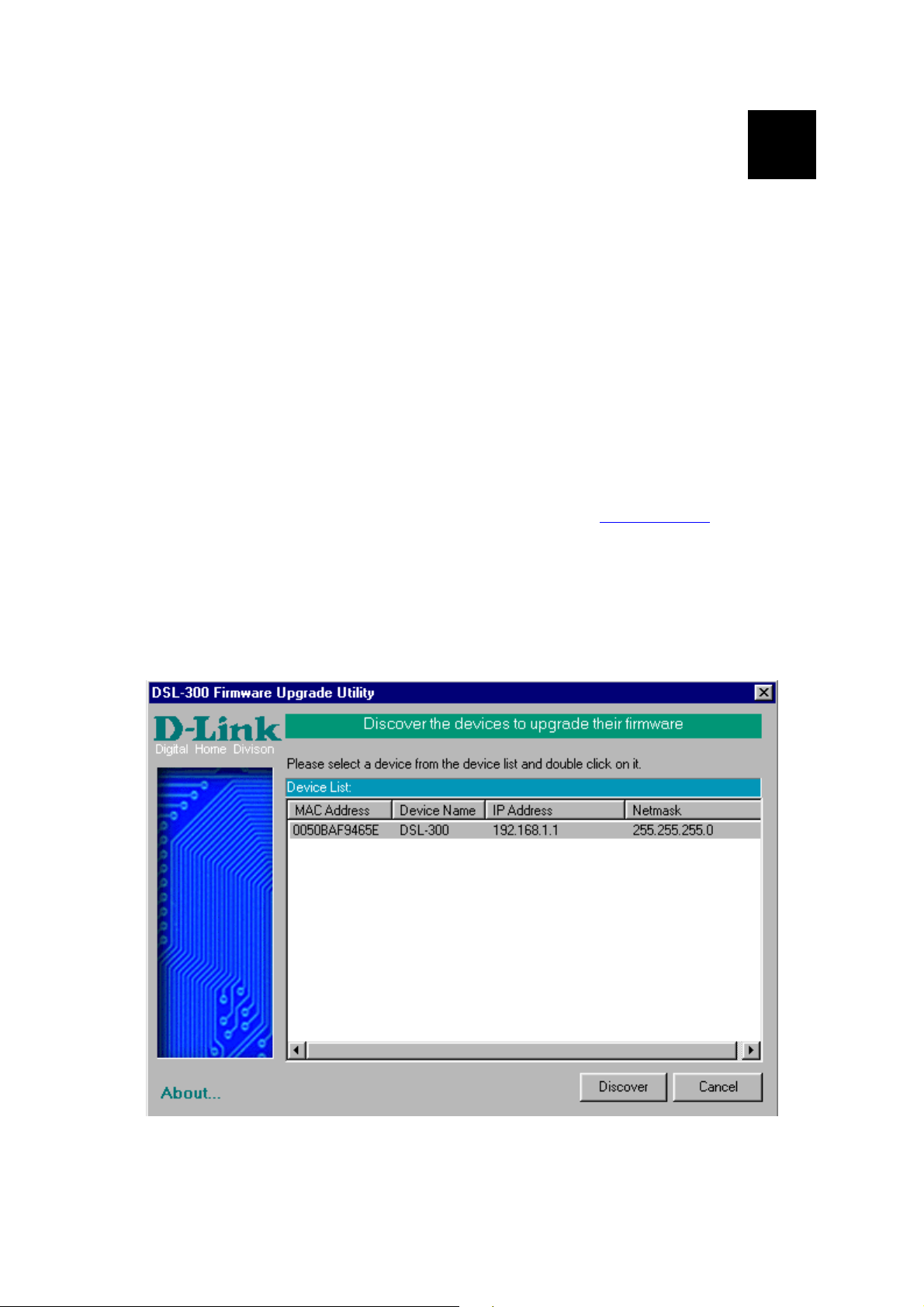
DSL-300 Firmware Upgrade Utility
You can update system firmware using the DSL-300 Firmware Upgrade Utility.
To upgrade the Router’s firmware you must have installed this software on the
PC you wish to use for this purpose. Install the utility by clicking the selfexecuting file setup.exe located on the Installation CD-ROM. It will be installed
automatically. It is recommended that the PC be directly connected to the Router
using a crossed cable, however you may upgrade it through the LAN from a
remote host.
You also need to download the latest firmware version file from the D-Link web
site to the PC on which you will use the Upgrade Utility. Instructions for
downloading the firmware are located on the web site at www.dlink.com.
To launch the DSL-300 Firmware Upgrade Utility, click on the icon. Allow a few
moments for the software to discover the Router on the network. After the
discovery phase the following window will appear. You will see all the DSL-300
Routers on your network. You can identify individual devices by either its IP
address or its MAC address. Select the device you wish to upgrade by double
clicking on it.
25
Page 30

When you select a Router to upgrade you will be prompted for a password. The
default password is Admin. If you want to change the password, you can change
it using the console manager interface as described in Appendix B.
Enter the password and click OK.
In the new window you will see the MAC address of the Router and the IP
address of the PC you are using. The PC and the Router must be on the same
subnet for the upgrade to be completed. The upgrade utility will suggest a new IP
address to be temporarily assigned to the device during the firmware upgrade
procedure. Check the suggested IP address listed for the Router to be sure that it
does not conflict with any existing IP addresses on your network. To change the
temporary IP address of the Router, type in an available IP address in the space
provided. You should change only the host portion of the address.
To upload the new firmware to the selected Router click the ‘Upgrade’ button.
The utility will automatically load the new firmware. During the upgrade process
it is important that you allow the entire file to load onto the device. Do not turn
off the Router while the flash memory is being updated. A warning will appear
during the upgrade reminding you not to power off the device.
26
Page 31

When the new firmware has been successfully loaded a new window will inform
you of the upgrade and tell you that the Router has been restarted. Click OK to
proceed.
27
Page 32

Wichtige Sicherheitshinweise
1. Bitte lesen Sie sich diese Hinweise sorgfältig durch.
2. Heben Sie diese Anleitung für den spätern Gebrauch auf.
3. Vor jedem Reinigen ist das Gerät vom Stromnetz zu trennen. Vervenden Sie keine Flüssig- oder
Aerosolreiniger. Am besten dient ein angefeuchtetes Tuch zur Reinigung.
4. Um eine Beschädigung des Gerätes zu vermeiden sollten Sie nur Zubehörteile verwenden, die vom
Hersteller zugelassen sind.
5. Das Gerät is vor Feuchtigkeit zu schützen.
6. Bei der Aufstellung des Gerätes ist auf sichern Stand zu achten. Ein Kippen oder Fallen könnte
Verletzungen hervorrufen. Verwenden Sie nur sichere Standorte und beachten Sie die Aufstellhinweise
des Herstellers.
7. Die Belüftungsöffnungen dienen zur Luftzirkulation die das Gerät vor Überhitzung schützt. Sorgen Sie
dafür, daß diese Öffnungen nicht abgedeckt werden.
8. Beachten Sie beim Anschluß an das Stromnetz die Anschlußwerte.
9. Die Netzanschlußsteckdose muß aus Gründen der elektrischen Sicherheit einen Schutzleiterkontakt
haben.
10. Verlegen Sie die Netzanschlußleitung so, daß niemand darüber fallen kann. Es sollete auch nichts auf
der Leitung abgestellt werden.
11. Alle Hinweise und Warnungen die sich am Geräten befinden sind zu beachten.
12. Wird das Gerät über einen längeren Zeitraum nicht benutzt, sollten Sie es vom Stromnetz trennen.
Somit wird im Falle einer Überspannung eine Beschädigung vermieden.
13. Durch die Lüftungsöffnungen dürfen niemals Gegenstände oder Flüssigkeiten in das Gerät gelangen.
Dies könnte einen Brand bzw. Elektrischen Schlag auslösen.
14. Öffnen Sie niemals das Gerät. Das Gerät darf aus Gründen der elektrischen Sicherheit nur von
authorisiertem Servicepersonal geöffnet werden.
15. Wenn folgende Situationen auftreten ist das Gerät vom Stromnetz zu trennen und von einer
qualifizierten Servicestelle zu überprüfen:
a – Netzkabel oder Netzstecker sint beschädigt.
b – Flüssigkeit ist in das Gerät eingedrungen.
c – Das Gerät war Feuchtigkeit ausgesetzt.
d – Wenn das Gerät nicht der Bedienungsanleitung ensprechend funktioniert oder Sie mit Hilfe dieser
Anleitung keine Verbesserung erzielen.
e – Das Gerät ist gefallen und/oder das Gehäuse ist beschädigt.
f – Wenn das Gerät deutliche Anzeichen eines Defektes aufweist.
16. Bei Reparaturen dürfen nur Orginalersatzteile bzw. den Orginalteilen entsprechende Teile verwendet
werden. Der Einsatz von ungeeigneten Ersatzteilen kann eine weitere Beschädigung hervorrufen.
17. Wenden Sie sich mi t allen Fragen die Service u nd Repartur betreffen an Ihren Servicepartner. Somit
stellen Sie die Betriebssicherheit des Gerätes sicher.
18. Zum Netzanschluß dieses Gerätes ist eine geprüfte Leitung zu verwenden, Für einen Nennstrom bis 6A
und einem Gerätegewicht großer 3kg ist eine Leitung nicht leichter als H05VV-F, 3G, 0.75mm2
einzusetzen
Limited Warranty
Hardware:
D-LINK WARRANTS EACH OF ITS HARDWARE PRODUCTS TO BE F REE FROM DEFECTS IN WORKMANSHIP
AND MATERIALS UNDER NORMAL USE AND SERVICE FOR A PERIOD COMMENCING ON THE DATE OF
PURCHASE FROM D-LINK OR ITS AUTHORIZED RESELLER AND EXTENDING FOR THE LENGTH OF TIME
STIPULATED BY THE AUTHORIZED RESELLER OR D-LINK BRANCH OFFICE NEAREST TO THE PLACE OF
PURCHASE.
THIS WARRANTY APPLIES ON THE CONDITION THAT THE PRODUCT REGISTRATION CARD IS FILLED OUT
AND RETURNED TO A D-LINK OFFICE WITHIN NINETY (90) DAYS OF PURCHASE. A L IST OF D-L INK OF FICES
IS PROVIDED AT THE BACK OF THIS MANUAL , TOGETHER WITH A COPY OF THE REGISTRATION CARD.
IF THE PRODUCT PROVES DEFECTIVE WITHIN THE APPLICABLE WARRANTY PERIOD, D-LINK WILL
PROVIDE REPAIR OR REPLACEMENT OF THE PRODUCT. D-LINK SHALL HAVE THE SOLE DISCRETION
WHETHER TO REPAIR OR REPLACE, AND REPLACEMENT PRODUCT MAY BE NEW OR RECONDITIONED.
REPLACEMENT PRODUCT SHALL BE OF EQUIVALENT OR BETTER SPECIFICATIONS, RELATIVE TO THE
28
Page 33

DEFECTIVE PRODUCT, BUT NEED NOT BE IDENTICAL. ANY PRODUCT OR PART REPAIRED BY D-LINK
PURSUANT TO THIS WARRANT Y SHALL HAVE A WARRANTY PERIOD OF NOT LESS THAN 90 DAYS, FROM
DATE OF SUCH REPAIR, IRRESPECTIVE OF AN Y EARLIER EXPIRATION OF ORIGINAL WARRANTY PERIOD.
WHEN D-LINK PROVIDES REPLACEMENT , THEN THE DEFECTIVE PRODUCT BECOMES T HE PROPERTY OF
D-LINK.
WARRANTY SERVICE MAY BE OBTAINED BY CONTACTING A D-LINK OFFICE WITHIN THE APPLICABLE
WARRANTY PERIOD, AND REQUESTING A RETURN MATERIAL AUTHORIZATION (RMA) NUMBER. IF A
REGISTRATION CARD FOR THE PRODUCT IN QUESTION HAS NOT BEEN RETURNED TO D-LINK, THEN A
PROOF OF PURCHASE (SUCH AS A COPY OF THE DATED PURCHASE INVOICE) MUST BE PROVIDED. IF
PURCHASER'S CIRCUMSTANCES REQUIRE SP ECIAL HANDL ING OF W ARRANTY CORRECTION , THEN AT THE
TIME OF REQUESTING RMA NUMBER, P URCHASER MAY ALSO PROPOSE SPECIAL PROCEDURE AS MAY BE
SUITABLE TO THE CASE.
AFTER AN RMA NUMBER IS ISSUED, THE DEFECTIVE P RODUCT MUST BE PACKAGED SECURELY IN THE
ORIGINAL OR OTHER SUITABLE SHIPPING PACKAGE TO ENSURE THAT IT WILL NOT BE DAMAGED IN
TRANSIT, AND THE RMA NUMBER MUST BE PROMINENTL Y MARKED ON THE OUTSIDE OF THE PACKAGE.
THE PACKAGE MUST BE MAILED OR OTHERWISE SHIPPED TO D-LINK WITH ALL COSTS OF
MAILING/SHIPPING/INSURANCE PREPAID. D-LINK SHALL NEVER BE RESPONSIBLE FOR ANY SOFTWARE,
FIRMWARE, INFORMATION, OR MEMORY DATA OF PURCHASER CONTAINED IN, STORED ON, OR
INTEGRATED WITH ANY PRODUCT RETURNED TO D-LINK PURSUANT TO THIS WARRANTY.
ANY PACKAGE RETURNED TO D-LINK W ITHOUT AN RMA NUMBER W ILL BE REJECTED AN D SHIP PED BACK
TO PURCHASER AT PURCHASER' S EXPENSE, AND D-LIN K RESERVES THE RIGHT IN SUCH A CASE TO LEVY
A REASONABLE HANDLING CHARGE IN ADDIT ION MAILING OR SHIPPING COSTS.
Software:
WARRANTY SERVICE FOR SOFTWARE PRODUCTS MAY BE OBTAINED BY CONTACTING A D-LINK OFFICE
WITHIN THE APPLICABL E WARRANTY PERIOD. A LIST OF D-LINK OFFICES IS PROVIDED AT THE BACK OF
THIS MANUAL, TOGETHER W ITH A COPY OF THE REGISTRATION CARD. IF A REGISTRAT ION CARD FOR THE
PRODUCT IN QUESTION HAS NOT BEEN RETURN ED TO A D-LINK OFFICE, THEN A PROOF OF PURCHASE
(SUCH AS A COPY OF THE DATED PURCHASE INVOICE) MUST BE PROVIDED WHEN REQUESTING
WARRANTY SERVICE. THE TERM "PU RCHASE" IN THIS SOF TWARE WARRANTY REF ERS TO THE PU RCHASE
TRANSACTION AND RESULTING LICENSE TO USE SUCH SOFTWARE.
D-LINK WARRANTS THAT ITS SOFTWARE PRODUCTS WILL PERFORM IN SUBSTANTIAL CONFORMANCE
WITH THE APPLICABLE PRODUCT DOCUMENTATION PROVIDED BY D-LINK WITH SUCH SOFTWARE
PRODUCT, FOR A PERIOD OF NINETY (90) DAYS FROM THE DATE OF PURCHASE FROM D-LINK OR ITS
AUTHORIZED RESELLER. D-LINK WARRANTS THE MAGNETIC MEDIA, ON WHICH D-LINK PROVIDES ITS
SOFTWARE PRODUCT, AGAINST FAILURE DURING THE SAME WARRANTY PERIOD. THIS WARRANTY
APPLIES TO PURCHASED SOFTWARE, AND TO REPLACEMENT SOFTWARE PROVIDED BY D-LINK PURSUANT
TO THIS WARRANTY, BUT SHALL NOT APPLY TO ANY UPDATE OR REPLACEMENT WHICH MAY BE
PROVIDED FOR DOWNLOAD VIA THE INTERNET, OR TO ANY UPDATE WHICH MAY OTHERWISE BE
PROVIDED FREE OF CHARGE.
D-LINK'S SOLE OBLIGATION UN DER THIS SOFTWARE WARRANT Y SHALL BE TO REPLACE ANY DEF ECTIVE
SOFTWARE PRODUCT WITH PRODUCT WHICH SUBSTANTIALLY CONFORMS TO D-LINK'S APPLICABLE
PRODUCT DOCUMENTATION. PURCHASER ASSUMES RESPONSIBILITY FOR THE SELECTION OF
APPROPRIATE APPLICATION AND SYSTEM/PLATFORM SOFTWARE AND ASSOCIATED REFERENCE
MATERIALS. D-LINK MAKES NO WARRANTY THAT ITS SOFTWARE PRODUCTS WILL WORK IN
COMBINATION WITH ANY HARDWARE, OR ANY APPL ICATION OR SYSTEM/ PLATF ORM SOFT WARE P RODUCT
PROVIDED BY ANY THIRD PARTY, EXCEPTIN G ONLY SUCH PRODUCTS AS ARE EXPRESSLY REPRESENTED,
IN D-LINK'S APPLICABLE PRODUCT DOCUMENTATION AS BEING COMPATIBLE. D-LINK'S OBLIGATION
UNDER THIS WARRANTY SHALL BE A REASONABLE EFFORT TO PROVIDE COMPATIBILITY, BUT D-LINK
SHALL HAVE NO OBLIGATION TO PROVIDE COMP ATIBILITY WHEN THERE IS FAU LT IN THE THIRD-PART Y
HARDWARE OR SOFTWARE. D-LINK MAKES NO WARRANTY THAT OPERATION OF ITS SOFTWARE
PRODUCTS WILL BE UNINTERRUPTED OR ABSOLUTELY ERROR-FREE, AND NO WARRANTY THAT ALL
DEFECTS IN THE SOFTWARE PRODUCT, WITHIN OR WITHOUT THE SCOPE OF D-LINK'S APPLICABLE
PRODUCT DOCUMENTATION, W IL L BE CORRECTED.
LIMITATION OF WARRANTIES
IF THE D-LINK PRODUCT DOES NOT OPERATE AS WARRANTED ABOVE, THE CUST OMER'S SOLE REMEDY
29
Page 34

SHALL BE, AT D-LINK'S OPTION, REPAIR OR REPLACEMENT. THE FOREGOING WARRANTIES AND
REMEDIES ARE EXCLUSIVE AND ARE IN LIEU OF ALL OTHER WARRANTIES, EXPRESSED OR IMPLIED,
EITHER IN FACT OR BY OPERATION OF LAW, STATUTORY OR OTHERWISE, IN CLUDING WARRANTIES OF
MERCHANTABILITY AND FITNESS FOR A PARTICULAR PURPOSE. D-LINK NEITHER ASSUMES NOR
AUTHORIZES ANY OTHER PERSON TO ASSUME F OR IT ANY OTHER LIABILITY IN CONN ECTION WITH THE
SALE, INSTALLATION MAINT EN ANCE OR USE OF D-LINK'S PRODUCTS
D-LINK SHALL NOT BE LIABLE UNDER THIS WARRANTY IF ITS TESTING AND EXAMINATION DISCLOSE
THAT THE ALLEGED DEFECT IN THE PRODUCT DOES NOT EXIST OR WAS CAUSED BY T HE CUSTOMER' S OR
ANY THIRD PERSON'S MISUSE, NEGLECT, IMPROPER INSTALLATION OR TESTING, UNAUTHORIZED
ATTEMPTS TO REPAIR, OR ANY OTHER CAUSE BEYOND THE RANGE OF THE INTENDED USE, OR BY
ACCIDENT, FIRE, LIGHTNING OR OT HER HAZARD.
LIMITATION OF LIABILITY
IN NO EVENT WILL D-LINK BE LIABLE FOR ANY DAMAGES, INCL UDING LOSS OF DATA, LOSS OF PROFITS,
COST OF COVER OR OTHER INCIDENTAL, CONSEQUENTIAL OR INDIRECT DAMAGES ARISING OUT THE
INSTALLATION, MAINT ENANCE, USE, PERFORMANCE, FAILU RE OR IN TERRUPTION OF A D- LINK PRODUCT,
HOWEVER CAUSED AND ON ANY THEORY OF LIABILITY. THIS LIMITATION WILL APPLY EVEN IF D-LINK
HAS BEEN ADVISED OF THE POSSIBILITY OF SUCH DAMAGE.
IF YOU PURCHASED A D-LINK PRODUCT IN THE UNITED STATES, SOME STATES DO NOT ALLOW THE
LIMITATION OR EXCLUSION OF LIABILITY FOR INCIDENTAL OR CONSEQUENTIAL DAMAGES, SO THE
ABOVE LIMITATION MAY NOT APPLY TO YOU.
Trademarks
Copyright 2000 D-Link Corporation.
Contents subject to change without prior notice.
D-Link is a registered trademark of D-Link Corporation/D-Link Systems, Inc.
All other trademarks belong to their respective proprietors.
Copyright Statement
No part of this publication may be reproduced in any form or by any means or
used to make any derivative such as translation, transformation, or adaptation
without permission from D-Link Corporation/D-Link Systems Inc., as stipulated
by the United States Copyright Act of 1976
30
Page 35

FCC Warning
This device complies with part 15 of the FCC Rules. Operation is subject to the following
two conditions: (1) This device may not cause harmful interference, and (2) this device
must accept any interference received, including interference that may cause undesired
operation.
This equipment has been tested and found to comply with the limits for a Class B digital
device, pursuant to part 15 of the FCC Rules. These limits are designed to provide
reasonable protection against harmful interference in a residential installation. This
generates, uses and can radiate radio frequency energy and, if not installed and used in
accordance with the instructions, may cause harmful interference to radio
communications. However, there is no guarantee that interference will not occur in a
particular installation. If this equipment does cause harmful interference to radio or
television reception, which can be determined by turning equipment off and on, the user
is encouraged to try to correct the interference by one or more of the following measures:
-Reorient or relocate the receiving antenna.
-Increase the separation between the equipment and receiver.
-Connect the equipment into an outlet on a circuit different from that to which the
receiver is connected.
-Consult the dealer or an experienced radio/TV technician for help.
CE Mark Warning
This is a Class B product. In a domestic environment, this product may cause radio
interference in which case the user may be required to take adequate measures.
VCCI Class B Warning
31
 Loading...