

Page 1
D-Link DSL-2760U USER’S MANUAL
1
Page 2

D-Link DSL-2760U USER’S MANUAL
2
Table of Contents
TABLE OF CONTENTS ................................................................................. 2
ABOUT THIS USER’S GUIDE ....................................................................... 4
INTRODUCTION ........................................................................................... 4
PACKAGE CONTENTS ................................................................................. 5
SYSTEM REQUIREMENTS ........................................................................... 5
FEATURES AND BENEFITS ......................................................................... 6
HARDWARE OVERVIEW .............................................................................. 7
RONT VIEW ................................................................................................ 7
F
R
EAR VIEW (CONNECTIONS) ......................................................................... 8
INSTALLATION ............................................................................................. 9
EFORE YOU BEGIN ..................................................................................... 9
B
I
NSTALLATION NOTES ................................................................................... 9
I
NFORMAT ION YOU WILL NEED FROM YOUR ADSL SERVICE PROVIDER ............ 11
I
NFORMAT ION YOU WILL NEED ABOUT DSL-2760U ....................................... 12
I
NFORMAT ION YOU WILL NEED ABOUT YOUR LAN OR COMPUTER.................... 13
DEVICE INSTALLATIO N ............................................................................. 14
OWER ON ROUTER ................................................................................... 14
P
F
ACTORY RESET BUTTON ........................................................................... 14
N
ETWORK CONNECTIONS ........................................................................... 15
WEB USER INTERFACE ............................................................................ 16
DEVICE INFO .............................................................................................. 17
UMMARY ................................................................................................. 18
S
WAN......................................................................................................... 19
S
TATISTICS ................................................................................................ 20
R
OUTE ...................................................................................................... 22
ARP ......................................................................................................... 22
DHCP ....................................................................................................... 23
ADVANCED SETUP .................................................................................... 24
L
AYER2 INTERFACE .................................................................................... 25
W
IDE AREA NETWORK (WAN) SERVICE ....................................................... 27
LAN .......................................................................................................... 47
NAT
– VIRTUAL SERVERS ........................................................................... 49
NAT
– PORT TRIGGERING ........................................................................... 51
NAT
– DMZ HOST ..................................................................................... 53
NAT
– ALG ............................................................................................... 53
S
ECURITY – IP FILTERING ........................................................................... 54
S
ECURITY – MAC FILTERING ....................................................................... 57
P
ARENTAL CONTROL – TIME RESTRICTION ................................................... 59
P
ARENTAL CONTROL – URL FILTER ............................................................. 60
Q
UALITY OF SERVICE (QOS) ....................................................................... 61
R
OUTING ................................................................................................... 64
D
OMAIN NAME SERVER (DNS) CONFIGURATION .......................................... 66
D
YNAMIC DNS CONFIGURATION ................................................................. 67
DSL
SETTINGS .......................................................................................... 69
U
NIVERSAL PLUG AND PLAY (UPNP) CONFIGURATION .................................. 72
P
RINT SERVER SETTINGS ........................................................................... 72
S
AMBA USB STORAGE ............................................................................... 73
PPTP ....................................................................................................... 74
I
NTERFACE GROUPING ............................................................................... 75
LAN
PORTS CONFIGURATION ..................................................................... 77
WIRELESS .................................................................................................. 78
ASIC WIRELESS CONFIGURATION .............................................................. 79
B
SECURITY .................................................................................................. 80
MAC
FILTER .............................................................................................. 86
Page 3

D-Link DSL-2760U USER’S MANUAL
3
WIRELESS BRIDGE ..................................................................................... 88
A
DVANCED ................................................................................................ 90
S
TATION INFO ............................................................................................ 91
DIAGNOSTICS ............................................................................................ 92
THERNET CONNECTION TEST ................................................................... 93
E
USB
CONNECTION TEST ............................................................................ 93
W
IRELESS CONNECTION TEST .................................................................... 94
ADSL
SYNCHRONIZATION TEST .................................................................. 94
ATM
OAM SEGMENT PING TEST ................................................................ 95
ATM
OAM END-TO-END PING TEST ............................................................ 96
MANAGEMENT ........................................................................................... 97
ETTINGS .................................................................................................. 98
S
S
YSTEM LOG ............................................................................................. 99
SNMP
TR-069
I
A
U
R
AGENT ......................................................................................... 100
CLIENT ....................................................................................... 101
NTERNET TIME ........................................................................................ 102
CCESS CONTROL ................................................................................... 103
PDATE SOFTWARE ................................................................................. 104
EBOOT .................................................................................................. 105
ADD A NETWORK P RINTER IN WINDOWS XP ....................................... 106
TROUBLESHOOTING ............................................................................... 115
OW DO I CONFIGURE MY DSL-2760U ROUTER WITHOUT THE CD-ROM? .. 115
H
H
OW DO I RESET MY ROUTER TO THE FACT ORY DEFAULT SETTINGS? ........... 115
W
HAT CAN I DO IF MY ROUTER IS NOT WORKING CORRECTLY? .................... 116
W
HY CAN’T I GET AN INTERNET CONNECTION? ........................................... 116
W
HAT CAN I DO IF MY ROUTER CAN’T BE DETECTED BY RUNNING THE
INSTALLATION
CD? ................................................................................... 117
KNOWLEDGE BASE ................................................................................ 118
HECK YOUR IP ADDRESS ....................................................................... 118
C
S
T A TICALLY ASSIGN AN IP ADDRESS .......................................................... 119
TECHNICAL SPECIFICAT IONS ................................................................ 120
D-LINK WORLDWIDE OFFICES ............................................................... 122
WARRANTY .............................................................................................. 123
REGISTRATION ........................................................................................ 128
Page 4

D-Link DSL-2760U USER’S MANUAL
4
About this User’s Guide
This user’s guide provides a wonderful insight into the functionality of the product called the DSL-2760U. This guide is based on the current running
firmware/software version available for this product and might touch on some new and exciting t opics never seen on this product line before providing a
rewarding reading experience and in the end acts as a guide when installing and maintaining this product.
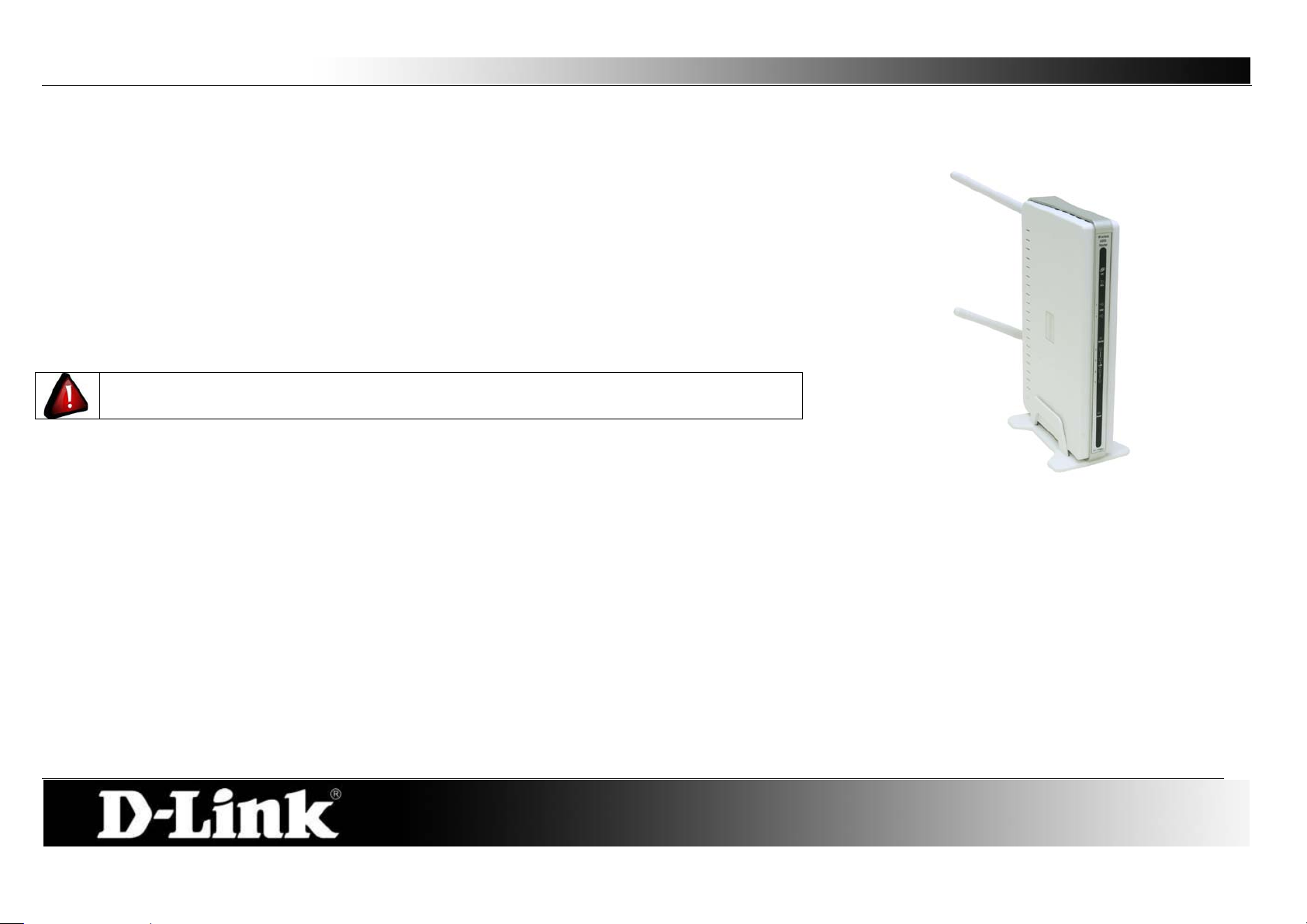
Introduction
ULTIMATE I NTERN ET CONNECTION
The DSL-2760U router is a versatile, high-performance remote router for home and the small office. With integrated ADSL2/2+ supporting up to 24Mbps
download speed, firewall protection, Quality of Service (QoS), draft 802.11n wireless LAN and 4 Ethernet switch ports, this router provides all the functions that a
home or small office needs to establish a secure and high-speed remote link to the outside world.
ULTIMATE WIRELESS CONNECTION WITH MAXIMAL SECURITY
Powered by RangeBooster N technology, this router provides wireless speeds that are up to 4 times faster than 802.11g. Maximize wireless performance by
connecting this router to computers equipped with RangeBooster N w ireless interfaces and s tay connected from virtually anyw here at home and in the of fice. The
router can also be used with 802.11g and 802.11b w ireless networks to enabl e significantly improved reception. It support s WPA/WP A2 and WEP for flexible user
access security and data encryption methods.
FIREWALL PROTECTION & QoS
Security features prevents unauthorized access to the home and off ice network, be it from the wireless devices or from the internet. The router provides firewall
security using Stat eful Packet Inspection (SPI) and hacker attack logging for Denial of Service (DoS) attack protection. SPI inspects the contents of all incoming
packet headers before deciding what packets are allowed to pass through. Router access control is provided with packet filtering based on port and
source/destination MAC/IP addresses. For Quality of Service (QoS), the router supports m ultiple priorit y queues to enable a group of home or office users to
experience the benefit of smooth network connection of inbound and outbound data without concern of traffic congestion. This QoS support allows users to enjoy
high ADSL transmission for applications such as VoIP and streaming multimedia over the Internet.
Page 5
D-Link DSL-2760U USER’S MANUAL
5
One DSL-2760U Wireless N ADSL2+ Modem Router
One Quick Installation Guide
Package Contents
Open the shipping carton and carefully remove all items. In addition to this Manual, asc ertain that you have:
One External Power Adapter
One CD-ROM with User Manual
One Twisted-pair telephone cable used for ADSL connection
One Straight-through Ethernet cable
If any of the packaging content is damaged or missing, please contact your dealer immediately.
Also keep the box and packaging materials in case you need to ship the unit in the future.
CAUTION: If powering up the router with DC power , the router must be used with the power
adapter included with the device.
System Requirements
Please note that the following requirements are the bare minimum requirements needed to successfully use this router:
1. ADSL Internet connection service normally provided by an Internet Service Provider (ISP).
2. Computer with: CPU Processor 200MHz or above, Memory (RAM) 64MB or above, CD-ROM Drive.
3. Ethernet Adapter with TCP/IP Protocol Installed.
4. Internet Browser for the setup. (Internet Explorer v6 or later, Firefox v1.5, or Safari 1.3 or above )
5. Operating System (Microsoft Windows 2000/XP/Vista )
6. D-Link Click'n Connect Utility
Page 6

D-Link DSL-2760U USER’S MANUAL
6
Features and Benefits
PPP (Point-to-Point Protocol) Security – The Router supports PAP (Password Authentication Protocol) and CHAP (Challeng e Handshake
Authentication Protocol) for PPP connections. The Router also supports MSCHAP.
DHCP Support – Dynamic Host Configuration Protocol automatically and dynamically assigns all LAN IP settings to each host on your network. This
eliminates the need to reconfigure every host whenever changes in network topology occur.
Network Address Translation (NAT) – For small office environments, the Router allows multiple users on the LAN to access the Internet
concurrently through a single Internet account. This provides Internet access to everyone in the office for the price of a single user. NAT improves
network security in effect by hiding the private network behind one global and visible IP address. NAT address mapping can also be used to link two IP
domains via a LAN-to-LAN connection.
TCP/IP (Transfer Control Pro tocol/Internet Protocol) – The Router supports TCP/IP protocol, the language used for the Internet. It is
compatible with access servers manufactured by major vendors.
RIP-1/RIP-2 – The Router supports both RIP-1 and RIP-2 exchanges with other routers. Using both versions lets the Router to communicate with all
RIP enabled devices.
Static Routing – This al lows you to select a da ta path to a p a rticular networ k destination that w ill remain in the routing t able and never “age out”. If you
wish to define a specific route that will always be used for data tr affic from your LAN to a specific destination within your LAN (for example to another
router or a server) or outside your network (to an ISP defined default gateway for instance).
Default Routing – This allows you to choose a default path for incoming data packets for which the destination address is unknown. This is
particularly useful when/if the Router functions as the sole connection to the Internet.
ATM (Asynchronous Transfer Mode) – The Router supports Bridged Ethernet over ATM (RFC1483), IP over ATM (RFC1577), and PPP over ATM
(RFC 2364).
Precise ATM Traffic Shaping – Traf fic shaping is a method of cont rolling the flow rate of ATM data cells. This function helps to establish the Quality o f
Service for ATM data transfer.
High Performance – Very high rates of data transfer are possible with the Router. Up to 24 Mbps downstream bit rate using ADSL 2+ standard.
Full Network Management – The Router incorporates SNMP (Simple Network Management Protocol) support for web-based management and
text-based network management via an RS-232 or Telnet connection.
Telnet Connection – The Telnet enables a network manager to access the Router’s management software remotely.
Easy Installation – The Router uses a web-based graphical user interface program for convenient management access and easy set up. Any
common web browser software can be used to manage the Router.
Page 7
D-Link DSL-2760U USER’S MANUAL
7
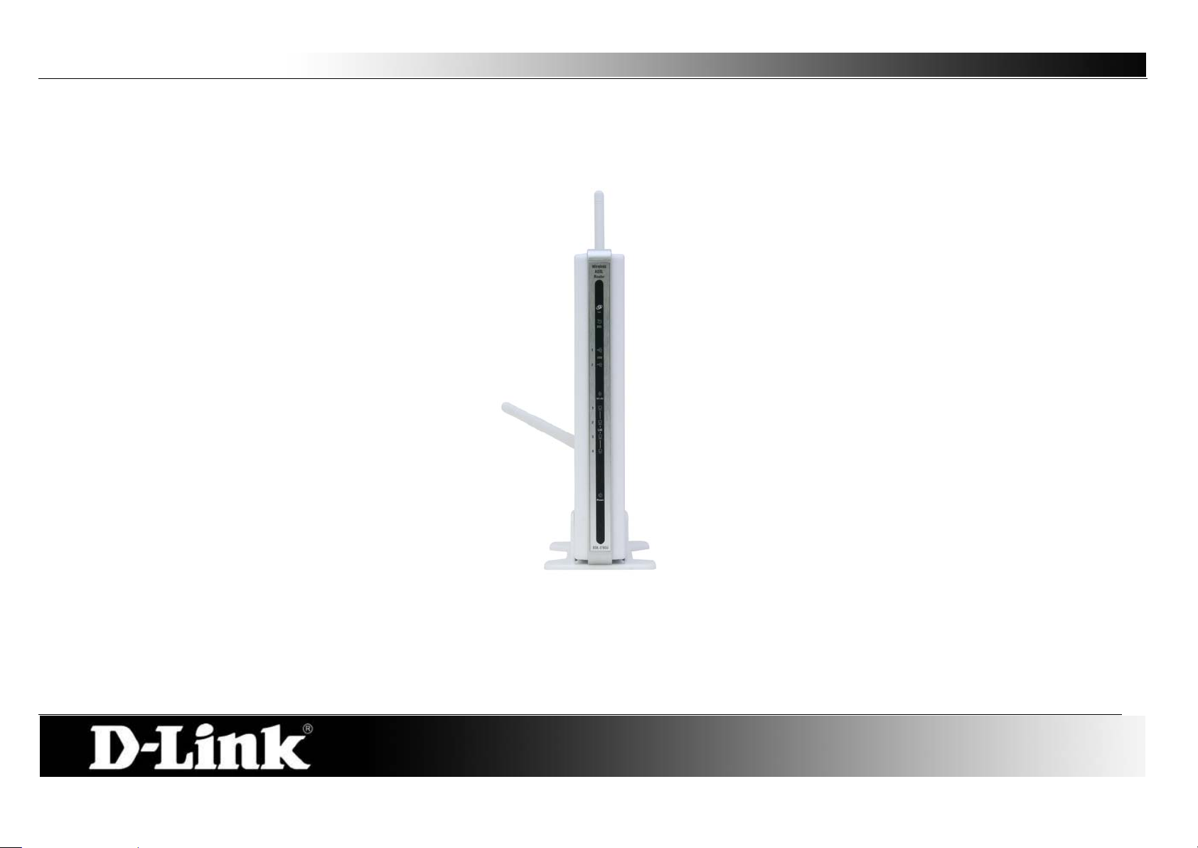
Power Light:
This light will be solid green indicating that the unit is powered on.
LAN (1-4) Lights:
This light (if active) will be blinking in green indicating that there is network activity.
WLAN Light:
This light (if enabled) will be blinking in green indicating that there is network activity.
DSL Light:
This light will be solid green when the ADSL line has successfully synchronized.
Internet Light:
This light will be solid green when the Internet dialup has authenticated successfully.
Hardware Overview
Front View
Page 8
D-Link DSL-2760U USER’S MANUAL
8
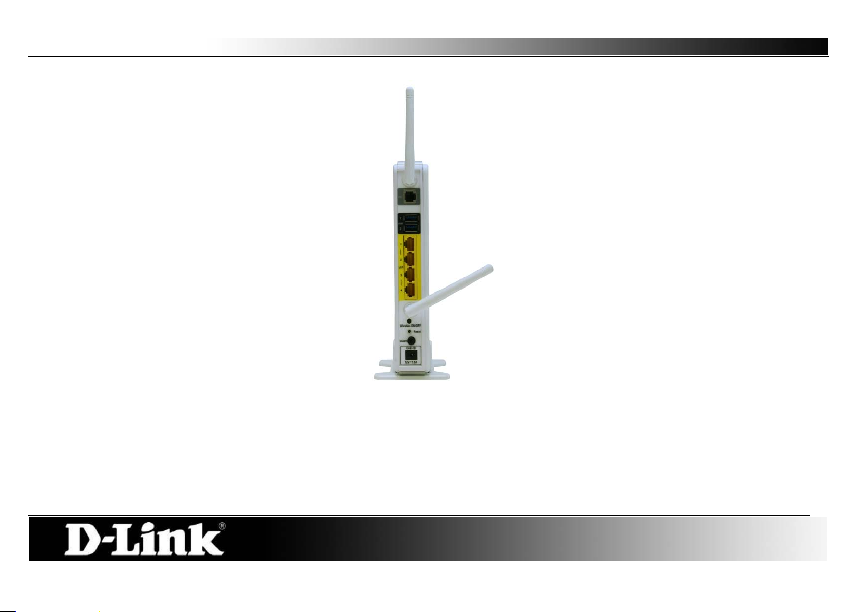
DSL Port:
This is an RJ-11 ADSL line port that connects t he router to the ADSL line.
USB Ports:
The USB ports are for USB storage devices and/or USB printers.
LAN (1-4) Ports:
These are Fast Ethernet LAN Ports that connects this router to the local network using CAT5 cables.
WLAN Button:
Press the button to turn Wireless LAN on or off.
Reset Button:
Press this button and hold it for 6 seconds to revert the Router back to factory defaults.
Power Button:
Press the button to turn the power on or off.
Power Receptacle:
The supplied power adapter connects here.
Rear View (Connections)
Page 9

D-Link DSL-2760U USER’S MANUAL
9
Installation
This section will walk you through the installation process. Placement of the Router is very important. Do not place the Router in an enclosed area such as a
closet, cabinet, or in the attic or garage.
Before You Begin
Please read and make sure you understand all the prerequisites for proper installation of your new Router. Have all the nec essary information and equipment on
hand before beginning the installation.
Installation Notes
In order to establish a connection to the Internet it will be necessary to provide information to the Router that will be stored in its memory. For some users, only
their account information (Username and Password) is required. For others, various parameters that control and define the Internet connection will be required.
You can print out the two pages below and use the tables to list this information. This way you have a hard copy of all the information needed to setup the Router.
If it is necessary to reconfigure the device, all the necessary information can be easily accessed. Be s ur e to keep this information safe and private.
Low Pass Filters
Since ADSL and telephone services share the same copper wiring to carry their respective signals, a filtering mechanism may be necessary to avoid mutual
interference. A low pass filter device can be installed for each telephone that shares the line with the ADSL line. These filters are easy to install passive devices
that connect to the ADSL device and/or telephone using standard telephone cable. Ask your service provider for more information about the use of low pass
filters with your installation.
Operating Systems
The DSL-2760U uses an HTML-based web interface for setup and management. The Web configuration manager may be accessed using any operating system
capable of running web browser software, including Windows 98 SE, Windows ME, Windows 2000, Windows XP, and Windows Vista.
Page 10

D-Link DSL-2760U USER’S MANUAL
10
Web Browser
Any common Web browser can be used t o c onf igure the Router using the Web configuration management software. The program is designed to work best with
more recently released browsers such as Opera, Microsoft Internet Explorer® version 6.0, Netscape Navigator® version 6.2.3, or later versions. The Web
browser must have JavaScript enabled. JavaScript is enabled by default on many brow sers. Make sure JavaScript has n ot been disabled by o ther s oftware (such
as virus protection or web user security packages) that may be running on your computer.
Ethernet Port (NIC Adapter)
Any computer that uses the Router must be able to connect to it through the Ethernet por t on the Ro uter. This connection is an Ethernet connection and therefore
requires that your computer be equipped with an Ethernet port as well. Most notebook computers are now sold with an Ethernet port already installed. Likewise,
most fully assembled desktop computers come with an Ethernet NIC adapter as standard equipment. If your computer does not have an Ethernet port, you must
install an Ethernet NIC adapter before you can use the Router. If you must install an adapter, follow the installation instructions that come with the Ethernet NIC
adapter.
Additional Software
It may be necessary to install software on your c omputer that enables the computer to access the Internet. Additional software must be installed if you are using
the device a simple bridge. For a bridged connection, the information needed to make and m aintain the Internet connection is stored on another computer or
gateway device, not in the Router itself.
If your ADSL service is delivered through a PPPoE or PPPoA connection, the information needed to establish and maintain the Internet connection can be stored
in the Router. In this case, it is no t necessary to i nstal l software on your computer. It may however be necessary to change some settings in the device, including
account information used to identify and verify the connection.
All connections to the Internet require a unique global IP address. For bridged connections, the global IP settings must reside in a TCP/IP enabled device on the
LAN side of the bridge, such as a PC, a server, a gateway device such as a router or similar firewall hardware. The IP addr ess can be assigned in a number of
ways. Your network service provider will give you instructions about any additional connection software or NIC configuration that may be required.
Page 11

D-Link DSL-2760U USER’S MANUAL
11
Information you will need from your ADSL service provider
Username
This is the Username used to log on to your ADSL service provider’s network. Your ADSL service provider uses this to identify your account.
Password
This is the Password used, in conjunction with the Username above, to log on t o your ADSL service provider’s network. This is used to verify the identity of your
account.
WAN Setting / Connection Type
These settings describe the method your ADSL service provider uses to transport data between the Internet and your computer. Most users will use the default
settings. You may need to specify one of the following WAN Setting and Connection Type configurations (Connection Type settings listed in parenthesis):
PPPoE/PPoA (PPPoE LLC, PPPoE VC-Mux, PPPoA LLC, or PPPoA VC-Mux)
Dynamic IP Address (1483 Bridged IP LLC or 1483 Bridged IP VC-Mux)
Static IP Address (Bridged IP LLC, 1483 Bridged IP VC Mux, 1483 Routed IP LLC, 1483 Routed IP VC -Mux)
Bridge Mode (1483 Bridged IP LLC or 1483 Bridged IP VC Mux)
Modulation Type
ADSL uses various standardized modulation techniques to transmit data over the allotted signal frequencies. Some users may need to change the type of
modulation used for their service. The default DSL modulation (Autosense) used for the Router automatically detects all types of ADSL, ADSL2, and ADSL2+
modulation.
Security Protocol
This is the method your ADSL service provider will use to verify your Username and Password when you log on t o their network. Your Router supports the PAP
and CHAP protocols.
VPI
Most users will not be required to change this setting. The V ir tual Path Ide ntifier (VPI) is used i n conjunction w ith the V irtual Channel Identifier (VCI) to identify the
data path between your ADSL service provider’s network and your computer. If you are setting up the Router for multiple virtual connections, you will need to
configure the VPI and VCI as instructed by your ADSL service provider for the additional connections. This setting can be changed in the WAN Settings window
of the web management interface.
VCI
Page 12

D-Link DSL-2760U USER’S MANUAL
12
Most users will not be required to change this setting. The Virtual Channel I dent if ier (VCI) used in conjunction with the VPI to identify the data pat h between your
ADSL service provider’s network and your computer. If you are setting up the Router for multiple virtual connections, you will need to configure the VPI and VCI
as instructed by your ADSL service provider for the additional connections. This setting can be changed in the WAN Settings window of the web management
interface.
Information you will need about DSL-2760U
Username
This is the Username needed access the Router’s management interface. When you attempt to connect to the device through a web browser you will be
prompted to enter this Username. The default Username for the Router is “admin.” The user cannot change this.
Password
This is the Password you wil l be prompted to enter w hen y ou access the Router’s management interface. The default Password is “admin.” The use r may change
this.
LAN IP addresses for the DSL-2760U
This is the IP address you will enter into the Address field of your web browser to access the Router’s configuration graphical user interface (GUI) using a web
browser. The default IP address is 192.168.1.1. This may be changed to suit any IP addr ess scheme the user desires. This address will be the base IP address
used for DHCP service on the LAN when DHCP is enabled.
LAN Subnet Mask for the DSL-2760U
This is the subnet mask used by the DSL-2760U, and will be used throughout your LAN. The default subnet mask is 255. 255.255. 0. This can be changed later.
Page 13

D-Link DSL-2760U USER’S MANUAL
13
Information you will need about your LAN or com puter
Ethernet NIC
If your computer has an Ethernet NIC, you can connect the DSL-2760U to this Ethernet port using an Ethernet cable. You can also use the Et her net ports on the
DSL-2760U to connect to other computer or Ethernet devices.
DHCP Client status
Your DSL-2760U ADSL Router is configured, by default, to be a DHCP server. This means that it can assign an IP address, subnet mask, and a default gateway
address to computers on your LAN. The default range of IP addresses the DSL-2760U will assign are from 192.168.1.2 to 192.168.1.254. Your computer (or
computers) needs to be configured to obtain an IP address automatically (that is, they need to be configured as DHCP clients.)
It is recommended that your collect and record this in formation here, or in some o ther secure place, in case you have to re-con figure your ADS L con ne ction in the
future.
Once you have the above information, you are ready to setup and configure your DSL-2760U.
Page 14

D-Link DSL-2760U USER’S MANUAL
14
Device Installation
The DSL -2760U connects two separate physical interfaces, an ADSL (WAN) and an Ethernet (LAN) interface. Place the Router in a location where it can be
connected to the various devices as well as to a power source. The Router should not be located where it will be exposed to moisture or excessive heat. Make
sure the cables and power cord are placed safely out of the way so they do not create a tripping hazard. As with any electrical appliance, observe common sense
safety procedures.
The Router can be placed on a shelf or desktop, ideally you should be able to see the LED indicators on the front if you need to view them for troubleshooting.
Power on Router
The Router must be used with the power adapter included wit h t he device.
1. Insert the AC Power Adapt er cor d into the power receptacle located on the rear panel of the Router and plug the adapter into a suitable nearby power
source.
2. Depress the Power button into the on position. You should see the Power LED indicator light up and remain lit.
3. If the Ethernet port is connected to a working device, check the Ethernet Link/Act LED indicators to make sure the connection is valid. The Router will
attempt to establish the ADSL connection, if the ADSL line is connected and the Router is properly configured this should light up after several seconds. If
this is the first time installing the device, some settings may need to be changed before the Router can establish a connection.
Factory Reset Button
The Router may be reset to the original factory default settings by using a ballpoint or paperclip to gently push down the reset button in the following sequence:
1. Ensure the Router is powered on.
2. Press and hold the reset button on the back of the device for approximately 6 to 10 seconds.
3. This process should take around 1 to 2 minutes.
Remember that this will wipe out any settings stored in flash memory including user account information and LAN IP settings. The device settings will be restored
to the factory default IP address 192.168.1.1 and the subnet mask is 255.255.255.0, the default management Username is “admin” and the default Password is
“admin.”
Page 15

D-Link DSL-2760U USER’S MANUAL
15
Network Connections
Connect ADSL Line
Use the ADSL cable included wit h the Router to connect it to a telephone wall socket or receptacle. Plug one end of the cable into the ADSL port (RJ-11
receptacle) on the rear panel of the Router and insert the other end into the RJ-11 wall socket. If you are using a low pass filter device, follow the instructions
included with the device or given to you by your service provider. The ADSL connection represents the WAN interface, the connection to the Internet. It is the
physical link to the service provider’s network backbone and ultimately to the Internet.
Connect Router to Ethernet
The Router may be connected to a single computer or Ethernet device through the 10BASE-TX Ethernet port on the rear panel. Any connection to an Ethernet
concentrating device such as a switch or hub must operate at a speed of 10/100 Mbps only. When connecting the Router to any Ethernet device that is capable
of operating at speeds higher than 10Mbp s, be su re that the device has auto-negotiation (N Way ) enabled for the connecting port. Use s tandard twisted-pair cable
with RJ-45 connectors. The RJ-45 port on the Router is a crossed port (MDI-X). Follow standard Ethernet guidelines when deciding what type of cable to use to
make this connection. When connecting the Router directly to a PC or server use a normal straight-through cable. You should use a crossed cable when
connecting the Router to a normal (MDI-X) port on a switch or hub. Use a normal straight-through cable when connecting it to an uplink (MDI-II) port on a hub or
switch. The rules governing Ethernet cable lengths apply to the LAN t o Router connection. Be sure that the cable connecting the LAN to the Router does not
exceed 100 meters.
Hub or Switch to Router Connection
Connect the Router to an uplink port (MDI-II) on an Ethe rnet hub or switch with a straight-through cable. If you w ish to reserve the uplink po rt on the swi tch or hub
for another device, connect to any on the other MDI-X ports (1x, 2x, etc.) with a crossed cable.
Computer to Router Connection
You can connect the Router directly to a 10/100BASE-TX Ethernet adapter card (NIC) installed on a PC using the Ethernet cable provided.
Page 16

D-Link DSL-2760U USER’S MANUAL
16
Web User Interface
The DSL-2760U Web UI defau l ts to the Device Information page. The main categories for configuration are located in the menu tabs on the left of the page.
These categories include:
Device Info – The Device Info category will display information about the current configuration and running processes configured on the router.
Advanced Setup – The Advanced Setup category allo ws the user to configure basic and advanced features on this router.
Wireless – The Wireless category allows the user to configure specifically the wireless features of this router.
Diagnostics – The Diagnostics category will run a series of tests and inform the user the outcome.
Management – The Management category allows the user to configure settings concerning the manageability of the router.
These pages and their configuration options will be discussed in detail in the following pages of this m anual.
Page 17

D-Link DSL-2760U USER’S MANUAL
17
Device Info
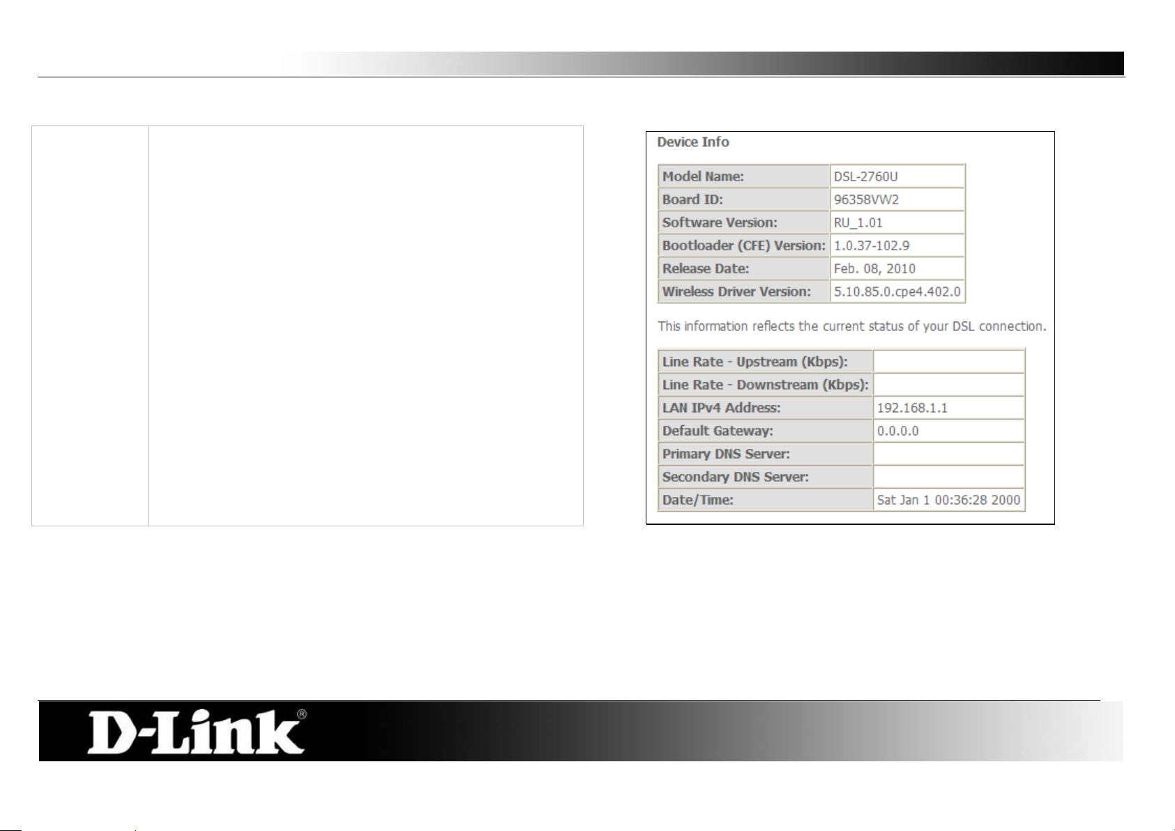
To access the Device Info windo w, click either the Device Info or Summary button in the Device Info directory. The following page opens:
Page 18
D-Link DSL-2760U USER’S MANUAL
18
Device Info:
This window displays the current status of your DSL
connection, including the software version, LAN IP address,
and DNS server address.
Summary
Page 19
D-Link DSL-2760U USER’S MANUAL
19
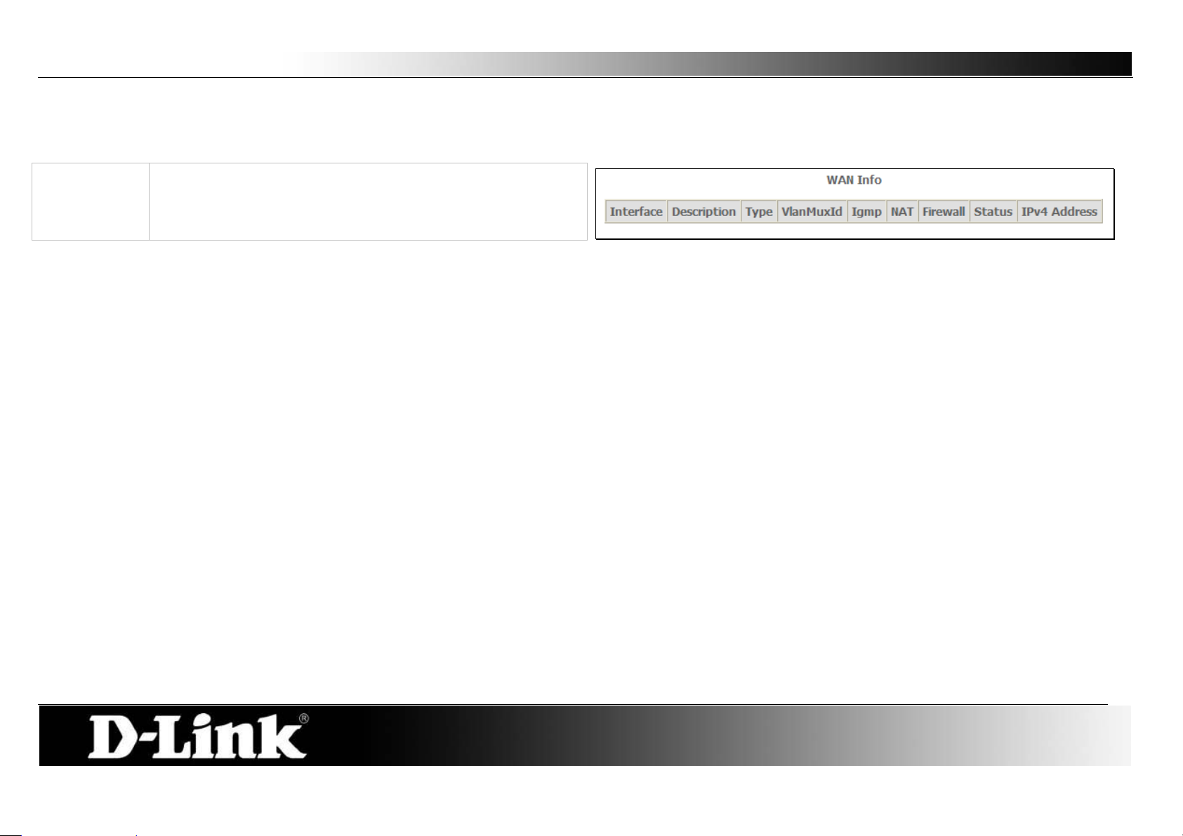
WAN Info:
This window displays the current status of your DSL
WAN
To access the WAN Info window, click the WAN button in the Device Info directory.
connection, including the Interface name, type, VLAN Mux ID,
IGMP, NAT Firewall and IPv4 Address.
Page 20
D-Link DSL-2760U USER’S MANUAL
20
LAN
WAN Services
xTM
Statistics
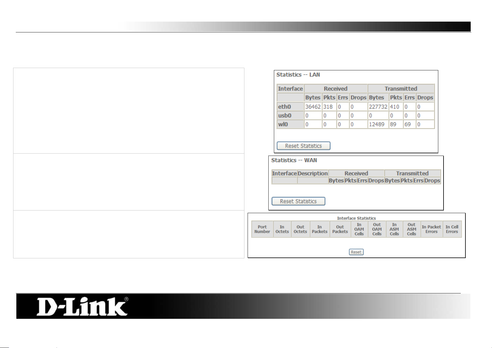
To access the Router’s first Statistics window, click the Statistics button in the Device Info directory.
This window displays the Router’s LAN statistics.
Click the Reset Statistics button to refresh these statistics.
This window displays the Router’s WAN statistics. Click the Reset Statistics
button to refresh these statistics.
This window displays the Router’s xTM statistics.
Click the Reset button to refresh these statistic s.
Page 21
D-Link DSL-2760U USER’S MANUAL
21
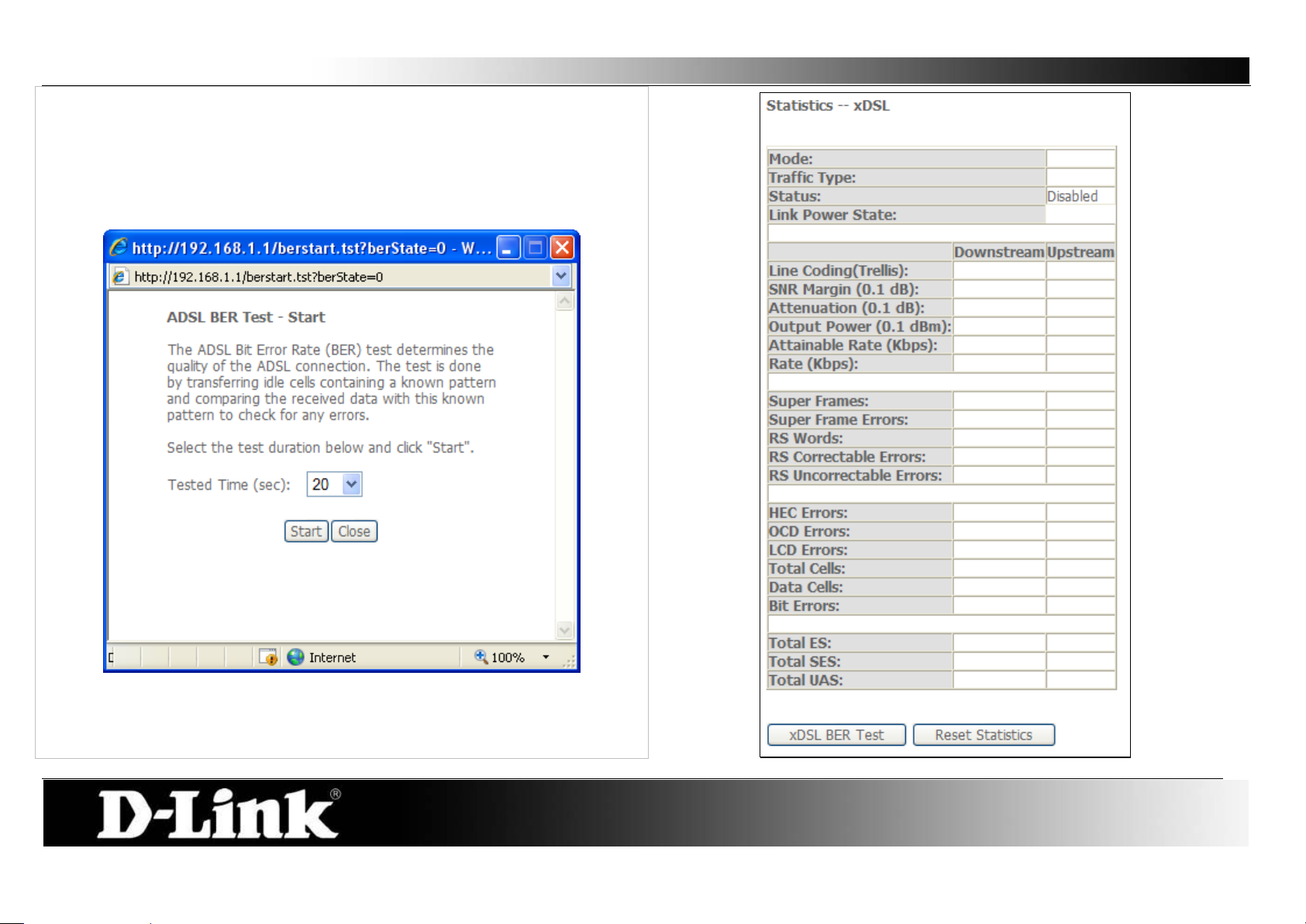
xDSL
This window displays the Router’s xDSL statistics.
Click the Reset Statistics button to refresh these statistics.
Click the xDSL BER Test button to access the ADSL Bit Error Rate Test
window displayed below:
Page 22
D-Link DSL-2760U USER’S MANUAL
22
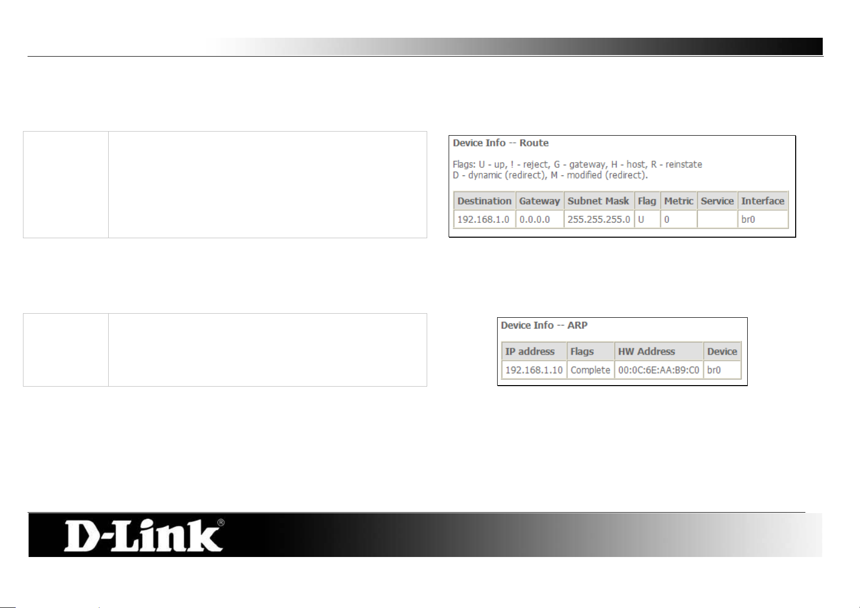
Route:
ARP:
This read-only window displays Addr es s Resolut ion Protocol
Route
To access the Device Info – Route window, click the Route button in the Device Info directory.
This read-only window displays routing info.
ARP
To access the Device Info – ARP window, click the ARP button in the Device Info directory.
info.
Page 23
D-Link DSL-2760U USER’S MANUAL
23
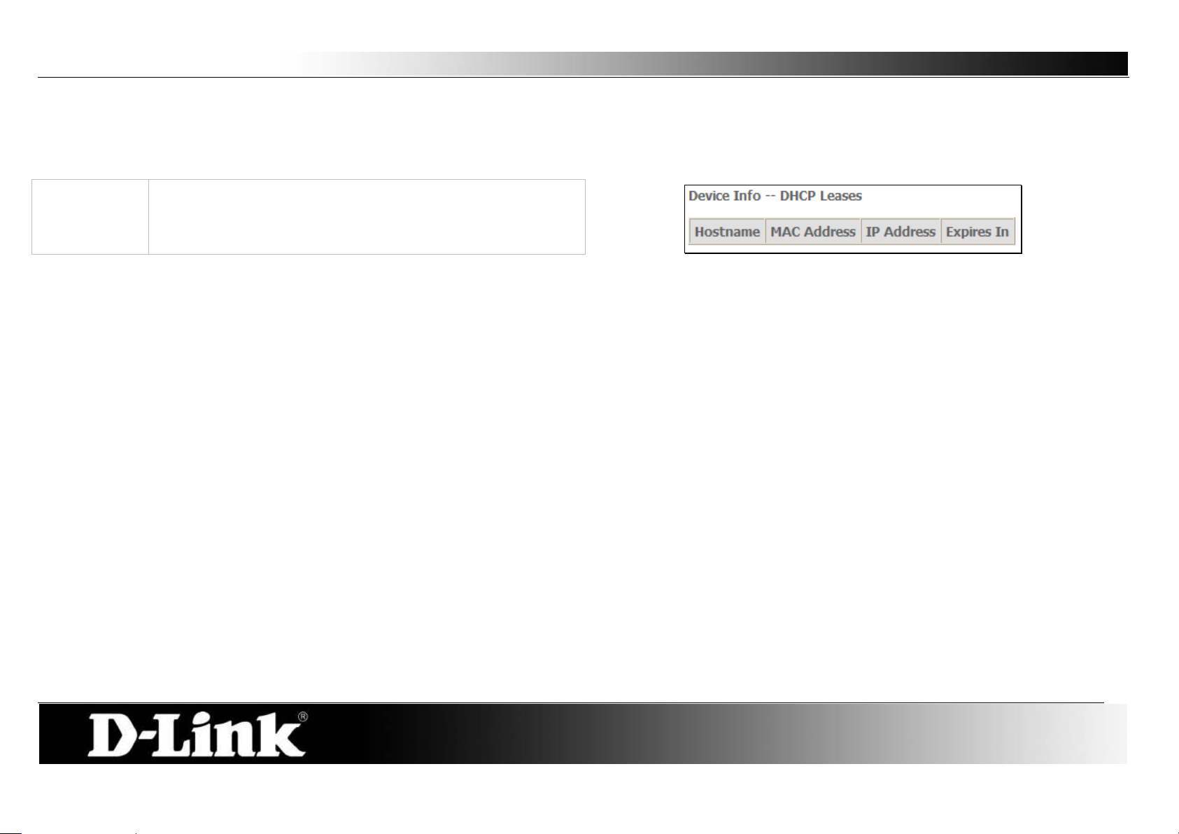
DHCP:
This read-only window displays a list of current DHCP clients
DHCP
To access the Device Info – DHCP window , click the DHCP option in the Device Info directory. This option will only be available if DHCP is enabled in the LAN
settings.
that are connected to this router.
Page 24
D-Link DSL-2760U USER’S MANUAL
24
Advanced Setup
This chapter includes the more advanced features used for network management and security as well as administrative tools to manage t he Rout er view status
and other information used to examine performance and for troubleshooting.
Page 25
D-Link DSL-2760U USER’S MANUAL
25
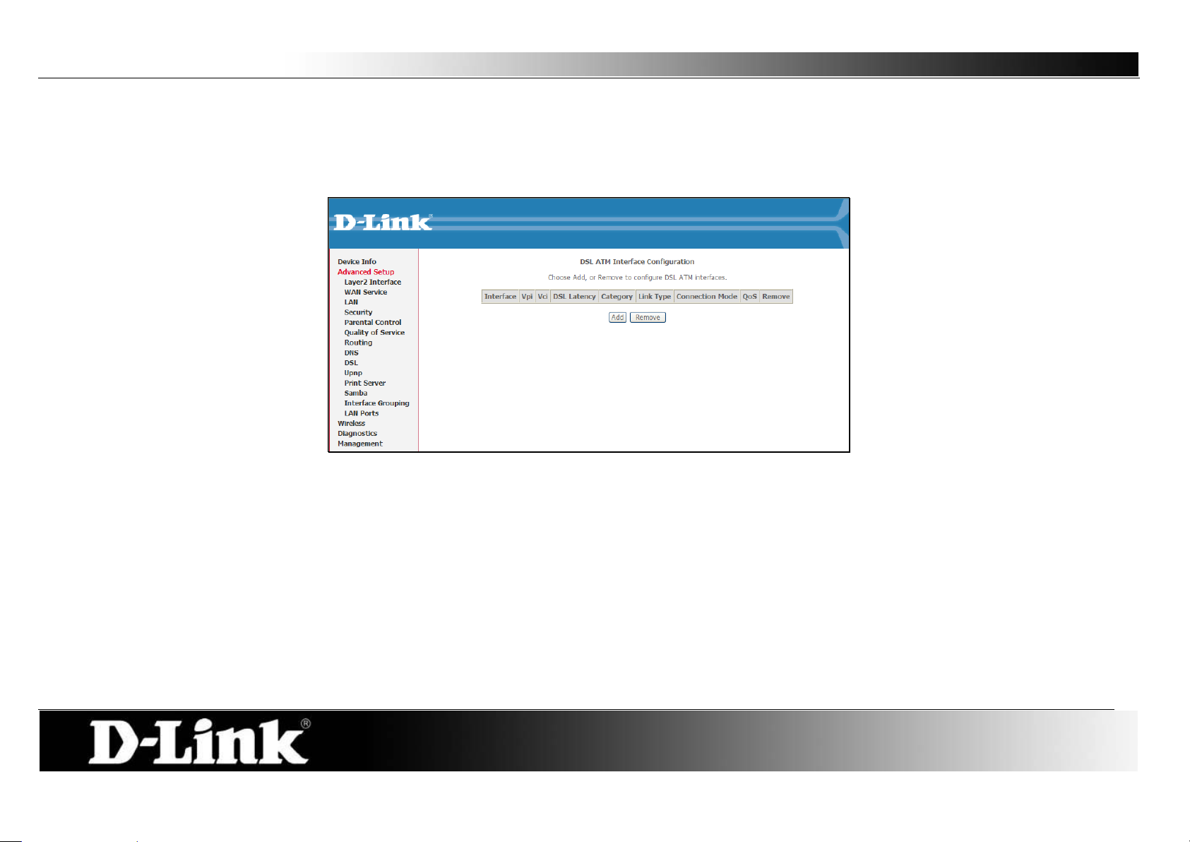
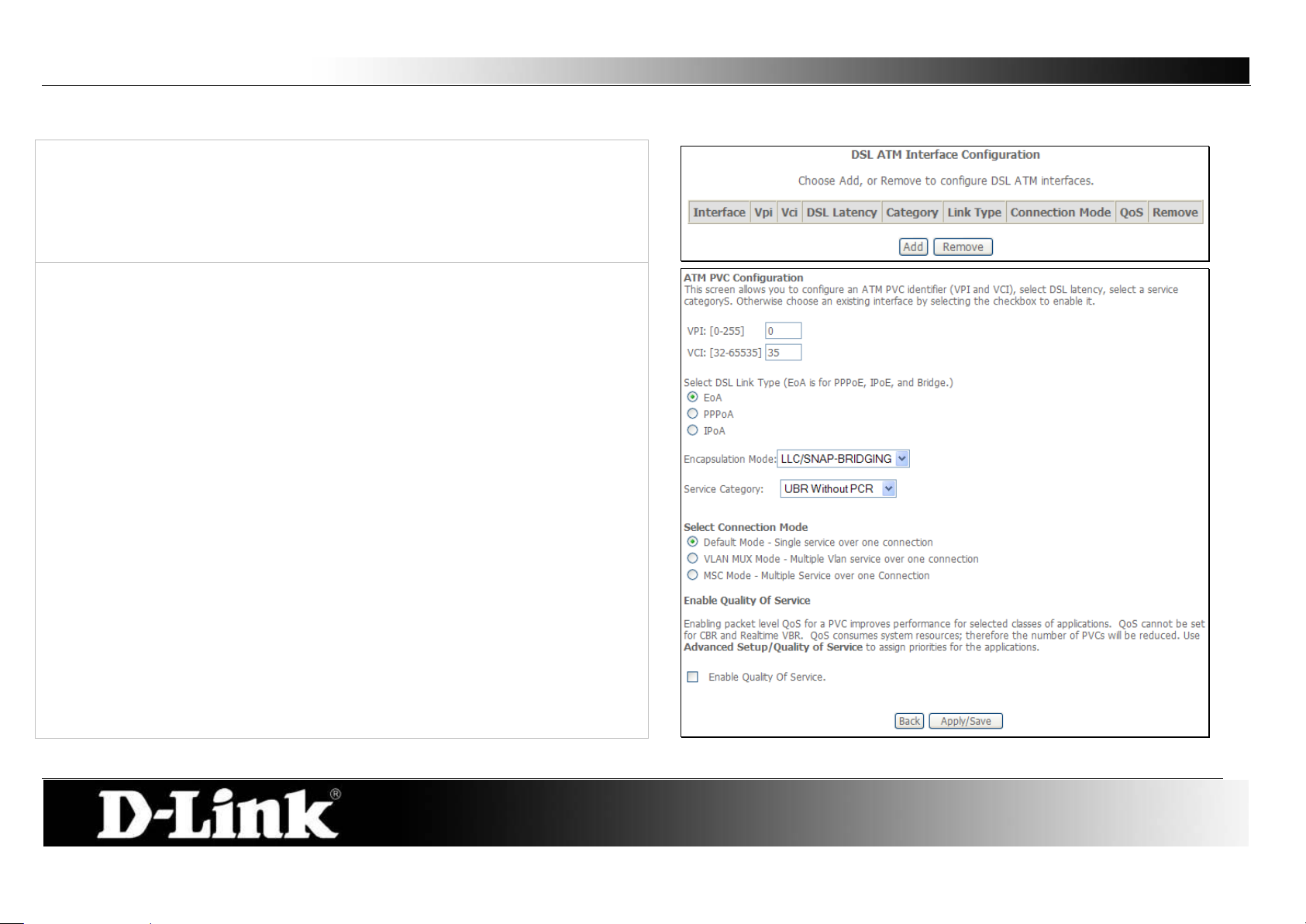
ATM Interface:
This screen allows you to configure an ATM PVC identifier (VPI and VCI),
Layer2 Interface
Choose Add, or Remove to configure DSL ATM int erf aces.
select DSL latency, and select a service category. Otherwise choose an existing
interface by selecting the checkbox to enable it.
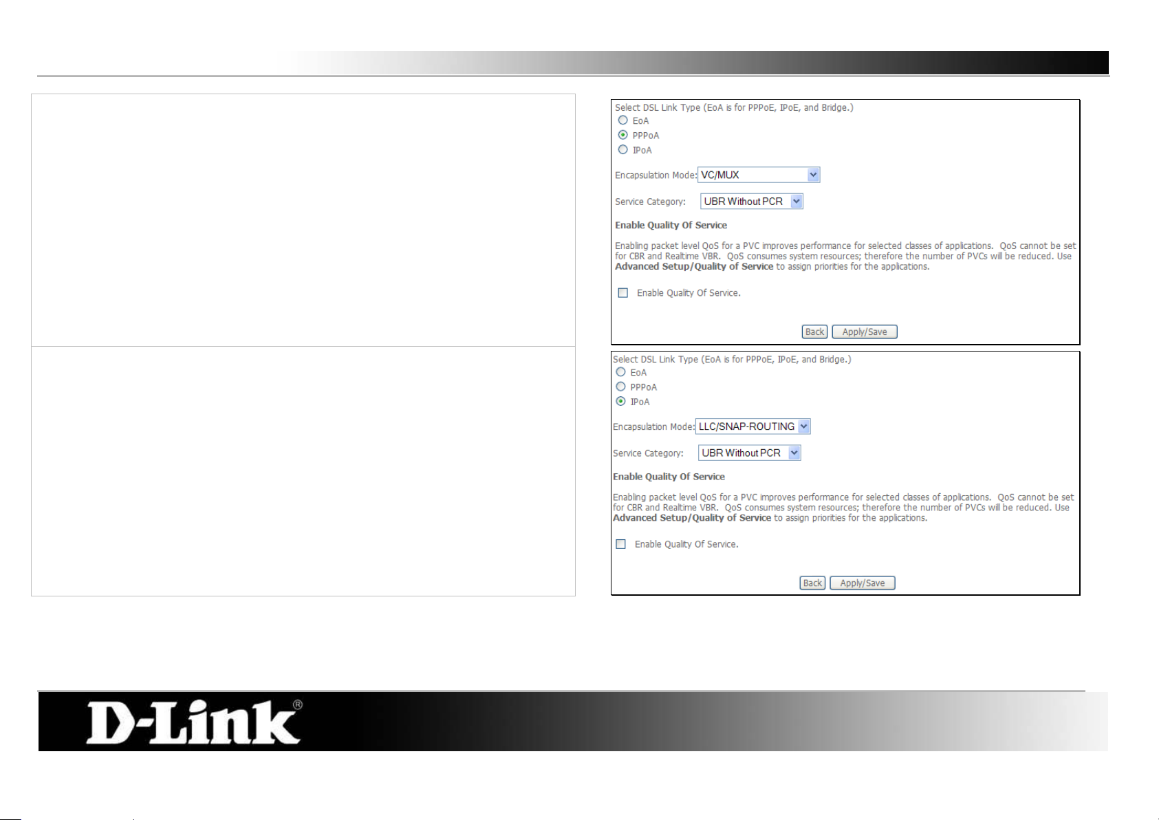
Select Select DSL Link Type (EoA is for PPPoE, IPoE, and Bridge.),
Encapsulation Mode and Service Category.
Enabling packet level QoS for PVC improves performance for selected classes
of applications. QoS cannot be set for CBR and Real-time VBR. QoS
consumes system resources; therefore the number of PVCs will be reduced.
Use Advanced Set up/Q uality of Service to assign priorities for the applications.
Click Apply/Save to add the new ATM Interface.
Page 26
D-Link DSL-2760U USER’S MANUAL
26
Point-to-Point over ATM (PPPoA) is a network protocol for encapsulating PPP
When selecting IPoA, the user can still change the Encap sulation Mode and
frames over A TM.
When selecting PPPoA, the user can still change the Encapsulation Mode
and the Service Category but the Connection Mode will no longer be
available to edit.
the Service Category but the Connection Mode will no longer be available to
edit.
Page 27
D-Link DSL-2760U USER’S MANUAL
27
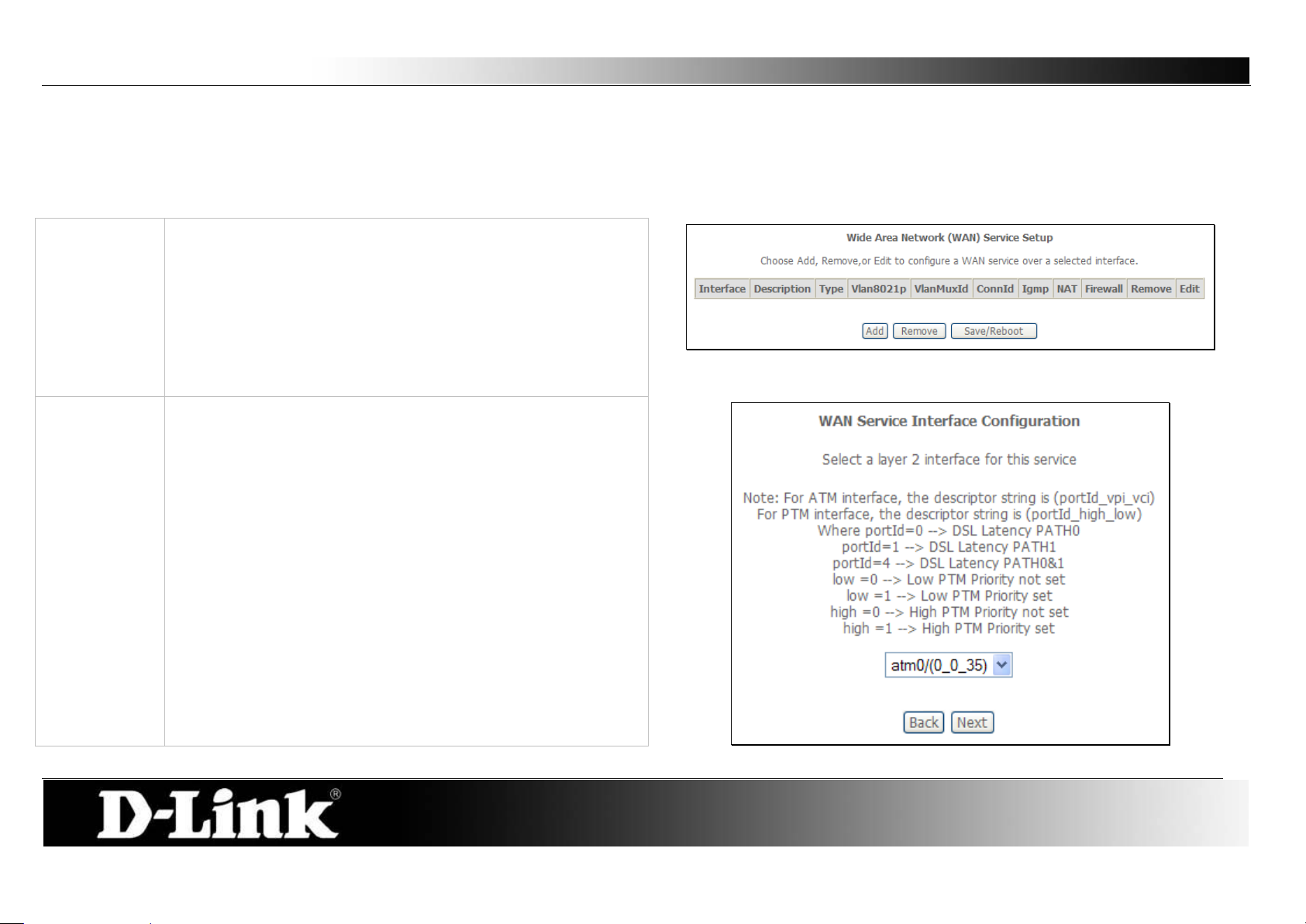
Display:
This window is used to configure the WAN interface. You can
Add:
WAN Service Interface Configuration – Select Interface:
Wide Area Network (WAN) Service
The Wide Area Network (WAN) Service Setup page can be used to setup services regarding the WA N interface. The WA N inter face on this router is the DSL port
side. When setting up the WAN configuration you can choose between various W AN interface connection methods. Before configuring WAN Service, the
information in Layter2 Interface section needs to be configured.
add, delete and modify WAN interfaces on this window.
If you are setting up the WAN interface for the first time, click
the Add button.
Make sure Layer2 Interface is configured before clicking the
Add button.
Select a Layer 2 Interface for this service from the drop-down
menu, and click the Next button.
Page 28
D-Link DSL-2760U USER’S MANUAL
28
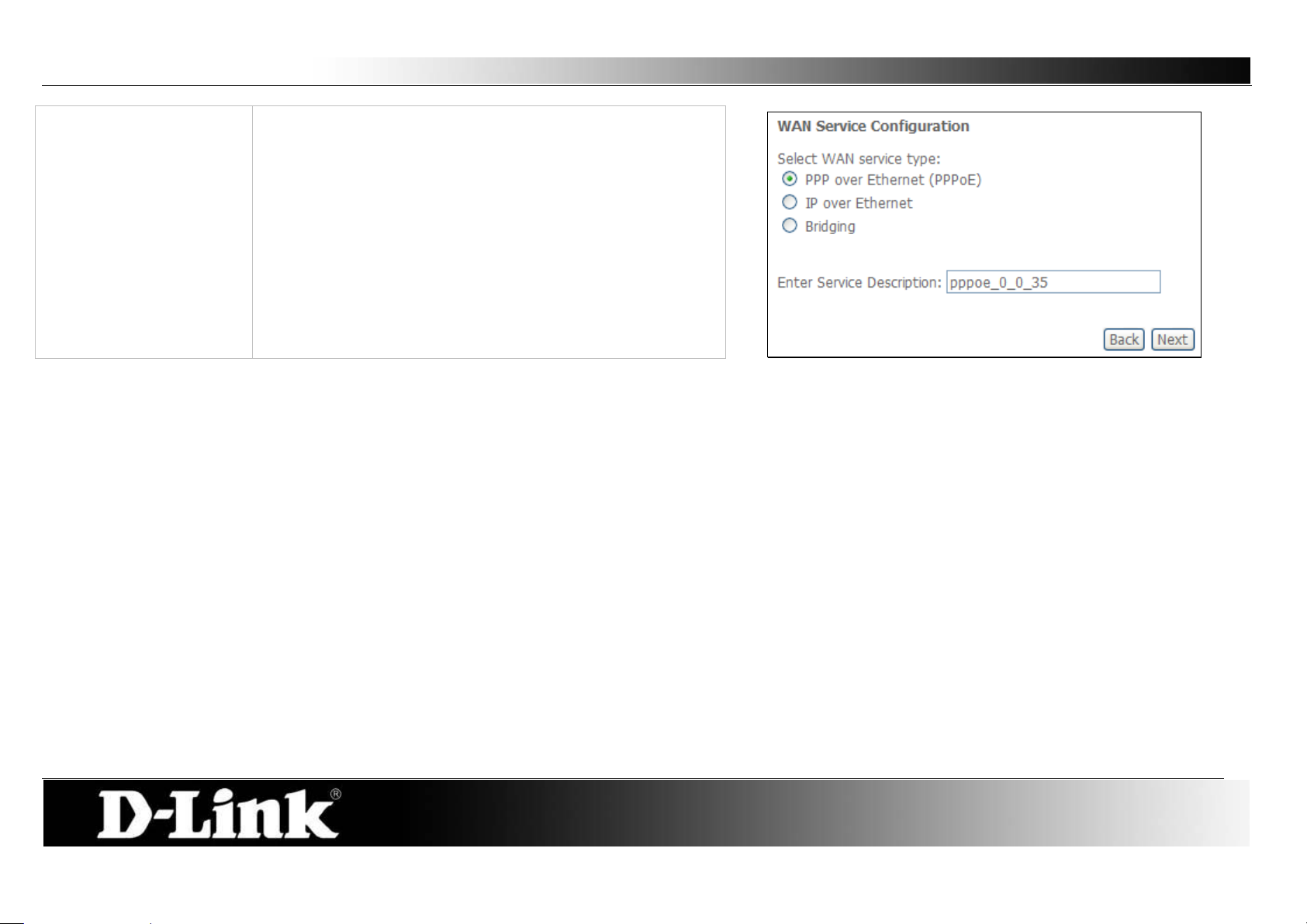
PPP over Ethernet
WAN Service Configuration – PPPoE:
Step 1:
To se tup a PPPoE Interface select the PPP over Ethernet
(PPPoE) and click the Next button.
The Service Description will be added automatically.
Page 29
D-Link DSL-2760U USER’S MANUAL
29
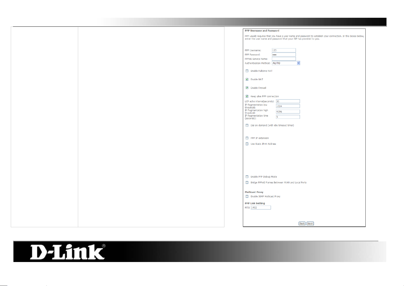
Step 2 - PPPoE:
PPP Username:
PPP Password:
PPPoE Service Name:
Authentication Method:
Enable Fullcone NAT:
Enable NAT:
Enable Firewall:
Keep Alive PPP
connection:
LCP echo interval
(seconds):
IP fragmentation low
threshold:
IP fragmentation high
threshold
IP fragmentation time
(seconds):
Dial on demand:
PPP IP extension:
Static IPv4 Address:
IPv4 Address:
PPP Debug Mode:
Bridge PPPoE:
IGMP Multicast Proxy:
MTU:
Enter the PPP Account Username here.
Enter the PPP Account Password here.
Type in a Ser vice Name here.
Choose an Aut hent ication Method. If you don’t know the
Authentication Method, leave this on Auto.
Tick to enable Fullcone NAT
Tick this option to enable NAT for this connection.
Tick this option to enable firewall for this connection.
Tick the option to enable keep alive function of PPP
connection.
Enter a time in second to determine how often to send an
echo message to an idle link.
The lowest threshold value for the LCP packet.
The highest threshold value for the LCP packet
Enter a time in second for IP fragmentation time.
Tick to enable Dial on Demand.
Tick to enable PPP I P Extension.
Tick to enable Static IP version 4 address.
The option appears when Use Stat ic IPv4 Address is
selected. Enter the Stat ic IP version 4 address used here.
Tick to enable PPP Debug Mode.
Tick to bridge of PPPoE f rames between the WAN interface
and the local ports.
Tick to enable IGMP Multicast Proxy.
Enter a maximum transmission unit value here.
Click Next to continue the setup.
Page 30
D-Link DSL-2760U USER’S MANUAL
30
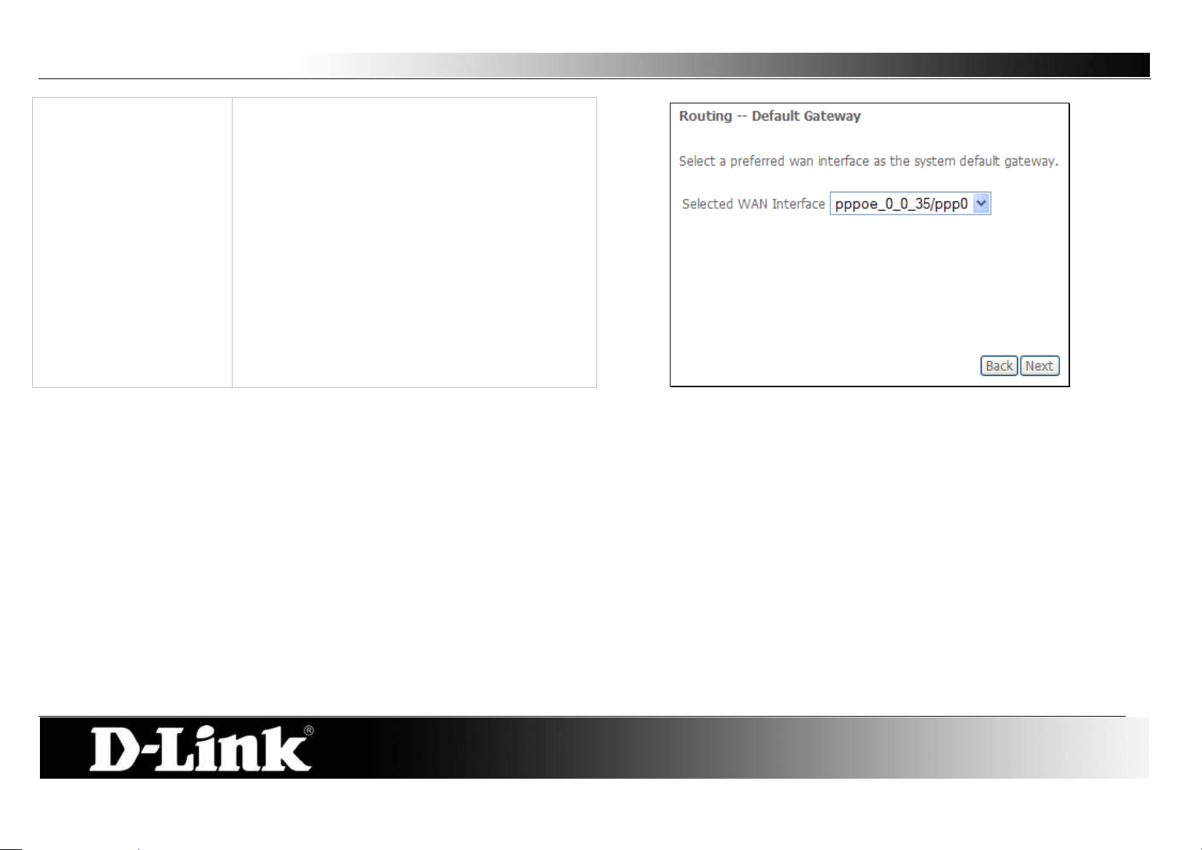
Step 3 - PPPoE
Routing – Default Gateway:
Select a preferred wan interface as the system
default gateway.
Click Next to continue the setup.
Page 31

D-Link DSL-2760U USER’S MANUAL
31
Step 4 – PPPoE
DNS Server Configuration:
Get DNS server information from the selected
WAN interface OR enter s tatic DNS server IP
addresses. If only single PVC with IPoA or static
MER protocol is configured, you must enter static
DNS server IP addresses.
Obtain DNS:
Static DNS:
Select this option to enable automatic DNS
discovery from the WAN interface.
Select this option and enter the DNS IP addresses
if needed.
Click Next to continue the setup
Page 32

D-Link DSL-2760U USER’S MANUAL
32
Step 5 - PPPoE
WAN Setup – Summary:
IP over Ethernet (IPoE)
WAN Service Configuration
Step 1 - IPoE:
Make sure that the settings below match the
settings provided by your ISP.
Click Apply/Save to have this interface to be
effective. Click Back to make any modifications.
To se tup an IPoE Interface select the IP over
Ethernet and click the Next button.
The Service Description will be added
automatically.
Click Next to continue the setup
Page 33

D-Link DSL-2760U USER’S MANUAL
33
Step 2 - IPoE
WAN IP Settings:
Enter information provided to you by your ISP to
configure th e WAN IP settings.
Notice: If Obtai n an IP address automatically is
chosen, DHCP will be enabled for PVC in MER
mode.
If Use the following Static IP address is chosen,
enter the WAN IP address, subnet mask and
interface gateway.
Click Next to continue the setup
Page 34

D-Link DSL-2760U USER’S MANUAL
34
Step 3 - IPoE
Network Address Translation Settings:
Step 4 - IPoE
Routing – Default Gateway:
Network Address Translation (NAT ) allows you to
share one Wide Area Network (WAN) IP address
for multiple computers on your Local Area
Network (LAN).
Select Enable Firewall to use the default firewall
options on this interface.
Select Enable IGMP Multicast to allow IGMP
Multicasting on this interface.
Click Next to continue the setup
Select a preferred wan interface as the system
default gateway.
Click Next to continue the setup.
Page 35

D-Link DSL-2760U USER’S MANUAL
35
Step 5 – IPoE
DNS Server Configuration:
Get DNS server information from the selected
WAN interface OR enter s tatic DNS server IP
addresses. If only single PVC with IPoA or static
MER protocol is configured, you must enter static
DNS server IP addresses.
Obtain DNS:
Static DNS:
Select this option to enable automatic DNS
discovery from the WAN interface.
Select this option and enter the DNS IP addresses
if needed.
Click Next to continue the setup
Page 36

D-Link DSL-2760U USER’S MANUAL
36
Step 6 - IPoE
WAN Setup – Summary:
Bridging
WAN Service Configuration
Step 1 - Bridging:
Make sure that the settings below match the
settings provided by your ISP.
Click Apply/Save to have this interface to be
effective. Click Back to make any modifications.
To se tup a Bridging Interface select the Bridging
and click the Next button.
The Service Description will be added
automatically.
Click Next to continue the setup
Page 37

D-Link DSL-2760U USER’S MANUAL
37
Step 2 - Bridging
WAN Setup – Summary:
Make sure that the settings below match the
settings provided by your ISP.
Click Apply/Save to have this interface to be
effective. Click Back to make any modifications.
Page 38

D-Link DSL-2760U USER’S MANUAL
38
PPP over ATM
WAN Service Interface Configuration:
Step 2 - PPPoA
WAN Service Configuration – PPPoA:
Step 1:
Select a Layer 2 Interface with PPPoA settings for
this service from the drop-down menu, and click
the Next button.
The Service Description will be added
automatically.
Click the Next button.
Page 39

D-Link DSL-2760U USER’S MANUAL
39
Step 3 - PPPoA
PPP Username and Password:
PPP Username:
PPP Password:
Authentication Method:
Enable Fullcone NAT:
Enable NAT:
Enable Firewall:
Keep Alive PPP
connection:
LCP echo interval
(seconds):
IP fragmentation low
threshold:
IP fragmentation high
threshold
IP fragmentation time
(seconds):
Dial on demand:
PPP IP extension:
Static IPv4 Address:
IPv4 Address:
PPP Debug Mode:
IGMP Multicast Proxy:
MTU:
Enter the PPP Account Username here.
Enter the PPP Account Password here.
Choose an Aut hent ication Method. If you don’t know the
Authentication Method, leave this on Auto.
Tick to enable Fullcone NAT
Tick this option to enable NAT for this connection.
Tick this option to enable firewall for this connection.
Tick the option to enable keep alive function of PPP
connection.
Enter a time in second to determine how often to send an
echo message to an idle link.
The lowest threshold value for the LCP packet.
The highest threshold value for the LCP packet
Enter a time in second for IP fragmentation time.
Tick to enable Dial on Demand.
Tick to enable PPP I P Extension.
Tick to enable Static IP version 4 address.
The option appears when Use Static IPv4 Address is
selected. Enter the Stat ic IP version 4 address used here.
Tick to enable PPP Debug Mode.
Tick to enable IGMP Multicast Proxy.
Enter a maximum transmission unit value here.
Click Next to continue the setup.
Page 40

D-Link DSL-2760U USER’S MANUAL
40
Step 4 - PPPoA
Routing – Default Gateway:
Select a pref erred WAN interface as the system
default gateway.
Click Next to continue the setup.
Page 41

D-Link DSL-2760U USER’S MANUAL
41
Step 5 – PPPoA
DNS Server Configuration:
Get DNS server information from the selected
WAN interface OR enter static DNS server IP
addresses. If only single PVC with IPoA or static
MER protocol is configured, you must enter static
DNS server IP addresses.
Obtain DNS:
Static DNS:
Select this option to enable automatic DNS
discovery from the WAN interface.
Select this option and enter the DNS IP addresses
if needed.
Click Next to continue the setup
Page 42

D-Link DSL-2760U USER’S MANUAL
42
Step 5 - PPPoA
WAN Setup – Summary:
Make sure that the settings below match the
settings provided by your ISP.
Click Apply/Save to have this interface to be
effective. Click Back to make any modifications.
Page 43

D-Link DSL-2760U USER’S MANUAL
43
IP over ATM
WAN Service Interface Configuration – IPoA:
Step 2 - IPoA:
WAN Service configuration
Step 1:
Select a Layer 2 Interface with IPoA settings for
this service from the drop-down menu, and click
the Next button.
The Service Description will be added
automatically.
Click the Next button.
Page 44

D-Link DSL-2760U USER’S MANUAL
44
Step 3 - IPoA:
WAN IP Settings
Step 4 – IPoA
Network Address Translation Settings:
WA N IP A ddress:
WAN Subnet Mask:
Enter the WAN IP address used here.
Enter the subnet of the WAN I P address.
Click Next to continue the setup.
Enable NAT:
Enable Firewall:
IGMP Multica st:
Tick this option to enable NAT for this connection.
Tick this option to enable firewall for this
connection.
Tick to enable IGMP Multicast Proxy.
Click Next to continue the setup.
Page 45

D-Link DSL-2760U USER’S MANUAL
45
Step 5 – IPoA
Routing -- Defaul t Gateway
Select a pref erred WAN interface as the system
default gateway.
Click Next to continue the setup
Page 46

D-Link DSL-2760U USER’S MANUAL
46
Step 5 - IPoA
WAN Setup – Summary:
Make sure that the settings below match the
settings provided by your ISP.
Click Apply/Save to have this interface to be
effective. Click Back to make any modifications.
Page 47

D-Link DSL-2760U USER’S MANUAL
47
Display:
To access the Local Area Net work (LAN) Setup
LAN
You can configure the LAN IP address to suit your preference. Many users will find it convenient to use the default settings together wi th DHCP service to
manage the IP settings for their private network. The IP address of the Router is the base addr ess used for DHCP. In order to use the Router for DHCP on your
LAN, the IP address pool used for DHCP must be compatible with the IP address of the Router. The IP addresses available in the DHCP IP addr es s pool will
change automatically if you change the IP address of the Router.
window, click the LAN butt on in the Advanced
Setup directory.
GroupName:
IP Address:
Subnet Mask:
Enable IGMP Snooping:
Standard Mode:
Disable/ Enable DHCP
Blocking Mode:
Server:
Start IP Address:
End IP Address:
Lease Time:
Select the appropriate group name. By default
there is only one group
Enter the LAN IP address for the router here.
Enter the Subnet Mask for the router here.
Tick this option to enable IGMP Snooping.
Select to use Standar d Mode. (If IGMP Snooping
is enabled)
Select to use Blocking Mode. (If IGM P Snoo ping is
enabled)
Choose to enable or disable the DHCP Server
here.
Enter a starting IP Address for the DHCP pool
here.
Enter an end IP Address for the DHCP pool here.
Enter a DHCP Lease Time value here.
To add reserve an IP to a specific host click the
Add Entries button.
Page 48

D-Link DSL-2760U USER’S MANUAL
48
To reserve an IP for a specific host the user must
Static IP Lease List:
All the reserved DHCP client entries will be listed
Second IP Address:
To enable a second LAN interface IP tick this
different IP range than the current first IP Address.
know the specific host’s Mac Address.
Mac Address:
IP Address:
Enter the reserved host’s Mac Address in here.
Enter the reserved host’s IP Address in here.
Click Apply/Save to continue.
here.
option and enter a second IP address and Subnet
Mask for the router here.
Note: The second LAN IP Address must be of a
Page 49

D-Link DSL-2760U USER’S MANUAL
49
To Add a Virtual Server Rule, click the Add button.
NAT – Virtual Servers
Virtual Server allows you to direct incoming traffic from WAN side (identified by Protocol and External port) to the internal server with private IP address on the
LAN side. The Internal port is required only if the external port needs to be converted to a different port number used by the server on the LAN side. The NAT
button appears when configuring WAN interface in PPPoE,or IPoA.
Page 50

D-Link DSL-2760U USER’S MANUAL
50
Select the service name, and enter the server IP address and click
View the newly added rule.
Apply/Save to forward IP packets for this service to the s pecif ied server.
NOTE: The "Internal Port End" cannot be modified directly. Normally, it is set to
the same value as "External Port End". However, if you modify "Internal Port
Start", then "Internal Port End" will be set to the same value as "Internal Port
Start".
A maximum number of 32 entries can be configured.
Page 51

D-Link DSL-2760U USER’S MANUAL
51
To Add a Port Triggering Rule click the Add button.
NAT – Port Triggering
Some applications require that specific ports in the Router's firewall be opened for access by the remote parties. Port Trigger dynamically opens up the 'Open
Ports' in the firewall when an application on the LAN initiates a TCP/UDP connection to a remote p arty using the ' Triggering Ports'. The Router allows the remote
party from the WAN side to establish new connections back to the application on the LAN side using the 'Open Ports'. A maximum 32 entries can be configured.
Page 52

D-Link DSL-2760U USER’S MANUAL
52
Some applications such as games, video conferencing, remote access
View the newly added rule.
applications and others require that specific ports in the Router's firewall be
opened for access by the applications.
You can configure the port settings from this screen by selecting an existing
application or creating your own (Custom application) and click Save/Apply to
add it.
A maximum number of 32 entries can be configured.
Page 53

D-Link DSL-2760U USER’S MANUAL
53
Enter the computer's IP address and click Save/Apply to activate the DMZ
Tick the SIP Enabled check box to enable ALG on this router and click
NAT – DMZ Host
The DSL router will forward IP packets from the WAN that do not belong to any of the applications configured in the Virtual Servers table to the DMZ host
computer.
host.
Clear the IP address field and click Save/Apply to deactivate the DMZ host.
NAT – ALG
ALG, known as Application Level Gateway or Application Layer Gateway, consists of a security component that augments a firewall or NAT employed in a
computer network. The main function for ALG on this gateway is to allow NAT traversal to SIP applications.
Save/Apply.
Page 54

D-Link DSL-2760U USER’S MANUAL
54
IP Filtering - Outgoing
IP Filtering – Incoming
Security – IP Filtering
When a computer connects to the Internet, it begins communicating with other networking device and computers and by the norm is taking a r isk. I nternet
Security is the method to safely secure a local network from unwanted intrusions f r om t he Internet and also to the Internet. This page allow for two main security
methods that can be used. The first method is to block any node and ONLY allowing certain users to connect through this router. The second method is to allow
any node and ONLY blocking certain users to connect through this router.
The basic firewall of this router should be sufficient enough to keep unwanted guests from browsing your network from the Internet. This page will add to this
already applied security feature
This window allows you to create a filter rule to block outgoing IP traffic by
specifying a filter name and at least one condition on this window. All of the
specified conditions in this filter rule must be satisfied for the rule to take effect.
Filters are used to allow or deny LAN or WAN use rs from accessing the Internet
or your internal network. Click the Change Policy to change between BLOCK
and ACCEPT the rules.
If you are setting up the outgoing IP filtering, click the Add button.
The Inbound Filter allows you to create a filter rule to allow incoming IP traf fic
by specifying a filter name and at least one condition on this window. All of the
specified conditions in this filter rule must be satisfied for the rule to take effect.
By default, all incoming IP traf fic from the In ternet is blocked when the firewall is
enabled. Click the Change Policy to change between BLOCK and ACCEPT
the rules.
If you are setting up the incoming IP filtering, click the Add button.
Page 55

D-Link DSL-2760U USER’S MANUAL
55
Outgoing Rule - Add
Incoming Rule - Add
Filter Name:
Protocol:
Source IP Address:
Source Subnet
Mask:
Source Port:
Destination IP
Address:
Destination Subnet
Mask:
Enter a name for the new rule here.
Select the appropriate protocol used here.
Enter the Source IP address here.
Enter the Source Subnet Mask here.
Enter the Source port number here.
Enter the Destination IP address here.
Enter the Destination Subnet Mask here.
Enter the Destination port number here.
Click Apply/Save to add the rule.
Destination Port:
Filter Name:
Protocol:
Source IP Address:
Source Subnet
Mask:
Source Port:
Destination IP
Address:
Destination Subnet
Mask:
Destination Port:
WAN/LAN
Enter a name for the new rule here.
Select the appropriate protocol used here.
Enter the Source IP address here.
Enter the Source Subnet Mask here.
Enter the Source port number here.
Enter the Destination IP address here.
Enter the Destination Subnet Mask here.
Enter the Destination port number here.
Here you can select the appropriate WAN/LAN interface
that this rule will use.
Click Apply/Save to add the rule.
Interfaces:
Page 56

D-Link DSL-2760U USER’S MANUAL
56
IP Filtering – Outgoing
IP Filtering – Incoming
The new rule is added.
The new rule is added.
Page 57

D-Link DSL-2760U USER’S MANUAL
57
MAC Filtering Policy For Each Interface:
Choose Add or Remove to configure MAC filtering rules.
Security – Mac Filtering
MAC Filtering is only effective on ATM PVCs configured in Bridge mode.
FORWARDED means that all MAC layer frames will be FORWARDED except those matching with any of the specified rules in the following table.
BLOCKED means that all MAC layer frames will be BLOCKED except those matching with any of the specified rules in the following table.
WARNING: Changing from one pol icy to anothe r o f an inter face will cause a ll de fined rules for that i nterface to be REM OVED AUTOMATICALLY! You will need to
create new rules for the new policy.
To change the Policy simply tick the Change check box and click the
Change Policy button.
Page 58

D-Link DSL-2760U USER’S MANUAL
58
Create a filter to identify the MAC layer frames by specifying at least one
View the newly added rule.
condition below. If m ultiple conditions are specified, all of them take effect.
Click Save/Apply to save and activate the filter.
Page 59

D-Link DSL-2760U USER’S MANUAL
59
Use this window to deny access to specified MAC address.
MAC address is a specially formatted text string (xx:xx:xx:xx:xx:xx) that
Parental Co ntrol – Time Restriction
Another powerful security feature is by simply making the router inactive or inaccessible at certain times. This page allows the user to setup a time schedule to
block a specific Mac address.
If you are setting up the MAC address blocking, click the Add button.
uniquely identification of a device. This section will allow users to block
devices with certain MAC addresses on the LAN.
To configure for MAC address blocking, enter the username into the
Username field, click Browser’s MAC Address to have MAC address of the
LAN device, or click Other MAC Address and enter a MAC address
manually. Tick the checkboxes for the desired individual days of the week
and enter desired Start Blocking Time and End Blocking Time.
Click the Apply/Save bu t ton to save the configuration
An added rule will look like this.
Page 60

D-Link DSL-2760U USER’S MANUAL
60
Use this window to allow or deny access to a specified URL address.
The new rule is added.
Parental Co ntrol – URL Filter
Another powerful security measure that this router provides is the blocking or allowing of certain URL addresses. This page allows the user to configure URL
filtering.
If you are setting up the URL filtering, click the Add button.
To configure URL Filtering, enter a URL in the URL address space and also
specify the port number. By default a website’s port used is port number
80.
Click Apply/Save to continue.
Page 61

D-Link DSL-2760U USER’S MANUAL
61
Queue Management Configuration
QoS Queue Setup
Quality of Service (QoS)
QoS or Quality of Service allows the router to help prioritize the data packet flow in your Router and network. This is very important for time sensitive appl ications
such as VoIP where it may help prevent dropped calls. Large amounts of non-critical data can be scaled so as not to affect these prioritized sensitive real-time
programs.
If Enable QoS checkbox is selected, choose a default DSCP m ark to
automatically mark incoming traffic without reference to a particular
classifier. Click Apply/Save button to save it.
NOTE: If the Enable QoS checkbox is not selected, all QoS will be disabled
for all interfaces.
NOTE: The default DSCP mark is used to mark all egress packets that do
not match any classification rules.
If you disable WMM function in Wireless Page, queues related to wireless
will not take effects
Click the Add butt on to add a Queue Setup rule.
Page 62

D-Link DSL-2760U USER’S MANUAL
62
Adding a Queue Setup Rule
QoS Classification Se t up
A maximum 32 entries can be configured.
The screen allows you to configure a QoS queue entry and assign it to a
specific network interface. Each of the queues can be configured for a
specific precedence. The queue entry configured here will be used by the
classifier to place ingress packets appropriately. NOTE: Lower integer
values for precedence imply higher priority for this queue relative to others
Click Apply/Save to save and activate the queue.
Choose Add or Remove to configure network traffic classes.
If you disable WMM function in Wireless Page, classification related to
wireless will not take effects.
Page 63

D-Link DSL-2760U USER’S MANUAL
63
Add Network Traffic Class Rule
The screen creates a traffic class rule to classify the upstream traffic, assign
queue which defines the precedence and the interface and optionally
overwrite the IP header DSCP byte. A rule consists of a class name and at
least one condition below. All of the specified conditions in this classification
rule must be satisfied for the rule to take eff ec t.
Click Apply/Save to save and activate the rule.
Page 64

D-Link DSL-2760U USER’S MANUAL
64
Default Gateway
Static Route
Routing
Routing is the process of selecting pa ths in a network along w hich to send netw ork traf fic. The router allows the user to configure routing in 3 ways. Specifying the
Default Route, setting up Static Route or configuring RIP.
Select a preferred wan interface as the system default gateway.
Click Save/Apply to save and activate the rule.
To add a static route, click the Add button.
Page 65

D-Link DSL-2760U USER’S MANUAL
65
Enter the Destination Network Addr es s, Subnet Mask, and the available
Routing Interface Protocol (RIP) Configuration
WAN interface from the User Interface drop-down menu. Click the
Apply/Save button to add the entry to the routing table.
To activate RIP for the WAN I nt erfac e, select the desired RIP version and
operation and place a check in the 'Enabled' checkbox. To stop RIP on the
WAN Interface, uncheck the 'Enabled' checkbox. Click the Apply/Save
button to star/stop RIP and save the configuration.
NOTE: RIP CANNOT BE CONFIGURED on the WAN interface which has
NAT enabled (such as PPPoE).
Page 66

D-Link DSL-2760U USER’S MANUAL
66
DNS Server Configuration
Domain Name Server (DNS) Configuration
The Domain Name System (DNS) is a hierarchical naming system for com puters, services, or any resource participating in the Internet. On this router the user
can either let the WAN interface automatically c onfigure the DNS settings or the user can manually setup the DNS configuration.
Select the configured WAN interface for DNS server information OR enter
the static DNS server IP Addresses for single PVC with IPoA, static IPoE
protocol.
Page 67

D-Link DSL-2760U USER’S MANUAL
67
Dynamic DNS Configurati on
Adding a Rule
Dynamic DNS Configuration
The Dynamic DNS service allows you to alias a dynamic IP address to a static hostname in any o f t he many domains , allowing your DSL router to be more easily
accessed from various locations on the Internet.
Choose Add or Remove to configure Dynamic DNS.
This page allows you to add a Dynamic DNS addr ess from DynDNS.org,
TZO, or dlinkddns.com.
Page 68

D-Link DSL-2760U USER’S MANUAL
68
Viewing
After add the rule you can view it here.
Page 69

D-Link DSL-2760U USER’S MANUAL
69
Modulation, Phone line pairing and Capability
DSL Settings
On the DSL Settings page the user can configure the DSL modulation settings, phone line pairing, test modes and even the tone selection.
Choose the appropriate modulation type needed for the DSL connection
here.
Choose the phone line pair to be used here.
Choose the appropriate capability used here.
Click Apply/Save to save and activate the change.
To change some of t he advanced settings, click the Advanced Settings
button.
Page 70

D-Link DSL-2760U USER’S MANUAL
70
Advanced Settings
Here the user can choose which test mode the router must use.
Click Apply to save and activate the change.
To change the Tone Selection, click the Tone Selection button.
Page 71

D-Link DSL-2760U USER’S MANUAL
71
ADSL Tone Settings
Select the appropriate upstream and downstream tones for your ADSL
Connection.
Click Apply to save and activate the change.
Page 72

D-Link DSL-2760U USER’S MANUAL
72
UPnP Configuration
Print Server Settings
Universal Plug and Play (UPnP) Configuration
UPnP supports zero-configuration networking and automatic discovery for many types of networked devices. When enabled, it allows other devices that support
UPnP to dynamically join a netw ork, obtai n an IP address, convey its capabilities, and learn about the presence and capabili ties of other devices. DHCP and DNS
service can also be used if available on the network. UPnP also allows supported devices to leave a network automatically without adverse effects to the device
or other devices on the network. UPnP is a protocol supported by diverse networking media including Ethernet, Firewire, phone line, and power line networking.
To enable UPnP for any available connection, tick the Enable or disable
UPnP protocol check box and click the Apply/Save button.
Print Server Settings
The router can be configured as a print server. Plug a USB printer into the USB port of the Router to share the printer within the local network. To access the
Print Server window, click the Print Server button in the Advanced Setup directory.
Tick the Enable on-board print server check box. Enter the Printer Name,
and Make and model to make the Router act as a print server.
Click the Save/Apply button to save the changes.
Note: Refer to p.106 Add a Network Printer in Windows XP section to see
how to add a printer to the network.
Page 73

D-Link DSL-2760U USER’S MANUAL
73
USB Storage
Samba USB Storage
Samba is an Open Source/Free Software suite that provides USB storage device file sharing functions. The Router offers two USB ports to plug in USB storage
devices. You can share the files in the USB devices with multiple PCs or laptops within the local network.
To access the Samba Config window, click the Samba Config button in the Advanced Setup directory.
To activate the Samba function, tick the Enable Samba check box, and enter
the NetBIOS Name and Directory Name.
Click Save to save and activate the change.
You can also safely remove the USB storage device by clicking the Unplug
USB button before removing the USB storage device.
Page 74

D-Link DSL-2760U USER’S MANUAL
74
To set up Point-to-Point Tunnel Protocol, tick the Enable check box, enter the
PPTP
To access the PPTP Setting window, click the PPTP button in the Advanced Setup directory.
appropriate information in the fields offered, and then click the Save/Apply
button when you are finished.
Page 75

D-Link DSL-2760U USER’S MANUAL
75
Interface Grouping
Interface Grouping
Interface Grouping supports multiple ports to PVC and bridging groups. Each group will perform as an independent network.
To support this feature, you must create mapping groups with appropriate
LAN and WAN interfaces using the Add button. The Remove button will
remove the grouping and add the ungrouped interfaces to the Default group.
Only the default group has IP interface.
A maximum 16 entries can be configured.
Page 76

D-Link DSL-2760U USER’S MANUAL
76
Adding an interface group
To create a new interface group:
1. Enter the Group name and the group name must be unique and select
either 2. (dynamic) or 3. (static) below:
2. If you like to automatically add LAN clients to a WAN Interface in the new
group add the DHCP vendor ID string. By configuring a DHCP vendor ID
string any DHCP client request with the specified vendor ID (DHCP option
60) will be denied an IP address from the local DHCP server.
3. Select interfaces from the available interface list and add it to the grouped
interface list using the arrow buttons to create the required mapping of the
ports. Note that these clients may obtain public IP addresses
4. Click the Apply/Save button to make the changes effective immediately
IMPORTANT: If a vendor ID is configured for a specific client device please
REBOOT the client device attached to the modem to allow it to obtain an
appropriate IP address.
Page 77

D-Link DSL-2760U USER’S MANUAL
77
LAN Ports Configuration
LAN Ports C onfi guration
Use this page to enable/disable the Virtual LAN Ports feature.
Tick the ENET (1-4) option to include ports 1-4 to the Virtual LAN ports
feature.
Click Apply/Save to save and activate the change.
Page 78

D-Link DSL-2760U USER’S MANUAL
78
Wireless
Wireless communication is to transfer data from point A to point B without the need for physical cabling.
Page 79

D-Link DSL-2760U USER’S MANUAL
79
Basic Configuration
Basic Wireless Configuration
This page allows you to configure basic features of the wireless LAN interface.
You can enable or disable the wireless LAN interface, hide the network from
active scans, set the wireless network name (also known as SSID) and
restrict the channel set based on country requirements.
Click Apply/Save to configure the basic wireless options.
Page 80

D-Link DSL-2760U USER’S MANUAL
80
Wireless Security
Security
This page allows you to c onfigure security features of the w ireless LAN in ter face. You may setup configuration manually or through Wi-Fi Protected Setup (WPS).
The Windows Security Center (WSC) or Act ion Center is a component included with Microsoft's Windows XP (beginning with Service Pack 2), Windows Vista
and Windows 7 operating systems that provides users with the ability to view the status of computer security settings and services.
You can set the network authentication method manually, select ing data
encryption, specifying whether a network key is required to authenticate to
this wireless network and specify the encryption strength.
Click Apply/Save when done.
Page 81

D-Link DSL-2760U USER’S MANUAL
81
Wired Equivalent Privacy (WEP)
WEP is the most basic form of wir eless sec ur it y. There are two variations of
WEP known as Open System and Shared authentication. Open Sys t em
allo ws for a two-way hand shake authentication whereas Shared
authentication allows for a four-way handshake before authentication is
completed.
Using WEP the user will be prompt to select one of the four key spaces and
then to enter a security key according to the strength specified.
Enter 13 ASCII characters or 26 hexadecimal digits for 128-bit encryption
keys
Enter 5 ASCII characters or 10 hexadecimal digits for 64-bit encryption keys
Click Apply/Save to save and activate the changes.
Page 82

D-Link DSL-2760U USER’S MANUAL
82
802.1X
802.1X security allow for the addition of a Radius Server to your network for
added security. This is the strongest form of wireless security available.
When choosing 802.1X you’ll need to specify and Radius Server IP Address.
A Radius Port number and a Radius Key used.
Click Apply/Save to save and activate the change.
Page 83

D-Link DSL-2760U USER’S MANUAL
83
Wi-Fi Protected Access (WPA)-Enterprise
WP A is the replacement for WEP (whi ch is seen b y many administ rators as a
Wi-Fi Protected Access (WPA)-Personal
‘weak’ security method). There are two variations of WPA known as
WPA-EAP (Enterprise) and WPA- PSK (Personal).
When choosing to use WPA-EAP the user has to specify a Radius Server IP
Address, Radius Server Port and a Radius Key.
Click Apply/Save to save and activate the change.
When choosing to use WPA-PSK the user only has to specify a Pre-Shared
Key. Note that there is NO Radius Server settings required when configuring
WPA-PSK.
Enter the Group Key Interval and Encryption if needed.
Click Apply/Save to save and activate the change.
Page 84

D-Link DSL-2760U USER’S MANUAL
84
Wi-Fi Protected Access (WPA2)-Enterprise
Wi-Fi Protected Access (WPA2)-Personal
WPA2 is the upgrade for WPA. WPA2 sorts out a couple of security
vulnerabilities the WPA might encounter. There are also two variations of
WP A2 known as WPA2-EAP (Enterprise) and WPA2- PSK (Personal).
When choosing to use WPA2-EAP the user has to specify a Radius Server
IP Address, Radius Server Port and a Radius Key.
Click Apply/Save to save and activate the change.
When choosing to use WPA2-PSK the user only has to specify a Pre-Shared
Key. Note that there is NO Radius Server settings required when configuring
WPA2-PSK.
Enter the Group Key Interval and Encryption if needed.
Click Apply/Save to save and activate the change.
Page 85

D-Link DSL-2760U USER’S MANUAL
85
Mixed Wi-Fi Protected Access (WP A 2/WPA)-Enterprise
Mixed Wi-Fi Protected Access (WPA2/WPA)-Personal
Mixed WPA2 /WPA-EAP provides the functionality of having wireless clients
running WPA2-EAP or WPA-EAP. It provides backwards compatibility from
WPA2 to WPA.
When choosing to use Mixed WPA2/WPA-EAP the user has to specify a
Radius Server IP Address, Radius Server Port and a Radius Key.
Click Apply/Save to save and activate the change.
When choosing to use Mixed WPA2/WPA-PSK the user only has to specify a
Pre-Shared Key. Note that there is NO Radius Server settings required w hen
configuring Mixed WPA2/WPA-PSK.
Enter the Group Key Interval and Encryption if needed.
Click Apply/Save to save and activate the change.
Page 86

D-Link DSL-2760U USER’S MANUAL
86
Mac Filter
Adding a MAC Address
MAC Filter
Wireless MAC filter is a secur ity option that allows the user to block or allow certain MAC address to and from connecti ng to the Access Point wireless.
Select the appropriate SSID from the drop-down list, and click the radio
buttons under MAC Restrict Mode.
When choosing Allow, all users will be blocked and only the allowing MAC
Addresses will have access to the wireless network.
When choosing Block, all users will be allowed and only the blocked MAC
Addresses will not have access to the wireless network.
Click the Add button to add a new MAC address for the MAC filter.
Enter the Wireless Client’s MAC Address.
Click Apply/Save to save and activate the change.
Page 87

D-Link DSL-2760U USER’S MANUAL
87
Viewing MAC Filter
The new rule should look like this.
Page 88

D-Link DSL-2760U USER’S MANUAL
88
Access Point
Wireless Bridge
This page allows you to configure wireless bridge features of the wireless LAN interface. You can select Wireless Bridge (also known as Wireless Distribution
System) to disable access point functionality. Selecting Access Point enables access point functionality. Wireless bridge functionality will still be available and
wireless stations will be able to associate to the AP.
There are three options to choose in the Bridge Restrict option: Enabled,
Enabled (Scan) and Disabled.
Choose Enabled to allow the user entering the remote bridge’s MAC
address manually.
Choose Enabled (Scan) to allow the user selecting remote bridges from a
list of bridges automatically picked up.
Choose Disabled to disable the wireless bridge option.
Click Apply/Save to save the wireless bridge options.
Page 89

D-Link DSL-2760U USER’S MANUAL
89
Wireless Bridge
There are three options to choose in the Bridge Restrict option: Enabled,
Enabled (Scan) and Disabled.
Choose Enabled to allow the user entering the remote bridge’s MAC
address manually.
Choose Enabled (Scan) to allow the user selecting remote bridges from a
list of bridges automatically picked up.
Choose Disabled to disable the wireless bridge option.
Click Apply/Save to save the wireless bridge options.
Page 90

D-Link DSL-2760U USER’S MANUAL
90
Advanced
Advanced
This page allows you to configure some advanced features of the wireless LAN interface.
The user can select a particular channel on which to operate, force the
transmission rate to a particular speed, set the fragmentation threshold, set
the RTS threshold, set the wakeup interval for clients in power-save mode,
set the beacon interval for the access point, set XPress mode and set
whether short or long preambles are used and more.
Click Apply/Save to configure the advanced wireless options.
Page 91

D-Link DSL-2760U USER’S MANUAL
91
Authenticated Stations
Station Info
This page shows authenticated wireless stations and their status.
This page will display all the current authenticated users connect to this
router wireless.
Click the Refresh button to refresh this page.
Page 92

D-Link DSL-2760U USER’S MANUAL
92
Diagnostics
This router is capable of testing the DSL connection. The individual tests are listed below. If a test displays a fail status, click "Re-Run Diagnostic Tests" at the
bottom of this page to make sure the fail stat us is consistent. If the test continues to fail, click Help and follow the troubleshooting procedures.
Page 93

D-Link DSL-2760U USER’S MANUAL
93
Pass:
Indicates that the Ethernet interface from your computer is connected to the LAN port of your DSL Router. A flashing or solid green LAN
LED on the router also signifies that an Ethernet connection is present and that this test is successful.
Fail:
Indicates that the DSL Router does not detect the Ethernet interface on your computer.
Pass:
Indicates that the USB interface from your computer is connected to the LAN port of your DSL Router.
Fail:
Indicates that the DSL Router does not detect the USB interface on your computer.
Ethernet Connection Test
If the test fails, follow the troubleshooting procedures listed below and re-run the diagnostics tests by clicking the ‘Rerun Diagnostic Tests’ button at the bottom of
this page. If all the tests pass, close and restart your Web browser to access the Internet.
Troubleshooting:
1. If you are not able to access this page, verify that the Ethernet cable from your computer or your hub is connected to the LAN port on DSL Rout er. Reseat
the cable by unplugging both ends and reconnecting them to their respective ports.
2. Turn off the DSL Router, wait 10 seconds and turn it back ON.
3. Make sure you are using the Ethernet cable supplied with your DSL Router
4. With the router on, press the reset button on the DSL Router for at least six seconds and release it. This resets the DSL Router to its default settings. Wait
for the DSL Router to initialize, then close and restart your Web browser. To reconfigure the router, type your DSL Account username and pas sword.
USB Connection Test
If the test fails, follow the troubleshooting procedures listed below and re-run the diagnostics tests by clicking the ‘Rerun Diagnostic Tests’ button at the bottom of
this page. If all the tests pass, close and restart your Web brows er to access the Internet.
Troubleshooting:
1. If there is no connection to the USB port of the DSL Router, this test should fail.
2. If you are not able to access this page, verify that the USB cable from your computer or your hub is connected to the LAN por t on the DSL Router. Reseat
the USB cable by unplugging both ends and reconnecting them to their respective ports.
3. Turn off the DSL Router, wait 10 seconds and turn it back ON.
4. With the router on, press the reset button on the DSL Router for at least six seconds and release it. This resets the DSL Router to its default settings. Wait
for the DSL Router to initialize, then close and restart your Web browser. To reconfigure the router, type your DSL Account username and password.
Page 94

D-Link DSL-2760U USER’S MANUAL
94
Pass:
Indicates that the Wireless interface from your computer is connected to the LAN port of your DSL Router. A flashing or solid green LAN
LED on the router also signifies that a Wireless connection is present and that this test is successful.
Fail:
Indicates that the DSL Router does not detect the Wireless interface on your computer.
Pass:
Indicates that the DSL m odem has detected a DS L signal from the telephone company. A solid DSL LED on the modem also indicates the
detection of a DSL signal from the telephone company.
Fail:
Indicates that the DSL modem does not detect a signal from the telephone company's DSL network. The DSL LED will continue to flash
green.
Wireless Connection Test
If the test fails, follow the troubleshooting procedures listed below and re-run the diagnostics tests by clicking the ‘Rerun Diagnostic Tests’ button at the bottom of
this page. If all the tests pass, close and restart your Web browser to access the Internet.
Troubleshooting:
1. Verify that the Wireless configurations from your computer and your DSL router are matched and corrected.
2. Turn off the DSL Router, wait 10 seconds and turn it back ON.
3. With the router on, press the reset button on the DSL Router for at least six seconds and release it. This resets the DSL Router to its default settings. Wait
for the DSL Router to initialize, then close and restart your Web browser. To reconfigure the router, type your DSL Account username and password.
ADSL Synchronizati on Test
If the test fails, follow the troubleshooting procedures listed below and re-run the diagnostics tests by clicking the ‘Rerun Diagnostic Tests’ button at the bottom of
this page. If all the tests pass, close and restart your Web browser to access the Internet.
Troubleshooting:
1. Make sure your phone line is plugged into the modem.
2. After turning on your DSL modem, wait for at least one minute to establish a connection. Run the diagnostic tests again by clicking the Rerun Diagnostic
Tests button at the bottom of this page.
3. Make sure there is no DSL micro filter on the phone cord connecting the DSL modem to the wall jack.
4. Make sure you are using the phone cord that was supplied wit h your DSL modem or another similar phone cord with four copper wires visible in the plug.
5. If your DSL has been functioning properly for a long period of time and you suddenly are experiencing this problem, there may be a problem with the DSL
network. You may need to wait from 30 minutes to a couple of hours, and if you still do not have a solid DSL LED on your modem, call Technical Support.
6. Turn of f the pow er to the DSL modem, wait 10 seconds and turn it back on. Wai t at least one minute and i f the DSL LED on the modem remains a solid color,
Page 95

D-Link DSL-2760U USER’S MANUAL
95
Pass:
Indicates that the DSL modem can communicate with the DSL provider network.
Fail:
Indicates that the DSL modem may not be able to communicate with the DSL provider network. This test may have an effect on your
able to access the Internet, there is no need to troubleshoot this issue.
close your Web browser and restart it.
ATM OAM Segment Ping Test
Internet connectivity. O ccasionally the DSL provider network may intentionally block this traffic. Therefore if this test fails but you are still
If the test fails, follow the troubleshooting procedures listed below and re-run the diagnostics tests by clicking the ‘Rerun Diagnostic Tests’ button at the bottom of
this page. If all the tests pass, close and restart your Web browser to access the Internet.
Troubleshooting:
NOTE: This test will fail if Test ADSL Synchronization also fails. Troubleshoot the Test ADSL Synchronization test first.
1. Turn off the DSL modem, wait 10 seconds and turn it back on.
2. With the modem on, press the external reset button on the DSL modem for at least six seconds and release it. This resets the DSL modem to its default
settings. Wait for the DSL m odem to completely restart, then close and restart your Web browser. To reconfigure the modem, type your DSL Account
username and password.
3. If this is the first time you are setting up your D SL modem, you may need to reconfigure your VPI/VCI set tings. Cont act ISP Technical Support for assistance.
Page 96

D-Link DSL-2760U USER’S MANUAL
96
Pass:
Indicates that the DSL modem can communicate with the DSL provider network.
Fail:
Indicates that the DSL modem may not be able to communicate with the DSL provider network. Occasionally the DSL provider network
this issue.
ATM OAM End-to-end Ping Test
may intentionally block this traffic. Therefore if this test fails but you are still able to access the Internet, there is no need to troubleshoot
If the test fails, follow the troubleshooting procedures listed below and re-run the diagnostics tests by clicking the ‘Rerun Diagnostic Tests’ button at the bottom of
this page. If all the tests pass, close and restart your Web browser to access the Internet.
Troubleshooting:
NOTE: This test will fail if Test ADSL Synchronization also fails. Troubleshoot the Test ADSL Synchronization test first.
1. Turn off the DSL modem, wait 10 seconds and turn it back on.
2. With the modem on, press the external reset button on the DSL modem for at least six seconds and release it. This resets the DSL modem to its default
settings. Wait for the DSL modem to completely restart, then close and restart your Web browser. To reconfigure the modem, type your DSL Account
username and password.
3. If this is the first time you are setting up your DSL modem, you may need to reconfigure your VPI/VCI settings. C ontact ISP Technical Support for assistance.
Contact ISP Technical Support if you have tried all of the above and still are experiencing a fail condition.
Page 97

D-Link DSL-2760U USER’S MANUAL
97
Management
Page 98

D-Link DSL-2760U USER’S MANUAL
98
Backup
Update Settings
Restore Default Settings
Settings
In the settings section the user can backup and upload the router’s configuration and also perform a factory reset when needed.
This page allows the user to backup the current running configuration of the
router.
Click the Backup Settings button to save the file in a safe location.
This page allows the user the restore a backed up running configuration to
the router.
Click the Browse button and locate the saved backup file. Then click the
Update Settings button to restore the running configuration.
The page allows the user to pe rform a factory reset on the router. Important:
After clicking the Restore Default Settings button, the router will return to
its factory default setup.
This should be the last option when troubleshooting a problem.
Page 99

D-Link DSL-2760U USER’S MANUAL
99
System Log
Configuration
options.
System Log
System Log
The System Log dialog allows you to view the System Log and configure the System Log options.
Click View System Log to view the System Log.
Click Configure System Log to configure the System Log options.
If the log mode is enabled, the system will begin to log all the selected
events.
For the Log Level, all events above or equal to the selected level will be
logged.
For the Display Level, all logged events above or equal to the selected level
will be displayed.
If the selected mode is Remote or Both, events will be sent to the specified
IP address and UDP port of the remote syslog serv er. If the selected mode is
Local or Both, events will be recorded in the local memory.
Select the desired values and click Apply/Save to configure the system log
Click View System Log to view the System Log.
Click Refresh to update the status.
Page 100

D-Link DSL-2760U USER’S MANUAL
100
SNMP Configuration
SNMP Agent
Simple Network Management Protocol (SNMP) allows a management application to retrieve statistics and status from the SNMP ag ent in this device.
Select the desired values and click Save/Apply to configure the SNMP
options.
 Loading...