

Page 1

DSL-2740B
Wireless ADSL2+ Router
User Guide
September 2006
ESL2740BEUA1G
Page 2

FCC Warning
This device complies with part 15 of the FCC Rules. Operation is subject to the following two conditions: (1) This
device may not cause harmful interference, and (2) this device must accept any interference received, including
interference that may cause undesired operation.
This equipment has been tested and found to comply with the limits for a Class B digital device, pursuant to part 15 of
the FCC Rules. These limits are designed to provide reasonable protection against harmful interference in a residential
installation. This generates, uses and can radiate radio frequency energy and, if not installed and used in accordance
with the instructions, may cause harmful interference to radio communications. However, there is no guarantee that
interference will not occur in a particular installation. If this equipment does cause harmful interference to radio or
television reception, which can be determined by turning equipment off and on, the user is encouraged to try to correct
the interference by one or more of the following measures:
- Reorient or relocate the receiving antenna.
- Increase the separation between the equipment and receiver.
- Connect the equipment into an outlet on a circuit different from that to which the receiver is connected.
- Consult the dealer or an experienced radio/TV technician for help.
-
CE Mark Warning
This is a Class B product. In a domestic environment, this product may cause radio interference in which case the user
may be required to take adequate measures.
Page 3

Table Of Contents
BEFORE YOU START ....................................................................................................... V
Installation Overview.........................................................................................................v
Setup Wizard ......................................................................................................................v
Packing List.......................................................................................................................vi
Installation Notes..............................................................................................................vi
INTRODUCTION .................................................................................................................1
Router Description and Operation ...................................................................................1
Router Features .................................................................................................................2
Front Panel Display ...........................................................................................................4
Rear Panel Connections....................................................................................................5
Setting Up a Wireless Network .........................................................................................6
Location and Wireless Operation.....................................................................................7
HARDWARE INSTALLATION ............................................................................................8
Power on Router ................................................................................................................8
Factory Reset Button.........................................................................................................8
BASIC ROUTER CONFIGURATION ................................................................................12
Configuring IP Settings on Your Computer...................................................................12
Access the Configuration Manager................................................................................13
Configure the Router.......................................................................................................14
Wizard...............................................................................................................................15
ADSL.................................................................................................................................27
WLAN................................................................................................................................30
LAN ...................................................................................................................................31
DNS ...................................................................................................................................34
ADVANCED ROUTER MANAGEMENT ...........................................................................36
ADVANCED ADSL............................................................................................................37
ADVANCED WLAN...........................................................................................................38
WLAN SECURITY............................................................................................................. 39
WLAN Filter ......................................................................................................................43
WLAN BRIDGE .................................................................................................................44
WLAN QOS .......................................................................................................................46
FIREWALL ........................................................................................................................48
Page 4

VIRTUAL SERVER ...........................................................................................................50
PORT TRIGGERING .........................................................................................................51
DMZ...................................................................................................................................53
OUTGOING IP FILTER .....................................................................................................54
INCOMING IP FILTER.......................................................................................................56
BRIDGE FILTER ...............................................................................................................57
PARENT CONTROL .........................................................................................................59
URL FILTER......................................................................................................................60
QUALITY OF SERVICE ....................................................................................................61
ROUTING ..........................................................................................................................63
RIP.....................................................................................................................................64
PORT MAPPING ...............................................................................................................66
TOOLS ..............................................................................................................................69
BACKUP SETTINGS.........................................................................................................70
UPDATE SETTINGS .........................................................................................................71
RESTORE DEFAULT........................................................................................................71
TR069 CLIENT ..................................................................................................................72
SNMP CONFIGURATION .................................................................................................73
DDNS.................................................................................................................................74
TIME ..................................................................................................................................76
ACCESS SERVICE ...........................................................................................................77
ACCESS IP .......................................................................................................................79
PASSWORD......................................................................................................................80
UPDATE FIRMWARE .......................................................................................................81
SAVE / REBOOTt .............................................................................................................81
STATUS ............................................................................................................................ 83
DEVICE INFO....................................................................................................................83
ADSL.................................................................................................................................84
LAN ...................................................................................................................................84
WAN ..................................................................................................................................85
ATM...................................................................................................................................86
ROUTE ..............................................................................................................................87
ARP ...................................................................................................................................88
DHCP CLIENTS ................................................................................................................89
WLAN STATION ...............................................................................................................90
SYSTEM LOG ...................................................................................................................91
Page 5

TECHNICAL SPECIFICATIONS .......................................................................................95
CONFIGURING IP SETTINGS ON YOUR COMPUTER ...................................................98
LOW PASS FILTERS FOR DSL .....................................................................................104
Page 6

DSL-2740B Wireless ADSL Router User Guide
About This User Guide
This user’s guide provides instructions on how to install the DSL-2740B Wireless ADSL Router and use it to connect a
computer or Ethernet LAN to the Internet.
Note
If you are using a computer with a functioning Ethernet port, the quickest and easiest way to set up the DSL-2740B is to
insert the Installation CD into the CD-ROM drive of your computer and follow the instructions provided in the Quick
Installation Guide.
You must have an ADSL account setup in order to use this device for Internet access.
Contact your preferred broadband Internet service provider to set up an account.
Before You Start
Please read and make sure you understand all the prerequisites for proper installation of your new Router. Have all the
necessary information and equipment on hand before beginning the installation.
Installation Overview
The procedure to install the Router can be described in general terms in the following steps:
1. You must have an established ADSL Internet account before this device will be able to connect your
computer or private network to the Internet.
2. Gather information and equipment needed to install the device. Before you begin the actual installation
make sure you have all the necessary information and equipment.
3. Install the hardware, that is, connect the cables (Ethernet and telephone) to the device and connect the
power adapter to power on the Router.
4. There are two options available to configure the Router: use your computer to open the Configuration
Utility found on the CD-ROM and follow the step-by-step instructions; or, use a web browser to access
the web pages used for setting up and managing the Router. In order to access the Router’s web-based
manager, you will need to change the IP settings on your computer to “Obtain an IP address
automatically.” Instructions are provided below on how to properly configure IP settings for Windows XP.
This User Manual contains instruction on how to change IP settings on other Windows operating systems.
If you purchased this Router to share your high-speed Internet connection with other computers, you must
have an established Internet account from an Internet Service Provider (ISP).
5. Use the web-based management software to configure the device to suit the requirements of your ADSL
account.
Setup Wizard
Many users will be able to configure all the settings necessary to use the DSL-2740B with the Setup Wizard. For ADSL
connections that use PPPoE or PPPoA connections, the simplest way to set up the DSL-2740B is to use the Setup
Wizard to configure the Internet connection. Once you access the web interface used to configure the device, just
launch the Setup Wizard to configure your Internet connection.
v
Page 7

DSL-2740B Wireless ADSL Router User Guide
Packing List
Open the shipping carton and carefully remove all items. Make sure that you have the items listed here.
• One DSL-2740B Wireless ADSL Ethernet Router
• One CD-ROM containing the User’s Guide and Quick Installation Guide
• One twisted-pair telephone cable used for ADSL connection
• One straight-through Ethernet cable
• One AC power adapter suitable for your electric service
• One Quick Installation Guide
Installation Notes
In order to establish a connection to the Internet it will be necessary to provide information to the Router that will be
stored in its memory. For some users, only their account information (Username and Password) is required. For others,
various parameters that control and define the Internet connection will be required. You can print out the two pages
below and use the tables to list this information. This way you have a hard copy of all the information needed to setup
the Router. If it is necessary to reconfigure the device, all the necessary information can be easily accessed. Be sure to
keep this information safe and private.
Low Pass Filters
Since ADSL and telephone services share the same copper wiring to carry their respective signals, a filtering
mechanism may be necessary to avoid mutual interference. A low pass filter device can be installed for each telephone
that shares the line with the ADSL line. These filters are easy to install passive devices that connect to the ADSL device
and/or telephone using standard telephone cable. Ask your service provider for more information about the use of low
pass filters with your installation.
Operating Systems
The DSL-2740B uses an HTML-based web interface for setup and management. The web configuration manager may
be accessed using any operating system capable of running web browser software, including Windows 98 SE, Windows
ME, Windows 2000, and Windows XP.
Web Browser
Any common web browser can be used to configure the Router using the web configuration management software. The
program is designed to work best with more recently released browsers such as Opera, Microsoft Internet Explorer®
version 6.0, Netscape Navigator® version 6.2.3, or later versions. The web browser must have JavaScript enabled.
JavaScript is enabled by default on many browsers. Make sure JavaScript has not been disabled by other software (such
as virus protection or web user security packages) that may be running on your computer.
Ethernet Port (NIC Adapter)
Any computer that uses the Router must be able to connect to it through the Ethernet port on the Router. This
connection is an Ethernet connection and therefore requires that your computer be equipped with an Ethernet port as
well. Most notebook computers are now sold with an Ethernet port already installed. Likewise, most fully assembled
desktop computers come with an Ethernet NIC adapter as standard equipment. If your computer does not have an
Ethernet port, you must install an Ethernet NIC adapter before you can use the Router. If you must install an adapter,
follow the installation instructions that come with the Ethernet NIC adapter.
802.11 Wireless LAN Configuration
All the 802.11 wireless LAN settings may be configured on a single page using the web-based manager. For basic
wireless communication you need to decide what channel to use and what SSID to assign. These two settings must be
the same for any wireless workstations or other wireless access point that communicate with the DSL-2740B through
the wireless interface.
vi
Page 8

DSL-2740B Wireless ADSL Router User Guide
Security for wireless communication can be accomplished in a number of ways. The DSL-2740B supports WPA (Wi-Fi
Protected Access), WPA2, and mixed WPA/WPA2. Wireless access can also be controlled by selecting MAC addresses
that are allowed to associate with the device. Please read the section on Wireless Configuration.
Additional Software
It may be necessary to install software on your computer that enables the computer to access the Internet. Additional
software must be installed if you are using the device a simple bridge. For a bridged connection, the information needed
to make and maintain the Internet connection is stored on another computer or gateway device, not in the Router itself.
If your ADSL service is delivered through a PPPoE or PPPoA connection, the information needed to establish and
maintain the Internet connection can be stored in the Router. In this case, it is not necessary to install software on your
computer. It may however be necessary to change some settings in the device, including account information used to
identify and verify the connection.
All connections to the Internet require a unique global IP address. For bridged connections, the global IP settings must
reside in a TCP/IP enabled device on the LAN side of the bridge, such as a PC, a server, a gateway device such as a
router or similar firewall hardware. The IP address can be assigned in a number of ways. Your network service provider
will give you instructions about any additional connection software or NIC configuration that may be required.
Information you will need from your ADSL service provider:
Username
Password
WAN Setting /
Connection Type
This is the Username used to log on to your ADSL service
provider’s network. It is commonly in the form −
user@isp.co.uk Your ADSL service provider uses this to
identify your account.
This is the Password used, in conjunction with the Username
above, to log on to your ADSL service provider’s network.
This is used to verify the identity of your account.
These settings describe the method your ADSL service
provider uses to transport data between the Internet and
your computer. Most users will use the default settings. You
may need to specify one of the following WAN Setting and
Connection Type configurations (Connection Type settings
listed in parenthesis):
PPPoE/PPoA (PPPoE LLC, PPPoA LLC or PPPoA VC-Mux)
Bridge Mode (1483 Bridged IP LLC or
1483 Bridged IP VC-Mux)
IPoA/MER (Static IP Address) (Bridged IP LLC,
1483 Bridged IP VC-Mux, 1483 Routed IP LLC, 1483 Routed
IP VC-Mux or IPoA)
Record info here
Modulation Type
MER (Dynamic IP Address) (1483 Bridged IP LLC or
1483 Bridged IP VC-Mux)
ADSL uses various standardized modulation techniques to
transmit data over the allotted signal frequencies. Some
users may need to change the type of modulation used for
their service. The default DSL modulation (ADSL2+ MultiMode) used for the Router automatically detects all types of
ADSL, ADSL2, and ADSL2+ modulation. However, if you are
instructed to specify the modulation type used for the
vii
Page 9

Security Protocol
VPI
DSL-2740B Wireless ADSL Router User Guide
Router, you may choose among the numerous options
available on the Modulation Type drop-down menu on the
ADSL Configuration window (Advanced > ADSL)
This is the method your ADSL service provider will use to
verify your Username and Password when you log on to their
network. Your Router supports the PAP and CHAP protocols.
Most users will not be required to change this setting. The
Virtual Path Identifier (VPI) is used in conjunction with the
Virtual Channel Identifier (VCI) to identify the data path
between your ADSL service provider’s network and your
computer. If you are setting up the Router for multiple virtual
connections, you will need to configure the VPI and VCI as
instructed by your ADSL service provider for the additional
connections. This setting can be changed in the WAN
Settings window of the web management interface.
VCI
IP Address
(RADIUS server)
Port
Key
The Setup Wizard can be used to configure the Internet connection for most users.
Note
Most users will not be required to change this setting. The
Virtual Channel Identifier (VCI) used in conjunction with the
VPI to identify the data path between your ADSL service
provider’s network and your computer. If you are setting up
the Router for multiple virtual connections, you will need to
configure the VPI and VCI as instructed by your ADSL service
provider for the additional connections. This setting can be
changed in the WAN Settings window of the web
management interface.
For WPA security.
For WPA security.
For WPA security.
viii
Page 10

DSL-2740B Wireless ADSL Router User Guide
Information you will need about your DSL-2740B Wireless ADSL Router:
Username
Password
LAN IP addresses for
the DSL-2740B
LAN Subnet Mask for
the DSL-2740B
This is the Username needed access the Router’s
management interface. When you attempt to connect
to the device through a web browser you will be
prompted to enter this Username. The default
Username for the Router is “admin.” The user cannot
change this.
This is the Password you will be prompted to enter
when you access the Router’s management interface.
The default Password is “admin.” The user may change
this.
This is the IP address you will enter into the Address
field of your web browser to access the Router’s
configuration graphical user interface (GUI) using a
web browser. The default IP address is 192.168.1.1.
This may be changed to suit any IP address scheme
the user desires. This address will be the base IP
address used for DHCP service on the LAN when DHCP
is enabled.
This is the subnet mask used by the DSL-2740B, and
will be used throughout your LAN. The default subnet
mask is 255.255.255.0. This can be changed later.
Record info here
Information you will need about your LAN or computer:
If your computer has an Ethernet NIC, you can
connect the DSL-2740B to this Ethernet port using an
Ethernet NIC
DHCP Client status
It is recommended that your collect and record this information here, or in some other secure place, in case you have to
re-configure your ADSL connection in the future.
Once you have the above information, you are ready to setup and configure your DSL-2740B Wireless ADSL Router.
Ethernet cable. You can also use the Ethernet ports
on the DSL-2740B to connect to other computer or
Ethernet devices.
Your DSL-2740B ADSL Router is configured, by
default, to be a DHCP server. This means that it can
assign an IP address, subnet mask, and a default
gateway address to computers on your LAN. The
default range of IP addresses the DSL-2740B will
assign are from 192.168.1.2 to 192.168.1.254.
Your computer (or computers) needs to be configured
to Obtain an IP address automatically (that is,
they need to be configured as DHCP clients.)
Record info here
ix
Page 11

DSL-2740B Wireless ADSL Router User Guide
1
Introduction
This section provides a brief description of the Router, its associated technologies, and a list of Router features.
Router Description and Operation
The DSL-2740B Wireless ADSL Router is designed to provide connectivity for your private Ethernet LAN, and
802.11b/g/n-draft wireless LAN to the Internet via an ADSL connection.
The Router is easy to install and use. Standard Ethernet ports are used to connect to computer or other Ethernet devices.
The 802.11 wireless interface provides connectivity to 802.11b/g/n-draft wireless devices.
802.11n-draft Wireless
The embedded 802.11 wireless access point provides Internet access and connectivity to the Ethernet for 802.11b,
802.11g, and 802.11n-draft wireless workstations. IEEE 802.11n-draft is fully compatible with IEEE 802.11b/g wireless
devices. The 802.11n-draft standard supports data transfer rates of up to 270 Mbps. The wireless Router supports 64-bit
and 128-bit WEP encryption.
ADSL
Asymmetric Digital Subscriber Line (ADSL) is a broadband network technology that utilizes standard twisted-pair
copper wire telephone lines to enable broadband high-speed digital data transmission and bandwidth hungry
applications for business and residential customers.
ADSL routers and modems provide faster downloads and more reliable connectivity to the user without loss of quality
or disruption of voice/fax telephone capabilities.
ADSL2+ provides a dedicated service over a single telephone line operating at speeds of up to 24Mbps downstream and
up to 1Mbps upstream, depending on local telephone line conditions. A secure point-to-point connection is established
between the user and the central office of the service provider.
D-Link ADSL devices incorporate the recommendations of the ADSL Forum regarding framing, data format, and upper
layer protocols.
1
Page 12

DSL-2740B Wireless ADSL Router User Guide
Router Features
The DSL-2740B ADSL Router utilizes the latest ADSL enhancements to provide a reliable Internet portal suitable for
most small to medium sized offices. DSL-2740B advantages include:
• PPP (Point-to-Point Protocol) Security – The DSL-2740B ADSL Router supports PAP (Password Authentication
Protocol) and CHAP (Challenge Handshake Authentication Protocol) for PPP connections.
• DHCP Support – Dynamic Host Configuration Protocol automatically and dynamically assigns all LAN IP
settings to each host on your network. This eliminates the need to reconfigure every host whenever changes in
network topology occur.
• Network Address Translation (NAT) – For small office environments, the DSL-2740B allows multiple users on
the LAN to access the Internet concurrently through a single Internet account. This provides Internet access to
everyone in the office for the price of a single user.
NAT improves network security in effect by hiding the private network behind one global and visible IP address.
NAT address mapping can also be used to link two IP domains via a LAN-to-LAN connection.
• TCP/IP (Transfer Control Protocol/Internet Protocol) – The DSL-2740B supports TCP/IP protocol, the
language used for the Internet. It is compatible with access servers manufactured by major vendors.
• RIP-1/RIP-2 – The DSL-2740B supports both RIP-1 and RIP-2 exchanges with other routers. Using both versions
lets the Router to communicate with all RIP enabled devices.
• Static Routing – This allows you to select a data path to a particular network destination that will remain in the
routing table and never “age out”. If you wish to define a specific route that will always be used for data traffic
from your LAN to a specific destination within your LAN (for example to another router or a server) or outside
your network (to an ISP defined default gateway for instance).
• Default Routing – This allows you to choose a default path for incoming data packets for which the destination
address is unknown. This is particularly useful when/if the Router functions as the sole connection to the Internet.
• ATM (Asynchronous Transfer Mode) – The DSL-2740B supports Bridged Ethernet over ATM (RFC1483), IP
over ATM (RFC1577) and PPP over ATM (RFC 2364).
• Precise ATM Traffic Shaping – Traffic shaping is a method of controlling the flow rate of ATM data cells. This
function helps to establish the Quality of Service for ATM data transfer.
• High Performance – Very high rates of data transfer are possible with the Router. Up to 24Mbps downstream bit
rate using the G.dmt standard. (For ADSL2+)
• Full Network Management – The DSL-2740B incorporates SNMP (Simple Network Management Protocol)
support for web-based management and text-based network management via Telnet connection.
• Telnet Connection – The Telnet enables a network manager to access the Router’s management software remotely.
• Easy Installation – The DSL-2740B uses a web-based graphical user interface program for convenient
management access and easy set up. Any common web browser software can be used to manage the Router.
2
Page 13

DSL-2740B Wireless ADSL Router User Guide
Standards Compatibility and Compliance
The DSL-2740B complies with or is compatible with the following standards as recognized by their respective agencies.
• ITU G.992.1 (G.DMT) compliant
• ITU G.992.2 (G.lite “Splitterless ADSL”) compliant
• ITU-T Rec. I.361 compliant
• RFC 791 Internet Protocol compliant
• RFC 792 UDP compliant
• RFC 826 Address Resolution Protocol compliant (ARP) compliant
• RFC 1058 Routing Information Protocol (RIP) compliant
• RFC 1334 PPP Authentication Protocol compliant
• RFC 1389 Routing Information Protocol 2 (RIP2) compliant
• RFC 1483 IP over AAL5/ Bridged Ethernet over AAL5 compliant
• RFC 1661 Point to Point Protocol (PPP) compliant
• RFC 1877 Automatic IP assignment compliant
• RFC 1994 Challenge Handshake Authentication Protocol compliant
• Supports DHCP functions including: automatic assignment of IP address, use of subnet mask and default
gateway and provision of DNS server address for all hosts
• RFC 2364 PPP over ATM compliant (PPPoA) compliant
• RFC 2516 PPP over Ethernet compliant (PPPoE) compliant
• RFC 2684 Bridged/Routed Ethernet over ATM compliant
• IEEE 802.3 compliant
• IEEE 802.3u compliant
• IEEE 802.1d compliant
• IEEE 802.3x compliant
• Embedded web server support
• Supports Dynamic Learning
• Supports Static Routing
• Supports NAPT for up to 4096 connections
• Supports DHCP for up to 253 hot connections
• Supports IGMP
• Supports DVMRP
• Supports ATM Forum UNI 3.1/4.0
• Supports ATM VCC (Virtual Channel Circuit) for up to eight sessions
• Supports Telnet and TFTP
Supports back pressure for half-duplex
•
3
Page 14
DSL-2740B Wireless ADSL Router User Guide
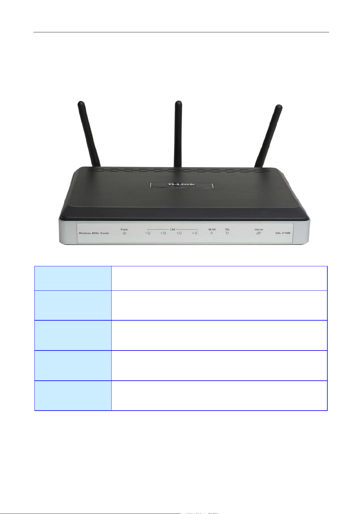
Front Panel Display
Place the Router in a location that permits an easy view of the LED indicators on the front panel.
The LED indicators on the front panel include Power, LAN 1-4, WLAN, DSL, and Internet. The LAN, WLAN, and
Internet indicators monitor link status and activity.
Power
LAN
WLAN
DSL
Internet
Steady green light indicates the unit is powered on. When the device is
powered off this remains dark.
A solid green light indicates a valid link on startup. These lights blink when
there is activity currently passing through the Ethernet port.
Steady green light indicates a wireless connection. A blinking green light
indicates activity on the WLAN interface
Steady green light indicates a valid ADSL connection. This will light after the
ADSL negotiation process has been settled. A blinking green light indicates
activity on the WAN (ADSL) interface.
Steady green light indicates a successful Internet connection. Steady red
light indicates failed Internet connection. Dark if no WAN protocol is
configured.
4
Page 15
DSL-2740B Wireless ADSL Router User Guide
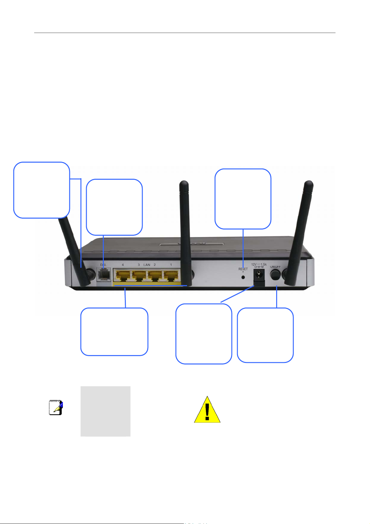
Rear Panel Connections
All cable connections to the Router are made at the rear panel. Connect the power adapter here to power on the Router.
Use the Reset button to restore the settings to the factory default values in the next chapter for instructions on using the
reset button).
Connect network cables:
1. Insert the ADSL (telephone) cable included with the Router into the ADSL port and then connect the cable to
your telephone line.
2. Insert one end of the Ethernet cable into one of the LAN ports on the back panel of the Router and the other
end of the cable to an Ethernet Adapter or available Ethernet port on your computer.
Antenna
For wireless
operation, mount
the antenna on the
threaded antenna
post.
ADSL port
Use the ADSL
cable to connect to
the your telephone
line (RJ-11 port)
Ethernet ports
Use the Ethernet ports
to connect the Router
to your Ethernet LAN
or Ethernet devices
Reset button
To manually reset,
depress button
with the power on
for at least seven
seconds
Power insert
Use the adapter
shipped with the
Router to connect
to power source
Power button
Push in to power-on
the Router. Push
again to power-off
the Router
To manually
reboot the
Note
Router,
disconnect and
then reconnect
the power.
WARNING!
5
Using a power supply with a
different voltage rating will
damage the device and void
the warranty of this product.
Page 16

DSL-2740B Wireless ADSL Router User Guide
Setting Up a Wireless Network
In order to get the best performance from the wireless component of the Router, you should have some basic
understanding of how wireless networks operate. Wireless networking is a relatively new technology and there are more
factors to consider when setting up or designing a wireless network than designing a wired network. If you are setting
up a wireless network, especially if you are using multiple access points and/or covering a large area, good planning
from the outset can ensure the best possible reliability, performance, coverage and effective security.
Radio
Wireless local network (as called WI-FI) devices such as notebook computers and wireless access points use
electromagnetic waves within a broad, unlicensed range of the radio spectrum (between 2.4GHz and 2.5GHz) to
transmit and receive radio signals. A wireless access point (AP) becomes a base station for the wireless nodes (notebook
computer for example) in its broadcast range. Often a wireless access point such as the AP embedded in the DSL2740B, will also provide a connection to a wired network - usually Ethernet - and ultimately an Internet connection. The
IEEE 802.11 standard precisely defines the encoding techniques used to digitally used for data transmission. The DSL2740B can be used by IEEE 802.11g and 802.11b devices. These two standards are compatible but use different
algorithms for data transmission.
802.11g uses a method called Orthogonal Frequency Division Multiplexing (OFDM) for transmitting data at higher data
rates. OFDM is a more efficient encoding method than Direct Sequence Spread Spectrum (DSSS) transmission, the
method used by 802.11b devices. However, in order to support different data transmission rates while also be
compatible with 802.11b, 802.11g uses a combination of OFDM and DSSS when 802.11b devices are present.
Range
An access point will send and receive signals within a limited range. Also, be aware that the radio signals are emitted in
all directions giving the access point a spherical operating range. The physical environment in which the AP is
operating can have a huge impact on its effectiveness. If you experience low signal strength or slow throughput,
consider positioning the Router in a different location. See the discussion below concerning the wireless environment
and location of the AP (DSL-2740B).
SSID and Channel
Wireless networks use an SSID (Service Set Identifier) as means of identifying a group of wireless devices, similar to a
domain or subnet. This allows wireless devices to roam from one AP to another and remain connected. Wireless devices
that wish to communicate with each other must use the same SSID. Several access points can be set up using the same
SSID so that wireless stations can move from one location to another without losing connection to the wireless network.
The embedded wireless access point of the Router operates in Infrastructure mode. It controls network access on the
wireless interface in its broadcast area. It will allow access to the wireless network to devices using the correct SSID
after a negotiation process takes place. By default, the DSL-2740B broadcasts its SSID so that any wireless station in
range can learn the SSID and ask permission to associate with it. Many wireless adapters are able to survey or scan the
wireless environment for access points. An access point in Infrastructure mode allows wireless devices to survey that
network and select an access point with which to associate. You may disable SSID broadcasting in the web manager’s
wireless menu.
In addition, the AP can use different channels (frequency bands) to avoid unwanted overlap or interfere between control
zones of separate APs. Wireless nodes must use the same SSID and the same channel as the AP with which it wishes to
associate. However, because of the nature of the CSMA/CA (carrier sense multiple access with collision avoidance)
protocol, using the same channel on two different APs can contribute significantly to wireless congestion. If you are
using multiple APs on your network and are experiencing low throughput or significant transmission delay, carefully
consider how channels are assigned to the different APs.
Wireless Security
Various security options are available on the DSL-2740B including WPA, WPA2, and mixed WPA/WPA2 (including
PSK). Authentication may use an open system or a shared key. Read below for more information on configuring
security for the wireless interface.
6
Page 17

DSL-2740B Wireless ADSL Router User Guide
Location and Wireless Operation
Many physical environmental factors can impact wireless networks. Radio waves are used to carry the encoded data
between devices. These radio transmissions can become degraded due to signal attenuation, multi-path distortion and
interference or noise. Attenuation simply means that the strength of the signal weakens with the distance it travels, even
if the transmission path is unobstructed. Multi-path distortion occurs when radio signals bounce off objects like walls,
ceilings, metal appliances, etc. This may cause a signal to be duplicated, with each separate yet identical signal arriving
at a receiver at different times. Interference and noise from electrical devices such as microwave ovens, fluorescent
lights, automobile engines and other radio emitting devices can cause signal degradation. With all this in mind, choose a
location for all your access points including the DSL-2740B.
The access point can be placed on a shelf or desktop, ideally you should be able to see the LED indicators on the front if
you need to view them for troubleshooting.
Wireless networking lets you access your network from nearly anywhere you want. However, the number of walls,
ceilings, or other objects that the wireless signals must pass through can limit signal range. Typical ranges vary
depending on the types of materials and background RF noise in your home or business. To range and signal strength,
use these basic guidelines:
1. Keep the number of walls and ceilings to a minimum: The signal emitted from Wireless LAN devices can
penetrate through ceilings and walls. However, each wall or ceiling can reduce the range of Wireless LAN
devices from 1 to 30M. Position your wireless devices so that the number of walls or ceilings obstructing the
signal path is minimized.
2. Consider the direct line between access points and workstations: A wall that is 0.5 meters thick, at a 45-
degree angle appears to be almost 1 meter thick. At a 2-degree angle, it is over 14 meters thick. Be careful to
position access points and client adapters so the signal can travel straight through (90º angle) a wall or ceiling
for better reception.
3. Building Materials make a difference: Buildings constructed using metal framing or doors can reduce
effective range of the device. If possible, position wireless devices so that their signal can pass through drywall
or open doorways, avoid positioning them so that their signal must pass through metallic materials. Poured
concrete walls are reinforced with steel while cinderblock walls generally have little or no structural steel.
4. Position the antennas for best reception: Play around with the antenna position to see if signal strength
improves. Some adapters or access points allow the user to judge the strength of the signal.
5. Keep your product away (at least 1-2 meters) from electrical devices: Position wireless devices away from
electrical devices that generate RF noise such as microwave ovens, monitors, electric motors, etc.
7
Page 18

DSL-2740B Wireless ADSL Router User Guide
2
Hardware Installation
The DSL-2740B Wireless ADSL Router maintains three separate interfaces, an Ethernet LAN, a wireless LAN and an
ADSL Internet (WAN) connection. Carefully consider the Router’s location suitable for connectivity for your Ethernet
and wireless devices. You must have a functioning broadband connection via a bridge device such as a Cable or ADSL
modem in order to use the Router’s WAN function.
Place the Router in a location where it can be connected to the various devices as well as to a power source. The Router
should not be located where it will be exposed to moisture, direct sunlight or excessive heat. Make sure the cables and
power cord are placed safely out of the way so they do not create a tripping hazard. As with any electrical appliance,
observe common sense safety procedures.
The Router can be placed on a shelf, desktop, or other stable platform. If possible, you should be able to see the LED
indicators on the front if you need to view them for troubleshooting.
Power on Router
CAUTION: The Router must be used with the power adapter included with the device.
To power on the Router:
1. Insert the AC Power Adapter cord into the power receptacle located on the rear panel of the Router and plug
the adapter into a suitable nearby power source.
2. Push down the Power buton, and you should see the Power LED indicator light up and remain lit.
3. If the Ethernet port is connected to a working device, check the Ethernet Link/Act LED indicators to make sure
the connection is valid. The Router will attempt to establish the ADSL connection, if the ADSL line is
connected and the Router is properly configured this should light up after several seconds. If this is the first
time installing the device, some settings may need to be changed before the Router can establish a connection.
Factory Reset Button
The Router may be reset to the original factory default settings by using a ballpoint or paperclip to gently push down the
reset button in the following sequence: 1. Press and hold the reset button while the device is powered off. 2. Turn on the
power. 3. Wait for 5~8 seconds and then release the reset button. Remember that this will wipe out any settings stored
in flash memory including user account information and LAN IP settings. The device settings will be restored to the
factory default IP address 192.168.1.1 and the subnet mask is 255.255.255.0, the default management Username is
“admin” and the default Password is “admin.”
8
Page 19
DSL-2740B Wireless ADSL Router User Guide
Network Connections
Wired network connections are provided through the ADSL port and the four Ethernet ports on the back of the Router.
See the Rear Panel diagram above and the illustrations below for examples
Connect ADSL Line
Use the ADSL cable included with the Router to connect it to a telephone wall socket or receptacle. Plug one end of the
cable into the ADSL port (RJ-11 receptacle) on the rear panel of the Router and insert the other end into the RJ-11 wall
socket. If you are using a low pass filter device, follow the instructions included with the device or given to you by your
service provider. The ADSL connection represents the WAN interface, the connection to the Internet. It is the physical
link to the service provider’s network backbone and ultimately to the Internet.
Connect Router to Ethernet
The Router may be connected to a single computer or Ethernet device through the 10BASE-TX Ethernet port on the
rear panel. Any connection to an Ethernet concentrating device such as a switch or hub must operate at a speed of
10/100 Mbps only. When connecting the Router to any Ethernet device that is capable of operating at speeds higher
than 10Mbps, be sure that the device has auto-negotiation (NWay) enabled for the connecting port.
Use standard twisted-pair cable with RJ-45 connectors. The RJ-45 port on the Router is a crossed port (MDI-X). Follow
standard Ethernet guidelines when deciding what type of cable to use to make this connection. When connecting the
Router directly to a PC or server use a normal straight-through cable. You should use a crossed cable when connecting
the Router to a normal (MDI-X) port on a switch or hub. Use a normal straight-through cable when connecting it to an
uplink (MDI-II) port on a hub or switch.
The rules governing Ethernet cable lengths apply to the LAN to Router connection. Be sure that the cable connecting
the LAN to the Router does not exceed 100 meters.
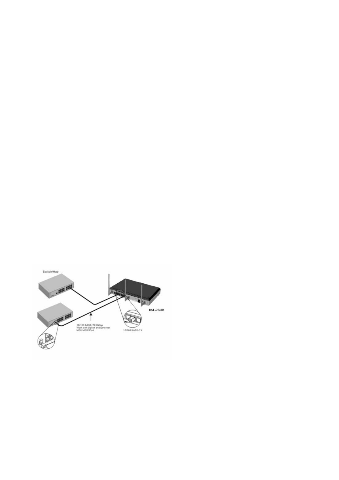
Hub or Switch to Router Connection
Connect the Router to an uplink port (MDI-II) on an Ethernet hub or switch with a straight-through cable as shown in
the diagram below:
If you wish to reserve the uplink
port on the switch or hub for
another device, connect to any on
the other MDI-X ports (1x, 2x, etc.)
with a crossed cable.
9
Page 20
DSL-2740B Wireless ADSL Router User Guide
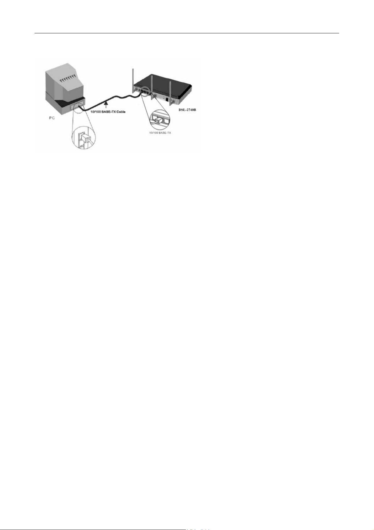
Computer to Router Connection
You can connect the Router
directly to a 10/100BASE-TX
Ethernet adapter card (NIC)
installed on a PC using the Ethernet
cable provided as shown in this
diagram.
10
Page 21
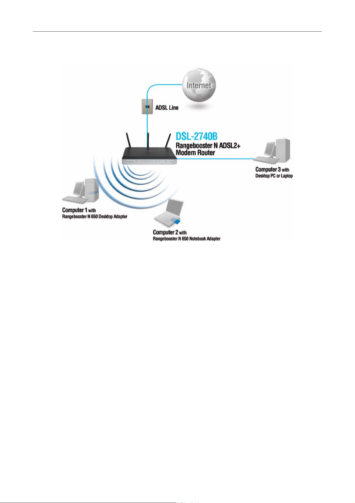
DSL-2740B Wireless ADSL Router User Guide
The illustration below shows the DSL-2740B connected to Ethernet LAN devices, Wireless LAN devices, and the
Internet.
11
Page 22
DSL-2740B Wireless ADSL Router User Guide
3
Basic Router Configuration
The first time you set up the Router it is recommended that you configure the ADSL (WAN) connection using a single
computer making sure that both the computer and the Router are not connected to the LAN. Once the WAN connection
is functioning properly, you may continue to make changes to Router configuration including IP settings and DHCP
setup. This chapter is concerned with using your computer to configure the WAN connection. The following chapter
describes the various windows used to configure and monitor the Router including how to change IP settings and DHCP
server setup.
Configuration Summary
1. Connect to the Router To configure the WAN connection used by the Router it is first necessary to
communicate with the Router through its management interface, which is HTML-based and can be accessed
using a web browser. To access the management software your computer must be able to “see” the Router.
Your computer can see the Router if it is in the same “neighborhood” or subnet as the Router. This is
accomplished by making sure your computer has IP settings that place it in the same subnet as the Router. The
easiest way to make sure your computer has the correct IP settings is to configure it to use the DHCP server in
the Router. The next section describes how to change the IP configuration for a computer running a Windows
operating system to be a DHCP client.
2. Configure the WAN Connection Once your are able to access the configuration software you can proceed to
change the settings required to establish the ADSL connection and connect to the service provider’s network.
There are different methods used to establish the connection to the service provider’s network and ultimately to
the Internet. You should know what Encapsulation and connection type you are required to use for your ADSL
service. It is also possible that you must change the PVC settings used for the ADSL connection. Your service
provider should provide all the information you need to configure the WAN connection.
Configuring IP Settings on Your Computer
In order to configure your system to receive IP settings from the Router your computer must first have the TCP/IP
protocol installed. If you have an Ethernet port on your computer, it probably already has TCP/IP protocol installed. If
you are using Windows XP the TCP/IP is enabled by default for standard installations. Instructions for configuring your
computer to receive IP settings from the Router are provided in Appendix B on page 98.
For computers running non-Windows operating systems, follow the instructions for your OS that configure the system
to receive an IP address from the Router, that is, configure the system to be a DHCP client.
If you are not sure how to configure your Windows computer to be a DHCP client, see
Note
Configuring IP Settings on Your Computer beginning on page 98.
12
Page 23
DSL-2740B Wireless ADSL Router User Guide
Access the Configuration Manager
In order to make sure your computer’s IP settings allow it to communicate with the Router, it is advisable to configure
your system be a DHCP client – that is, it will get IP settings from the Router. Appendix B describes how to configure
different Windows operating systems to “Obtain IP settings automatically”.
Be sure that the web browser on your computer is not configured to use a proxy server in the
Internet settings. In Windows Internet Explorer, you can check if a proxy server is enabled using the
following procedure:
1. In Windows, click on the Start button and choose Control Panel.
2. In the Control Panel window, click on the Network and Internet Options icon.
3. In the Network and Internet Connections window, click the Internet Options icon.
4. In the Internet Properties window, click on the Connections tab and click on the LAN Settings
Note
button
5. Verify that the “Use a proxy server for your LAN (These settings will not apply to dial-up or VPN
connections).” option is NOT checked. If it is checked, click in the checked box to deselect the
option and click OK.
Alternatively, you can access this Internet Options menu using the Tools pull-down menu in
Internet Explorer.
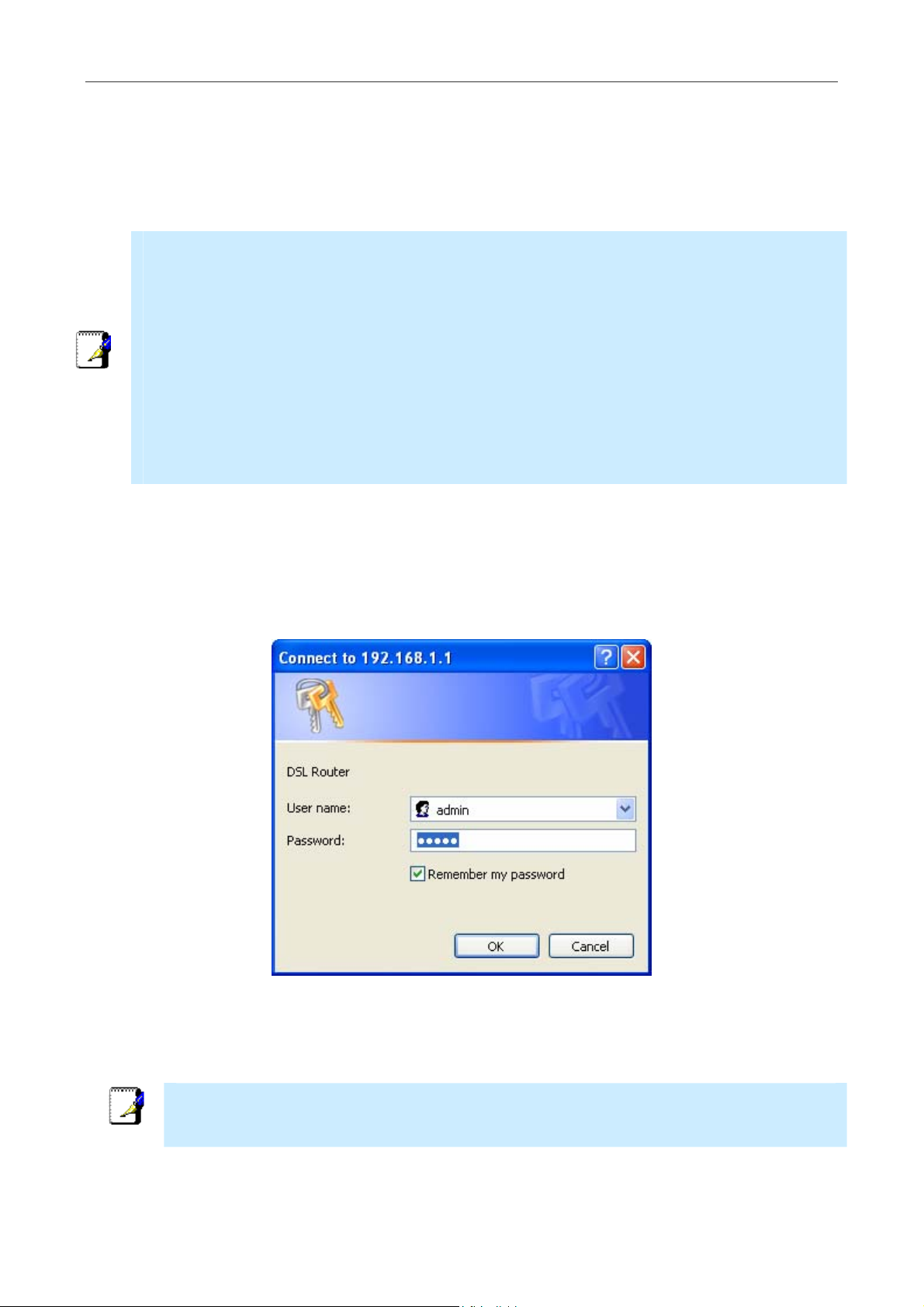
Login to Home Page
To use the web-based management software, launch a suitable web browser and direct it to the IP address of the Router.
Type in http:// followed by the default IP address, 192.168.1.1 in the address bar of the browser. The URL in the
address bar should read: http://192.168.1.1.
A dialog box prompts for the User Name and Password. Type in the default User Name “admin,” and the default
Password “admin” then click the OK button to access the web-based manager.
Enter Password
You should change the web-based manager access user name and password once you have verified that a connection
can be established. The user name and password allows any PC within the same subnet as the Router to access the webbased manger.
The user name and password used to access the web-based manager is NOT the same as the
ADSL account user name and password needed for PPPoE/PPPoA connections to access the
Note
Internet.
13
Page 24
DSL-2740B Wireless ADSL Router User Guide
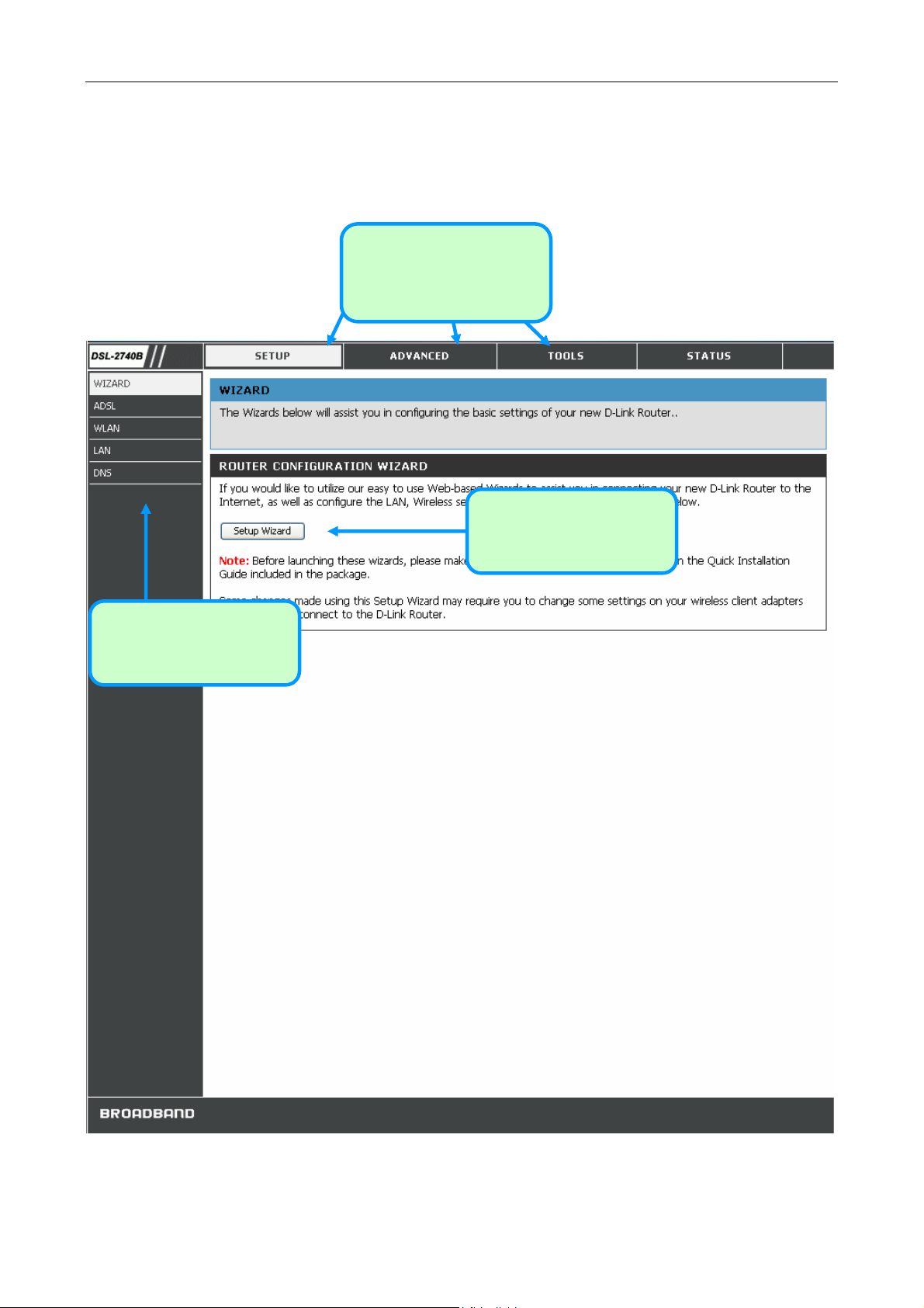
Configure the Router
When you successfully connect to the web manager, the Home directory tab will display the Setup Wizard window.
You can launch the Setup Wizard from this page or use the buttons located in the left panel of the web page to view
other windows used for basic configuration.
Click on a directory tab to
view the windows available
in that directory
Click the Setup Wizard
button to launch the Setup
Wizard
Click on a button to use or
view the window
Web Manager – First Time Log On
14
Page 25

DSL-2740B Wireless ADSL Router User Guide
All configuration and management of the Router is done using the web-based management interface pictured in the
above example. The configuration windows are accessed by clicking on the directory tabs: Home, Advanced, Tools,
and Status. Each tab has associated window buttons in the left hand panel of the web interface. Basic setup of the
Router can be completed in the windows accessed from the Home directory including: (Setup) Wizard, WLAN, WAN
(Internet), LAN (to configure the IP address of the Router), DNS and Dynamic DNS.
Wizard
To use the Setup Wizard, click the Setup Wizard button in the first browser window and follow the instructions.
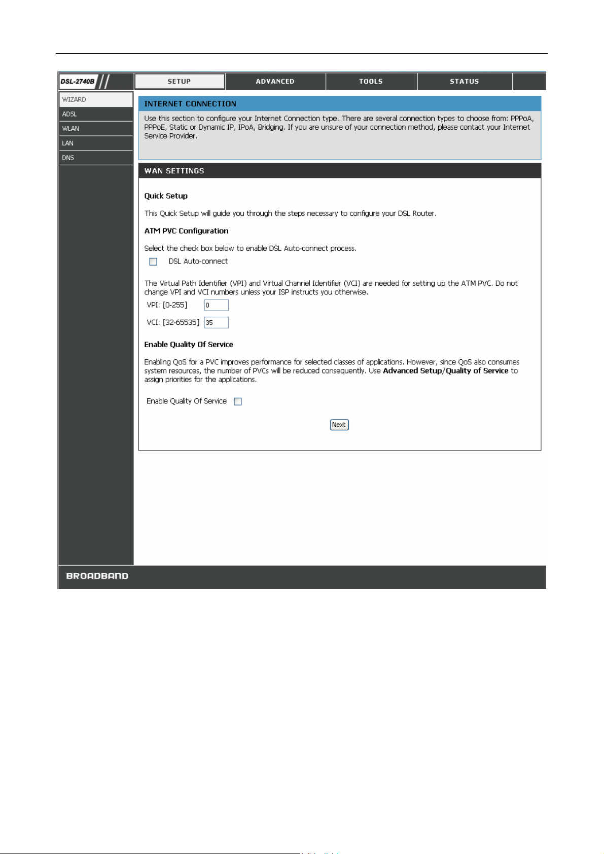
Using the Setup Wizard – WAN Settings – PVC Settings
First configure VPI and VCI for your ADSL connection. Your ISP has given this information to you. Or select DSL
Auto-connect and allow router to detect the available VPI/VCI for you. You can also enable QoS (Quality of Service)
by checking Enable Quality Of Service.
15
Page 26
DSL-2740B Wireless ADSL Router User Guide
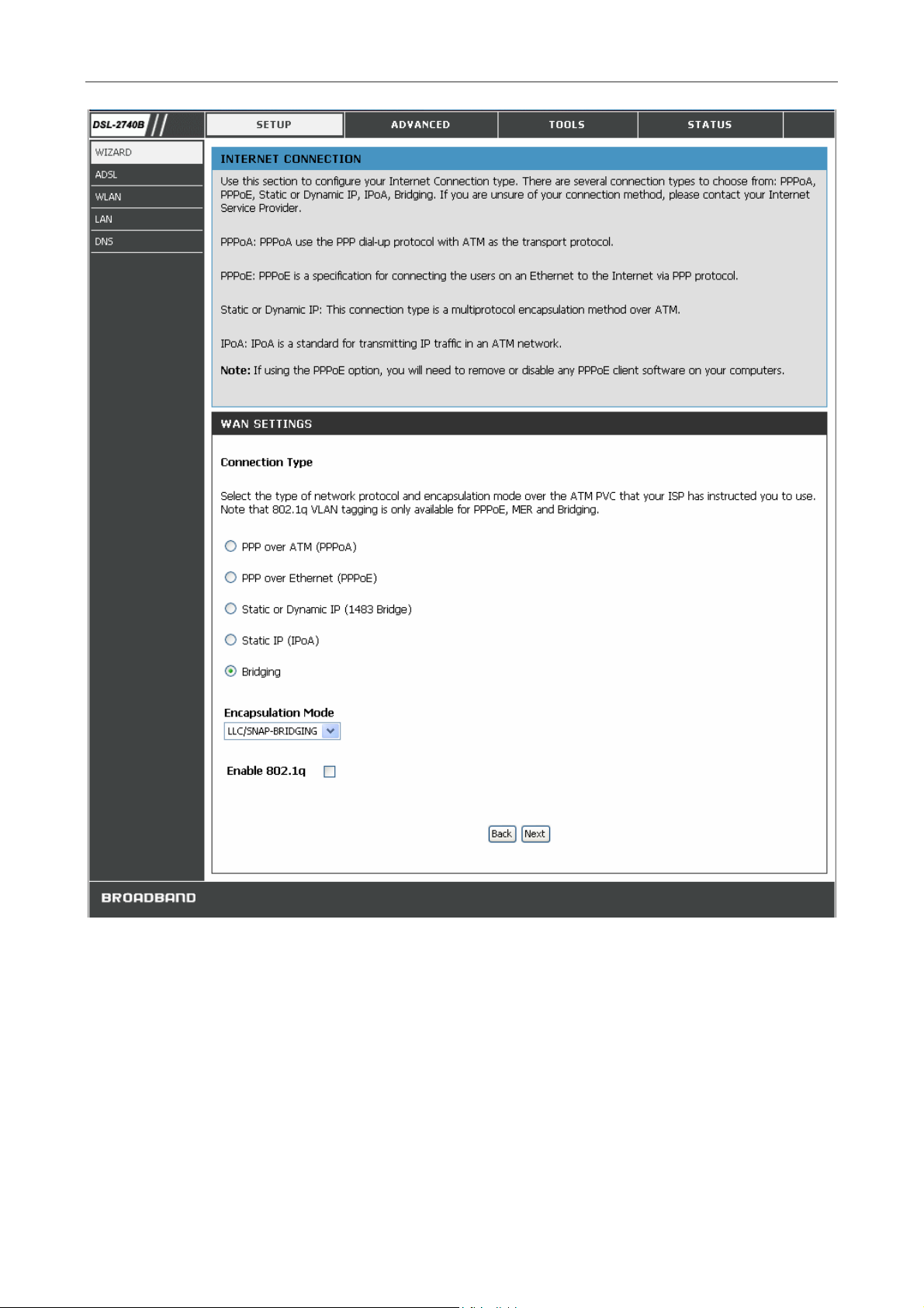
Click Next to go to the next Setup Wizard window.
Using the Setup Wizard – WAN Settings - Choose Connection Type
Now select the Connection Type used for the Internet connection. Your ISP has given this information to you. The
connection types available are PPPoA, PPPoE, MER, IPoA and Bridge Mode. The Encapsulation Mode includes
LLC/SNAP-BRIDGING and VC/MUX. Each connection type has different settings that are configured in the next
Setup Wizard window.
16
Page 27
DSL-2740B Wireless ADSL Router User Guide
17
Page 28
DSL-2740B Wireless ADSL Router User Guide
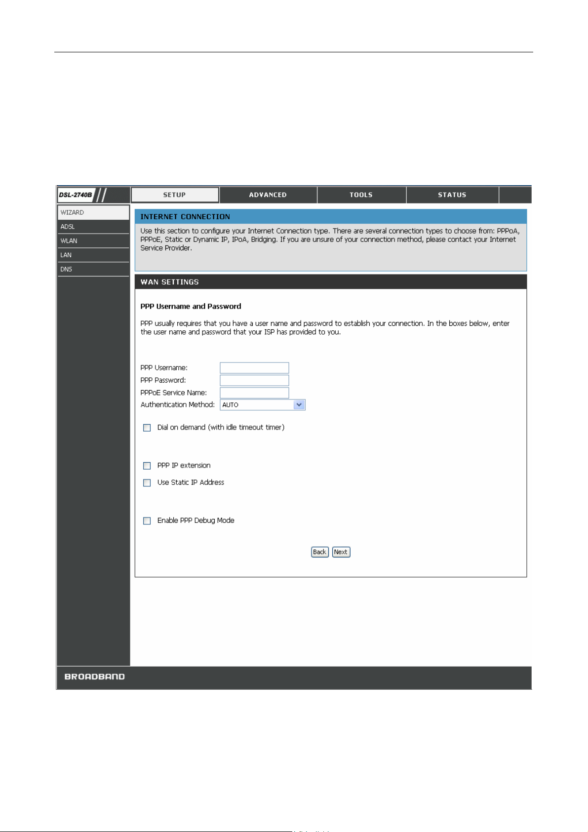
Using the Setup Wizard - For PPPoE/PPPoA connection:
1. Select the specific Connection Type and Encapsulation Mode.
2. Type in the Username and Password (and PPPoE Service Name, if required by your ISP) used to identify
and verify your account to the ISP.
3. Select the specific Authentication Method from the drop-down menu (PAP or CHAP). Or user default
AUTO to allow Router to negotiate with PPP server automatically.
4. Click Next to go to the next Setup Wizard window.
18
Page 29

DSL-2740B Wireless ADSL Router User Guide
Additional configurations available for PPP connection:
PPP Connection
Parameters
Dial on demand
PPP IP extension
Use Static IP Address
Enable PPP Debug Mode
Description
The Dial on demand function, if checked, will tear down the PPP link
automatically when there is no incoming/outgoing packet via WAN interface
for the programmed period of time that is set below (in minutes). Router
activates PPPoE connection automatically when user wants to access
Internet and there is no active PPPoE connection.
Router passes the obtained IP address to the local PC and acts as a bridge
only modem.
Type in the IP address given by your ISP in this field if your Router’s IP
address is not dynamically assigned.
Enable PPP debug mode so you can see the PPP authentication process
from Router Status Æ System Log.
19
Page 30
DSL-2740B Wireless ADSL Router User Guide
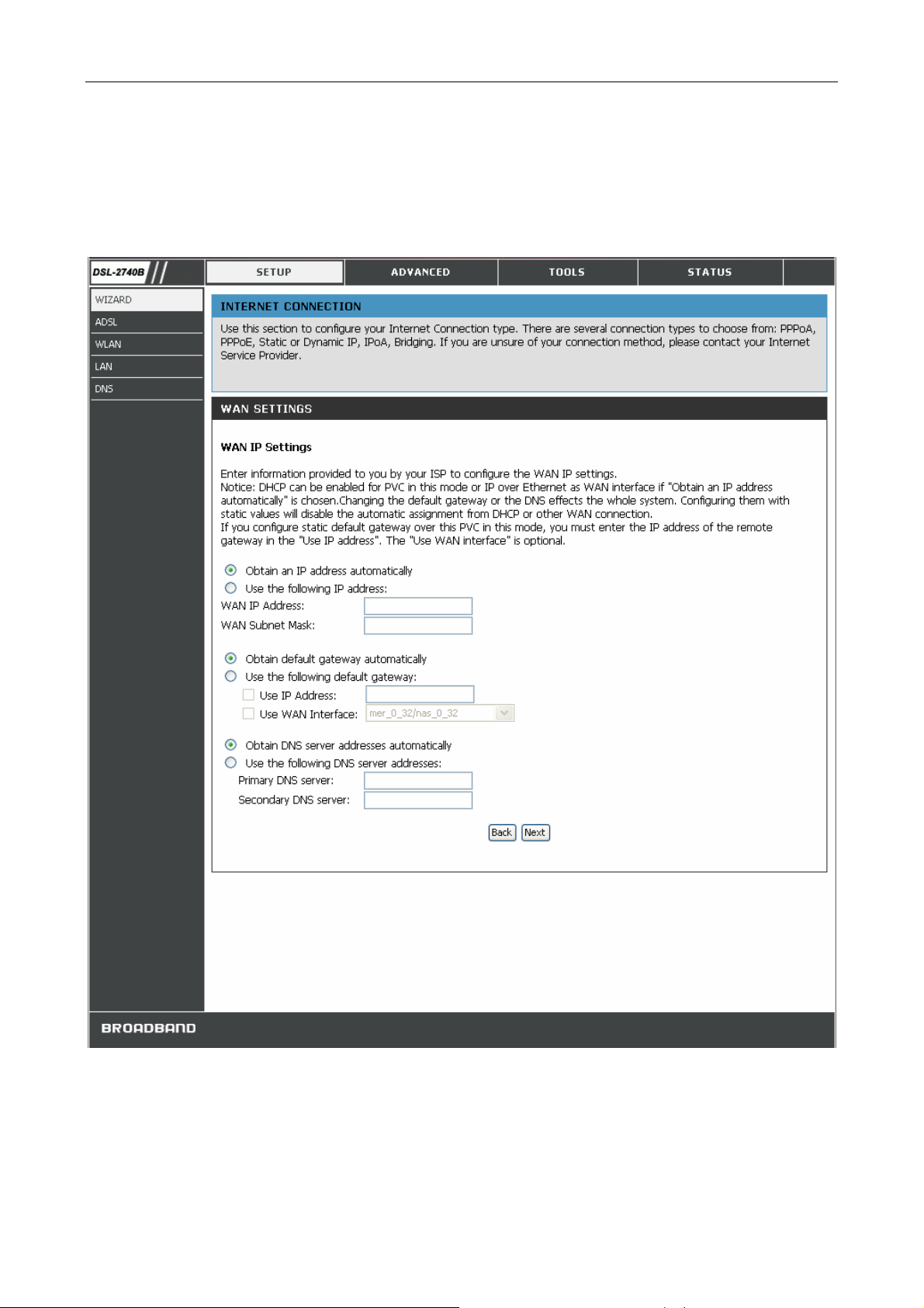
Using the Setup Wizard - For Dynamic IP (1483 Bridge) connection:
1. Select the specific Connection Type and Encapsulation Mode.
2. Select Obtain an IP address/Default gateway/DNS server automatically.
3. Click Next to go to the next Setup Wizard window.
20
Page 31

DSL-2740B Wireless ADSL Router User Guide
Using the Setup Wizard - For Static IP Address (1483 Bridge) connection:
1. Select the specific Connection Type and Encapsulation Mode.
2. Enter the WAN IP Address, WAN Subnet Mask provided by your ISP.
3. Select Use the following default gateway/DNS server addresses and enter the ISP Gateway Address,
Primary DNS Address, and Secondary DNS Server IP Address as instructed by your ISP.
4. Click Next to go to the next Setup Wizard window.
21
Page 32

DSL-2740B Wireless ADSL Router User Guide
Using the Setup Wizard - For Static IP Address (IPoA) connection:
5. Select the specific Connection Type and Encapsulation Mode.
6. Enter the WAN IP Address, WAN Subnet Mask provided by your ISP.
7. Select Use the following default gateway/DNS server addresses and enter the ISP Gateway Address,
Primary and Secondary DNS Server IP Address as instructed by your ISP.
8. Click Next to go to the next Setup Wizard window.
22
Page 33

DSL-2740B Wireless ADSL Router User Guide
Using the Setup Wizard - For Bridge Mode connections:
1. Select the specific Connection Type and Encapsulation Mode.
2. Click Next to go to the next Setup Wizard window.
Using the Setup Wizard - For WAN Connection Settings:
1. Select the specific functions to be enabled.
2. Click Next to go to the next Setup Wizard window.
23
Page 34

DSL-2740B Wireless ADSL Router User Guide
Using the Setup Wizard - For LAN Settings:
You can configure the LAN IP address to suit your preference. Many users will find it convenient to use the default
settings together with DHCP service to manage the IP settings for their private network. The IP address of the Router is
the base address used for DHCP. In order to use the Router for DHCP on your LAN, the IP address pool used for DHCP
must be compatible with the IP address of the Router. The IP addresses available in the DHCP IP address pool will
change automatically if you change the IP address of the Router.
1. Enter the desired IP address and Subnet Mask.
2. Enter the Start and Stop IP Address for the DHCP Server, or disable DHCP Server.
3. Click Next to go to the next Setup Wizard window.
24
Page 35

DSL-2740B Wireless ADSL Router User Guide
Using the Setup Wizard - For Wireless LAN Settings:
1. Click the Enable Wireless box to allow the router to operate in the wireless environment.
2. The SSID identifies members of the Service Set. Accept the default name or change it to something else. If
the default SSID is changed, all other devices on the wireless network must use the same SSID.
3. Click Next to go to the next window and complete the Setup Wizard.
25
Page 36

DSL-2740B Wireless ADSL Router User Guide
Using the Setup Wizard - Finish and Restart
Finally you can confirm that the setup process is completed. If you are satisfied that you have entered all the necessary
information correctly, click the Save/Reboot button to save the new configuration settings and restart the Router. If you
need to change settings from a previous window, click the Back button.
Do not turn the Router off while it is restarting. After the Router is finished restarting, you are now ready to continue
to configure the Router as desired. You may want to test the WAN connection by accessing the Internet with your
browser.
26
Page 37

DSL-2740B Wireless ADSL Router User Guide
ADSL
To access the ADSL (WAN) Settings window, click on the ADSL link button on the left side of the first window that
appears when you successfully access the web manager.
You can add, remove and edit the WAN interface from this page:
To add a WAN connection, click the Add button and follow the step-by-step instruction as in WIZARD.
To delete a WAN connection, select the specific Remove box and then click Remove button.
To edit a WAN connection, click the specific WAN interface Edit button and follow the step-by-step instruction as in
WIZARD.
Click the Save/Reboot button to apply your settings.
27
Page 38

DSL-2740B Wireless ADSL Router User Guide
ADSL Settings Window
Additional information for you to help you configure your WAN connections:
ATM Settings:
The ATM settings in the ADSL Settings windows for the different connection types can be used to adjust QoS
parameters for ADSL clients. This may not be available to all ADSL accounts.
ATM Parameters Description
The Router supports using up to eight multiple virtual connections. This
window allows the user to configure WAN settings for all the available
connections (see instructions below on how to set up Multiple Virtual
PVC
Connections). Use the PVC drop-down menu to select the connection (Pvc0
to Pvc7) you want to configure. Since most users will use only a single
Pvc0
connection, the default setting
the WAN settings.
can be used for any changes made to
VPI
VCI
Virtual Circuit
Service Category
The Virtual Path Identifier is used with the VCI to define a dedicated circuit
on the ATM network portion of the connection to the Internet and WAN.
Most users will not need to change this setting.
The Virtual Channel Identifier is used with the VPI to define a dedicated
circuit on the ATM network portion of the connection to the Internet and
WAN. Most users will not need to change this setting.
As with the PVC setting, this is mainly for use by clients who are configuring
the Router for multiple virtual connections. Use this to enable or disable the
PVC you are currently configuring. By default, the Pvc0 is
remaining PVCs are disabled.
The ATM settings allow the user to adjust ATM Quality of Service (QoS) or
traffic parameters to suit specific traffic requirements. For applications or
circumstances where packet loss or packet delay is a concern, ATM QoS can
be adjusted to minimize problems. For most accounts, it will not be
necessary to change these settings. Altering QoS settings can adversely
affect performance of some commonly used Internet applications.
If you plan to change QoS or traffic parameters, contact your ISP or
network services provider for information on what types of adjustment are
available or possible for your account. Your ISP may not support the class
of service you want to use.
To adjust ATM QoS parameters, select one of the Service Categories listed
here and type in the PCR value in the entry field below. For the VBR service
category, an additional parameter (SCR) must also be defined.
UBR
– Unspecified Bit Rate, this is the default category used for generalpurpose Internet traffic where normal levels of packet loss and delay are
acceptable. For some applications or for multiple connection accounts, it
may be desirable to specify the PCR.
CBR
– Constant Bit Rate, usually used in circumstances where very low
packet loss and very low Cell Delay Variable (CDV) are desirable.
VBR
– Variable Bit Rate, usually used when network traffic is characterized
Enabled
and the
28
Page 39

PCR
SCR
CDVT
MBS
DSL-2740B Wireless ADSL Router User Guide
by bursts of packets at variable intervals, and some moderate packet loss
and delay is acceptable. This category is typically used for audio and video
applications such as teleconferencing. The network must support QoS Class
2 to use VBR.
Peak Cell Rate – The PCR is inversely related to the time interval between
ATM cells. It is specified for all three service categories (UBR, CBR and
VBR) in Kbps.
Sustainable Cell Rate – The SCR is defined for the VBR service category.
This is the rate that can be sustained for “bursty”, on-off traffic sources. It
is a function of Maximum Burst Size (MBS) and the time interval (between
cells).
Cell Delay Variation Tolerance – CDVT is a measure of the cell clumping
phenomenon by which cells are delayed in the network and are
clumped together and arrive at a system at a faster rate than negotiated.
Increasing the CDVT creates greater bucket depth.
Maximum Burst Size – The MBS is the maximum number of bytes that can
be sent continuously from the source to the destination dropping any
packets. Some ATM providers set the MBS and CDVT very low and adjust
up if problems occur.
Router Settings:
Parameters Description
Default Route When this is enabled, the Router will be considered to be the primary
gateway to the Internet and WAN for systems on your network. If you
are using the Router on a network with one or more alternative gateway
routers, you may prefer to disable this if you will use another router as
the primary gateway.
NAT Network Address Translation may be enabled or disabled with the pull-
down menu. Keep in mind that disabling NAT allows only a single
computer to be used for Internet access through the Router. NAT is
enabled and disabled for the Router on all connections (i.e. Pvc0 – Pvc7)
if your Router is set up for multiple virtual connections.
Firewall Use this to universally enable or disable the Firewall and Filter features
available in the Router. If you disable this you will not be able to
configure settings in the Firewall Configuration window or Filters
window in the Advanced directory.
Primary DNS Address This is the IP address of the first choice for Domain Name Service (DNS)
used to match the named URL web address used by most browsers with
the actual global IP address used for a web server. Usually this will be a
server owned by the ISP. Get this IP address from your ISP.
Secondary DNS Address This is the second choice for a DNS server. Get this IP address from
your ISP.
29
Page 40

DSL-2740B Wireless ADSL Router User Guide
WLAN
To access the WLAN Settings window, click on the WLAN link button on the left side of the first window that appears
when you successfully access the web manager.
WLAN Settings Window
Click the Enable Wireless box to allow the router to operate in the wireless environment.
Click the Hide Access Point box to allow the router to stop broadcasting its SSID.
30
Page 41

DSL-2740B Wireless ADSL Router User Guide
The SSID identifies members of the Service Set. Accept the default name or change it to something else. If the default
SSID is changed, all other devices on the wireless network must use the same SSID.
Select your region form the Country drop down list. Operating channels are different for different country/region based
on regulation.
Please go to Advanced section for more wireless settings.
LAN
You can configure the LAN IP address to suit your preference. Many users will find it convenient to use the default
settings together with DHCP service to manage the IP settings for their private network. The IP address of the Router is
the base address used for DHCP. In order to use the Router for DHCP on your LAN, the IP address pool used for DHCP
must be compatible with the IP address of the Router. The IP addresses available in the DHCP IP address pool will
change automatically if you change the IP address of the Router.
To access the LAN setting window, click the LAN button in the Setup directory.
31
Page 42

DSL-2740B Wireless ADSL Router User Guide
LAN Settings Window
To change the LAN IP Address or Subnet Mask, type in the desired values and click the Save Settings button. You
will be asked to reboot by a pop-up window. Click OK to reboot the router.
You might need to re-configure your PC NIC seetings to enter the Router’s web manager after reboot.
32
Page 43

DSL-2740B Wireless ADSL Router User Guide
Parameters Description
UPnP UPnP supports zero-configuration networking and automatic discovery
for many types of networked devices. When enabled, it allows other
devices that support UPnP to dynamically join a network, obtain an IP
address, convey its capabilities, and learn about the presence and
capabilities of other devices. DHCP and DNS service can also be used if
available on the network. UPnP also allows supported devices to leave a
network automatically without adverse effects to the device or other
devices on the network.
IGMP Snooping IGMP snooping is a feature that allows the layer-2 device (switch) to
"listen in" on the IGMP conversation between hosts and routers. By
doing so, this device can forwards the multicast packets to the hosts
which have joined the multicast group, instead of flooding to all hosts.
Standard Mode: Listen and forward
Blocking Mode: Listen and block
DHCP The DHCP server is enabled by default for the Router’s Ethernet LAN
interface. DHCP service will supply IP settings to workstations configured
to automatically obtain IP settings that are connected to the Router
though the Ethernet port. When the Router is used for DHCP it becomes
the default gateway for DHCP client connected to it. Keep in mind that if
you change the IP address of the Router the range of IP addresses in
the pool used for DHCP on the LAN will also be changed. The IP address
pool can be up to 253 IP addresses.
Note
To manually configure IP settings on
Windows workstations, open the
TCP/IP Properties menu and select
the “Use the following IP address”
option. You will need to supply the
IP addres, Subnet mask and Defualt
gateway (use IP address of DSL2740B) for each workstation. The
example here also uses manually
configured DNS settings.
33
Page 44

DNS
The Router can be configured to relay DNS settings from your ISP or another available service to workstations on your
LAN. When using DNS relay, the Router will accept DNS requests from hosts on the LAN and forward them to the
ISP’s, or alternative DNS servers. DNS relay can use auto discovery or the DNS IP address can be manually entered by
the user. Alternatively, you may also disable the DNS relay and configure hosts on your LAN to use DNS servers
directly. Most users who are using the Router for DHCP service on the LAN and are using DNS servers on the ISP’s
network, should check Enable Automatic Assigned DNS box.
DNS Configuration window
If you have DNS IP addresses provided by your ISP, enter these IP addresses in the available entry fields for the
Primary DNS Server and the Secondary DNS Server.
34
Page 45

When you have configured the DNS settings as desired, click the Save Settings button.
35
Page 46

Advanced Router Management
4
This chapter introduces and describes
the management features that have
not been presented in the previous
chapter. These include the more
advanced features used for network
management and security as well as
administrative tools to manage the
Router, view statistics and other
information used to examine
performance and for troubleshooting.
Use your mouse to click the directory
tabs and window buttons in order to
display the various configuration and
read-only windows discussed below.
The table below summarizes again the
directories and menus available in the
management web interface. In this
chapter you will find descriptions for
the windows located in the Advanced,
Tools and Status directories.
Directory Configuration and Read-only Windows
Click the Setup tab to access the Wizard, ADSL Settings, WLAN Settings,
Setup
Advanced
Tools
Status
36
LAN Settings, and DNS Setup. See the previous chapter for a description of
the Setup directory windows.
Click the Advanced tab to access the Advanced ADSL, Advanced WLAN,
WLAN Security, WLAN Filter, WLAN Bridge, WLAN QoS, Firewall Settings,
Virtual Server, Port Trigering, DMZ, Outgoing/Incoming IP Filter, Bridge
Filter, Parent Control, URL Filter, Quality Of Service, Routing, RIP, and Port
Mapping.
Click the Tools tab to access the Diagnostics, Backup Settings, Update
Settings, Restore Default, TR069 Client, SNMP Configuration, DDNS, Time,
Access Service, Access IP, Password, Update Firmware, and Save/Reboot.
Click the Status tab to view the Device Information, ADSL, LAN, WAN, ATM,
Page 47

Route, ARP, DHCP Clients, WLAN Station, and System Log.
ADVANCED ADSL
The ADSL Configuration window allows the user to set the configuration for ADSL protocols. For most ADSL
accounts the default settings (ADSL2+) will work. This configuration works with all ADSL implementations. Do not
change any settings unless you have been instructed. To make ADSL settings, select the desired items and click the
Save Settings button.
ADVANCED ADSL Window
37
Page 48

ADVANCED WLAN
ADVANCED WLAN page allows you to tweek more advanced wireless settings. Most users will do just fine using
default settings.
ADVANCED WLAN Window
Configure these parameters for your router:
WLAN Parameters Description
AP Isolation
38
This is used to islolate wireless clients which connect to different APs.
Page 49

Channel
802.11 Mode
Bandwidth
802.11n Rate
Fragmentation Threshold
RTS Threshold
DTIM Interval
Beacon Interval
Preamble Type
Transmit Power
Operation channel of your access point. Channel availability is different for
different countries due to their regulation.
Select Mixed 802.11ng and 802.11b to operate in b/g/n mode. Or
select specified mode to use.
Channel bandwidth. Maximum rate for 20 MHz is 130 Mbps. Maximum
rate for 40 MHz is 270 Mbps.
Select Auto to operate in all available transmission rates. Or select
specified rate to use.
Maximum frame size. Frame larger than the threshold are fragmented into
multiple packets and transmitted. The range is 256~2346 bytes.
If a network packet is smaller than the preset RTS threshold size, the
RTS/CTS mechanism will not be enabled. The router sends Request to
Send (RTS) frames to a particular receiving station and negotiates the
sending of a data frame. After receiving an RTS, the wireless station
responds with a Clear to Send (CTS) frame to acknowledge the right to
begin transmission.
The range is 0~2347 bytes.
Interval of the Delivery Traffic Indication Message (DTIM). A DTIM field is
a countdown field informing clients of the next window for listening to
broadcast and multicast messages. When the router has buffered
broadcast or multicast for associated clients, it sends the next DTIM with a
DTIM Interval value. Its clients hear the beacons and awaken to receive
the broadcast and multicast message. The range is 1~255 milliseconds,
The Beacon Interval value indicates the frequency interval of the
beacon. A beacon is a packet broadcast by the router to synchronize the
wireless network. The value is 1~65535 milliseconds.
The preamble is used to synchronize the transmitter and receiver and
derives common timing releationship. The Short preamble improves
throughput but not all wireless clients support short preamble type.
5-level of transmit power are available: 20%, 40%, 60%, 80%, and
100%.
WLAN SECURITY
In the WLAN Security window, select the type of security you want to configure. The window will change to present
the settings specific to the method being configured. The Router’s wireless security options include WEP, 802.1x, WPA,
WPA-PSK(Pre- Shared Key), WPA2, WPA2-PSK, Mixed WPA/WPA2, Mixed WPA/WPA2-PSK.
WEP
WEP (Wireless Encryption Protocol) encryption can be enabled for security and privacy. WEP encrypts the data
portion of each frame transmitted from the wireless adapter using one of the predefined keys. The router offers 64-, or
128-bit encryption with four keys available.
1. Select Network Authentication type from the drop-down list. (Shared is bettern than Open)
2. Select Encryption Strength from the drop-down list. (128-bit is stronger than 64-bit)
3. Specify the encryption key from the Current Network Key drop-down list.
4. Enter the key into the Network Key field 1~4. (Key length is outlined at the bottom of the window.)
39
Page 50

5. Click the Save Settings button to apply settings.
WLAN SECURITY Window – WEP
Notice If encryption of any kind, at any level is applied to the Router, all devices on the
network must comply with all security measures.
802.1x
Some network-security experts now recommend that wireless networks use 802.1X security measures to overcome
some weaknesses in standard WEP applications. A RADIUS server is used to authenticate all potential users.
40
Page 51

1. Select 802.1x from the Network Authentication drop-down list.
2. Enter your RADIUS server data: IP Address, Port, and Key.
3. Configure WEP Encryption. (See above section for detail.)
4. Click the Save Settings button to apply settings.
WLAN SECURITY Window – 802.1x
WPA-PSK
WPA-PSK configuration is similar to WEP. The key length is between 8 to 63 ASCII codes.
41
Page 52

WLAN Security Window – WPA-PSK
WPA (Wi-Fi Protected Access)
Wi-Fi Protected Access was designed to provide improved data encryption, perceived as weak in WEP, and to provide
user authentication, largely nonexistent in WEP.
To take full advanteage of WPA, a RADIUS server is needed in your network to authenticate users. For most home or
SOHO users, WPA-PSK is the easiest way to implement and provides adequate protection for your wireless network.
1. Select your wireless security method from the Network Authentication drop-down list.
2. Enter the RADIUS Server IP Address, Port, and Key.
3. Select the encryption method from WPA Encryption drop-down list.
42
Page 53

4. Click Save Settings to apply your settings.
WLAN Security Window – WPA
WLAN Filter
The WLAN Filter is used to control wireless client devices access based on their MAC addresses. You can choose to
allow or deny the specific MAC addresses.
1. Click the Add button to enter WLAN Filter configuration window.
2. Enter the specific MAC address and click the Save Settings button to apply.
3. Click the MAC Restrict Mode radio button to select filter rule (Allow or Deny) and enable the WLAN filter.
43
Page 54

WLAN FILTER Window
WLAN BRIDGE
Wireless bridge is used to bridge AP traffic between other APs. You can select Wireless Bridge (also known as
Wireless Distribution System) to disables access point functionality. Selecting Access Point enables access point
functionality. Wireless bridge functionality will still be available and wireless stations will be able to associate to the
AP. Select Disabled in Bridge Restrict which disables wireless bridge restriction. Any wireless bridge will be granted
access. Selecting Enabled or Enabled (Scan) enables wireless bridge restriction. Only those bridges selected in Remote
Bridges will be granted access. Only APs operating in the same channel can be bridged together.
44
Page 55

Notice Wlreless Bridge function is available only when 802.11n is disabled. Please go to
ADVANCED WLAN page to disable 802.11n before configuring Wireless Bridge.
1. Select AP Mode from the drop-down list.
2. Select Enabled in Bridge Restrict drop-down list and enter the MAC address of the AP which to be bridged.
Or,
3. Select Enabled(Scan) in Bridge Restrict drop-down list and the Router starts to search and displays available
APs. Click the specific AP check box.
4. Click the Save Settings button to apply settings.
WLAN BRIDGE Window
45
Page 56

WLAN QOS
WLAN QoS (Quality of Service), also called WMM (Wi-Fi Multi-media), is used to prioritize the wireless packets
when you are using wireles device transmitting delay-sensitive packets (voice, video,..etc).
Notice WMM is not supported by IEEE 802.11n yet. You must trun off 802.11n in
ADVANCED WLAN section before configuring any WMM settings.
1. Select Enabled from the WMM(Wi-Fi Multimedia) drop-down list.
2. Select Disabled from the WMM No Acknowledgement drop-down list if your wireless link quality is good. It
can increase more bandwidth. Or select Disable if your link quality is an issue.
3. Click the Add QoS Entry button to enter QoS configuration window.
46
Page 57

WLAN QoS Window (1)
4. Enter the name of the rule.
5. Select priority from the Wireless Transmit Priority drop-down list (1~4, higher number has higher priority).
6. Specify traffic classification rules. The classification can be de fined in the following parameters: Protocol,
Source/Destination IP Address, and Source/Destination Port.
7. Click the Save Settings button to apply this rule.
8. Click the Save/Apply WME Settings button to apply settings.
47
Page 58

WLAN QoS Window (2)
FIREWALL
The Firewall Configuration window allows the Router to enforce specific predefined policies intended to protect
against certain common types of attacks. There are two general types of protection (DoS, Port Scan) that can be enabled
on the Router, as well as filtering for specific packet types sometimes used by hackers.
SPI (Stateful Packet Inspection) is a firewall feature that checks the state of network connections. Only legitimate
packets are allowed to passthrough.
A DoS (denial-of-service) attack is characterized by an explicit attempt by attackers to prevent legitimate users of a
service from using that service. Examples include: attempts to "flood" a network, thereby preventing legitimate network
48
Page 59

traffic, attempts to disrupt connections between two machines, thereby preventing access to a service, attempts to
prevent a particular individual from accessing a service, or, attempts to disrupt service to a specific system or person.
Port scan protection is designed to block attempts to discover vulnerable ports or services that might be exploited in an
attack from the WAN.
Select specific VPN type from the VPN Passthrough check-box if a VPN client is used behind the Router.
FIREWALL Window
49
Page 60

VIRTUAL SERVER
Use the Virtual Server window to set up single-port or static-port range forwarding rules applied to inbound (WAN-toLAN) traffic. The Virtual Server function allows remote users to access services on your LAN such as FTP for file
transfers or SMTP and POP3 for e-mail. The DSL-2740B will accept remote requests for these services at your Global
IP Address, using the specified TCP or UDP protocol and port number, and then redirect these requests to the server on
your LAN with the LAN IP address you specify. Remember that the specified Private IP Address must be within the
useable range of the subnet occupied by the Router.
UDP/TCP port redirection is used to direct inbound traffic to the specified servers or workstations on your private
network. Port redirection can also be used to direct potentially hazardous packets to a proxy server outside your firewall.
For example, you can configure the Router to direct HTTP packets to a designated HTTP server in the DMZ. You can
define a set of instructions for a specific incoming port or for a range of incoming ports. Each set of instructions or rule
is indexed and can be modified or deleted later as needed.
50
Page 61

VIRTUAL SERVER window
1. Click the Add A Rule button to enter your virtual server configuration window.
2. Select a service from the drop down list for pre-configured server or select Custom Server to define your own
server.
3. Enter your server IP address, protocol and port number.
4. Click Add Rules button to apply settings.
There are many different pre-configured rules available for specific functions such as Internet gaming, VPN, streaming
and interactive multi-media, standard TCP/IP protocols, reserved ports, p2p, network management applications, and so
on.
Configure these parameters for virtual server on the router:
Virtual Server Category
Description
Server IP Address IP address of your server
External Port Start/End Starting and Ending port number for remote users
Protocol Protocol used by your server
Internal Port Start/End Starting and Ending port number that the router will forward to (In most
cases, they are the same as External port numbers)
PORT TRIGGERING
Some applications require that specific ports in the Router's firewall be opened for access by the remote parties. Port
Trigger dynamically opens up the 'Open Ports' in the firewall when an application on the LAN initiates a TCP/UDP
connection to a remote party using the 'Triggering Ports'. The Router allows the remote party from the WAN side to
establish new connections back to the application on the LAN side using the 'Open Ports'. A maximum 32 entries can be
configured.
1. Click the Add Rule button to enter your port triggering configuration window.
2. Select an application from the drop down list for pre-configured applicationr or select Custom Application to
define your own rules.
3. Enter your trigger/open port number(s), and trigger/open protocol.
4. Click Add A Rule button to apply settings.
51
Page 62

PORT TRIGGERING Window
Configure these parameters for port triggering on the router:
Virtual Server Category
Description
Trigger Port Start/End Triggered port number initiated by local host
Trigger Protocol Triggered protocol initiated by local host
Open Port Start/End Opened port number(s) for remote users
52
Page 63

Open Protocol Opened protocol for remote users
DMZ
Since some applications are not compatible with NAT, the Router supports use of a DMZ IP address for a single host on
the LAN. This IP address is not protected by NAT and will therefore be visible to agents on the Internet with the right
type of software. Keep in mind that any client PC in the DMZ will be exposed to various types of security risks. If you
use the DMZ, take measures (such as client-based virus protection) to protect the remaining client PCs on your LAN
from possible contamination through the DMZ.
DMZ Window
53
Page 64

To designate a DMZ IP address, type in the IP Address of the server or device on your LAN in the DMZ Host IP
Address box, and click the Save Settings button. To remove DMZ status from the designated IP address, clear the IP
address in the box and click the Save Settings button.
OUTGOING IP FILTER
By default, all outgoing packets are allowed. But you can block specific type of packets from local hosts to Internet by
setting up outgoing IP filter.
1. Click the Add A Rule button to enter your outgoing IP filter configuration window.
2. Enter the filter name and at least one of the following criteria: Protocol, Source/Destination IP Address, and
Source/Destination Port.
3. Click Add A Rules button to apply settings.
54
Page 65

OUTGOING IP FILTER Window
If more than one criterion is configured, all of them must be matched for this outgoing
Note
filter rule to take effect.
55
Page 66

INCOMING IP FILTER
By default, all incoming packets are blocked if Firewall is enabled. But you can allow specific type of packets to be
accepted by setting up incoming IP filter.
1. Click the Add A Rule button to enter your incoming IP filter configuration window.
2. Enter the filter name and at least one of the following criteria: Protocol, Source/Destination IP Address, and
Source/Destination Port.
3. Select WAN interface(s) to apply this rule.
4. Click Add A Rules button to apply settings.
56
Page 67

INCOMING IP FILTER Window
BRIDGE FILTER
Bridge filters are used to block or allow various types of packets through the WAN interface. This may be done for
security or to improve network efficiency. The rules are configured for individual devices based on MAC address. Filter
rules can be set up for source, destination or both. Bridge Filter is only effective on ATM PVCs configured in Bridge
mode. The Global Policy FORWARDED means that all MAC layer frames will be FORWARDED except those
matching with any of the specified rules in the following table. BLOCKED means that all MAC layer frames will be
BLOCKED except those matching with any of the specified rules in the following table.
57
Page 68

1. Click Chnage Policy button to change bridge filter policy between Forwarded and Blocked.
2. Click the Add A Rule button to enter your bridge filter configuration window.
3. Select Protocol Type from the drop-down list, or leave it blank for all protocols.
4. Enter the Destination/Source MAC address of the specific devices.
5. Select Frame Direction from the drop-down list. LANÙWAN: Both directions. WAN=>LAN: From WAN
to LAN only. LAN=>WAN: From LAN to WAN only.
6. Select the WAN interfaces (Bridge only).
7. Click Save Settings button to apply filter rule.
BRIDGE FILTER Window
58
Page 69

PARENT CONTROL
Parent control is used to prevent specific local hosts from accessing Internet based on their MAC address.
1. Click the Add A Rule button to enter your parent control configuration window.
2. Enter the user name and MAC address of the restricted PC.
3. Select days and enter time frame to apply this rule.
4. Click Save/Apply button to apply settings.
59
Page 70

PARENT CONTROL Window
Local host’s MAC address will be displayed automatically when enter this
Note
configuration page. To find out other PC’s MAC address. Open the specific PC’s
command prompt window, type command ipconfig /all and check Physical
Address row.
URL FILTER
URL filter is used to control Internet website access. You can decide that your local hosts can access these specific
websites only, or can not access these websites only.
1. Select from the drop-down list Turn on Website Filtering (Allow or Deny).
2. Enter the website URLs or keywords.
3. Click Save Settings to apply this rule
To turn off URL filter, select Turn Website Filtering OFF from drop-down list and click Save Settings.
60
Page 71

URL FILTER Window
QUALITY OF SERVICE
QoS (Quality of Service) is a traffic class rule to classify the upstream traffic, assign queuing priority and optionally
overwrite the IP header TOS byte. This is to ensure that the delay-sensitive traffic has higher priority to go to Internet.
IP Precedence and IP TOS (Type of Service) marking, once enabled, will overwrite the correspondent TOS byte in the
IP haeder. These features, along with Differentiated Service Configuration, are valid only when your ISP has implement
these services.
1. Click the Add button to enter your QoS configuration window.
61
Page 72

2. Enter the name of the rule.
3. Assign ATM priority from the Assign ATM Transmit Priority drop-down list.
4. Check Enable Differentiated Service Configuration box if it is supported by your ISP.
5. Select the optional marking on IP Precedence and TOS from the Mark IP Precedence and Mark IP Type Of
Service drop-down lists.
6. Specify traffic classification rules from SET-1. The classification can be de fined in the following parameters:
Physical LAN port, Protocol, Source/Destination IP Address, and Source/Destination Port.
7. Click Save Settings to apply this rule.
QUALITY OF SERVICE Window
62
Page 73

All of the specified conditions in this classification rule must be satisfied for the rule to take effect.
To delete the configured QoS rule, check the box in Remove field and click Remove button on top.
ROUTING
Use Static Routing to specify a route used for data traffic within your Ethernet LAN or to route data on the WAN. This
is used to specify that all packets destined for a particular network or subnet use a predetermined gateway.
1. Click the Add button to enter your routing configuration window.
2. Enter the Destination Network Address, Subnet Mask, Gateway IP Address, and/or available WAN
Interface.
3. Click Save Settings to apply this rule.
63
Page 74

ROUTING Window
RIP
The Router supports RIP v1 and RIP v2 used to share routing tables with other Layer 3 routing devices on your local
network or remote LAN.
1. Click the Enabled radio button to enable the router RIP function.
2. Select RIP Version and Operation mode from the drop-down list.
64
Page 75

3. Check Enabled box and click Save Settings to apply your settings.
To disable RIP, click Disabled radio button and click Save Settings.
More on RIP settings:
RIP Parameters Description
65
RIP Window
Page 76

Interface The interface which RIP function is applied.
Version RIP has two versions available: RIP 1 and RIP 2. RIP 1 uses classed
routing table and RIP 2 uses classless routing table.
Operation Two operation modes are available: Active and Passive.
Active mode: Router listens and shares routing table with other devices.
Passive mode: Router only listens and updates its own routing tables.
PORT MAPPING
Port Mapping supports multiple ports to PVC and bridging groups. Each group will perform as an independent network.
To support this feature, you must create mapping groups with appropriate LAN and WAN interfaces. By default, all
interfaces are included in the Default group. And only the Default group has IP interface to access Router ‘s
configuration window. The interfaces which have been selected to form a mapping group will no longer have the ability
to access the router configuration window.
1. First, select Enable virtual ports on box to enable port mapping.
66
Page 77

PORT MAPPING Window (1)
2. Click Add button to enter port mapping configuration window.
3. Enter the group name and select the specific interfaces from Available Interfaces (Default group) to Grouped
Interfaces.
4. Click Save Settings to apply your settings.
67
Page 78

PORT MAPPING Window (2)
68
Page 79

TOOLS
Click the Tools tab to reveal the window buttons for various functions located in this directory. The Diagnostics
window is the first item in the Tools directory. The Diagnostic Test window is used to test connectivity of the Router.
A Ping test may be done through the local or external interface to test connectivity to known IP addresses. The
diagnostics feature executes a series of test of your system software and hardware connections. Use this window when
working with your ISP to troubleshoot problems.
DIAGNOSTICS Window
69
Page 80

BACKUP SETTINGS
Once you have configured the Router to your satisfaction, it is a good idea to back up the configuration file to your
computer. To save the current configuration settings to your computer, click the Backup Settings button in the Tools
directory to display the window. Click the Backup Settings button to Save Settings to Local Hard Drive. You will be
prompted to select a location on your computer to put the file. The configuration file may be named anything you like.
BACKUP SETTINGS window
70
Page 81

UPDATE SETTINGS
To load a previously saved configuration file, click the Browse button and locate the file on your computer. Click the
Update Settings button to load settings from local hard drive. Confirm that you want to load the file when prompted
and the process is completed automatically. The Router will reboot and begin operating with the configuration settings
that have just been loaded.
UPDATE SETTINGS Window
RESTORE DEFAULT
To reset the Router to its factory default settings, click the Restore button. You will be prompted to confirm your
decision to reset the Router. The Router will reboot with the factory default settings including IP settings (192.168.1.1)
and Administrator password (admin).
71
Page 82

RESTORE DEFAULT Window
TR069 CLIENT
TR-069 is a WAN Management Protocol which allows an Auto-Configuration Server (ACS) to perform autoconfiguration, provision, collection, and diagnostics to this device. You should have all the necessary information frm
your ISP if TR-069 is implemented by your ISP.
1. Click Enable radio button to enable TR-069.
2. Enter your ACS server data and user name/password.
72
Page 83

3. Click Save/Apply to apply your settings.
TR-069 CLIENT Window
SNMP CONFIGURATION
Simple Network Management Protocol is a standard for internetwork and intranetwork management. Please contact
your ISP for all necessary information before configuring SNMP.
1. Click Enable radio button in SNMP Agent.
2. Enter all data provided by your ISP.
73
Page 84

3. Click Save/Apply to apply your settings.
SNMP CONFIGURATION Window
DDNS
The Router supports DDNS (Dynamic Domain Name Service). The Dynamic DNS service allows a dynamic public IP
address to be associated with a static host name in any of the many domains, allowing access to a specified host from
various locations on the Internet. This is enabled to allow remote access to a host by clicking a hyperlinked URL in the
form hostname.dyndns.org, Many ISPs assign public IP addresses using DHCP, and this can make it difficult to locate a
74
Page 85

specific host on the LAN using standard DNS. If for example you are running a public web server or VPN server on
your LAN, this ensures that the host can be located from the Internet if the public IP address changes. DDNS requires
that an account be setup with one of the supported DDNS service providers (DyndDNS.org or TZO).
1. Click the Add button to enter your DDNS configuration window.
2. Select DDNS service provider from the D-DNS provider drop-down list and enter your account data.
3. Click Save/Apply button to apply settings.
Notice DDNS requires that an account be setup with one of the supported DDNS service
provider prior to engaging it on the router. This function will not work without an accepted
account with a DDNS service provider.
75
DDNS Window
Page 86

Configure these parameters for DDNS:
DDNS Parameters Description
DDNS Server Select one of the DDNS registration organizations form those listed in the
pull-down menu. Available servers include DynDns.org and TZO.
Host Name Enter the host name of your server.
Interface Select your WAN interface (if more than one) that DDNS is applied to.
Username (or Key) Enter the username given to you by your DDNS service provider.
Password (or Key) Enter the password or key given to you by your DDNS service provider.
Email (if used) Enter the email address registered to your DDNS service provider.
TIME
The Router provides you a method (Network Time Protocol) to maintain your router system clock via Internet.
1. Select Automatically synchronize with Internet time servers.
2. Select specific time server to use from the First NTP time server drop-down list; or you can select Other
from the drop-down list and type the preferable time server in the right field.
3. Configure the Second NTP time server for backup purpose.
4. Select your operating time zone from Tine zone offset drop-down list.
5. Click Save/Apply to apply your settings.
76
Page 87

TIME Window
ACCESS SERVICE
You can select to enable or disable of which management services from being used in your router, for LAN and/or
WAN interface. You need configure at least one WAN interface (except Bridge) before settings up service control list
on WAN interface. Access Service is not available for Bridge mode.
1. Select the management services which you want to enable/disable on your LAN/WAN interface.
77
Page 88

2. Click the Save/Apply button to apply your settings.
CAUTION: If you disable HTTP service, you’ll not be able to access the router’s
configuration window permanently.
ACCESS SERVICE Window
78
Page 89

ACCESS IP
The IP Address Access Control mode, if enabled, permits access to local management services from IP addresses
contained in the Access Control List. The available management services are configured in the Access Service.
1. Click Add button to enter access IP address configuration window.
2. Enter the specific IP address which will be granted access and click Save/Apply button.
3. After adding all IP addresses, click Enable radio button to enable IP access control.
To remove configured IP address, select Remove box of the specific entry and click Remove button.
79
Page 90

ACCESS IP Window
PASSWORD
Access to your router is controlled through three user accounts: admin, support, and user. The user name admin has
unrestricted access to change and view configuration of your router. The user name support is used to allow an ISP
technician to access your router for maintenance and to run diagnostics. The user name user can access the router, view
configuration settings and statistics, as well as, update the router's software. By default, all passwords are the same as
their account name. To change password, select the specific account and enter the old/new password. Click the
Save/Apply button to apply settings.
PASSWORD Window
80
Page 91

UPDATE FIRMWARE
Use the Firmware Upgrade window to load the latest firmware for the device. Note that the device configuration
settings may return to the factory default settings, so make sure you save the configuration settings with the System
Settings window described above.
To upgrade firmware, click on the Browse button to search for the file. Click the Update Firmware button to begin
copying the file. The Router will load the file and restart automatically.
UPDATE FIRMWARE Window
Note
Performing a Firmware Upgrade can sometimes change the configuration settings. Be
sure to back-up the Router’s configuration settings before upgrading the firmware.
SAVE / REBOOTt
Click the Save/Reboot button to save the previously made configurations and reboot the router.
81
Page 92

SAVE / REBOOT Window
82
Page 93

STATUS
Use these windows to view system information and monitor performance.
DEVICE INFO
Use the Device Information window to quickly view basic current information about the router and device information
including Firmware Version and ADSL connection status.
DEVICE INFO window
83
Page 94

ADSL
This window displays ADSL information including Link Rate, SNR, and some Error Counters.
ADSL Window
LAN
This window displays LAN information including IP address, Mask, and DCHP pool.
84
Page 95

LAN Window
WAN
This window displays WAN information including IP address, Mask, Dafault Gateway, Primary/Secondary DNS Server.
85
Page 96

WAN Window
ATM
This window displays ATM information including Cell Count and someError Counters.
86
Page 97

ATM Window
ROUTE
This window displays the Routing Table of the router.
87
Page 98

ROUTE Window
ARP
This window displays ARP Table of the router’s LAN port.
88
Page 99

ARP Window
DHCP CLIENTS
This window displays all the client devices which have obtained IP addresses from the router.
89
Page 100

DHCP CLIENTS window
WLAN STATION
This window displays authenticated wireless stations and their status.
90
 Loading...