

Page 1

About This Guide i
3 Parallel Port
Multiprotocol
Ethernet/Fast Ethernet
Print Server
Hardware User’s Guide
Rev. 01 (May, 2000)
Page 2

ii About This Guide
Wichtige Sicherheitshinweise
1. Bitte lesen Sie sich diese Hinweise sorgfältig durch.
2. Heben Sie diese Anleitung für den spätern Gebrauch auf.
3. Vor jedem Reinigen ist das Gerät vom Stromnetz zu trennen. Vervenden Sie keine Flüssigoder Aerosolreiniger. Am besten dient ein angefeuchtetes Tuch zur Reinigung.
4. Um eine Beschädigung des Gerätes zu vermeiden sollten Sie nur Zubehörteile verwenden,
die vom Hersteller zugelassen sind.
5. Das Gerät is vor Feuchtigkeit zu schützen.
6. Bei der Aufstellung des Gerätes ist auf sichern Stand zu achten. Ein Kippen oder Fallen
könnte Verletzungen hervorrufen. Verwenden Sie nur sichere Standorte und beachten Sie
die Aufstellhinweise des Herstellers.
7. Die Belüftungsöffnungen dienen zur Luftzirkulation die das Gerät vor Überhitzung schützt.
Sorgen Sie dafür, daß diese Öffnungen nicht abgedeckt werden.
8. Beachten Sie beim Anschluß an das Stromnetz die Anschlußwerte.
9. Die Netzanschlußsteckdose muß aus Gründen der elektrischen Sicherheit einen
Schutzleiterkontakt haben.
10. Verlegen Sie die Netzanschlußleitung so, daß niemand darüber fallen kann. Es sollete auch
nichts auf der Leitung abgestellt werden.
11. Alle Hinweise und Warnungen die sich am Geräten befinden sind zu beachten.
12. Wird das Gerät über einen längeren Zeitraum nicht benutzt, sollten Sie es vom Stromnetz
trennen. Somit wird im Falle einer Überspannung eine Beschädigung vermieden.
13. Durch die Lüftungsöffnungen dürfen niemals Gegenstände oder Flüssigkeiten in das Gerät
gelangen. Dies könnte einen Brand bzw. Elektrischen Schlag auslösen.
14. Öffnen Sie niemals das Gerät. Das Gerät darf aus Gründen der elektrischen Sicherheit nur
von authorisiertem Servicepersonal geöffnet werden.
15. Wenn folgende Situationen auftreten ist das Gerät vom Stromnetz zu trennen und von einer
qualifizierten Servicestelle zu überprüfen:
a– Netzkabel oder Netzstecker sint beschädigt.
b– Flüssigkeit ist in das Gerät eingedrungen.
c– Das Gerät war Feuchtigke it ausgesetzt.
d– Wenn das Gerät nicht der Bedienungsanleitung ensprechend funktioniert oder Sie mit
Hilfe dieser Anleitung keine Verbesserung erzielen.
e– Das Gerät ist gefallen und/oder das Gehäuse ist beschädigt.
f– Wenn das Gerät deutliche Anzeichen eines Defektes aufweist.
Page 3

About This Guide iii
16. Bei Reparaturen dürfen nur Orginalersatzteile bzw. den Orginalteilen entsprechende Teile
verwendet werden. Der Einsatz von ungeeigneten Ersatzteilen kann eine weitere
Beschädigung hervorrufen.
17. Wenden Sie sich mit allen Fragen die Service und Repartur betreffen an Ihren
Servicepartner. Somit stellen Sie die Betriebssicherheit des Gerätes sicher.
18.Zum Netzanschluß dieses Gerätes ist eine geprüfte Leitung zu verwenden, Für einen
Nennstrom bis 6A und einem Gerätegewicht grõßer 3kg ist eine Leitung nicht leichter als
H05VV-F, 3G, 0.75mm2 einzusetzen.
Page 4

iv About This Guide
Trademarks
Copyright 2000
Contents subject to change without prior notice.
All trademarks belong to their respective proprietors.
Copyright Statement
No part of this publication may be reproduced in any form or by any
means or used to make any derivative such as translation,
transformation, or adaptation without permission, as stipulated by
the United States Copyright Act of 1976.
FCC Warning
This equipment has been tested and found to comply with the limits
for a Class A digital device, pursuant to Part 15 of the FCC Rules.
These limits are designed to provide reasonable protection against
harmful interference when the equipment is operated in a
commercial environment. This equipment generates, uses, and can
radiate radio frequency energy and, if not installed and used in
accordance with this user’s guide, may cause harmful interference to
radio communications. Operation of this equipment in a residential
area is likely to cause harmful interference in which case the user
will be required to correct the interference at his own expense.
CE Mark Warning
This is a Class A product. In a domestic environment, this product
may cause radio interference in which case the user may be required
to take adequate measures.
Page 5

About This Guide v
TABLE OF CONTENTS
0 ABOUT THIS GUIDE................................................................VII
1 INTRODUCTION..........................................................................1
Print Server Features ...............................................................1
External Features .....................................................................3
Port Connectors ......................................................................3
Network Cable Connector ........................................................3
DC Power Connector ...............................................................4
LED Indicators .......................................................................4
2 UNPACKING AND INSTALLATION.............................................6
Unpacking and Inspecting the Print Server ...............................6
Installing the Print Server ........................................................7
Power On Self-Test ...................................................................8
Testing Your Print Server .........................................................9
3 PRODUCT SPECIFICATIONS ..................................................10
Printer Connection.................................................................. 10
Network Connection................................................................ 10
Network Protocols .................................................................. 11
Management and Diagnostics .................................................. 11
Environmental and Physical ................................................... 11
Page 6

vi About This Guide
4 PORT PINOUTS......................................................................13
Parallel Ports.......................................................................... 13
Page 7

About This Guide vii
0 ABOUT T HIS GUIDE
This manual describes the 3 Parallel Port Ethernet/Fast Ethernet
Multiprotocol Print Server, including a description of the print
server’s features, as well as the print server installation procedures
and troubleshooting self-test results.
For information about software configuration of the Print Server to
allow it to be used with your network, consult the PS Admin User’s
Guide included with your Print Server.
Page 8

Page 9

3 Parallel Port Multiprotocol Fast Ethernet Print Server User’s Guide
Introduction 1
1
1 INTRODUCTION
The Print Server is a compact print server which connects to your
Ethernet or Fast Ethernet network anywhere you wish to locate
printer services. It manages the flow of print files from your
workstations or file servers to its connected printers, delivering print
jobs to high-performance printers much faster than a file server or a
PC acting as a print server can.
Print Server Features
The Print Server improve network printing services in three ways:
♦ The Print Server picks up the workload of managing print file
traffic to its connected printers. This provides workload relief
to your file servers, and allows the file servers' full capacity to
be used for file access or other direct services to network users.
On peer-to-peer networks, workstations can print directly to
the Print Server without increasing the load of another
workstation or server.
Page 10

2 Introduction
♦ The Print Server's parallel printer ports are IEEE 1284
compliant high-speed bidirectional ports, which can transmit
to high-speed laser printers much faster than a PC's parallel
printer port. High-speed laser printers connected to the Print
Server's parallel ports can be oper ated at their full capacity.
♦ Because the Print Server is very portable and inexpensive
compared to a PC-based print server, and because the Print
Server connects to your file servers through the network,
printers can be deployed to locations of maximum con venience
to users.
The Print Server offers extraordinary flexibility, operating with all
major network operating systems and protocols:
♦ IPX/SPX
Novell NetWare 3. x, 4.x, 5.x (Using either bindery emulation or
native NDS)
♦ TCP/IP
UNIX lpr/lpd (HP-UX, SunOS, Solaris, SCO, UnixWare, IBM AIX)
Windows NT, Windows 2000/98/95
♦ NetBEUI
Windows NT, Windows 2000/98/95, Windows for Workgroups,
Microsoft LAN Manager, IBM LAN Server
♦ AppleTalk
MacOS EtherTalk
Windows-based setup and administration software, PS Admin, is
supplied with the Print Server, making configuration and
management quick and easy. The Print Server also supports
configuration and management via the telnet protocol for networks
without Windows-compatible machines.
Page 11
3 Parallel Port Multiprotocol Fast Ethernet Print Server User’s Guide
Introduction 3
External Features
This section describes the externally visible features of the Print
Server.
Port Connectors
The Print Server’s three printer ports are located on its rear panel.
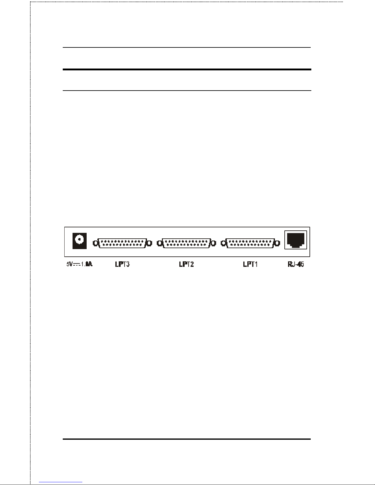
Three identical parallel ports are labeled LPT1, LPT2 and LPT3.
These printer ports are independently configurable using the PS
Admin program or the print server’s telnet interface. (See the PS
Admin User’s Guide for information about configuring the print
server’s ports.)
Rear Panel Connectors
Network Cable Connector
The Print Server’s rear panel features an RJ-45 connector for
connection to 10Base-T Ethernet cabling or 100Base-TX Fast
Ethernet cabling (which should be Category 5 twisted-pair cable).
The port supports the NWay protocol, allowing the print server to
automatically detect or negotiate the transmission speed of the
network.
Page 12
4 Introduction
DC Power Connector
The DC power input connector is located on the Print Server’s rear
panel and is labeled DC 5V.
LED Indicators
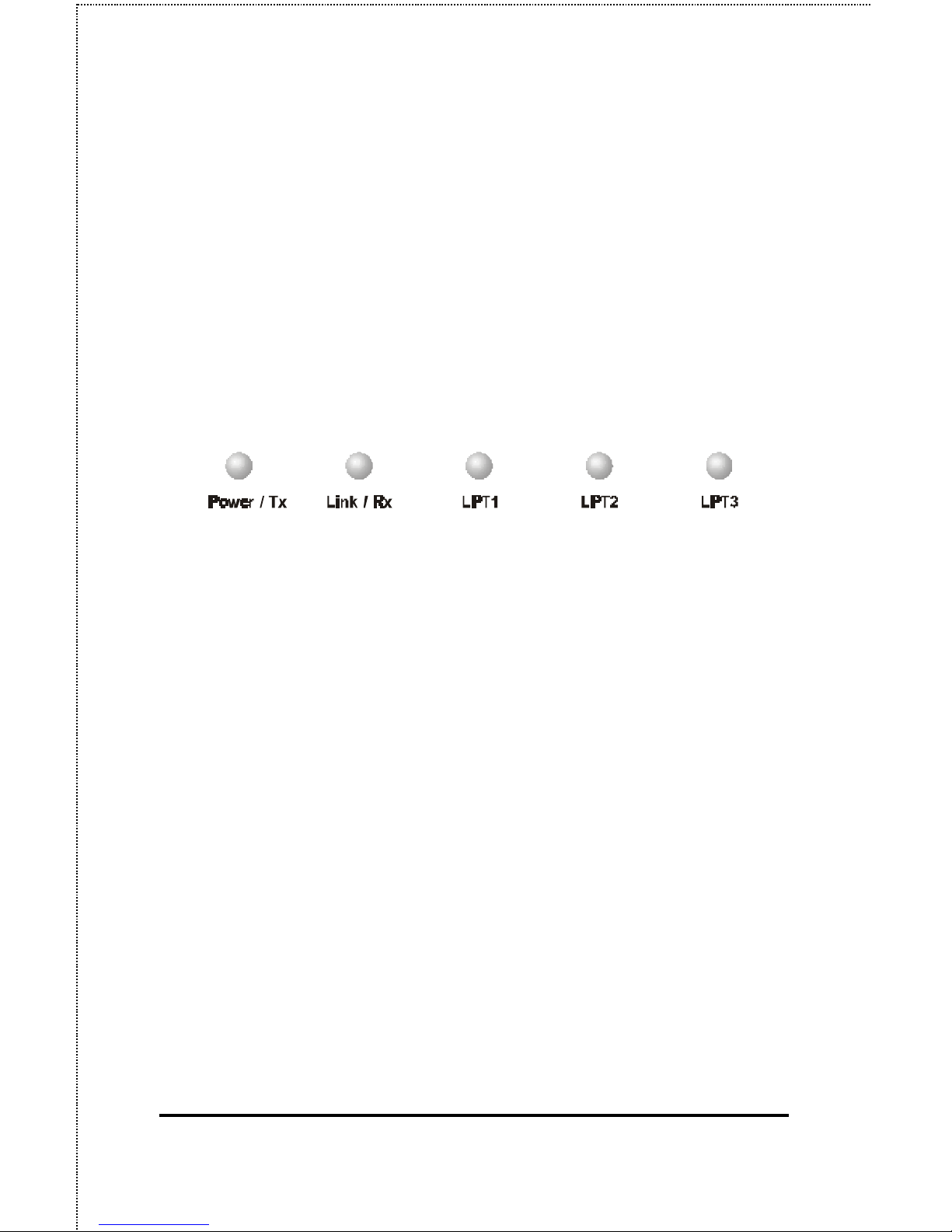
The front panel of the Print Server features five LED indicators:
Front Panel LED Indicators
♦ Power/Tx
◊ Steady or flashing green confirms that the Print Server is
powered on.
◊ The indicator blinks off briefly to indicate that the Print
Server is transmitting to the network.
♦ Link/Rx
◊ Steady or flashing green confirms that the Print Server has
a good connection to the Ethernet or Fast Ethernet network.
◊ The indicator blinks off briefly to indicate that the Print
Server is receiving from the network.
♦ LPT1, LPT2, LPT3
◊ These LED indicators light to show that the Print Server is
transferring print data through the appropriate parallel
port.
Page 13

3 Parallel Port Multiprotocol Fast Ethernet Print Server User’s Guide
Introduction 5
These three indicators are also used by the print server’s
power-on self test (POST) to indicate any hardware failures.
Page 14

6 Unpacking and Installation
2
2 UNPACKING AND
INSTALLATION
This chapter explains how to install your Print Server and connect it
to the networ k. It also describes the print server self test indications.
Unpacking and Inspecting the Print
Server
Carefully remove all items from the package. In addition to this
Hardware User’s Guide, be certain that you have:
♦ One 3 Parallel Port print server
♦ One AC power adapter suitable for your country’s electric
power
♦ One Print Server Installation CD
♦ One Quick Installation Guide
If any item is missing, or if you find any damage or mismatch,
promptly contact your dealer for assistance.
Page 15

3 Parallel Port Multiprotocol Fast Ethernet Print Server User’s Guide
Unpacking and Installation 7
Installing the Print Server
WARNING: Configuration problems may result if the Print
Server is powered up without first
establishing its network connection. Follow
this procedure to avoid complications at the
configuration stage.
1. Confirm proper operation of each of the printers to be connected
to the Print Server.
2. When you have confirmed proper operation of each printer,
switch its power off.
3. Confirm that your network is operating normally.
4. Connect the Print Server to the network, using the RJ-45
(10Base-T/100Base-TX) connector on the print server’s rear
panel.
5. While each printer is powered off, install a printer cable to
connect its parallel port to the printer port of the Print Server.
6. Switch on each connected printer.
7. Plug the AC power adapter’s DC output plug into the DC 5V
power socket on the rear panel of the Print Server.
8. Plug the power adapter into an electric service outlet. This
will supply power to the Print Server, as it has no external
power switch. The Power/Tx LED on the Print Server’s front
panel should light steady green, and the Print Server’s self-test
will pr oceed.
Page 16

8 Unpacking and Installation
Power On Self-Test
When the Print Server is powered on, it automatically performs a
self-test on each of its major components. The final result of the selftest is signaled by the state of the LPT1, LPT2, and LPT3 LED
indicators following the self-test. Preliminary to the actual
component tests, the three LED indicators are tested to confirm their
steady and flashing operation.
Immediately after power -up, all five of the LED’s should show steady
green for several seconds. Then the LPT1, LPT2, and LPT3 LEDs
should flash on simultaneously three times. Irregularity of any of
the three LEDs during these LED tests may mean there is a problem
with the LEDs themselves. Contact your dealer for correction of any
LED problems before proceeding.
The actual component tests immediately follow the LED tests. A
normal (no fault) result is signaled by a series of three cycles of
sequential flashing of the three LEDs, followed by a quiescent state
with all three LEDs dark.
If the self-test routine traps any component error, then following the
LED tests the self-test will halt and the LED’s will continuously
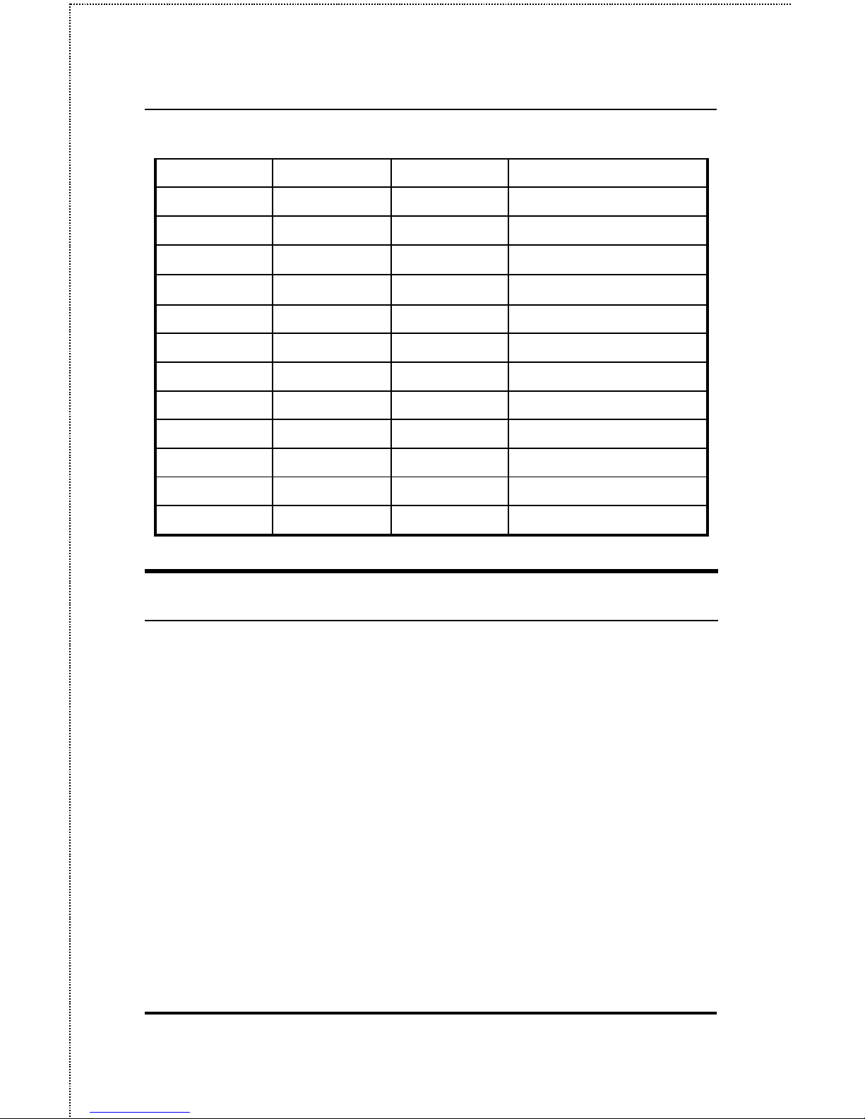
signal the error according to the following table. In the event of any
such error signal, contact your dealer for correction of the faulty unit.
LED Name
Faulty
LPT1 LPT2 LPT3
Component
off off on/steady LPT3 error
off off flashing Parallel-3 Controller error
Page 17
3 Parallel Port Multiprotocol Fast Ethernet Print Server User’s Guide
Unpacking and Installation 9
off on/steady off LPT2 error
off on/steady on/steady LAN Controller error
off on/steady flashing LAN Memory error
off flashing off
Parallel-2 Controller error
off flashing on/steady
EEPROM error
off flashing flashing Flash Protected
on/steady off off LPT1 error
on/steady off on/steady Timer INT error
on/steady off flashing LAN IO Base error
on/steady on/steady off RAM error
flashing off off Parallel-1 Controller error
flashing flashing off Flash erase/program error
flashing flashing flashing Need to reload firmware
Testing Your Print Server
The PS Admin software includes a Print Test function for
confirmation of printer cable connections and functions. That
operational test can be completed after you have installed the PS
Admin software, and have configured your Print Server and its ports.
See the Testing Your Print Server section of the PS Admin User’s
Guide.
Page 18

10 Product Specifications
A
3 P RODUCT
S PECIFICATIONS
Printer Connection
Standards: IEEE 1284 bi-directional parallel interface
Ports: Bi-directional 25-pin parallel ports × 3
Parallel Port Bi-directional Communication: Hewlett-Packard
PJL (Printer Job Language) supported
Network Connection
Network Standards : IEEE 802.3 10Base-T Ethernet, IEEE 802.3u
100BASE-TX Fast Ethernet
Network Data Transfer Rate: 10/100Mbps
Network Connector: RJ-45 connector for 10Base-T or 100BASE-
TX unshielded twisted pair connection; NWay automatic speed
negotiation supported.
Page 19

3 Parallel Port Multiprotocol Fast Ethernet Print Server User’s Guide
Product Specifications 11
Network Protocols
Ethernet Frame Types: 802.2, 802.3, Ethernet II, SNAP (autoswitching)
Transport Protocols: IPX/SPX, TCP/IP, NetBEUI,
AppleTalk/EtherTalk
TCP/IP Protocols Supported: BOOTP, SNMP, Telnet, TFTP,
FTP, lpd, RARP, DHCP
Management and Diagnostics
Standard: SNMP
MIBs: MIB-II (RFC 1213)
Diagnostic LED Indicators: Power/Tx, Link/Rx, LPT1, LPT2,
LPT3
Environmental and Physical
Power Supply: External power supply providing 5VDC input
Dimensions: 223.3mm × 131.7mm × 35mm
Weight: approx. 430g
Operating Temperature: 0 to 50°C
Storage Temperature: -25 to 55°C
Page 20

12 Product Specifications
Humidity: 5% to 95% non -condensing
Emissions: FCC Class A, CISPR 22 Class A, VCCI Class 1,
Safety: UL (UL 1950), CSA (CSA950), TUV/GS (EN 60950)
Page 21
3 Parallel Port Multiprotocol Fast Ethernet Print Server User’s Guide
Port Pinouts 13
B
4 P ORT PINOUTS
This appendix shows the pinouts of the Print Server parallel port
connector.
Parallel Ports
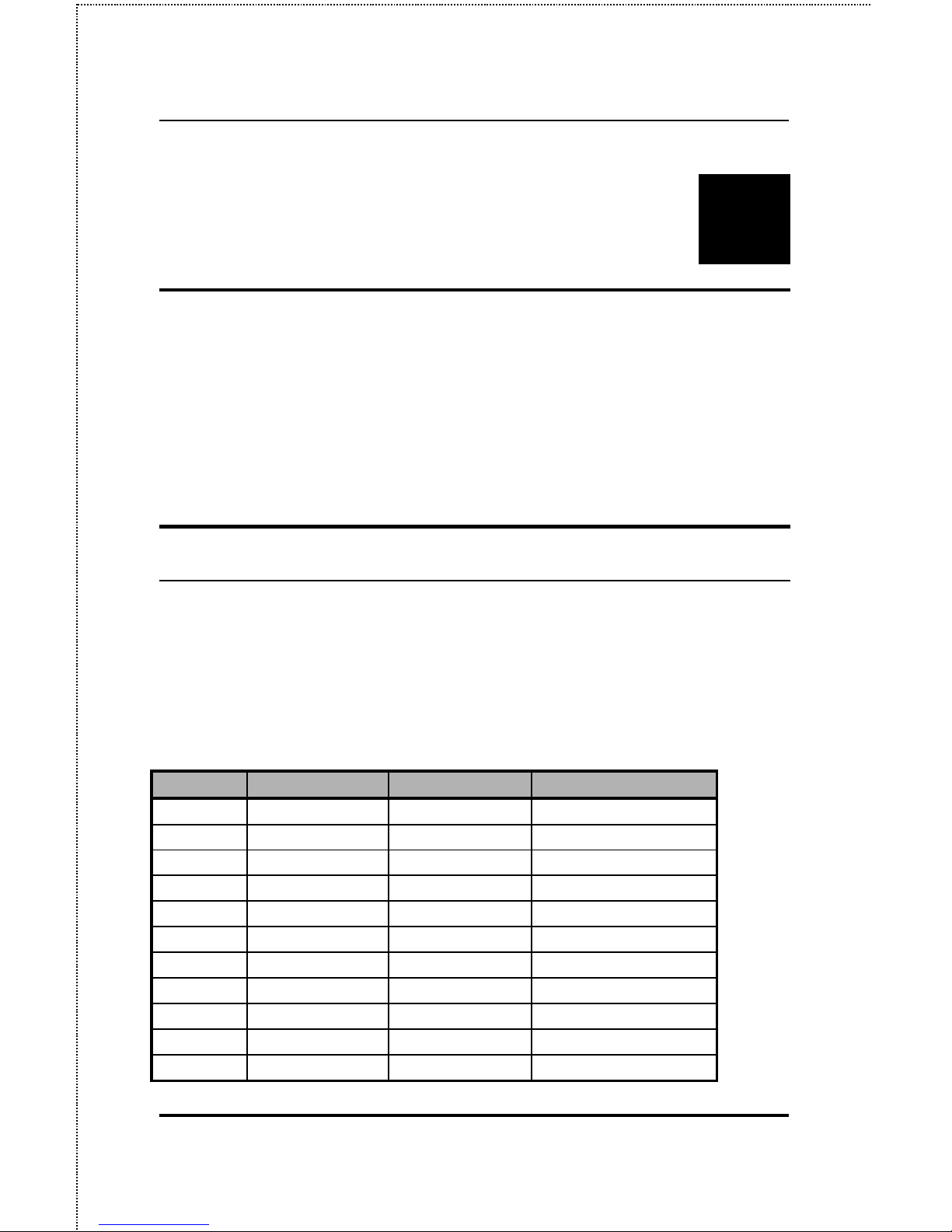
The following table lists the pinouts of the print server’s 25-pin
parallel port connector (identical to the connector used on most
personal computers), as well as the 36-pin Centronics connector used
on most printers.
Signal names beginning with n are active-low signals.
25-pin Centronics Signal Source
1 1 nStrobe Host
2 2 Data 1 Bi-directional
3 3 Data 2 Bi-directional
4 4 Data 3 Bi-directional
5 5 Data 4 Bi-directional
6 6 Data 5 Bi-directional
7 7 Data 6 Bi-directional
8 8 Data 7 Bi-directional
9 9 Data 8 Bi-directional
10 10 nAck Printer
11 11 Busy Printer
Page 22
14 Port Pinouts
25-pin Centronics Signal Source
12 12 PError Printer
13 13 Select Printer
14 14 nAutoFd Host
15 32 nFault Printer
16 31 nInit Host
17 36 nSelectIn Host
18-25 16, 17, 19-30 Ground
Page 23

 Loading...