

D-LINK DXS3424SC, DXS3424TC User guide


DXS-3400 Series Lite Layer 3 Stackable 10GbE Managed Switch Hardware Installation Guide
Information in this document is subject to change without notice. Reproduction in any manner whatsoever, without the written
permission of D-Link Corporation, is strictly forbidden.
Trademarks used in this text: D-Link and the D-LINK logo are trademarks of D-Link Corporation; Microsoft and Windows are
registered trademarks of Microsoft Corporation.
Other trademarks and trade names may be used in this document to refer to either the entities claiming the marks and names or
their products. D-Link Corporation disclaims any proprietary interest in trademarks and trade names other than its own.
© 2016 D-Link Corporation. All rights reserved.
October, 2016 P/N 651XS3400015G
FCC Warning
This equipment has been tested and found to comply with the limits for a Class A digital device, pursuant to Part 15 of the FCC
Rules. These limits are designed to provide reasonable protection against harmful interference when the equipment is operated in a
commercial environment. This equipment generates, uses, and can radiate radio frequency energy and, if not installed and used in
accordance with this manual, may cause harmful interference to radio communications. Operation of this equipment in a residential
area is likely to cause harmful interference in which case the user will be required to correct the interference at his expense.
CE Mark Warning
This equipment is compliant with Class A of CISPR 32. In a residential environment this equipment may cause radio interference.
VCCI Warning
この装置は、クラス A 情報技術装置です。この装置を家庭環境で使用すると電波妨害を引き起こすことがあります。この場合には
使用者が適切な対策を講ずるよう要求されることがあります。VCCI-A.
BSMI Notice
此為甲類資訊技術設備,於居住環境中使用時,可能會造成射頻擾動,在此種情況下,使用者會被要求採取某些適當的對策。
Safety Compliance
Warning: Class 1 Laser Product:
EN: When using a fiber optic media expansion module, never look at the transmit laser while it is powered on. Also, never
look directly at the fiber TX port and fiber cable ends when they are powered on.
FR: Ne regardez jamais le laser tant qu’il est sous tension. Ne regardez jamais directement le port TX (Tramsmission) à
fibres optiques et les embouts de câbles à fibres optiques tant qu’ils sont sous tension.
SFP (Mini-GBIC), XENPAK, and XFP Regulatory Compliance
Networks pluggable optical modules meet the following regulatory requirements:
Class 1.
IEC/EN60825-1:2007 2nd Edition or later, European Standard
FCC 21 CFR Chapter 1, Subchapter J in accordance with FDA and CDRH requirements.
Application of CE Mark in accordance with 2004/108/EEC EMC Directive and the 2006/95/EC Low Voltage Directives.
UL and/or CSA registered component for North America.
47 CFR Part 15, Class A when installed into products.
ii

DXS-3400 Series Lite Layer 3 Stackable 10GbE Managed Switch Hardware Installation Guide
Convention
Description
Boldface Font
This convention is used to place emphasis on keywords. It also indicates a
button, toolbar icon, menu, menu item, system message, or a prompt appearing
on the screen. For example, click the Apply button.
Initial capital letter
This convention is used to indicate a window name or keyboard key. For
example, press the Enter key.
Blue Courier Font
This convention is used to represent a Command Line Interface (CLI) example.
NOTE: A note indicates important information that helps you make better use of your device.
CAUTION: A caution indicates a potential for property damage, personal injury, or death.
Intended Readers
The DXS-3400 Series Lite Layer 3 Stackable 10GbE Managed Switch Hardware Installation Guide contains detailed
information about the hardware specifications of the switches in this series. It also contains brief information on how to
configure and manage a switch in this series. This manual is intended for advanced level users that are familiar with
network management concepts and terminology. For all practical reasons, all the switches in this series will simply be
referred to as the Switch throughout this manual.
Typographical Conventions
Notes and Cautions
Safety Instructions
Please pay careful attention to the following safety guidelines to ensure your own personal safety and to help protect
your system from potential damage.
Safety Cautions
To greatly reduce the risk of physical injury, electrical shock, fire, and damage to equipment, observe the following
precautions.
Observe and follow service markings.
Do not attempt to service any product, except when it is explained in the system’s documentation.
Opening or removing covers, marked with a high voltage sign, may expose the user to electrical shock.
Only a trained service technician should service components inside these compartments.
If any of the following conditions occur, unplug the product from the electrical outlet and replace the part or contact
your trained service provider:
Damage to the power cable, extension cable, or plug.
An object has fallen into the product.
The product has been exposed to water.
iii

DXS-3400 Series Lite Layer 3 Stackable 10GbE Managed Switch Hardware Installation Guide
CAUTION: Installing systems in a rack without the front and side stabilizers installed could cause the
rack to tip over, potentially resulting in bodily injury under certain circumstances. Therefore, always
install the stabilizers before installing components in the rack. After installing system/components in a
rack, never pull more than one component out of the rack on its slide assemblies at one time. The
weight of more than one extended component could cause the rack to tip over and may result in
The product has been dropped or damaged.
The product does not operate correctly when the operating instructions are correctly followed.
General safety cautions:
Keep the system away from radiators and heat sources. Also, do not block cooling vents.
Do not spill food or liquids on system components, and never operate the product in a wet environment. If the
system gets wet contact your trained service provider.
Do not push any objects into the openings of the system. Doing so can cause fire or electric shock by shorting
out interior components.
Only use this product with approved equipment.
Allow the product to cool before removing the cover or touching internal components.
Operate the product only from the type of external power source indicated on the electrical ratings label. If
unsure of the type of power source required, consult your service provider or local power company.
Be sure that attached devices are electrically rated to operate with the power available in your location.
Use only approved power cable(s). If you have not been provided with a power cable for your system or for
any AC-powered option intended for your system, purchase a power cable that is approved for use in your
country. The power cable must be rated for the product and for the voltage and current marked on the
product's electrical ratings label. The voltage and current rating of the cable should be greater than the ratings
marked on the product.
To help prevent electric shock, plug the system and peripheral power cables into properly grounded electrical
outlets. These cables are equipped with three-prong plugs to help ensure proper grounding. Do not use
adapter plugs or remove the grounding prong from a cable. If using an extension cable is necessary, use a 3wire cable with properly grounded plugs.
Observe the extension cable and power strip ratings. Make sure that the total ampere rating of all products
plugged into the extension cable or power strip does not exceed 80 percent of the ampere ratings limit for the
extension cable or power strip.
To help protect the system from sudden, transient increases and decreases in electrical power, use a surge
suppressor, line conditioner, or uninterruptible power supply (UPS).
Position system cables and power cables carefully. Route cables so that they cannot be stepped on or tripped
over. Be sure that nothing rests on any cables.
Do not modify power cables or plugs. Consult a licensed electrician or your power company for site
modifications. Always follow your local or national wiring rules.
When connecting or disconnecting power to and from hot-pluggable power supplies, observe the following guidelines:
Install the power supply before connecting the power cable to the power supply.
Unplug the power cable before removing the power supply.
If the system has multiple sources of power, disconnect power from the system by unplugging all power
cables from the power supplies.
Move products with care and ensure that all casters and stabilizers are firmly connected to the system. Avoid
sudden stops and uneven surfaces.
To help avoid damage to the system, be sure that the voltage selection switch, on the power supply, is set to match
the power available at the Switch’s location:
115V/60Hz is used mostly in North and South America as well as Far Eastern countries like as South Korea
and Taiwan
100V/50Hz is used mostly in Eastern Japan and 100V/60Hz in Western Japan
230V/50Hz is used mostly in Europe, the Middle East, Africa and the Far East
General Precautions for Rack-Mountable Products
Please pay careful attention to the following precautions concerning rack stability and safety. Systems are considered
to be components in a rack. Thus, a component refers to any system, as well as to various peripherals or supporting
hardware:
iv

DXS-3400 Series Lite Layer 3 Stackable 10GbE Managed Switch Hardware Installation Guide
serious injury.
CAUTION: Never defeat the ground conductor or operate the equipment in the absence of a suitably
installed ground conductor. Contact the appropriate electrical inspection authority or an electrician if
uncertain that suitable grounding is available.
CAUTION: The system chassis must be positively grounded to the rack cabinet frame. Do not attempt
to connect power to the system until grounding cables are connected. Completed power and safety
ground wiring must be inspected by a qualified electrical inspector. An energy hazard will exist if the
safety ground cable is omitted or disconnected.
Before working on the rack, make sure that the stabilizers are secured to the rack, extended to the floor, and
that the full weight of the rack rests on the floor. Install front and side stabilizers on a single rack or front
stabilizers for joined multiple racks before working on the rack.
Always load the rack from the bottom up, and load the heaviest item in the rack first.
Make sure that the rack is level and stable before extending a component from the rack.
Use caution when pressing the component rail release latches and sliding a component into or out of a rack;
the slide rails can pinch your fingers.
After a component is inserted into the rack, carefully extend the rail into a locking position, and then slide the
component into the rack.
Do not overload the AC supply branch circuit that provides power to the rack. The total rack load should not
exceed 80 percent of the branch circuit rating.
Ensure that proper airflow is provided to components in the rack.
Do not step on or stand on any component when servicing other components in a rack.
Protecting Against Electrostatic Discharge
Static electricity can harm delicate components inside the system. To prevent static damage, discharge static
electricity from your body before touching any of the electronic components, such as the microprocessor. This can be
done by periodically touching an unpainted metal surface on the chassis.
The following steps can also be taken prevent damage from electrostatic discharge (ESD):
When unpacking a static-sensitive component from its shipping carton, do not remove the component from
the antistatic packing material until ready to install the component in the system. Just before unwrapping the
antistatic packaging, be sure to discharge static electricity from your body.
When transporting a sensitive component, first place it in an antistatic container or packaging.
Handle all sensitive components in a static-safe area. If possible, use antistatic floor pads, workbench pads
and an antistatic grounding strap.
v

DXS-3400 Series Lite Layer 3 Stackable 10GbE Managed Switch Hardware Installation Guide
Table of Contents
Intended Readers ........................................................................................................................................................ 3
Typographical Conventions ......................................................................................................................................... 3
Notes and Cautions ..................................................................................................................................................... 3
Safety Instructions ....................................................................................................................................................... 3
Safety Cautions ...................................................................................................................................................... 3
General Precautions for Rack-Mountable Products .................................................................................................... 4
Protecting Against Electrostatic Discharge .................................................................................................................. 5
1. Introduction ............................................................................................................................................................... 8
Switch Description ....................................................................................................................................................... 8
Package Contents ........................................................................................................................................................ 8
Features ....................................................................................................................................................................... 8
Front Panel Components ........................................................................................................................................... 11
LED Indicators ...................................................................................................................................................... 12
Rear Panel Components ............................................................................................................................................ 13
Power Supply Module ........................................................................................................................................... 14
Fan Module ........................................................................................................................................................... 14
Side Panel Components ............................................................................................................................................ 15
2. Installation ............................................................................................................................................................... 16
Installation Guidelines ................................................................................................................................................ 16
Installing the Switch without a Rack .......................................................................................................................... 16
Installing the Switch into a Rack ................................................................................................................................ 17
Installing Transceivers into the Transceiver Ports ..................................................................................................... 17
Installing Power Modules into the Power Module Slots ............................................................................................. 18
Installing an AC Power Module ............................................................................................................................ 18
Installing a DC Power Module .............................................................................................................................. 19
Installing Fan Modules into the Fan Module Slots ..................................................................................................... 21
3. Switch Connections ............................................................................................................................................... 22
Switch to an End Node .............................................................................................................................................. 22
Switch to Another Switch ........................................................................................................................................... 22
Switch Stacking .......................................................................................................................................................... 23
Switch to a Server ...................................................................................................................................................... 25
4. Switch Management ............................................................................................................................................... 26
Management Options ................................................................................................................................................. 26
Connecting to the Console Port ................................................................................................................................. 26
Connecting to the RJ45 Console Port .................................................................................................................. 26
Connecting to the Mini-USB Console Port ........................................................................................................... 28
Connecting to the Switch for the First Time .......................................................................................................... 30
Creating a User Account ....................................................................................................................................... 30
Configuring the IP Address ................................................................................................................................... 31
Connecting to the MGMT Port ................................................................................................................................... 31
Connecting using SNMP ............................................................................................................................................ 32
Traps ..................................................................................................................................................................... 32
Management Information Base (MIB) ................................................................................................................... 32
5. Web-based Switch Configuration ......................................................................................................................... 33
Introduction ................................................................................................................................................................ 33
Logging into the Web UI ............................................................................................................................................ 33
Web User Interface (Web UI) ..................................................................................................................................... 34
Areas of the Web UI ............................................................................................................................................. 34
Web Pages ........................................................................................................................................................... 35
Appendix A - Technical Specifications ....................................................................................................................... 36
vi

DXS-3400 Series Lite Layer 3 Stackable 10GbE Managed Switch Hardware Installation Guide
General ...................................................................................................................................................................... 36
Physical and Environmental ....................................................................................................................................... 36
Performance............................................................................................................................................................... 37
LED Indicators ........................................................................................................................................................... 38
Port Functions ............................................................................................................................................................ 39
Appendix B - Cables and Connectors ......................................................................................................................... 41
Ethernet Cable ........................................................................................................................................................... 41
Console Cable (RJ45 to RS-232) .............................................................................................................................. 42
Console Cable (USB to Mini-USB) ............................................................................................................................ 43
Alarm Connector (RJ45) ............................................................................................................................................ 44
Warranty & Technical Support..................................................................................................................................... 45
vii

DXS-3400 Series Lite Layer 3 Stackable 10GbE Managed Switch Hardware Installation Guide
1. Introduction
Switch Description
Package Contents
Features
Front Panel Components
Rear Panel Components
Side Panel
Switch Description
DXS-3400 Series is D-Link’s latest 10G, Light Layer 3, managed switch, containing 20 10GBASE-T ports with 4
10GBASE-T/SFP+ combo ports, or 20 SFP+ ports with 4 10GBASE-T/SFP+ combo ports. The major target
application for the DXS-3400 Series is the aggregation of switches in the network, or integration of the DXS-3400
Series as the Top-of-Rack (ToR) switch in a corporation’s Data Center or server farm.
DXS-3400 Series supports a High Availability (HA) design by utilizing virtual and physical stacking, a redundant power
supply, and multiple removable fans. With stacking architecture, only a single IP address is needed to manage all
switches in the stack. The DXS-3400 Series also provides great flexibility to adding or removing a switch to and from
the network without interrupting normal network operation. The redundant power supply design provides a reliable HA
architecture to ensure non-stop operation.
The DXS-3400-24TC supports 20 10GBASE-T ports with 4 10GBASE-T/SFP+ combo ports.
The DXS-3400-24SC supports 20 10G SFP+ ports with 4 10GBASE-T/SFP+ combo ports.
The 10GBASE-T standard provides the requisite backwards compatibility that allows end users to transparently
upgrade from a 10/100/1000 Mbps network to a 10 Gbps network by using cost-effective unshielded or shielded,
Category 6, 6A, or 7 RJ45 cables.
10G SFP+ has advantages of lower power consumption, longer distance support, and better latency performance.
Package Contents
Open the shipping carton of the Switch and carefully unpack its contents. The carton should contain the following
items:
One DXS-3400 Series switch
One Quick Installation Guide
One AC power cord
One AC power supply module
Three Fan modules
One console cable (RJ45 to RS-232)
One console cable (USB to mini-USB)
One rack mounting kit (two brackets and screws)
Four rubber feet with adhesive backing
One CD containing the Web UI Reference Guide, CLI Reference Guide, D-View module, and additional
software
If any item is missing or damaged, please contact your local D-Link reseller for replacement.
Features
This switch is packed with an abundance of networking features that span inside and outside of the traditional Layer 3
framework. The list below highlights the significant protocols and features supported by this switch.
8

DXS-3400 Series Lite Layer 3 Stackable 10GbE Managed Switch Hardware Installation Guide
Features that can be found on this switch are:
Virtual Stacking. D-Link Single IP Management
(SIM)
Physical Stacking, using the SFP+ ports with
80G (full-duplex) in Linear and Ring topologies
Jumbo Frames (12 KBytes)
Spanning Tree Protocol (STP, RSTP, and
MSTP)
Ethernet Ring Protection Switching (ERPS)
Link Aggregation
Mirroring (Port Mirroring, VLAN Mirroring,
Flow-based (ACL) Mirroring, and RSPAN)
Loopback Detection (LBD)
L2 Protocol Tunneling
IGMP Snooping (Version 1, 2, and 3)
MLD Snooping (Version 1 and 2)
PIM Snooping
Priority-based Flow Control (PFC) on 10G
ports
802.1Q VLAN, Port-based VLAN, 802.1v
Protocol-based VLAN , MAC-based VLAN,
Subnet-based VLAN, Voice VLAN,
Surveillance VLAN, Private VLAN, Asymmetric
VLAN, and VLAN Trunking
Double VLAN (Q-in-Q) and VLAN Translation
ISM VLAN (Multicast VLAN)
Gratuitous ARP
ARP Proxy
IPv6 Neighbor Discovery (ND)
IPv6 Tunneling
Virtual Router Redundancy Protocol
(VRRPv2/VRRPv3)
Policy-based Route (PBR)
Route Preference Setting
Route Redistribution
Bidirectional Forwarding Detection (BFD)
Routing Information Protocol (RIPv1/RIPv2),
and RIPng
Class of Service (CoS)
Single-rate Three-color Marker (srTCM) and
Two-rate Three-color Marker (trTCM)
Policy Map (Remark 802.1p priority, Remark
ToS/DSCP, Rate Limiting, and Time-based
QoS)
Queue Handling: Strict Priority Queue (SPQ),
Weighted Round Robin (WRR), SPQ+WRR,
Weighted Deficit Round Robin (WDRR), and
802.1Qaz Enhanced Transmission Selection
(ETS)
Congestion Control: Weighted Random Early
Detection (WRED), 802.1Qau Congestion
Notification (QCN), Port-based Bandwidth
Control, Flow-based bandwidth Control, and
Queue-based Bandwidth Control
Access Control List (ACL): IP Access List,
IPv6 Access List, Time-based ACL, and CPU
Interface Filtering
iSCSI Awareness
Secure Shell (SSHv2) IPv4/IPv6
Secure Sockets Layer (SSLv1/SSLv2/SSLv3)
IPv4/IPv6
Port Security
Broadcast, Multicast, and Unicast Storm
Control
Traffic Segmentation
IP-MAC-Port Binding (IMPB)
IP Source Guard (IPv4/IPv6)
DHCP Snooping
IPv6 Snooping
Dynamic ARP Inspection (DAI)
DHCPv6 Guard
IPv6 Route Advertisement (RA) Guard
IPv6 ND Inspection
Duplicate Address Detection (DAD)
D-Link Safeguard Engine
Layer 3 Control Packet Filtering
NetBIOS/NetBEUI Filtering
DHCP Server Screening (IPv4/IPv6)
DHCP Client Filtering
ARP Spoofing Prevention
BPDU Attack Protection
DoS Attack Prevention
Authentication, Authorization, and Accounting
(AAA)
RADIUS/TACACS+ Accounting (IPv4/IPv6)
802.1X Network Access Control
Web-based Access Control (WAC)
MAC-based Access Control (MAC)
Compound Authentication
Guest VLAN
Microsoft® NAP Support (IPv4/IPv6)
9

DXS-3400 Series Lite Layer 3 Stackable 10GbE Managed Switch Hardware Installation Guide
Trusted Host
Cable Diagnostics
802.3ah Ethernet Link OAM (Dying Gasp)
802.1ag Connectivity Fault Management (CFM)
Y.1731 OAM
Optical Transceiver Digital Diagnostic
Monitoring (DDM)
D-Link Unidirectional Link Detection (DULD)
Network Time Protocol (NTP) IPv4/IPv6
Simple Network Time Protocol (SNTP)
IPv4/IPv6
Precision Time Protocol (PTP)
Link Layer Discovery Protocol (LLDP), and
LLDP-MED
User Account Privilege for Management
Access
Command Line Interface (CLI)
Simple Network Management Protocol
(SNMPv1/SNMPv2c/SNMPv3) IPv4/IPv6
Remote Network MONitoring
(RMONv1/RMONv2)
SNMP Trap
Web User Interface (Web UI)
D-Link Discover Protocol (DDP), and D-Link
Network Assistant (DNA)
DHCP Server and Client, and DHCP Auto-
configuration (IPv4/IPv6)
DHCP Relay (IPv4/IPv6)
Telnet Server and Client
TFTP Client (IPv4/IPv6)
FTP Client (IPv4/IPv6)
Secured FTP (SFTP) Server (IPv4/IPv6)
Remote Copy Protocol (RCP) IPv4/IPv6
System Log and Command Logging
SMTP (IPv4/IPv6)
DNS Resolver and Relay (IPv4/IPv6)
Multiple Image and Configuration, and Flash
File System (FFS)
Password Recovery and Encryption
Debug Command
CPU and Port Utilization Monitoring, and
Packets Counter
Trap and Log Severity Control
Traceroute and Ping (IPv4/IPv6)
Microsoft® Network Load Balancing (NLB)
sFlow (IPv4/IPv6)
Management Information Base (MIBs) for
MIBII, Bridge MIB, SNMPv2 MIB, RMON MIB,
RMONv2 MIB, Ether-like MIB, 802.3 MAU MIB,
802.1p MIB, IF MIB, RADIUS Authentication
Client MIB, RADIUS Accounting Client MIB,
Ping & TRACEROUTE MIB, IPv6 MIB,
ICMPv6 MIB, Entity MIB, VRRP MIB, RIPv2
MIB, OSPF MIB, IPv4 Multicast Routing MIB,
PIM MIB for IPv4, IP Forwarding Table MIB,
IPv6 SNMP MGMT Interface MIB, DDM MIB,
Private MIB, and D-Link Zone Defense MIB
10
DXS-3400 Series Lite Layer 3 Stackable 10GbE Managed Switch Hardware Installation Guide
Port
Description
Alarm
The RJ45 (8 pins) Alarm port provides an external alarm detection. The Switch
will send out the traps and logs when two of the pins are shorted among the pair.
USB
Inserting a flash drive into the USB 2.0 Type-A port provides an additional
storage space for portable firmware images and configuration files that can be
copied to and from the NVRAM of the Switch.
MGMT
The RJ45 MGMT port is an out-of-band management port that operates at
10/100/1000 Mbps wire-speed. This port can be used to configure the Switch
without being connected to the network.
Console (RJ45)
The RJ45 console port can be used to connect to the Command Line Interface
(CLI) of the Switch for configuration, management, and monitoring. This port
uses a special console cable (included in this package) with a DB9 interface to
connect the Switch to the serial port (COM) of the PC.
Console (Mini-USB)
The Mini-USB console port can be used to connect to the Command Line
Interface (CLI) of the Switch for configuration, management, and monitoring.
10 Gigabit RJ45 Ports
The DXS-3400-24TC is equipped with 20 RJ45 Ethernet ports. These ports can
operate at 100/1000/10000 Mbps wire-speeds.
10 Gigabit SFP+ Ports
The DXS-34000-24SC is equipped with 20 SFP/SFP+ por ts. These ports can
operate at 1/10 Gbps wire-speeds and support a wide collection of SFP/SFP+
transceivers.
10 Gigabit Combo RJ45/SFP+
Ports
The Switch is equipped with 4 combo ports that can either operate as RJ45
Ethernet ports or SFP/SFP+ ports. The RJ45 ports can operate at
100/1000/10000 Mbps wire-speeds. The SFP/SFP+ ports can operate at 1/10
Gbps wire-speeds and support a wide collection of SFP/SFP+ transceivers.
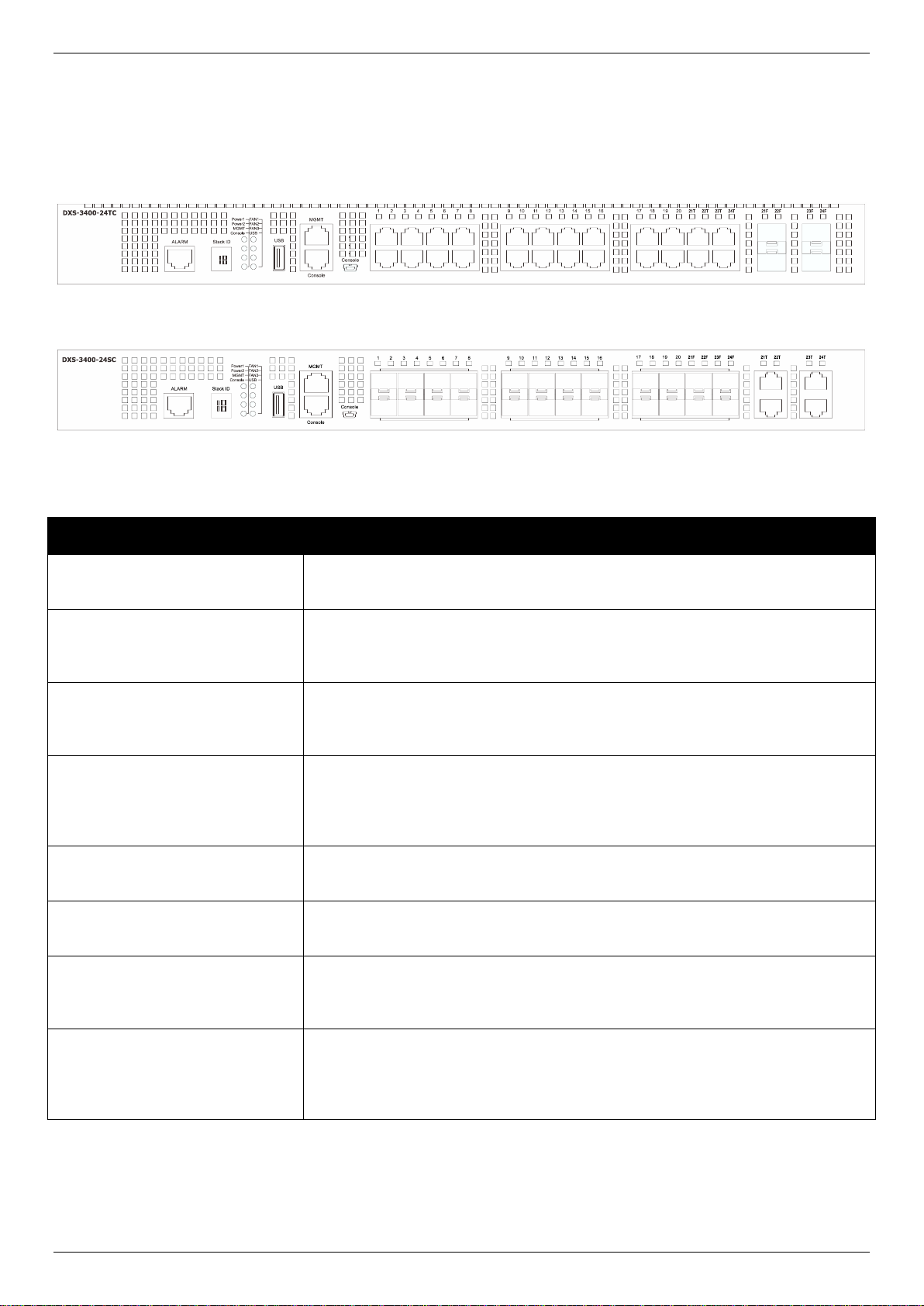
Front Panel Components
The front panel of the Switches in this series features a variety of LED indicators and ports.
Figure 1-1 Front panel view of the DXS-3400-24TC
Figure 1-2 Front panel view of the DXS-3400-24SC
Ports that can be found on the front panel of this switch are listed in the table below.
For a complete list of SFP/SFP+ transceivers that are compatible with this switch, refer to the SFP+ Ports section in
Appendix A - Technical Specifications.
11
DXS-3400 Series Lite Layer 3 Stackable 10GbE Managed Switch Hardware Installation Guide
LED
Description
Stack ID
This 7-segment LED can display numbers from 1 to 4 and the following letters H,
h, E, and G. The stacking ID (1 to 4) can be assigned manually by the user or
automatically by the system.
The letter ‘H’ will be displayed if this switch is the master switch in the stack.
The letter ‘h’ will be displayed if this switch is the backup master switch in the
stack.
The letter ‘E’ will be displayed if there was an error in the system’s self-test.
The letter ‘G’ will be displayed when the Safeguard engine entered the
exhausted mode.
Power 1, Power 2
This LED will light solid green after the Switch has been powered on
successfully.
This LED will light solid amber if the Switch’s power supply fails.
This LED will be off when the Switch is no longer receiving power (i.e. powered
off).
Management (MGMT)
This LED will light solid green after a link to the management port was
successfully established.
This LED will blink when activity on this port is taking place.
This LED will be off when there is no link present or when this interface was shut
down from within the Switch’s configuration.
Console
This LED will light solid green when the RJ45 console port is active.
The LED will light solid amber when the mini-USB console port is active.
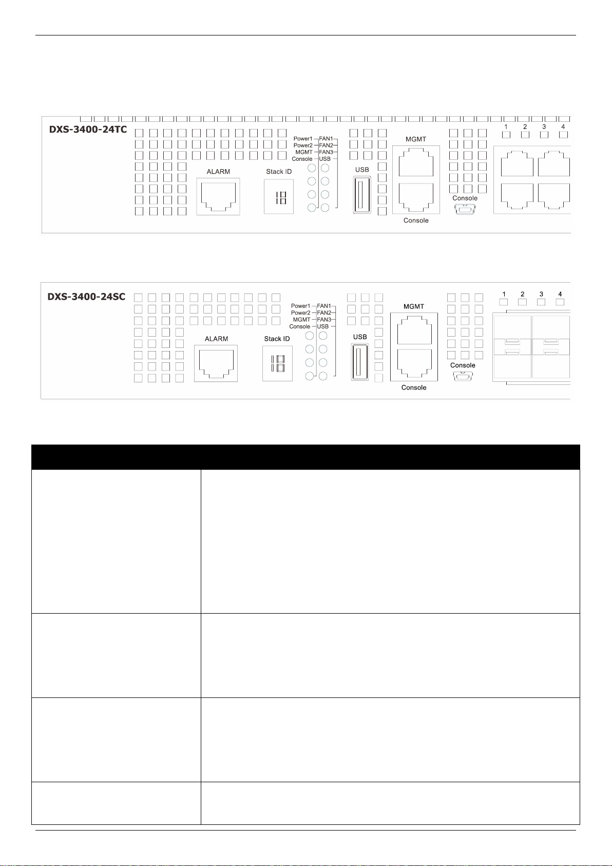
LED Indicators
Located on the front panel of the Switch are LED indicators: Stack ID, Power1, Power2, MGMT, Console, Fan1, Fan2,
Fan3, and USB. For each port there is a light representing the port speed and activity.
Figure 1-3 LED indicators for the DXS-3400-24TC
Figure 1-4 LED indicators for the DXS-3400-24SC
12
DXS-3400 Series Lite Layer 3 Stackable 10GbE Managed Switch Hardware Installation Guide
LED
Description
This LED will be off when both console ports are not active.
Fan1, Fan2, Fan3
This LED will light solid green when the fan is operating normally.
This LED will light solid amber when the Switch is booting up or when a
diagnostics test is taking place.
This LED will blink amber when a fan fails.
This LED will be off when the fan is not receiving power.
USB
This LED will light solid green if a USB flash drive is plugged in.
This LED will blink green when the Switch is reading or writing data to and from
the USB drive.
This LED will be off when no USB drive is plugged into the USB port.
This LED will light solid red when a USB drive failure has been detected.
Port LEDs
This LED will light solid green when there is a connection to a 10 Gbps Ethernet
device on any of the ports.
This LED will light solid amber when there is a connection to a 100/1000 Mbps
Ethernet device on any of the RJ45 ports.
This LED will light solid amber when there is a connection to a 1 Gbps Ethernet
device on any of the SFP+ fiber ports.
This LED will blink when a port is active.
This LED will be off when there is no link or activity.
Refer to the LED Indicators section in the Appendix A - Technical Specifications for more LED information.
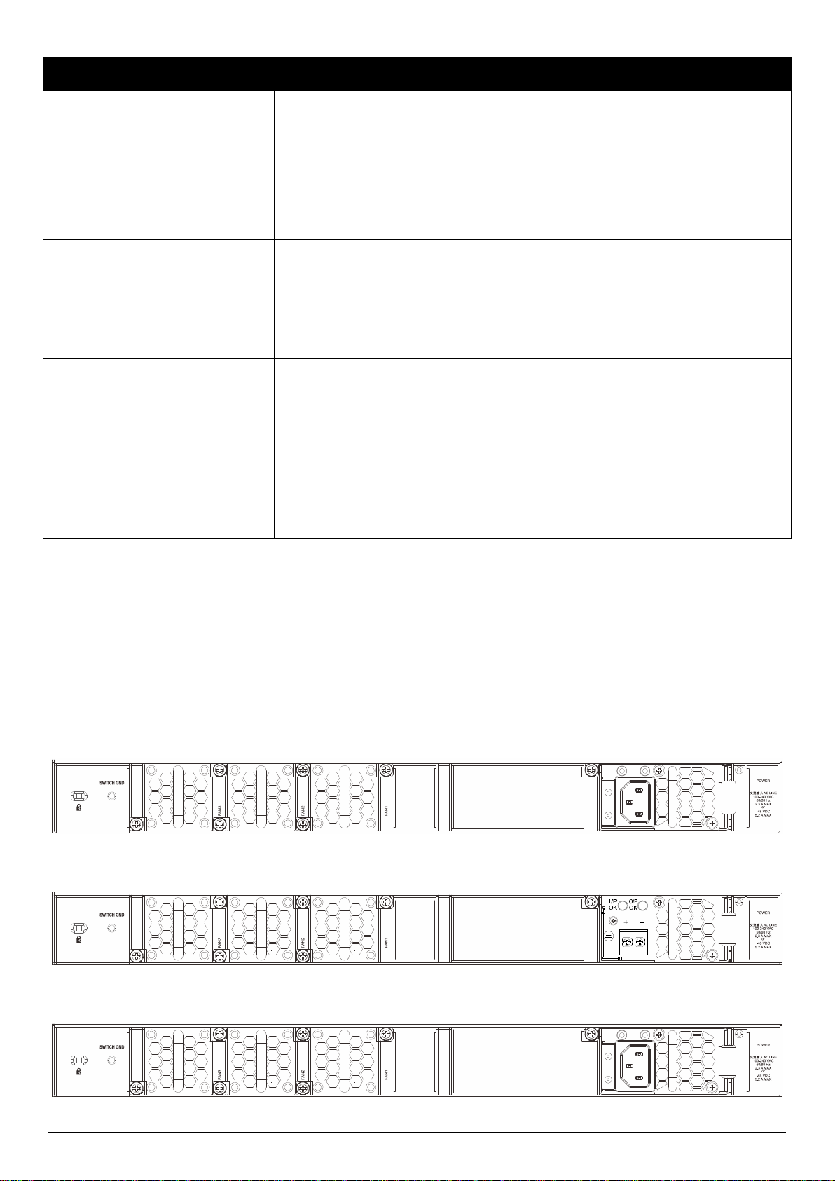
Rear Panel Components
The rear panel of the Switches in this series features a security lock, a GND, power supply module slots, and fan
module slots. One AC power supply module and three fan modules are included in the package for the Switch.
Any additional power supply module needs to be bought separately. This switch also supports the use of a DC power
supply module.
Figure 1-5 Rear panel view of the DXS-3400-24TC with an AC Power Supply
Figure 1-6 Rear Panel view of the DXS-3400-24TC with a DC Power Supply
Figure 1-7 Rear panel view of the DXS-3400-24SC with a AC Power Supply
13
DXS-3400 Series Lite Layer 3 Stackable 10GbE Managed Switch Hardware Installation Guide
Component
Description
Security Lock
Provide a Kensington-compatible security lock to be able to connect to a secure
immovable device. Insert the lock into the notch and turn the key to secure the
lock. The lock-and-cable apparatus should be purchased separately.
Switch GND
Use an electrical grounding wire and connect one end of the wire to the Switch
GND and the other end of the wire to an electrical grounding point most
commonly found on the Switch mounting rack itself.
Three Fan Module Slots
These slots can be equipped with the following fan module.
DXS-FAN100 (Normal fan tray with front-to-back airflow)
Two Power Supply Module
Slots
These slots can be equipped with the following additional power modules. Only
one power supply module is included. Any additional modules should be bought
separately.
DXS-PWR300AC (300 Watt AC power supply tray with front-to-back
airflow)
DXS-PWR300DC (300 Watt DC power supply tray with front-to-back
airflow)
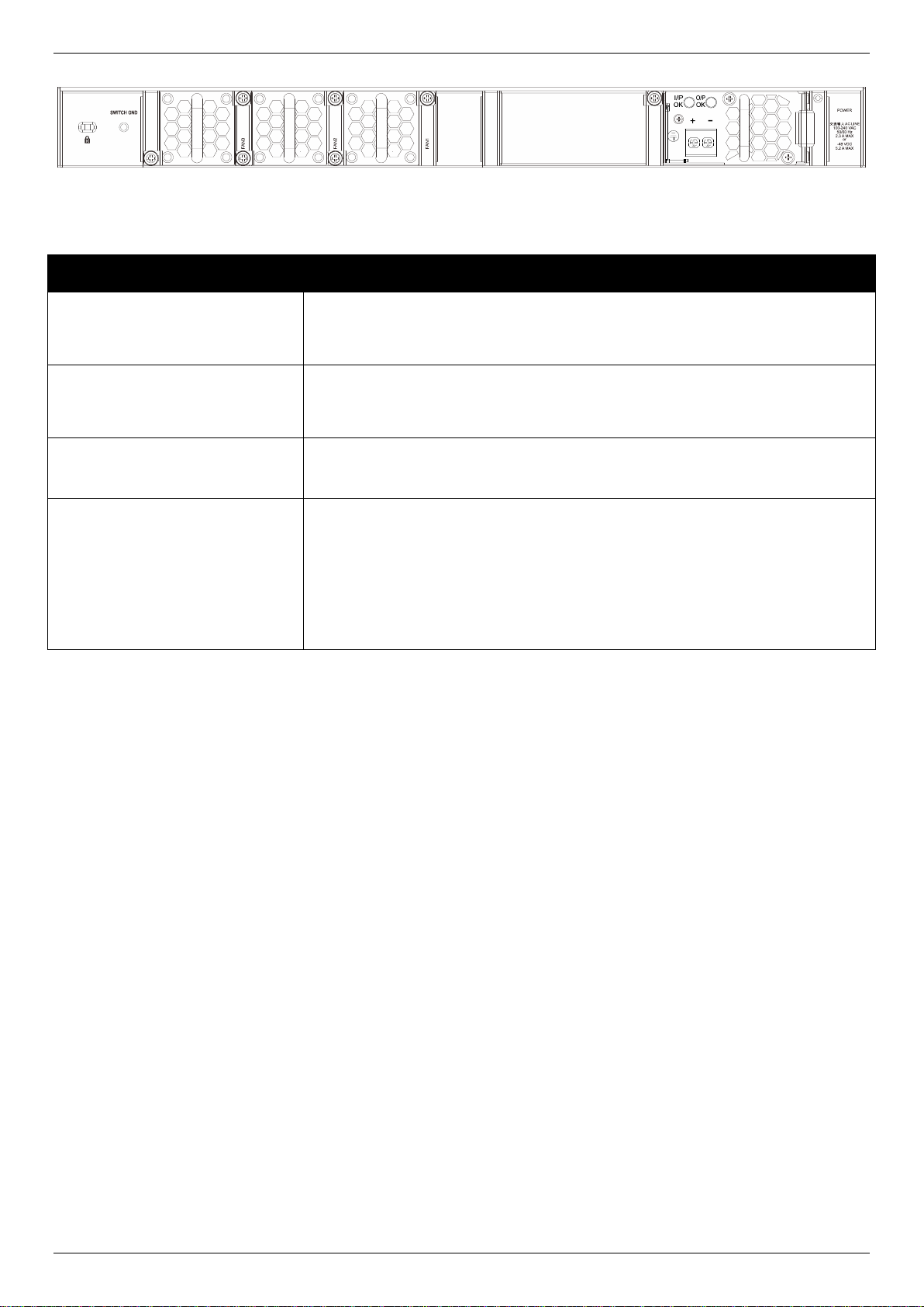
Figure 1-8 Rear Panel view of the DXS-3400-24SC with a DC Power Supply
Components that can be found on the rear panel of this switch are listed in the table below.
Power Supply Module
Connect the one end of the AC power cord supplied to the AC power connector and the other end into a properly
grounded electrical outlet. The Switch will automatically adjust the power setting to adapt to any voltage supply in the
range from 100~240 VAC at 50~60 Hz. In addition, an optional second power supply module can be plugged into the
second power supply connector slot. The primary and secondary power supply can be either AC supplied or DC
supplied, depending on the power supply module inserted. This makes it dual redundant.
Fan Module
The fan modules on the Switch provide front-to-back airflow and are hot-swappable. The Switch also includes smart
fans that will automatically change their speed depending on the internal temperature detected by the sensors built-in
the hardware. These smart fans support two states. They can either running at a low speed, or running at a high
speed.
The following will explain when these fans will toggle between low and high speeds:
DXS-3400-24TC: When the internal temperature, detected by the sensor, rises above 37 °C, the fan will
automatically change to the high speed. When the internal temperature, detected by the sensor, falls below 33
°C, the fan will automatically change to the low speed.
DXS-3400-24SC: When the internal temperature, detected by the sensor, rises above 39 °C, the fan will
automatically change to the high speed. When the internal temperature, detected by the sensor, falls below 36
°C, the fan will automatically change to the low speed.
14
DXS-3400 Series Lite Layer 3 Stackable 10GbE Managed Switch Hardware Installation Guide
Side Panel Components
The side panels of the Switches in this series feature rack-mounting bracket screw holes that can be used when the
Switch is installed into a rack-mount unit.
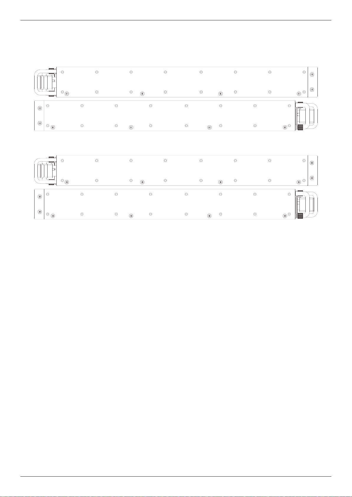
Figure 1-9 Side panels of the DXS-3400-24TC
Figure 1-10 Side panels of the DXS-3400-24SC
15

DXS-3400 Series Lite Layer 3 Stackable 10GbE Managed Switch Hardware Installation Guide
2. Installation
Installation Guidelines
Installing the Switch without a Rack
Installing the Switch into a Rack
Installing Transceivers into the Transceiver Ports
Installing Power Modules into the Power Module
Installing Fan Modules into the Fan Module
Installation Guidelines
This section will discuss the hardware installation guidelines that the user must follow in order to properly and safely
install this switch into the appropriate environment.
Visually inspect the power cord and see that it is fully secured to both the power connector, on the Switch, and
the electrical outlet that supplies power.
Install the Switch in a fairly cool and dry place within the acceptable operating temperature and humidity
ranges. For more information about the acceptable operating temperature and humidity ranges, refer to the
Physical and Environmental section.
Install the Switch in a site free from strong electromagnetic field generators such as motors, vibration, dust,
and direct exposure to sunlight.
Installing the Switch without a Rack
This section is used to guide the user through installing the Switch in an area other than a switch rack. Attach the
included rubber feet to the bottom of the Switch. Take note that there should be marked blocks on the bottom of the
Switch to indicate where to attach the rubber feet. These markings are usually found in each corner on the bottom of
the device. The rubber feet cushion the Switch, protecting the casing from scratches and preventing it from scratching
other surfaces.
Figure 2-1 Attaching rubber feet to the Switch
Install the Switch on a sturdy, level surface that can support the weight of the Switch (see the Weight section in
Appendix A - Technical Specifications.). Do not place any heavy objects on the Switch. The power outlet should be
within 1.82 meters (6 feet) of the Switch. Make sure that there is proper heat dissipation from and adequate ventilation
around the Switch. Leave at least 10 cm (4 inches) of space at the front and rear of the Switch for ventilation. Without
proper heat dissipation and air circulation, system components might overheat which could lead to system failure or
even severely damaged components.
16

DXS-3400 Series Lite Layer 3 Stackable 10GbE Managed Switch Hardware Installation Guide
Installing the Switch into a Rack
This section is used to guide the user through installing the Switch into a switch rack. The Switch can be mounted in a
standard 19" (1 U) rack using the provided mounting brackets.
1. Fasten the mounting brackets to the sides of the Switch using the screws provided.
Figure 2-2 Attaching rack-mount brackets to the Switch
2. Fasten the mounting brackets in any available open space in the rack using the screws provided.
Figure 2-3 Installing the Switch in a Rack
Make sure that there is adequate space around the Switch to allow for proper air flow, ventilation, and cooling.
Installing Transceivers into the Transceiver Ports
The Switch is equipped with Enhanced Small Form-factor Pluggable (SFP+) ports that can be used to connect various
other networking devices to this switch that do not support the standard RJ45 wiring connection. These ports are
17

DXS-3400 Series Lite Layer 3 Stackable 10GbE Managed Switch Hardware Installation Guide
generally used to connect this switch to optical fiber connections and can be used to connect devices to the Switch
over great distances. The maximum distance that the RJ45 wiring connection can reach is 100 meters. Fiber optic
connections can span several kilometers.
The figure below illustrates how to properly insert SFP+ transceivers into the Switch’s SFP+ ports.
Figure 2-4 Inserting transceivers into the transceiver ports
The SFP+ ports also support other transceiver form factors like SFP and SFP+ transceivers. A complete list of
SFP/SFP+ transceivers, compatible with this switch, can be found the SFP+ Ports section in Appendix A - Technical
Specifications at the end of this document.
Installing Power Modules into the Power Module Slots
The power module slots, located on the rear panel of this switch, support two types of power supply modules.
AC Power Supply Module:
DXS-PWR300AC: A 300 Watt AC power supply tray with front-to-back airflow.
DC Power Supply Module:
DXS-PWR300DC: A 300 Watt DC power supply tray with front-to-back airflow.
Installing an AC Power Module
Insert the AC power supply module into the power module slot until the clip clicks in place. Connect the one end of the
AC power cord supplied to the AC power connector and the other end into a properly grounded electrical outlet. The
Switch will automatically adjust the AC power setting to adapt to any voltage supply in the range from 100~240 VAC at
50~60 Hz.
18

DXS-3400 Series Lite Layer 3 Stackable 10GbE Managed Switch Hardware Installation Guide
Figure 2-5 Installing an AC Power Supply Module
Figure 2-6 Installed AC Power Supply Module
In addition, an optional second AC power supply module can be plugged into the second power supply module slot, as
displayed above. When two AC Power supply modules are inserted, and both are supplying power to the Switch, the
AC power load will be shared between them. When one of the AC power supply modules fails, the other AC power
supply module will continue to supply power to the Switch automatically.
The AC power supply modules are hot-swappable, meaning, that they can be inserted and removed while the Switch
is powered on. This feature enhances the reliability of this switch.
Installing a DC Power Module
This switch supports a unique dual power input feature. Insert the DC power supply module into the power module slot
until the clip clicks in place. Connect the one end of the DC power cord supplied to a DC power source (-48 VDC, 5.2
A). Make sure that connection polarity (positive and negative) is correct before supplying DC power to the Switch to
avoid any damage to the Switch. Connect the power source to the DC plug before plugging it into the Switch. This will
protect the Switch from a possible shortage on the DC cable.
19
 Loading...