

D-Link DIS-300G Quick Installation Manual
Quick Installation Guide
1
DIS-300G Series Managed Industrial Gigabit
Ethernet Switch
Quick Installation Guide
Overview
The Managed Ethernet Switch solutions are designed for supporting standard industrial
applications. Managed switches are easier to prioritize, partition, and organize user’s
network, providing a more reliable and better quality services.
Package Checklist
Please verify the box contains the following items:
Item Quantity
Management Ethernet switch 1
Wall-mount plates 2
DIN-Rail CLIP 1
M3 Screws (for the wall mount plates & DIN CLIP) 4
DC power terminal block 1
RJ45 Ethernet port Dust Cover Some
SFP Ethernet port Dust cover Same as SFP port number
Quick Installation Guide
2
Safety Instructions
When a fiber connection is removed during installation, testing, servicing or an active fiber is
broken, ocular exposure to optical energy may be potentially hazardous, depending on the
laser output power.
The primary hazards of exposing laser radia ti on fro m an opti cal -fiber communication systems
are:
●
Damage to eyes from accidental exposure to a beam emitted by a laser source.
●
Damage to eyes from v i ewi ng the connec t or that att ac hes to a brok en fiber or an
energized fiber.
If the equipment is used in a manner not specified by the manufacturer, the protection
provided by the equipment may be impaired.
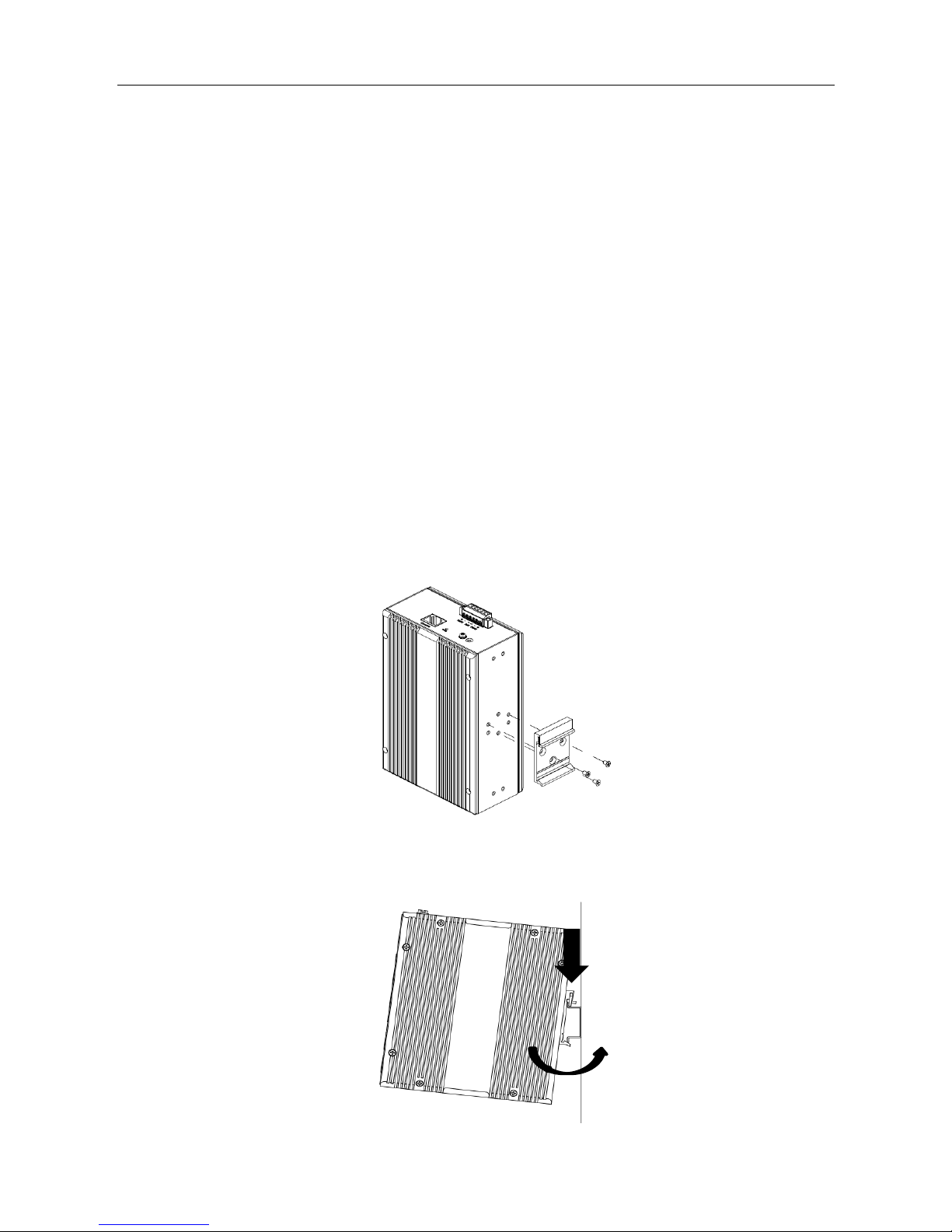
DIN-Rail Mounting
Mounting steps:
1. Screw the din-clip with screws in the accessory kit.
2. Hook the unit onto the din-rail.
3. Push the bottom of the unit towards the din-rail until it locks in place.
2
3
Quick Installation Guide
3
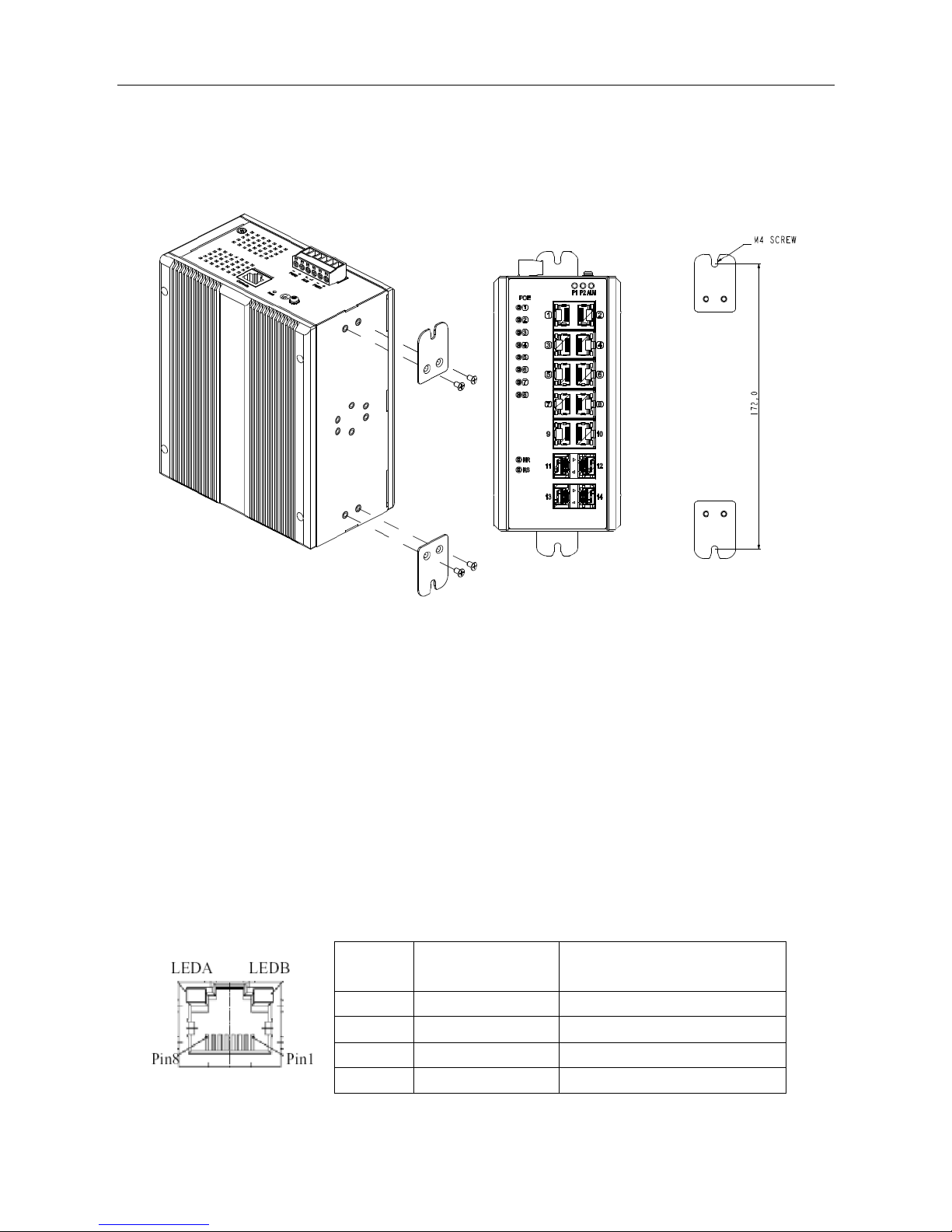
Wall Mounting
Mounting steps:
1. Screw the wall-mount brackets with screws in the accessory kit.
< This graph is for all DIS-300G series >
Ethernet Interface (RJ45 Ethernet)
The switch provides two types of Ethernet interfaces: electrical (RJ45) and optical (SFP)
interfaces.
Connecting the Ethernet interface via RJ45:
●
To connect the switch to a PC, use straight-through or cross-over Ethernet cables,
●
To connect the switch to an Ethernet device, use UTP (Unshielded Twisted Pair)
or STP (Shielded Twisted Pair) Ethernet cables.
The pin assignment of RJ-45 connector is shown in the following figure and table.
Pin Assignment
PoE Assignment
(for DIS-300G-8PSW/DIS-300G-
14PSW only)
1,2 T/Rx+,T/Rx- Positive VPort
3,6 T/Rx+,T/Rx- Negative VPort
4,5 T/Rx+,T/Rx- X
7,8 T/Rx+,T/Rx- X
 Loading...