

Page 1

Rev. 02 (August 2000)
6DI308.…02
Printed in Taiwan
DI-308
ISDN Router
User’s Guide
RECYCLABLE
Page 2

Copyright Statement
Copyright ©2000 D-Link Corporation
No part of this publication may be reproduced in any form or by any means or used
to make any derivative such as translation, transformation, or adaptation without
permission from D-Link Corporation/D-Link Systems Inc., as stipulated by the
United States Copyright Act of 1976.
Trademarks
D-Link is a registered trademark of D-Link Corporation/D-Link Systems, Inc.
All other trademarks belong to their respective owners.
FCC Warning
This equipment has been tested and found to comply with the limits for a Class B digital device, pursuant to Part
15 of the FCC Rules. These limits are d esi gned to provide reason able protection again st harmful interference in
a residential installation. This equipment generates, uses, and can radiate radio frequency energy and, if not
installed and used in accordance with the inst ructions, may cause harmful interference to radio communications.
However, there is no guarantee that interference will not occur in a particular installation. If this equipment does
cause harmful interference to radio o r t elevision reception, which can be determined by turning t he equipment
off and on, the user is en couraged to try to correct th e interference by one or more of the following measures:
• Reorient or relocate the receiving antenna.
• Increase the separation between the equipmen t and receiver.
• Connect the equipment into an outlet on a circu it different from that to which the receiver is connected.
• Consult the dealer or an experienced radio/TV technician for help.
Shielded interface cables must b e used in order to comply with emission l i mits.
You are cautioned that changes or modifications not expressly approved by the party responsible for compliance
could void your authority to operate the equipment.
This device complies with part 15 of the FCC Rules. Operation is subject to the following two conditions: (1)
This device may not cause harmful interference, and (2 ) this device must accept any interference received,
including interference that may cause undesired operation.
CE Mark Warning
This is a Class B product. In a domestic environment, this product may cause radio interference in which case
the user may be required to take adequate measures.
Page 3

Limited Warranty
Hardware:
D-Link warrants each of its hardware products to be free from defects in workmanship and materials under normal use and
service for a period commencing on the date of purchase from D-Link or its Authorized Reseller and extending for the length of
time stipulated by the Authorized Reseller or D-Link Branch Office nearest to the place of purchase.
This Warranty applies on the condition that the product Registration Card is filled out and returned to a D-Link office within
ninety (90) days of purchase. A list of D-Link offices is provided at the back of this manual, together with a copy of the
Registration Card.
If the product proves defective within the applicable warranty period, D-Link will provide repair or replacement of the product.
D-Link shall have the sole discretion whether to repair or replace, and replacement product may be new or reconditioned.
Replacement product shall be of equivalent or better specifications, relative to the defective product, but need not be identical.
Any product or part repaired by D-Link pursuant to this warranty shall have a warranty period of not less than 90 days, from
date of such repair, irrespective of any earlier expiration of original warranty period. When D-Link provides replacement, then
the defective product becomes the property of D-Link.
Warranty service may be obtained by contacting a D-Link office within the applicable warranty period, and requesting a
Return Material Authoriza tion (RMA) number. If a Reg istration Card for the product in question has not been returned to
D-Link, then a proof of purchase (such as a copy of the dated purchase invoice) must be provided. If Purchaser's circumstances
require special handling of warranty correction, then at the time of requesting RMA number, Purchaser may also propose
special procedure as may be suitable to the case.
After an RMA number is issued, the defective product must be packaged securely in the original or other suitable shipping
package to ensure that it will not be damaged in transit, and the RMA number must be prominently marked on the outside of
the package. The package must be mailed or otherwise shipped to D-Link with all costs of mailing/shipping/insurance prepaid.
D-Link shall never be responsible for any sof tw are, firmware, information, or memory data of Purchaser contained in, stored
on, or integrated with any product returned to D-Link pursuant to this warranty.
Any package returned to D-Link without an RMA number will be rejected and shipped back to Purchaser at Purchaser's
expense, and D-Link reserves the right in such a case to levy a reasonable handling charge in addition mailing or shipping
costs.
Software:
Warranty service for software products may be obtained by contacting a D-Link office within the applicable warranty period.
A list of D-Link offices is provided at the back of this manual, together with a copy of the Registration Card. If a Registration
Card for the product in question has not been returned to a D-Link office, then a proof of p urchase (such as a copy of the dated
purchase invoice) must be provided when requesti ng warranty service. The term "purchase" in this software warranty refers
to the purchase transaction and resulting license to use such software.
D-Link warrants that its software products will perform in substantial conformance with the applicable product
documentation provided by D-Link with such software product, for a period of ninety (90) days from the date of purchase from
D-Link or its Authorized Reseller. D-Link warrants the magnetic media, on which D-Link provides its software product,
against failure during the same warranty period. This warranty app lies to purchased software, and to replacement software
provided by D-Link pursuant to this warranty, but shall not apply to any update or replacement which may be provided for
download via the Internet, or to any update which may otherwise be provided free of charge.
D-Link's sole obligation under this software warranty shall be to replace any defective software product with product which
substantially conforms to D-Link's applicable product documentation. Purchaser assumes responsibility for the selection of
appropriate application and system/platform software and associated reference materials. D-Link makes no warranty that its
software products will work in combination with any hardware, or any application or system/platform software product
provided by any third party, excepting only such products as are expressly represented, in D-Link's applicable product
documentation as being compatible. D-Link's obligation under this warranty shall be a reasonable effort to provide
compatibility, but D-Link shall have no obligation to provide compatibility when there is fault in the third-party hardware or
software. D-Link makes no warranty that operation of its software products will be uninterrupted or absolutely error-free, and
no warranty that all defects in the software product, within or without the scope of D-Link's applicable product documentation,
will be corrected.
D-Link Offices for Registration and Warranty Service
The product's Registration Card, provided at the back of this manual, must be sent to a D-Link office. To obtain an RMA
number for warranty service as to a hardware product, or to obtain warranty service as to a software product, contact the
D-Link office nearest you. An address/
telephone/fax/e-mail/Web site list of D-Link offices is provided in the back of this manual.
Page 4

Wichtige Sicherheitshinweise
1. Bitte lesen Sie sich diese Hinweise sorgfältig durch.
2. Heben Sie diese Anleitung für den spätern Gebrauch auf.
3. Vor jedem Reinigen ist das Gerät vom Stromnetz zu trennen. Vervenden Sie keine Flüssig- oder Aerosolreiniger. Am
besten dient ein angefeuchtetes Tuch zur Reinigung.
4. Um eine Beschädigung des Gerätes zu vermeiden sollten Sie nur Zubehörteile verwenden, die vom Hersteller zugelassen
sind.
5. Das Gerät is vor Feuchtigkeit zu schützen.
6. Bei der Aufstellung des Gerätes ist auf sichern Stand zu achten. Ein Kippen oder Fallen könnte Verletzungen
hervorrufen. Verwenden Sie nur sichere Standorte und beachten Sie die Aufstellhinweise des Herstellers.
7. Die Belüftungsöffnungen dienen zur Luftzirkulation die das Gerät vor Überhitzung schützt. Sorgen Sie dafür, daß diese
Öffnungen nicht abgedeckt werden.
8. Beachten Sie beim Anschluß an das Stromnetz die Anschlußwerte.
9. Die Netzanschlußsteckdose muß aus Gründen der elektrischen Sicherheit einen Schutzleiterkontakt haben.
10. Verlegen Sie die Netzanschlußleitung so, daß niemand darüber fallen kann. Es sollete auch nichts auf der Leitung
abgestellt werden.
11. Alle Hinweise und Warnungen die sich am Geräten befinden sind zu beachten.
12. Wird das Gerät über einen längeren Zeitraum nicht benutzt, sollten Sie es vom Stromnetz trennen. Somit wird im Falle
einer Überspannung eine Beschädigung vermieden.
13. Durch die Lüftungsöffnungen dürfen niemals Gegenstände oder Flüssigkeiten in das Gerät gelangen. Dies könnte einen
Brand bzw. Elektrischen Schlag auslösen.
14. Öffnen Sie niemals das Gerät. Das Gerät darf aus Gründen der elektrischen Sicherh eit nur von authorisiertem
Servicepersonal geöffnet werden.
15. Wenn folgende Situationen auftreten ist das Gerät vom Stromnetz zu trennen und von einer qualifizierten Servicestelle zu
überprüfen:
a – Netzkabel oder Netzstecker sint beschädigt.
b – Flüssigkeit ist in das Gerät eingedrungen.
c – Das Gerät war Feuchtigkeit ausgesetzt.
d – Wenn das Gerät nicht der Bedienungsanleitung ensprechend funktioniert oder Sie mit Hilfe dieser Anleitung keine
Verbesserung erzielen.
e – Das Gerät ist gefallen und/oder das Gehäuse ist beschädigt.
f – Wenn das Gerät deutliche Anzeichen eines Defektes aufweist.
16. Bei Reparaturen dürfen nur Orginalersatzteile bzw. den Orginalteilen entsprechende Teile verwendet werden. Der
Einsatz von ungeeigneten Ersatzteilen kann eine weitere Beschädigung hervorrufen.
17. Wenden Sie sich mit allen Fragen die Service und Repartur betreffen an Ihren Servicepartner. Somit stellen Sie die
Betriebssicherheit des Gerätes sicher.
18. Zum Netzanschluß dieses Gerätes ist eine geprüfte Leitung zu verwenden, Für einen Nennstrom bis 6A und einem
Gerätegewicht grßer 3kg ist eine Leitung nicht leichter als H05VV-F, 3G, 0.75mm2 einzusetzen
Page 5

Table of Contents
NTRODUCTION
I
Product Features.........................................................................................................................1
Applications for your DI-308 ......................................................................................................3
Internet Access..........................................................................................................................................3
Network Address Translation (NAT)........................................................................................................3
LAN-to-LAN Enterprise Connections......................................................................................................3
Telecommuting Server..............................................................................................................................3
What This Manual Covers...........................................................................................................3
What This Manual Doesn’t Cover...............................................................................................4
Other Resources ..........................................................................................................................5
Packing List.................................................................................................................................5
Additional Installation Requirements ..........................................................................................5
NSTALLATION
I
Ordering Your ISDN Line........................................................................................................................6
The DI-308 Front Panel..............................................................................................................6
The DI-308 Rear Panel................................................................................................................7
..............................................................................................1
...............................................................................................6
Telephone Features.....................................................................................................................8
Installation and Initial Configuration .........................................................................................8
A Warning on Connection Cables.............................................................................................................9
Step 1 - Setting up the Console.................................................................................................................9
Step 2 - Connecting the Console to the Router.........................................................................................9
Step 3 - Connecting an ISDN Line to the Router....................................................................................10
Step 4 - Connecting a Telephone or Fax Machine to the Router............................................................10
Step 5 - Connecting Ethernet Cables to the Router.................................................................................10
Step 6 - Powering Up Devices for Initial Configuration .........................................................................12
Step 7 - Initial Configuration of the Router ............................................................................................12
Step 8 - Configuring the LAN Port.........................................................................................................14
Step 9 – Plugging in All Devices............................................................................................................15
ONFIGURATION AND MANAGEMENT
C
.............................................................16
Console Program Main Menu...................................................................................................16
System Information....................................................................................................................17
Interface Configuration.............................................................................................................18
LAN........................................................................................................................................................19
ISDN.......................................................................................................................................................20
Network Configuration..............................................................................................................21
IP Configuration .....................................................................................................................................22
SNMP Agent Configuration.......................................................................................................27
SNMP Community Configuration ..........................................................................................................28
SNMP Trap Manager..............................................................................................................................29
SNMP Authenticated Trap......................................................................................................................30
Advanced Functions ..................................................................................................................30
Remote Access Configuration.................................................................................................................31
DHCP Configuration ..............................................................................................................................42
Filter Configuration ................................................................................................................................47
Multiple Home Configuration.................................................................................................................54
Page 6

Static ARP...............................................................................................................................................55
NAT Configuration.................................................................................................................................57
Configure NAPT for Special Ap[plication]s...........................................................................................66
Telnet/Discovery Enable.........................................................................................................................69
DNS Configuration.................................................................................................................................69
RADIUS Configuration..........................................................................................................................72
Multi-Link PPP Configuration................................................................................................................73
Admin Configuration.................................................................................................................75
System Maintenance..................................................................................................................75
System Status..........................................................................................................................................76
Statistics..................................................................................................................................................76
Runtime Tables.......................................................................................................................................80
Log and Trace.........................................................................................................................................83
Diagnostic...............................................................................................................................................88
Software Update......................................................................................................................................93
System Restart.........................................................................................................................................93
Factory Reset..........................................................................................................................................94
System Settings Backup/Restore.............................................................................................................95
PROM S
SING TELNET
U
YSTEM CONFIGURATION
System Configuration..............................................................................................................................99
TCP/IP Parameters Configuration.........................................................................................................100
System Reset.........................................................................................................................................100
Software Update....................................................................................................................................101
EEPROM Factory Reset.......................................................................................................................103
Execute Bootload ............................................................................................................... ...................103
.................................................................98
..........................................................................................104
Telnet Configuration................................................................................................................104
Using Telnet via LAN ...........................................................................................................................104
Using Telnet via ISDN..........................................................................................................................104
System Timeout ....................................................................................................................................105
SING
U
RADIUS A
UTHENTICATION
.............................................................106
Installing a RADIUS Server.....................................................................................................106
Configuring the DI-308 for RADIUS Authentication..............................................................106
Adding Users to the RADIUS Database..................................................................................107
PPENDIX
A
ROUBLESHOOTING
A - T
.............................................................108
Some Common Problems with the DI-308...............................................................................108
None of the LEDs are on when you power up the router......................................................................108
Connecting the RS-232 cable, cannot access the console program.......................................................108
Problems With the ISDN Line..................................................................................................108
Problems with the LAN Interface.............................................................................................108
Can’t PING any station on the LAN.....................................................................................................108
PPENDIX
A
B - IP C
ONCEPTS
......................................................................110
IP Addresses............................................................................................................................110
IP Network Classes...............................................................................................................................110
Subnet Mask.............................................................................................................................111
Page 7

PPENDIX
A
IP Protocol Numbers...............................................................................................................112
IP Port Numbers ......................................................................................................................112
C – IP P
ROTOCOL AND PORT NUMBERS
.....................................112
PPENDIX
A
PPENDIX
A
PPENDIX
A
Configuration File Example....................................................................................................116
NDEX
I
.......................................................................................................118
ECHNICAL SPECIFICATIONS
D - T
E – C
F – C
OUNTRY
ONFIGURATION FILE
ID N
UMBERS
.................................................113
.......................................................115
..........................................................116
Page 8

Page 9

Introduction
Congratulations on your purchase of a D-Link DI-308 remote access router with
integrated Ethernet switch and ISDN T/A. No larger than an ordinary modem, your
router offers inexpensive yet complete telecommunications and internetworking
solutions for your home or branch office. It is ideal for everything from Internet
browsing to receiving calls from Remote Dial-in Users and making connections to
other LANs via Remote Nodes.
Distinguishing features of the DI-308 include support for a full range of networking
protocols including TCP/IP (Transmission Control Protocol/Internet Protocol).
This complete solution also includes remote dial-in user support, an Internet singleuser account (Network Address Translation) option, extensive network management
capabilities, and solid security features.
DI-308 ISDN Remote Router
Product Features
The DI-308 router is packed with features that give it the flexibility to provide a
complete networking solution for almost any small to medium-sized office
environment.
Ease of Installation
Your DI-308 is a self-contained unit that is quick and easy to install. Physically, it
resembles an external modem; however, it is a combination ISDN router and
Ethernet switch, and it uses twisted-pair Ethernet cables to connect to the host
network.
Built-in Switch
A dual-speed NWay switch, the DI-308 provides eight ports for connecting network
end nodes—single-user computers, servers, bridges, other routers, etc.—through
standard “straight-through” twisted-pair cables and one port for making an “uplink”
connection to another hub or switch through the same type of straight-through cable
used to connect end nodes.
ISDN Basic Rate Interface (BRI)
Using a standard S/T the DI-308 supports DSS1 ISDN switches. The two ISDN Bchannels can be used independently for two destinations, or they can be bundled
together for one high-bandwidth connection supporting bandwidth-on-demand.
1
Page 10

DI-308 ISDN Remote Router
ISDN Leased Line
If the router is set up for an ISDN leased line, it can automatically initialize the
leased-line connection each time it is powered up.
Standard Phone Jacks
The router is equipped with two standard phone jacks for connecting telephones, fax
machines, or modems. This allows the ISDN line to be used for voice as well as data
calls.
Dial On Demand
The Dial On Demand feature allows a DI-308 to automatically place a call to a
Remote Node whenever there is traffic coming from any workstation on the LAN
(Local Area Network) to that remote site.
Bandwidth On Demand
Your DI-308 supports bandwidth up to 128 kbps over a single ISDN BRI line. It
incorporates MLPPP (Multi-Link PPP) to bundle two B channels over a BRI line. In
addition, the router dynamically allocates bandwidth between the two B channels,
increasing or decreasing bandwidth as needed to allow for greater efficiency in data
transfer. It supports BAP (Bandwidth Allocation Protocol) and BACP (Bandwidth
Allocation Control Protocol) to manage the number of links in the multi-link bundle.
Full Network Management
The DI-308 incorporates SNMP (Simple Network Management Protocol) support
and menu-driven network management via an RS-232 or Telnet connection.
RADIUS (Remote Authentication Dial in User Service)
The RADIUS feature allows you to use a central external Unix- or NT-based server
to support thousands of users.
PPP Security
The DI-308 supports PAP (Password Authentication Protocol) and CHAP
(Challenge Handshake Authentication Protocol).
RIP-1/RIP-2
Your DI-308 supports both RIP-1 and RIP-2 (Routing Information Protocol versions
1 and 2) exchanges with other routers.
DHCP Support (Dynamic Host Configuration Protocol)
DHCP (Dynamic Host Configuration Protocol) allows IP addresses to be
automatically and dynamically assigned to hosts on your network.
2
Page 11

Data Compression
The DI-308 incorporates Stac data compression and CCP (Compression Control
Protocol).
Networking Compatibility
The DI-308 is compatible with remote access products from other companies such as
Ascend, Cisco, and 3Com. Furthermore, they support Microsoft Windows 95 and
Windows NT remote access capability.
Applications for your DI-308
Some applications for the DI-308 include:
Internet Access
Your DI-308 supports TCP/IP protocol, which is the language used for the Internet.
It is also compatible with access servers manufactured by major vendors such as
Cisco and Ascend.
DI-308 ISDN Remote Router
Network Address Translation (NAT)
For small office environments, the DI-308 allows multiple users on the LAN to
access the Internet concurrently through a single Internet account. This provides
Internet access to everyone in the office for the price of a single user.
NAT address mapping can also be used to link two IP domains via a LAN-to-LAN
connection.
LAN-to-LAN Enterprise Connections
The DI-308 can dial to or answer calls from another remote access router connected
to a different LAN. The DI-308 supports TCP/IP and has the capability to bridge any
Ethernet protocol.
Telecommuting Server
The DI-308 allows Remote Dial-in Users to dial in and gain access to your LAN.
This feature enables users that have workstations with remote access capabilities,
e.g., Windows 95, to dial in using an ISDN terminal adapter (TA) to access the
network resources without physically being in the office.
What This Manual Covers
This manual is divided into twelve parts.
3
Page 12

DI-308 ISDN Remote Router
Chapter One, “
Introduction
,” describes many of the technologies
implemented in the DI-308 as well as product features, etc. DI-308 to
operate on your LAN.
Chapter Two, “
Installation
,” is designed as a step-by-step guide to
installing the router.
Chapter Three, “
Configuration and Management
,” provides detailed
explanations for the console program that is used to setup and configure the
router.
Chapter Four, “
PROM System Configuration
,” provides information on the
PROM program, an abbreviated version of the console program that is used
to download new software into the router in case of problems with the
console program.
Chapter Five, “
Using Telnet
,” describes how to setup and use telnet to
configure the router.
Chapter Six, “
Using RADIUS Authentication
,” describes how to setup and
use a RADIUS server to manage user authentication and centralize
passwords.
Appendix A, “
Troubleshooting
,” describes some common problems setting
up the router and suggests solutions.
Appendix B, “
IP Concepts
,” gives detailed explanations and
recommendations for setting up an IP network on your LAN.
Appendix C, “
IP Protocol and Port Numbers
IP settings.
Appendix D, “
Technical Specifications
DI-308 ISDN router.
Appendix E, “
Country ID Numbers
be entered when setting up the ISDN line on the router. These numbers
have no relation to the International Country Codes used by your telephone
company.
Appendix F, “
Configuration File
,” includes a sample configuration file.
Regardless of the application, it is important that you follow the steps outlined in
Chapter 2, “
Installation
,” to correctly connect your DI-308 to your LAN. You can
then refer to other chapters of the manual depending on your specific installation
requirements.
What This Manual Doesn’t Cover
,” lists many commonly used
,” lists specifications about the
,” lists country ID numbers which must
This manual assumes that you know how to use your computer and are familiar with
your communications software. If you have questions about using either one, refer to
the manual for the product.
4
Page 13

Other Resources
For more information about your DI-308 check the following sources:
Quick Start Guide.
♦
DI-308 ISDN Remote Router
Support disk containing
♦
RouteMan
, a Windows-based configuration program.
Packing List
Before you proceed further, check all items you received with your DI-308 against
this list to make sure nothing is missing. The complete package should include:
One DI-308 ISDN router.
♦
One power adapter.
♦
One RS-232 cable.
♦
One unshielded twisted-pair (UTP) cable.
♦
One frequently asked questions (FAQ) and application notes diskette.
♦
One Quick Installation Guide.
♦
User’s Guide
♦
This
.
Additional Installation Requirements
In addition to the contents of your package, there are other hardware and software
requirements you need before you can install and use your router. These
requirements include:
An ISDN line.
♦
Ethernet connection(s) to your computer(s).
♦
A computer equipped with an RS-232 port and communications software
♦
configured to the following parameters:
VT100 terminal emulation.
◊
9600 baud.
◊
No parity, 8 data bits, 1 stop bit.
◊
After the router has been successfully connected to your network, you can make
future changes to the configuration using a Telnet client application.
5
Page 14
DI-308 ISDN Remote Router
Installation
This chapter outlines how to connect your DI-308 to your LAN and ISDN line. Refer
to the diagrams below to identify all of the ports on your device when you make
connections.
Ordering Your ISDN Line
If you do not have an ISDN line installed already, we suggest that you order it from
your telephone company as soon as possible to avoid the long waiting period
common when ordering a new line. Use the information in this section to place the
order. If you have already installed your ISDN line, you can check the following
section to make sure that you can use all the features of your DI-308.
Contact your local telephone company’s ISDN Ordering Center.
1.
Make sure DSS1 switches are available since these are the only switch types
2.
currently supported by the DI-308.
When the telephone company installs your ISDN line, be sure to obtain the
3.
following information:
ISDN switch type.
◊
ISDN telephone number(s).
◊
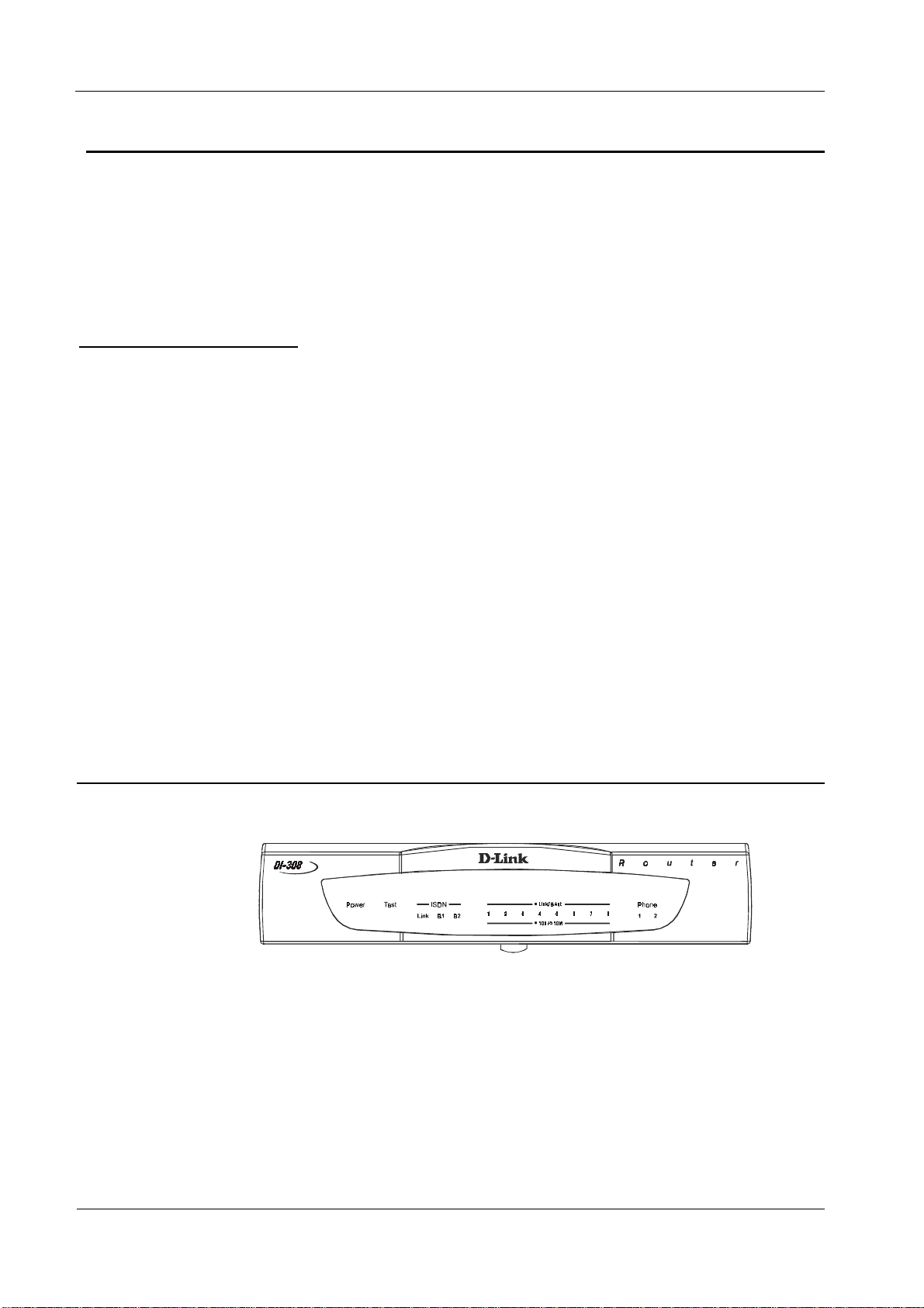
The DI-308 Front Panel
Names and descriptions of your router’s front panel LEDs are given below:
POWER
plug the power adapter into a suitable AC outlet.
— Comes on as soon as you connect the router to the power adapter and
TEST
ISDN – LINK
interface and it has been successfully initialized.
ISDN – B1
channel is making or receiving a call.
— Should be blinking if the router is functioning properly.
— Indicates that the router has an ISDN line connected to the ISDN
and
— On if there is an active ISDN session on that channel or if that
B2
6
Page 15

DI-308 ISDN Remote Router
LINK/ACT— 1
through 8— These indicators light up when a port is connected to a
powered-on Ethernet/Fast Ethernet station. The LEDs blink when information is
transmitted or received on a port.
100/10M – 1
through 8— These indicators light up when a port is operating at
100Mbps. Otherwise, if this indicator is dark
is lit, then the port is operating at 10Mbps.
PHONE – 1
PHONE – 2
— Lights up when standard phone port 1 is in use.
— Lights up when standard phone port 2 is in use.
The DI-308 Rear Panel
POWER
included with the router has been lost or misplaced, please ensure that the
replacement adapter meets both the voltage and amperage requirements.
— This socket is an 18 volt, 750mA power input jack. If the power adapter
and
the corresponding
LINK
indicator
CONSOLE
– This 9-pin RS-232 port is used for connecting a console or PC
running a terminal emulation program. It provides out-of-band management
capabilities for the initial setup and configuration of the router.
PHONE 1
and 2 – These normal telephone jacks can be used to connect telephones
or fax machines to the router for use over the ISDN lines. Plug telephone devices
into these jacks as you normally would into a telephone wall socket.
– This socket is used to connect the ISDN line to either an NT-1 or directly to
ISDN
the ISDN wall jack, depending on the type of service delivered by your phone
company.
ETHERNET
– The eight Ethernet ports function as a normal, dual speed NWay
Ethernet switch.
Uplink
•
– This port is used to connect the router to another switch or hub
using a straight-through twisted-pair cable. When the Uplink port is used,
Port 1x is unavailable.
Ports 1x to 8x
•
– These eight ports can be used to connect end-stations to
the router using straight-through cables.
7
Page 16

DI-308 ISDN Remote Router
Telephone Features
Up to two telephones can be attached to the DI-308 router via the Phone 1 and
Phone 2 telephone jacks located on the rear of the router. The router enables the
attached telephones to have a number of features which may or may not be found on
normal telephones and are described below. Additional features, which must be
configured, are described in the
of this manual.
Interface Configuration
–
ISDN
submenu section
• Hold
– This feature is very similar with and can work in conjunction with call
waiting as defined in the
Interface Configuration
this manual. Press Flash 0 to place someone on hold (
–
ISDN
Flash
is a very brief
submenu section of
hanging up of the phone). Press Flash 2 to take the caller off hold.
• Hold (and pick up from another location)
- Telephones connected to the router
can be put on hold by pressing Flash 71, 72, 73, or 74. Press the same number to
take the caller off hold and speak from another phone on your telephone network.
• Call forwarding
– If you wish to forward incoming calls to a different telephone,
press *77* and then the phone number you wish to forward the call to. All
incoming calls will automatically be forwarded to the phone number entered.
Press #77# to cancel call forwarding.
• Three-person conference call
– To use this feature, conference calling must be
enabled by the telephone company. After this is done, pick up a phone and place a
call. After connected, press Flash 0 (refer to
Configuration
–
ISDN
submenu section of this manual) and dial the second
call waiting
in the
Interface
number. After connected, press flash 3 to speak to both parties at the same time.
Press Flash 0 to hang up with the first party called. Press flash 1 to hang up with
the second party called.
• Call transfer
– To transfer a call to the other phone jack on the router: if using
Phone 1, press flash 20. If using Phone 2, press flash 10.
Installation and Initial Configuration
This section discusses the different connections that can be made to the router when
setting it up.
Initially, you will only wish to connect the console to the router in order to configure
the other ports. Once that is complete, you will need to turn off the power to the
router and plug in the connection cables to the other devices. Next, power on the
other devices. When they have finished powering up, power on the router. Each of
these steps is described in detail in the sections below. Please skip any setting
adjustments that do not apply to your configuration needs.
8
Page 17

For the initial configuration of your DI-308, you must use an RS-232 console
connection, either to a computer running serial communications software or to a
serial data terminal.
After the router has been successfully installed and the initial configuration is
complete, you can continue to modify settings through the console, or you can
change configuration settings through a remote Telnet connection or through a Webbased configuration utilization program. See the chapters entitled “
and Management”
and “
configure your DI-308.
A Warning on Connection Cables
ISDN and Ethernet cables are very similar to each other. It is important that you use
the correct cable for each connection; otherwise, your router could be damaged.
Before connecting or disconnecting an RS-232 cable between two devices, turn both
devices off to avoid any chance of damaging them.
Using Telnet”
DI-308 ISDN Remote Router
Configuration
for detailed instructions on using Telnet to
Step 1 - Setting up the Console
The initial setup of the DI-308, requires connecting a console to the 9-pin RS-232
Diagnostic port on the router’s rear panel. A serial cable is supplied with the
router in order to make this connection. A console can be a terminal, such as a
VT-100, or a normal PC running terminal emulation software (such as Microsoft
HyperTerminal, included with Windows). The terminal emulation software needs
to be configured to the following parameters:
VT100 terminal emulation
◊
9600 baud
◊
No parity, 8 data bits, 1 stop bit
◊
No flow control
◊
Step 2 - Connecting the Console to the Router
A serial cable is included in the DI-308 package. To connect this cable, plug its ninepin connector into the 9-pin RS-232 Diagnostic port on the router’s rear panel, then
connect the other end to the serial port on the rear of your computer or data terminal.
Please make sure both machines are turned off before making this connection.
After the connection is made, first power on the console. If you are using a PC, run
the terminal emulation software at this time. After the PC and the terminal emulation
software are up and running, power on the router.
9
Page 18

DI-308 ISDN Remote Router
Using the Console
The Console Program is the interface that you will be using to configure your
DI-308. Several operations that you should be familiar with before you attempt to
modify the configuration of your router are listed below:
• Moving the Cursor -
Within a menu, use tab and arrow keys to navigate
through different information fields.
• Moving Forward to Another Menu
the current one, use tab or arrow keys to position the cursor on the submenu
item and press <Enter> to view the selected submenu.
• Entering Information -
There are two types of fields that you will need to fill
in. The first requires you to type in the appropriate information. The second
gives you choices to choose from. In the second case, press the space bar to
cycle through the available choices. Upon configuring all fields the submenu,
position the cursor on SAVE and press <Enter> to save, or position the cursor
on EXIT to cancel.
• Refresh Screen -
Console screens are notorious for becoming garbled. When
this happens, simply press <Ctrl> + <R> to refresh the contents of the screen.
Step 3 - Connecting an ISDN Line to the Router
Your phone company will provide an S/T interface into your home or office. Plug
the ISDN line from the router directly into the ISDN wall socket provided by your
phone company.
- To move forward to a submenu below
Step 4 - Connecting a Telephone or Fax Machine to the Router
You can connect a regular telephone, fax machine, or modem to your router to be
used for analog calls. Note that the router’s other functions all work the same
whether you connect an analog device or not.
To connect an analog device, just plug one end of the device’s cord into one of the
sockets on the back of the router marked PHONE 1 or PHONE 2.
To have incoming calls directed to a device on a PHONE jack, you must enter the
telephone number for the phone in the console program under the
Configuration, ISDN
submenu.
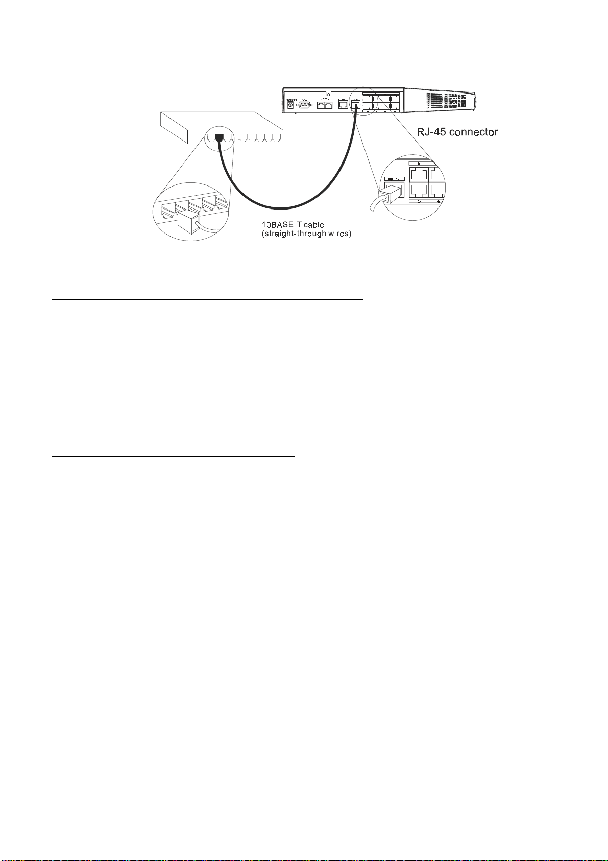
Step 5 - Connecting Ethernet Cables to the Router
Your DI-308 has eight ports for connecting Ethernet devices to form a LAN. The
jacks for ports 1 through 8 are wired to let you connect network end nodes
(computers, servers, bridges, other routers, etc.) using up to 100M of standard
“straight-through” Category 5 UTP cable. In addition, an Uplink jack is wired to let
you connect to another Ethernet or dual-speed switch using a straight-through cable,
Interface
10
Page 19
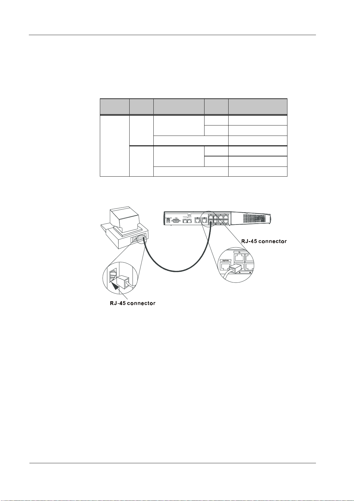
DI-308 ISDN Remote Router
or an end node using a cross-wired cable. Please note that when the Uplink port is in
use, Port 1x is unavailable.
Please refer to the following chart when deciding on the type of cable necessary for a
given connection:
DEVICE PORT
USED
Normal
Router Server (or PC) Straight-Through (||)
Uplink
DEVICE BEING
CONNECTED
Hub or
Switch
Hub or
Switch
Server (or PC) Crossover (X)
PORT
TYPE
Normal Crossover (X)
Uplink Straight-Through (||)
Normal Straight-Through (||)
Uplink Crossover (X)
CABLE TO USE
The figure below shows how to make an Ethernet connection between the router and
a network end node.
Important Notes on Ethernet Connections
Observe the following rules when connecting devices with twisted-pair Ethernet
cables:
For both end-node and uplink connections, use only EIA Category 5 UTP
•
cables with RJ-45 plugs.
Make sure no cable is more than 100 meters (328 feet) long.
•
When uplinking two hubs together with a straight-through cable, use an
•
uplink-type jack at one end, and an end-node-type jack at the other.
This is the maximum signal path in twisted-pair Ethernet. Also be sure never
•
to allow a signal loop to form.
11
Page 20
DI-308 ISDN Remote Router
Note that you can connect an end node through the Uplink jack, but to do so
you must use a cross-wired cable or cable converter.
Step 6 - Powering Up Devices for Initial Configuration
Plug in the included 18V DC, 2.5A power adapter into the power jack on the
router’s rear panel.
You should have now connected the RS-232 cable to the console, the ISDN phone
line, one or more Ethernet cables, and the power adapter.
At this point in the installation process you can now power up the console computer,
run the terminal emulation software (if necessary), and then power up the DI-308.
Step 7 - Initial Configuration of the Router
After the console is properly connected and both devices are powered on as
described in the preceding sections, you should see the router run through the power
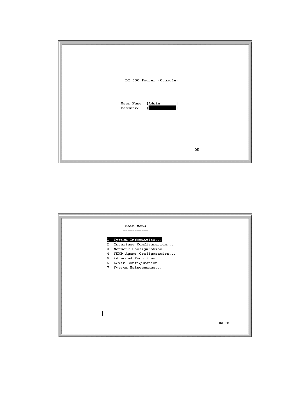
on self test (POST). Finally, it will arrive at the logon screen shown below. If the
login screen does not appear, press <Ctrl> + <R> to refresh the screen.
12
Page 21
DI-308 ISDN Remote Router
To log on to the router, use the factory set username and password ‘Admin’ (without
the quotes). Please note that the user name and password are case-sensitive.
Upon entering the username and password (using the tab key to jump to the next
field), position the cursor on OK and press <Enter>. You will then see the following
Main Menu
:
13
Page 22

DI-308 ISDN Remote Router
Step 8 - Configuring the LAN Port
Preparing the router for connection to a LAN only requires enabling the LAN port,
enabling IP networking, assigning the LAN port an IP address and enabling telnet (if
necessary). After the LAN port is configured, all other features on the router can be
configured remotely through the LAN by using the included Windows-based Router
Configuration Utility or Telnet. Regardless, the router can always be configured
using a console connected to the RS-232 Console port.
To configure the LAN:
1. The LAN port must be enabled in the
Choose
•
Position the cursor over the State item and press <space bar>.
•
Position the cursor on the Save option at the bottom of the screen and press
•
Interface Configuration, LAN.
Interface Configuration
submenu.
<Enter> to save the new setting.
Choose Exit in the submenus to return to the
•
Main Menu
.
2. Enable IP Networking
Choose
•
Position the cursor over the last item IP Networking and press <space bar> to
•
Network Configuration, IP Configuration.
enable it.
Position the cursor on the Save option at the bottom of the screen and press
•
<Enter> to save the new setting.
3. Assign an IP address to the LAN port in the
the
Main Menu
.
Network Configuration
submenu of
Still in
•
above, choose
Enter a valid IP address for the LAN in the first item. You may also enter a
•
Network Configuration, IP Configuration
IP Stack Configuration, LAN.
submenu from Step 2
Netmask if you wish. For more information about IP Addresses and Subnet
masks, please refer to Appendix B,
Position the cursor on the Save option at the bottom of the screen and press
•
“IP Concepts
.”
<Enter> to save the new setting.
Choose Exit in the submenus to return to the
•
Main Menu
.
4. Enable the Telnet/Discovery function on the router.
From the
•
Main Menu
choose
14
Advanced Functions
.
Page 23

Choose the Telnet/Discovery Enable option to enable Telnet if it has not been
•
done so already.
Position the cursor on the Save option at the bottom of the screen and press
•
<Enter> to save the new settings.
Choose Exit in the submenus to return to the
•
The router can now be accessed via the LAN by Telnet, the Web-based DI-308
Router Configuration Utility (included with the router) and other SNMP
management applications.
If you have any questions regarding the settings you made or other settings in the
submenus, please refer to the next chapter, “
Step 9 – Plugging in All Devices
You can now plug in and power on all other devices connected to the router. Then
power on the router.
DI-308 ISDN Remote Router
Main Menu
.
Configuration and Management
.”
The router is now able to use the LAN ports.
The router must be further configured in order to get the built-in ISDN modem to
function properly, to perform other routing functions, and to manage your IP
network. This can now be done by using the console, the included Web-based
Configuration Utility or Telnet.
For more information about configuring or managing the router, please refer to the
next chapter, “
Configuration and Management
.”
15
Page 24

DI-308 ISDN Remote Router
Configuration and Management
After the initial startup (POST) test, the router will prompt you for login and
password. This is the opening page of the router’s out-of-band configuration
program, called the Console program. The Console program is stored in the Flash
memory chips in the router and the settings are written in EEPROM chips in the
router. It is the most basic level for configuring and managing the router and the
network to which it is connected.
If you’re starting the router for the first time, the default login and password is
“Admin” – the login and password are case-sensitive, alphanumeric characters.
Note that once you are in the
minutes, the router will automatically log you out. Your first endeavor should be to
increase the ‘timeout’ time by adjusting the appropriate value in the
Information
The router can also be configured remotely by using the included Router
Configuration Utility or through Telnet. However, if you wish to do this, the console
program must first be used to initially configure the relevant port on the router.
Please see
more detailed information.
submenu.
Step 7 - Initial Configuration of the Router
Console Program Main Menu
Main Menu
16
, if there is no activity for more than 5
System
on page 12 of this manual for
Page 25
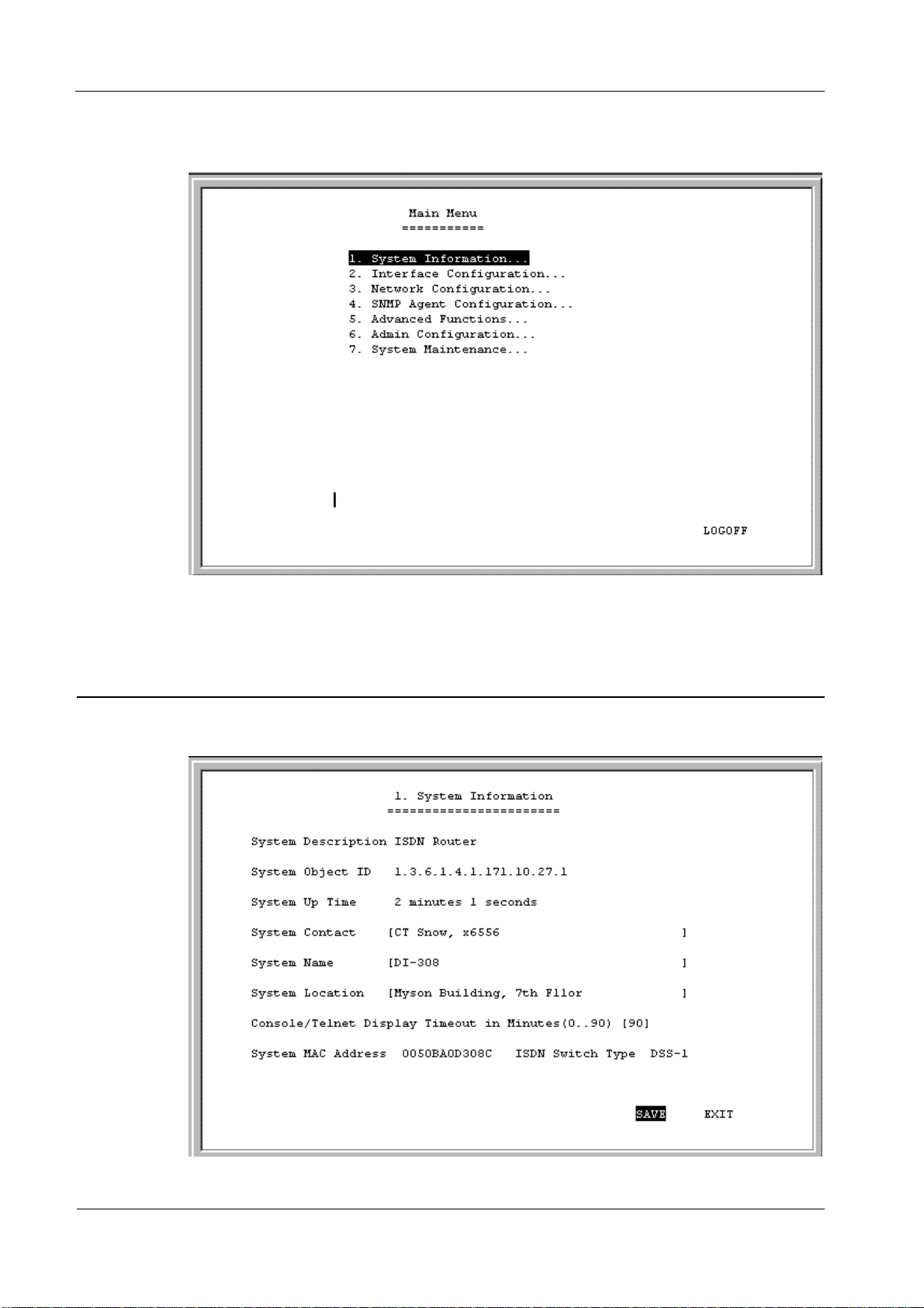
DI-308 ISDN Remote Router
The
Main Menu
is shown below:
As mentioned earlier, your first endeavor should be to increase the automatic
timeout. Enter the
System Information
This menu contains administrative and system-related information.
System Information
submenu to do this.
The above parameters are described as follows:
17
Page 26
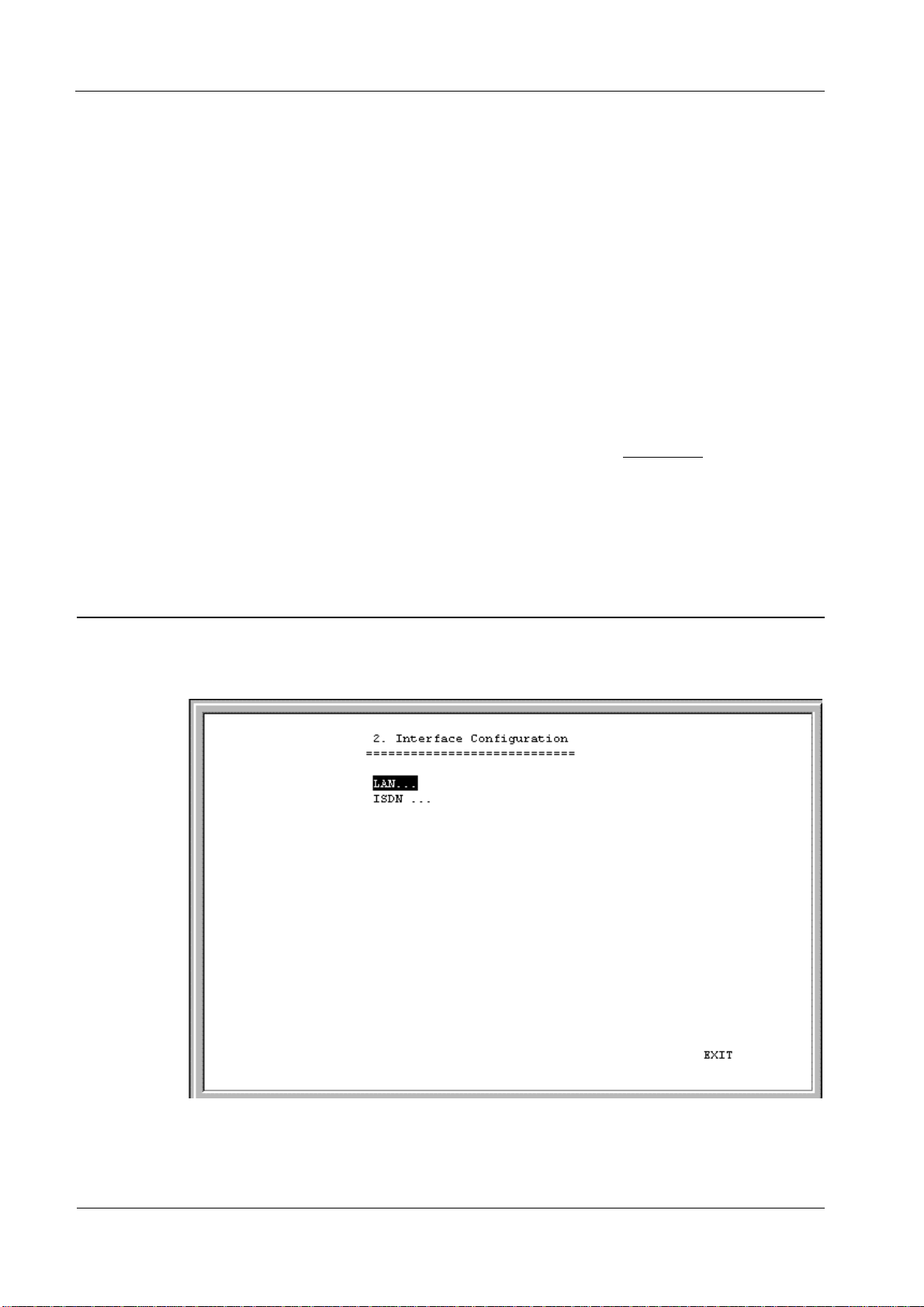
DI-308 ISDN Remote Router
• System Description –
• System Object ID –
This is a non-changeable, short description of the product.
This is the enterprise-specific MIB Object ID indicating this
type of router.
• System Up Time –
Shows how long the router has been running since the last
power on or reset.
• System Contact –
Enter the name of the department or individual responsible for
maintaining the router.
• System Name –
• System Location –
• Console/Telnet Display Timeout in Minutes –
Give the router a descriptive name for identification purposes.
Enter the geographic location of the router.
This is a security measure to
automatically logoff from the console menu after a given idle time. Enter a
timeout time between 0 and 90 minutes. Zero specifies no timeout.
• System MAC Address –
• ISDN Switch Type
The physical address of this router.
– The type of ISDN switch used by the telephone company
that the DI-308 can communicate with. The DI-308 currently supports only the
DSS-1 switch type.
Interface Configuration
Under
configuration screen, used to configure the LAN and ISDN interfaces:
Interface Configuration
in the main menu is the following interface
18
Page 27

LAN
DI-308 ISDN Remote Router
The parameters are described below:
• Description –
This is a user-defined, 32-character identifier used to name the
LAN.
• Operation Mode –
• State –
This is a toggle to
The LAN port is Auto Negotiation only.
Enable
or
Disable
the LAN interface.
19
Page 28
DI-308 ISDN Remote Router
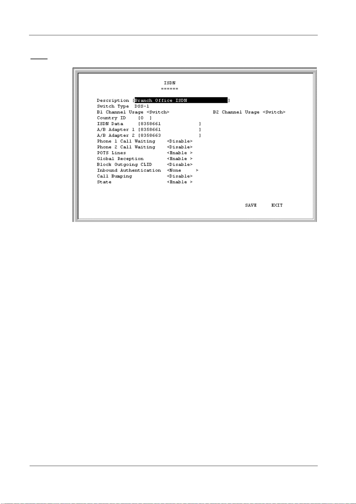
ISDN
The parameters are described below:
• Description –
This is a user-defined, 32-character identifier used to name the
ISDN.
• Switch Type –
This parameter defines the type of ISDN service used. Currently,
the DI-308 only supports DSS-1 type ISDN lines.
• B1
and
B2 Channel Usage –
This defines whether the ISDN line is a leased line
or a normal switched line. If you are not using a leased line connection, set this
item to Switch.
• Country ID –
This field needs to contain the country parameter. Without this
information, the router cannot establish a connection. A list of country ID
numbers is located in Appendix E,
• ISDN Data –
This field must contain the incoming telephone number for data
“Country ID Numbers
.”
calls. In other words, it is your ISDN line’s data phone number.
• A/B Adapter 1
• Phone 1
and
and 2 – Enter the telephone numbers for your voice/analog lines.
2 Call Waiting
– If you have applied for and received call waiting
capabilities for your ISDN voice lines, you must enable these settings in order for
the call waiting feature to function.
There are four special operations for using call waiting (
flash
means a very brief
hanging up of the phone. In other words, for the first option below, flash 0, click
the hang up button on your phone very quickly and then press the number 0 on
your telephone’s keypad):
20
Page 29

DI-308 ISDN Remote Router
Flash 0 – disconnect the first phone call established.
Flash 1 – disconnect the second phone call established.
Flash 2 – switch between the two phone calls.
Flash 3 – speak to both parties simultaneously (if conference calling is enabled by
your phone company).
• POTS Lines
– [Plain Old Telephone Service]. Enables or disables phone calls on
the Phone 1 and Phone 2 jacks on the rear of the router.
• Global Reception
– When this is enabled, the Phone 1 and Phone 2 jacks will
receive all phone calls directed to them by the telephone company’s switch. When
disabled, the router will check incoming calls to the Phone 1 and 2 jacks against
the telephone numbers specified in the A/B Adapter 1 and 2 fields above.
• Block Outgoing CLID
– When this is enabled, your ISDN data phone number
and voice phone numbers will never be sent out when trying to establish a
connection. Thus, even if sites being called have Caller ID, they still won’t be
able to know your phone number.
• Inbound Authentication
– This defines the authorization protocol that will be
used when accepting a dial-in connection. The choices are Password
Authentication Protocol [
CHAP
[
None. PAP
] or
PAP
and
], Challenge Handshake Authentication Protocol
CHAP
do not provide a screen for users to manually
enter their Username and Password – instead, this data must be entered into the
dialing software before placing the call. Make sure the device dialing in is using
the same protocol as defined here. The
None
setting may be used when you do not
wish dial-in users or networks to identify themselves or be subject to security.
• Call Bumping
– This setting only takes effect when both B channels are
connected and using multi-link PPP. If this is the case and call bumping is
enabled, when you receive an outgoing voice call, the second B channel will be
dropped (with all traffic being moved to the first B channel) and the voice call
will be received. If disabled, both B channels will continue their data
transmissions uninterrupted and the voice call will be ignored.
• State
– Enables or disables the ISDN port.
Network Configuration
There is one main item on the DI-308
Network Configuration
menu:
21
Page 30
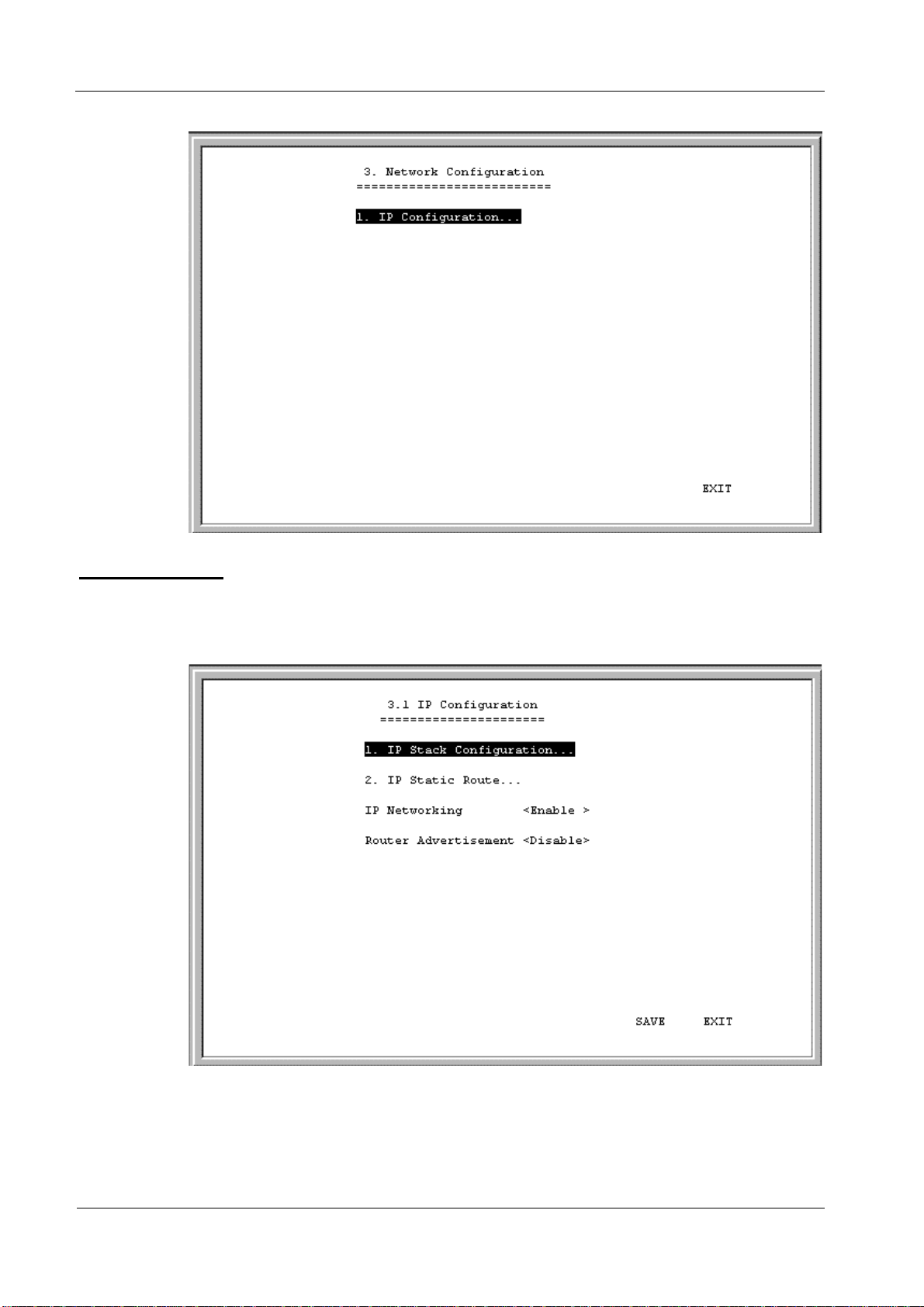
DI-308 ISDN Remote Router
IP Configuration
IP protocol configuration and static routes are configured in the
submenu. This menu is shown below:
IP Configuration
IP Stack Configuration
The network interface IP address, mask and protocols are specified in the
Configuration
IP Stack
submenus.
22
Page 31

DI-308 ISDN Remote Router
Below, the submenus for both the LAN and ISDN interfaces are shown:
23
Page 32

DI-308 ISDN Remote Router
The parameters are described below:
• IP Address –
This is the IP address for the router on the network to which this
interface is connected.
• Netmask –
This is a 32-bit bit mask that shows how the IP address is to be
divided into network, subnet and host parts. The netmask has ones in the bit
positions in the 32-bit address which are to be used for the network and subnet
parts, and zeros for the host part. The mask should contain at least the standard
network portion (as determined by the address's class), and the subnet field
should be contiguous with the network portion.
• Forwarding (LAN) –
This enables or disables forwarding between or among
interface(s).
• State (ISDN) –
This is a link method between this interface and adjacent
router(s). The methods are described:
Auto –
1.
This obtains and utilizes the IP address assignment from your ISP
(Internet Service Provider).
Disable –
2.
IP Stack –
3.
This disables this interface.
This enables this interface, and the IP address used will be the
value of the parameter, IP Address.
Unnumber –
4.
This utilizes a method of connecting this router with adjacent
routers, without having to define an IP network prefix between them. The
adjacent routers must have
• Routing Protocol –
This is a distance vector routing protocol. RIP is an Internet
UNNUMBER
capability too.
standard Interior Gateway Protocol defined in RFC 1058 and RFC 1723. Routing
information is sent periodically (each 30 seconds, or triggered by topology
24
Page 33

DI-308 ISDN Remote Router
change) to an adjacent router. The adjacent router must be using the same
protocol. Setting this to
RIPV1&V2
will give the router the ability to make
routing information exchanges with any adjacent router.
• Routing Mode
– This parameter allows the router to specify the extent to which
it partakes in the RIP on this port. The options are described below:
None
1.
– The router will not participate in any RIP exchange with adjacent
routers.
Listen
2.
– The router will incorporate routing information from adjacent routers,
but will not send its own routing table.
Talk
3.
– The router will send adjacent routers its own routing table, but will not
incorporate routing information from them.
Both
4.
– The router will incorporate routing information from adjacent routers,
and will send adjacent routers it’s own routing table.
• IP Multicasting –
This feature enables or disables the router’s ability to route IP
Multicast packets from one interface to another (for example, from the LAN ports
to the ISDN port). IP Multicasting is a bandwidth-saving method for transmitting
data to more than one host. IP Multicasting is often used when sending/receiving
audio or video data. When IP Multicasting is enabled, the router will search its
multicast forwarding table and depending on the result of the search will either
forward the packet or add the group to the table. If IP Multicasting is disabled, all
multicast packets received by the router will be dropped, effectively limiting
multicasting to the LAN. The router can also perform DVMRP if this feature is
enabled (see Multicast Protocol below), which allows the DI-308 to share
multicast information with other routers, enabling IP multicasting over the ISDN
port.
• Multicast Protocol –
If this parameter is set to
None
, the router will only use the
Internet Group Management Protocol (IGMP), if IP Multicasting is enabled
above. This effectively limits multicast data to the local network. If set to
DVMRP
(Distance Vector Multicast Routing Protocol), the router will also use
this protocol to share its multicast information with other routers (much like RIP),
in effect, enabling multicasting on the WAN (ISDN) port.
• IGMP Version –
Configures the router to use either IGMP version 1 or 2. A
major difference between the two is that version 2 allows the router to
communicate multicast information with other routers (via the ISDN port), even
if the other router isn’t using DVMRP.
• DHCP Client (LAN)
– This feature allows the LAN port to be assigned an IP
address from a DHCP server other than the one in the router. This feature should
be enabled only for special configurations (such as the presence of a cable modem
on the LAN) where you wish the router to work with a device on the network that
must act as a DHCP server. Otherwise, this feature should be kept disabled.
• RIP Spoofing (ISDN)
– This feature should only be enabled if you have more
than one router on your network and this router is providing your WAN
connection. In this case, if the WAN connection is dropped due to inactivity and
25
Page 34

DI-308 ISDN Remote Router
IP Static Route
A static route is a permanent entry in the routing table. Static routing provides a
means of explicitly defining the next hop router for a particular destination network
IP address. Each static route entry also allows for a metric (a.k.a. hop count) to be
specified.
this feature is enabled, RIP packets will be sent to the other routers on the
network telling them that data can still be sent to the WAN via this router.
Otherwise, the other routers will learn that the WAN link has been disconnected
and will no longer forward packets destined for the WAN to this router, causing
the packets to be dropped before Bandwidth on Demand has a chance to
reestablish the WAN connection.
The parameters are described below:
• IP Address
– This specifies the destination network IP address (or a host,
depending on the netmask) and pairs it with a gateway.
• Netmask
– This mask shows how the destination IP address is to be divided into
network, subnet and host parts. The netmask has ones in the bit positions in the
32-bit address which are to be used for the network and subnet parts, and zeros
for the host part.
• Gateway
– This is the adjacent next hop router, for which the packets, arriving to
this router with this destination IP address, will be forwarded.
• Hops
– This is an associated RIP metric that may have its value set between 1
and 15, inclusive. A metric value higher than 15 (such as 16) means that the
network is unreachable.
26
Page 35

DI-308 ISDN Remote Router
• Intf
– This is the network interface containing the gateway that the packets will
be forwarded through.
• State
IP Static Route Examples
– This enables or disables a particular entry.
The IP Static Route Table shown in the example IP Static Route screen above has
the first three entries configured for common implementations of static routing.
The first entry assumes that ISDN1 has a connection to the Internet and defines the
default next hop router. If you use this router to connect to the Internet it is very
important that you create an entry here that defines the default next hop router as
your ISP. This configuration is also commonly used when RIP exchanges with other
Internet routers (on ISDN1) are disabled.
The second entry shows how to configure static routes when there is another router
on the LAN. The IP Address shown (202.12.125.0) is the network address for a
branch office, for example. The Gateway Address (210.172.23.1) is the IP address to
the LAN port on another router on the LAN that maintains an ISDN connection to
the branch office.
The third entry is an example of an enterprise ISDN connection (through telephone
lines) to another router, at a branch office for example. The IP Address is the
network address of the branch office. The Gateway Address is the IP Address of the
ISDN port on the branch office router. This configuration assumes there is a modem
on ISDN2 maintaining a dial-up connection to the branch office.
IP Networking
Under the
connect/disconnect this router from the entire IP network.
When IP Networking is disabled, all routing functions are stopped. The only IP
Address the router will act on is its own, via Telnet for example.
Router Advertisement
When this option is enabled, the router will periodically send out ICMP packets that
announce itself on the network. These ICMP packets are utilized by the Windows 98
or later operating system, which will automatically update the default gateway
setting on the computer in which it is installed.
IP Configuration
submenu, the IP Networking function can toggle to
SNMP Agent Configuration
The Simple Network Management Protocol (SNMP), defined in STD 15, RFC 1157,
is a protocol governing the management and the monitoring of IP network devices
and their functions. The DI-308 supports the use of SNMP to acknowledge
communication between management stations and itself. Basically, the DI-308,
27
Page 36

DI-308 ISDN Remote Router
when connected to the network, acts as an SNMP agent, a software process that
responds to queries using SNMP to provide status and statistics about the router.
Following is a description of how to configure the DI-308 for SNMP management.
From the
the
Main Menu
SNMP Agent Configuration
SNMP Community Configuration
Select and enter the
SNMP Community Configuration
following configuration screen:
, select
SNMP Agent Configuration
menu, shown above.
submenu. You will see the
. This will bring you to
28
Page 37

DI-308 ISDN Remote Router
The parameters are described below:
• SNMP Community String
name used to group together some arbitrary set of SNMP application entities
managed by the network manager.
• Access Right
SNMP access mode. If the SNMP Community String has an Access Right of
Read/Write
set
, and
Access Right is
next
operations only.
• Status
setting the string to
Invalid
validated at an appropriate time.
SNMP Trap Manager
From the
Manager
– This community string is a user-defined identifying
– This element of the set {
, then that Community String is available as an operand for the
get next
operations. Otherwise, if the Community String’s corresponding
Read Only
, then it is available as an operand for the
Read Only, Read/Write
} is called the
get
get
and
,
get
– This validates or invalidates the use SNMP Community String, by
Valid
or
Invalid
. Note that setting the use of the string to
is the same as removing the string, however, the string remains so as to be
SNMP Agent Configuration
menu, select and enter the
SNMP Trap
submenu. You will see the following configuration screen:
29
Page 38

DI-308 ISDN Remote Router
The parameters are described below:
• IP Address –
Management Station. The DI-308 router will send SNMP traps to these addresses.
• SNMP Community String –
name used to group together some arbitrary set of SNMP application entities
managed by the network manager. Traps will be sent to the IP Address (previous
parameter) as long as the corresponding Community String, in the Management
Station’s trap manager software, is the same.
• State –
This validates or invalidates the use of the SNMP Community String, by
setting the use of the string to
Invalid
is the same as removing the string, however, the string remains so as to be
validated again at an appropriate time.
SNMP Authenticated Trap
Returning to the
authentication failure trap message being sent to the Management Station by the
router. When an SNMP packet with an invalid community name is received, it will
be dropped. If this parameter is enabled, a trap will be sent to the network manager;
if this parameter is disabled, no trap will be sent.
Enter the IP address of the host who will act as an SNMP
The community string is a user-defined identifying
Valid
SNMP Agent Configuration
or
Invalid
. Note that setting the string to
menu, you can
Enable
or
Disable
an
Advanced Functions
The
Advanced Functions
settings and is shown below:
menu contains most of the more complex configuration
30
Page 39

DI-308 ISDN Remote Router
Remote Access Configuration
The
Remote Access Configuration
dial-out connections over the ISDN line. An ISDN line has a D channel for
establishing connections and two B (Bearer) channels, which transmit and receive
the actual signals, whether voice or data. The two B channels can support two
independent remote connections or be banded together using Multi-link PPP to
implement Bandwidth on Demand (configured separately in the
Configuration
menu, the last item in the
The B-Channels can also carry voice and fax calls, which are routed to the telephone
jacks located on the rear of the router. Please note, however, that the DI-308 can
maintain only two connections at a time via the two B channels, whether the
connections are voice, data, dial-in users, remote networks or a combination thereof.
menu is used to set up the router for dial-in and
Multi-Link PPP
Advanced Functions
window).
31
Page 40

DI-308 ISDN Remote Router
Remote Operation Overview
The DI-308 is very flexible and can be configured for a variety of remote
connections. Since configuring the router can be quite complex - depending on the
number and type of remote connection(s) you wish to implement – we have
described some of the basic functions and procedures below.
Dial-In User Connections
Dial-in users are defined as a single user on a computer, such as a person working at
home, who dials into the office to use network resources. In almost all cases, a DialIn User Profile needs to be set up for each user who will dial in to the router so the
router can tailor the connection for each user. Once this is done, the remote user will
be able to use network resources as if he were connected locally. When the user dials
into the DI-308, the call comes into the D-channel and after answering the phone, the
DI-308:
1. Identifies the Username and Password using the authentication protocol defined in the
Configuration, ISDN
enter it into his dialing software before dialing.
2. Checks the Username and Password against those defined in the Dial-In User Profiles and Remote
Network Profiles.
3. Assuming a matching Dial-In User Profile is found, the router may configure the IP a ddress of the
remote station (as defined in the Dial-In User Profile).
4. Configures a dial-in Interface (a virtual circuit) to handle the connection.
5. Establishes the connection on whichever B-channel (p hysical port) is open by mapping the di al-in
interface to that port.
6. In the case where the Dial-In User does not need to supply a Username and Password (Auth Type
is set to
IP address.
None
in the
submenu. The dial-in user is not prompted for this information, but must
Interface Configuration
Remote Network Connections
Remote networks are defined as other networks (LANs) that have WAN connections
using a router, Internet server, network modem or similar device (in this document
however, we will assume the remote device is a router). In almost all cases, a
Remote Network Profile needs to be set up for each network that will connect to the
DI-308 via the ISDN lines. The Remote Network Profiles are necessary for the
router to identify and tailor the connection to the remote network’s router. Once this
is done, a connection between the two routers can be made and computers on each
network can communicate with each other.
Interface
submenu) the remote computer must have its own
Dial-In Network Connections
A dial-in network connection is very similar to a dial-in user connection. When the
remote router dials into the DI-308, the call comes into the D-channel and after
answering the phone, the DI-308:
1. Identifies the Username and Password using the authentication protocol defined in the
Configuration, ISDN
2. Checks the Username and Password against those defined in the Dial-In User Profiles and Remote
Network Profiles.
submenu.
32
Interface
Page 41

DI-308 ISDN Remote Router
3. Assuming a matching Remote Network P rofile is found, the router may configur e the IP add ress
of the remote station (as defined in the Remote Network Profile).
4. Configures the specified ISDN Interface (a virtual circuit) using the configuration parameters
defined in the
connection.
5. Establishes the connection on whichever B-channel (p hysical port) is open by mapping the di al-in
interface to that port.
Interface Configuration
menu and the Remote Network Profile to handle the
Dial-Out Network Connections
Dial-out network connections are much different than dial-in connections.
When a packet on the LAN reaches the router, the DI-308 will:
1. Check its routing table to try to identify where this packet should go. It looks for two variables in
the routing table, Gateway address and Interface. There are four possible results:
I. In the case where the destination resides in the same IP network on the LAN, the routing
engine never acts on the packet and it is sent directly to the destination through the built-in
switch.
II. In the case where the destination resides on a different IP network on the LAN (which can
happen when Multiple Home Configuration is set up), the router will send out an ARP request
to obtain the MAC address of the destination computer (or router) and deliver the packet. Note
that defining Static ARPs can speed up delivery since the router won’t need to send out an
ARP request.
III. In the case where the router finds a match in the routing table (which includes IP Static
Routes), it uses the Gateway address and Interface numbers to identify the correct Remote
Network Profile to use to dial out. From the Remote Network Profile, the router gets the
telephone number and other information and dials out, establishes a connection and delivers
the packet. If you have a connection to the Internet, it is very important that you define the
default next hop router in the IP Static Routes submenu of the console p rogram as your ISP
(see the
This is because if a user on your LAN makes a request to download a web page for the first
time, for instance, since it is the first time, the DI-308 will not have any record of the web
page’s IP address. If no default next hop router is defined, the request will be dropped and the
user will get a ‘Destination Unreachable’ error message. However, if a default next hop router
is defined on the
request will go through) and the user will receive the web page.
IP Static Routes
IP Static Routes
section of this manual for more detailed configuration information).
screen, the DI-308 will pass this request on to the ISP (the
IV. In the case where there is no match for the destination IP address in the routing table, and no
default next hop router is defined, the packet will be dropped and no action will be taken.
The
Remote Access Configuration
submenu is shown below. All items in the
submenu are described as follows.
33
Page 42

DI-308 ISDN Remote Router
34
Page 43

Dial Configuration
You can configure the two ISDN interfaces on your DI-308 to dial-out only when a
packet is forwarded to that interface, and hang up after all data has been transferred
and the link is idle. This can be used to lower the cost of an unpopular link or used
as a backup link to your ISP. This feature is commonly called “Dial on Demand.”
ISDN interfaces can also be configured here to receive calls from dial in users and
other networks, called “Remote Access.” Please note however, that in all cases, after
configuring the ISDN Links in the
further configured in the
submenu.
Dial Configuration
Dial-In User Profile
submenu, they must be
submenu or
DI-308 ISDN Remote Router
Remote Network Profile
Dial In IP Pool
The dial in IP pool allows you to define a range of IP addresses that will be reserved
for and assigned to dial-in users.
35
Page 44

DI-308 ISDN Remote Router
The items are described as follows:
• IP Address
• Range
ISDN Link 1
This submenu contains a number of settings (shown below) which allow you to
configure the router to dial out.
– This is the first IP Address that will be assigned to a dial-in user.
– This is the number of IP Addresses that can be assigned. In the window
shown above, dial-in users will be assigned the IP Addresses 170.100.200.1 or
170.100.200.2 (only two are necessary since the router used in the examples has
only two ISDN ports).
36
Page 45

DI-308 ISDN Remote Router
The parameters are described below:
• Dial Retry Time –
next dial attempt.
• Dial Retry Count –
router will make when trying to establish a connection on this interface.
• Call Back Delay –
the number designated for a specified dial-in user.
Dial-In User Profile
The
Dial-In User Profile
example a person working at home) to dial in to the router and gain access to the
network. At least one User Profile must be configured for each user who will dial in
(in conjunction with Dial Configuration settings). Please note that WAN connections
to computers on other networks must be defined in the
submenu.
Up to eight users can be set up to dial in to the router. However, more dial-in users
can be accommodated by using a RADIUS server as described in the
Configuration
being used, the Dial-in User Profiles will be disabled.
This is the time (in seconds) the router will wait before the
This is the specified maximum number of dial attempts the
This is the time (in seconds) the router will wait before calling
screen is used to configure the DI-308 for single users (for
Remote Network Profile
RADIUS
section of this manual. Please note that when a RADIUS server is
Highlight one of the eight entries on the
below:
37
Dial-In User Profile
screen displayed
Page 46

DI-308 ISDN Remote Router
Press <Enter> to access the submenu that appears below:
The parameters in the above window are described as follows:
• Name –
The maximum length is 64 characters. This username is for password
challenges (authentication). The user dialing in must supply this username in
order to be allowed access to the router.
• Password –
This is the password associated with the above Name field.
38
Page 47

DI-308 ISDN Remote Router
• Rem CLID
– Remote Caller ID. This is the telephone number of the Remote
User and is used for security. When a phone number is entered in this field, the
router will make sure that the incoming call is coming from the same phone
number as the one defined here. In other words, the remote user can only be
calling from the telephone number defined here, otherwise the call will not be
accepted. This function is disabled if the field is left blank.
• Default IP –
the IP Address Supply setting below is set to
This is the IP address that will be assigned to the dial-in user when
Default
. Assigning an IP address to
the remote computer ensures that the IP address does not clash with other IP
addresses on your network.
• IP Address Supply –
This field defines how the remote user will obtain an IP
address. The choices include:
Default
Dynamic
None
• Call Back –
– Uses the Default IP address defined above,
- Taken from the Dial In IP pool, or
- The remote user supplies their own IP Address.
This field determines if the router will allow call back to the Remote
Dial-In User upon dial-in. If this option is enabled, the router will be able to call
back to the Remote Dial-In User if they request it. In such a case, the router will
disconnect the initial call from this user and dial back to the specified call back
number. The default is no call back.
• Phone Number Supplied by –
• Phone Number –
provided by the person who initially set up the router. If
must enter the phone number that will be called back yourself.
• Idle Time –
packets have gone through the router. This setting will trigger the router to
disconnect this interface when it is reached.
• State –
Enables or disables this User Profile.
Remote Network Profile
The Remote Network Profile is used to configure the router for ISDN connections to
other networks. In practice, the DI-308 will either dial-out to or receive incoming
calls from another router, the ‘gateway’ to the other network.
Highlight one of the eight entries on the
Router
If
Toggle between
Router
is selected above, then this phone number is usually
and
Caller
Caller
.
is selected, you
This is the elapsed time (in seconds) since the last valid or active
Remote Network Profile
screen:
39
Page 48

DI-308 ISDN Remote Router
Press <Enter> to access the submenu that appears below:
• Remote Name
– Name for the remote network that the DI-308 is being set up to
connect with.
• Direction –
Dial-[In], dial-[
Out
], or [
Both
]. This field defines whether the router
on the other network will dial-[In] to the DI-308 to establish a connection, the DI308 will dial-[
Both
[
] ways.
Out
] to the other network, or a connection can be established
40
Page 49

DI-308 ISDN Remote Router
When this is set to In, the DI-308 will only establish a connection with the other
network by receiving calls on the ISDN port specified in the Interface field below.
Also, the incoming calls will be subject to the Name, Password and Rem CLID
fields in the Incoming section below.
When this is set to
Out
, the router will only make calls on the ISDN interface
specified in the Interface field below. Also, the outgoing calls will be subject to
the Name, Password and Phone Number fields in the Outgoing section below.
When set to
Both
, the dial in and dial out conditions described above will both be
observed.
• Interface
– ISDN Link 1 [
ISDN L1
] or ISDN Link 2 [
ISDN L2
]. This field is
used to assign a remote network to a logical (virtual) interface called a virtual
circuit. More than one remote network can be configured to use the same
interface, but they cannot be connected at the same time. Thus, if you wish to
have two WAN connections operate simultaneously, make sure they are
configured on different interfaces. On the other hand, if you have two dial-out
remote network profiles but wish to keep one line always open for dial-in users,
make sure the two dial-out profiles use the same interface. In this case, the two
profiles will share the same interface; the second one using it after the first one’s
idle time has expired and it has relinquished it.
• Phone
– This is the telephone number that will be dialed to make the outgoing
connection.
• Idle Time –
This is the elapsed time (in seconds), of inactivity, that will trigger
the router to disconnect this interface.
• Set Peer IP as default Gateway –
When enabled, this feature sets the IP address
of the remote device as the default gateway (default next hop router) for all
packets not found in the routing table. This option should be enabled for the
ISDN circuit (ISDN1 or ISDN2) that is used to connect to the Internet. Also, if
the Peer IP is set as the default gateway here, you still need to define a static
default route in the
Network Configuration, IP Static Route
submenu, but you
don’t need to designate a gateway IP address for the static route (the routers will
automatically negotiate and adjust the gateway IP setting accordingly). And also
make sure that the Remote IP Address in the Remote Networks Profile is set to
0.0.0.0. Note that only one ISDN circuit should be connected to the Internet, and
only one ISDN circuit (the same one) should be the default gateway.
• Incoming
• Name
– The maximum length is 64 characters. This username is for password
challenges (authentication). The user dialing in must supply this username in
order to be allowed access to the router.
• Password
• Rem CLID
– This is the password associated with the above Name field.
– Remote Caller ID. This is the telephone number of the Remote
User and is used for security. When a phone number is entered in this field, the
router will make sure that the incoming call is coming from the same phone
number as the one defined here. In other words, the remote user can only be
41
Page 50

DI-308 ISDN Remote Router
calling from the telephone number defined here, otherwise the call will not be
accepted. This function is disabled if the field is left blank.
• Call Back –
This field determines whether the router calls back after
receiving a call from this Remote Network Profile. If this option is enabled,
the router will disconnect the initial call and call back to the phone number
that you provide. Note that this field will be valid only if the Direction setting
above is
Both
.
• Outgoing
• Name
– The maximum length is 64 characters. Spaces and punctuation are not
usually accepted. This username is for password challenges (authentication)
which are automatically handled by the router when dialing out. The DI-308
will use PAP and CHAP (whichever works) to make the connection.
• Password
• Remote IP Address
– This is the password associated with the above Name field.
– This is the IP address that will be assigned to the dial-in
network when the IP Address Supply setting below is set to Default. Assigning an
IP address to the router dialing in ensures that the IP address does not clash with
other IP addresses on your network. For dial out connections utilizing dial on
demand, the IP address of the remote router needs to be entered here so the router
knows which remote network to establish a connection with to deliver the packet.
• IP Address Supply
– This field defines how the router will assign an IP address
to a device dialing in. The choices include:
Default
Dynamic
None
• Multi-Link PPP
MLPPP
function. If MLPPP is enabled and BOD is disabled, then both ports will dial up,
establish a direct connection, and combine the bandwidth of the two connections
using the MLPPP protocol. Please note that the DI-308 contains only one MLPPP
bundle.
• Compression
enabled, the router will try to use compression on this remote node whenever
possible. If the destination device is not capable of using Stac compression, the
two devices will still communicate, albeit without using Stac compression. When
disabled, compression will never be used on this remote node.
• State
DHCP Configuration
The DI-308 Router implements the Dynamic Host Configuration Protocol (DHCP),
which allows the entire IP network to be centrally managed by the router. It does this
by assigning IP addresses and configuration parameters to hosts as they are powered
on and come onto the network. This can be a great help for network administration
– Uses the Remote IP address defined above,
- Taken from the Dial In IP pool, or
- The remote user supplies their own IP Address.
– Enables or disables multi-link PPP on this remote node. Both
and
Bandwidth On Demand (BOD) must be enabled for BOD to
– This is an industry standard, 4:1 Stac compression scheme. When
– Enables or disables this Remote Network Profile.
42
Page 51

DI-308 ISDN Remote Router
since many administrative tasks such as keeping track of each computer’s IP address
are handled by the router. The DI-308 can implement DHCP in one of the two ways
shown below:
DHCP Server Configuration
When acting as a DHCP server, the DI-308 will manage many of the IP network
parameters. The DI-308 will never assign a broadcast or network IP addresses to
hosts, even if such an address is included in the specified range.
43
Page 52

DI-308 ISDN Remote Router
Dynamic IP Pool
The
Dynamic IP Pool
screen shown below contains the parameters that the router
can set on the hosts. Please note that the dynamic IP pool cannot be enabled when
the DHCP Agent feature is enabled.
The parameters are described below:
• IP Address –
This is the base (starting) address for the IP pool of IP addresses to
be assigned.
• Range –
This is the range of contiguous, IP addresses, above the base IP Address
above. In the above example, the IP addresses assigned host computers as they
come onto the network would be 202.93.47.1, 202.93.47.2 … 202.93.47.100.
• Netmask –
This mask informs the client, how the destination IP address is to be
divided into network, subnet and host parts. The netmask has ones in the bit
positions in the 32-bit address which are to be used for the network and subnet
parts, and zeros for the host part.
• Gateway –
This specifies the Gateway IP Address that will be assigned to and
used by the DHCP clients.
• Lease Time –
This specifies the number of hours a client can lease an IP address,
from the dynamically allocated IP pool. The maximum value is 65535 and a value
of 0 means the lease is permanent.
• DNS IP –
This specifies the Domain Name System server, used by the DHCP
clients using leased IP addresses, to translate hostnames into IP addresses or viceversa.
44
Page 53

DI-308 ISDN Remote Router
Static IP Pool
• WINS IP –
This specifies the IP address of the Windows Internet Naming
Service server. This server has software that resolves NetBIOS names to IP
addresses.
• Domain Name –
This is the common suffix, shared by networked hosts, used to
represent a common network domain.
• State –
This enables or disables the dynamic IP Pool function.
The Static IP Pool configuration functions in much the same way as the Dynamic IP
Pool configuration. The only difference is that a particular IP address can be
assigned to a particular host. This is used for hosts such as servers that need to have
static IP addresses to function properly or to make them accessible to remote users.
The host is identified by the MAC address of its NIC, which must be entered on this
screen.
Highlight the desired entry on the
Static IP Pool
screen:
Press <Enter> to access the following screen:
45
Page 54

DI-308 ISDN Remote Router
The parameters are described below:
• IP Address –
• MAC Address –
will receive the above IP address.
All other parameters (Netmask, Gateway, DNS IP, WINS IP, State, and Domain
Name) are identical to those in the
previous section.
DHCP Relay Agent
The DHCP Relay Agent feature allows the DI-308 to act as a go-between for a
remote DHCP server assigning IP addresses to local clients. This can be useful if
you wish to have all IP addresses in your company, including those in branch offices,
assigned from a DHCP server centrally located at your headquarters, for example.
This is the static IP address to be assigned.
This specifies the physical address of the particular host that
Dynamic IP Pool Configuration
screen, in the
46
Page 55

DI-308 ISDN Remote Router
Items are described as follows:
• DHCP Server IP Address –
When a local computer powers up and sends a DHCP request for an IP address,
the DI-308 will forward the request to the address specified here.
• Time Threshold –
since the host began requesting an IP address. If the value defined here is
exceeded, the relay agent will not pass along the request from the host.
• State
Filter Configuration
Your DI-308 uses filters (configurable at two layers) to screen packet data, and apply
a routing decision. There are two methods for configuring filters: you can configure
a filter at the network layer (IP filter) to restrict access between networks and reduce
unnecessary internetwork traffic; and you can configure a filter at the data-link layer
(a general filter) to provide a protocol independent filter.
Knowledge of network protocols is required to configure a specific filter
appropriately. It is important for the router to operate correctly, therefore, necessary
packets must be allowed to pass through the filters. In other words, do not attempt to
configure filters on a utilized router unless you understand what you are doing.
This is the IP address of the remote DHCP server.
This specifies the maximum amount of time (in seconds)
– Enables or disables the DHCP Relay Agent function.
The following section describes how to configure the router filter parameters.
Configuring a Filter Set
Under the
Advanced Functions
will see the following screen:
menu, select and enter
47
Filter Configuration
. You
Page 56

DI-308 ISDN Remote Router
The three submenus are described as follows:
• Filter State of Interface
for packets, not meeting the criteria for specific filters.
• Layer 2 Filter
Foreknowledge of the specific protocol, used on the interface (LAN or WANs), is
needed to make effective use of this filter.
• IP Filter
things, prohibit specific packets from entering the LAN. Alternatively, you can
set up filters that allow certain types of IP packets to enter the LAN.
Filter State of Interface
The
Filter State of Interface
the packets are not subjected to a filter, routing decision. In other words, a packet,
having not met the criteria for a specific filter that was applied to a specific interface,
will be subjected to this default, routing decision.
– This is used to choose the default, routing decisions
– This is a data-link layer (protocol independent) filter.
– This is an IP protocol specific filter, allowing you to, among other
submenu lets you toggle default, routing decisions, if
48
Page 57

DI-308 ISDN Remote Router
Layer 2 Filter
Each decision on handling packets is described below:
1.
2.
Disable
Forward
Will not apply a filter.
–
This allows the routing of a packet, even though it has not met the
–
criteria of the corresponding filter.
3.
Drop
This drops (doesn’t allow routing for) a packet that has not met the
–
criteria for the corresponding filter.
The
Layer 2 Filter
submenu contains a protocol independent (data-link layer) filter.
Foreknowledge of the specific protocol used on the interface (LAN or WANs) is
needed to make effective use of this filter.
Highlight the desired entry on the
Layer 2 Filter
screen:
49
Page 58

DI-308 ISDN Remote Router
Press <Enter> to access the following screen:
The parameters of a filter are described below:
• Name –
This is a 12 character (maximum), alphanumeric, user-defined name,
used to identify the filter.
• Direction –
This defines the direction of the frame relative to the Interface
parameter below.
50
Page 59

DI-308 ISDN Remote Router
• State –
This is used to choose the routing decision applied to the frame. The
three decisions are described:
1. Forward
This allows the routing of the frame, if it has met the criteria of the
–
corresponding filter.
2. Drop –
This drops (doesn’t allow routing for) a specific frame that has met
the criteria of the corresponding filter.
3. Disable –
• Interface –
This does not apply the protocol independent filter.
This applies the filter to a specific interface, either LAN or one of the
ISDN interfaces.
• Offset –
This defines the reference byte for the Length parameter (described
below). The Offset is the number of bytes (octets) from the beginning of the first
byte of the frame header, immediately after the preamble. The range of the offset
parameter is from 0 to 255 octets. The first byte in a packet has an offset 0.
• Length –
This is the number of bytes (octets) from 0 to 8 to compare from the
offset value (the Offset reference byte).
• Value –
This is a 16 digit, hexadecimal field, defining the actual bit values used
to compare with the frame data, at the specified (Offset) position.
IP Filter
• Mask –
This is a 16 digit, hexadecimal bit mask, used as an operand in the bit-
wise AND operation that will be applied to the Value parameter.
The IP Filter is specifically an IP protocols filter, allowing you to, among other
things, firewall your network, prohibiting specific packets from entering or going out
from your network. It is necessary to have knowledge of IP protocol before
effectively configuring this filter.
Highlight the desired entry on the
IP Filter
screen:
51
Page 60

DI-308 ISDN Remote Router
Press <Enter> to access the following screen:
The IP Filter parameters are described below:
• Name –
This is a 12 character (maximum), alphanumeric, user-defined name,
used to identify the filter.
• Direction –
This defines the direction of the packet relative to the Interface
parameter below.
52
Page 61

DI-308 ISDN Remote Router
• State –
This is used to define the routing decision applied to the packet. The
three routing decisions are described:
1. Forward
This allows the routing of the packet, if it has met the criteria of
–
the corresponding filter.
2. Drop –
This drops (doesn’t allow routing for) a specific packet that has met
the criteria of the corresponding filter.
3. Disable –
• Interface –
This does not apply the IP filter.
This applies the filter to a specific interface, LAN or one of the ISDN
interfaces.
• Protocol Type –
This is a protocol identifier, as assigned by the Internet
Assigned Numbers Authority (IANA). The values of this identifier are described
in RFC-1700. This router supports the following:
1
- This is Internet Control Message (ICMP), defined in RFC 792.
6
- This is Transmission Control (TCP), defined in RFC 793.
17
- This is User Datagram (UDP), defined in RFC 798.
• Src IP –
This is the source address in the IP header of this packet.
• Src Netmask –
This mask is bit-wise AND’d with the source IP address and bitwise AND’d with the IP address of the incoming interface. The two results are
then compared.
• Src Port –
• Src Port Operation –
This is the source port, in the TCP or UDP header, of the packet.
This comparison operation is applied to the source port
(the Src Port parameter) value, of the TCP or UDP header.
• Dst IP –
• Dst Netmask –
This is the destination address in the IP header of the packet.
This mask is bit-wise AND’d with the destination IP address and
bit-wise AND’d with the IP address of the incoming interface. The two results are
then compared.
• Dst Port –
• Dst Port Operation –
This is the destination port, in the TCP or UDP header, of the packet.
This comparison operation is applied to the destination
port (the Dst Port parameter) value, of the TCP or UDP header.
• ICMP Type –
This is the type field, in the ICMP header, used to identify a
particular ICMP message.
• ICMP Code –
This is the code field, in the ICMP header, used to further specify
the ICMP type.
• TCP Flag –
This is a hex number, representing the six flag bits in the TCP
header. The value range is from 0 to 3F.
53
Page 62

DI-308 ISDN Remote Router
Multiple Home Configuration
Besides the IP address assigned to the LAN interface in the
Network Configuration
menu, the LAN may have up to 3 additional IP interfaces. These additional IP
interfaces are referred to as MIP1 to MIP3. This type of configuration is known as a
multiple home configuration.
Multiple Home can be demonstrated by this example:
A company has 625 users (computers) all connected to one physical network using
Ethernet. However, the company only has one Class C IP network address,
202.100.160.0. This network address will only support 254 users. To solve the
shortage of IP address problem and to plan for future growth, the company applies
for and receives two more Class C IP network addresses, 203.101.161.0 and
204.102.162.0. This gives the company a total of 254 x 3 = 762 IP Addresses, which
it assigns to the computer users, with a few left over for future needs. Due to the
nature of IP networks, however, the users in one IP network domain (202.100.160.0,
for example) cannot communicate with users on a different IP domain
(203.101.161.0). Multiple home solves this problem. When you register the
additional IP network addresses in the
Multiple Home Configuration
menu on the
router, the router will route data between the three IP networks using the single
LAN.
In this router, multiple home configurations only apply to the LAN interface.
54
Page 63

DI-308 ISDN Remote Router
Static ARP
The parameters are described below:
• IP Address
• Routing Protocol
– This is a network IP address of a separate IP network on the LAN.
– This is the same as in the
Network Configuration
section.
Keep in mind that these exchanges are made with adjacent routers on the LAN, if
present.
• IP Multicasting
– This enables or disables IP multicasting on the IP network you
are defining.
All other parameters (Netmask, Routing Mode, Multicast Protocol and IGMP
Version) are identical to those in the
Configuration, ISDN
screens.
Network Configuration, IP Stack
This special function is intended to speed up the process of finding a host's Ethernet
(MAC) address from its network address, and provides a special condition – any
other host acting as an impostor by using the same IP address as the legitimate host,
will be ignored by this router.
Basically, when a packet comes into the router from the ISDN line and is destined
for a host on the LAN, the router will use information defined here to immediately
send the packet to the host rather than send out an ARP request to find the host’s
MAC address.
55
Page 64

DI-308 ISDN Remote Router
Press <Enter> to access the following screen:
The parameters are described as follows:
• IP Address –
This is the IP address of the host you wish to define a static ARP
for.
• MAC Address –
This is the physical address of the host that is the authorized
owner of the IP address.
• State –
This toggles enable or disable.
56
Page 65

NAT Configuration
Network Address Translation (NAT) is a routing protocol that allows your network
to become a
does this by changing the IP address of packets from a
the Internet to a
Internet) and vice-versa.
NAT has two major benefits. First, NAT allows many users to access the Internet
using a small number or even a single global IP address. This can greatly reduce the
costs associated with Internet access and also helps alleviate the current shortage of
Internet IP addresses. Secondly, the NAT process creates a firewall which hides your
local network from Internet users, providing a degree of security to your Internet
connection.
To be successfully implemented, NAT should be used only when the majority of
network traffic remains on the local network. In cases where a large percentage of
network traffic is destined for the Internet, NAT can adversely affect the speed and
performance of your Internet connection. Also, your network servers such as ftp
servers, web servers or mail servers will probably need to be assigned
addresses so their IP addresses remain consistent. This issue will be further
discussed later.
private
local
DI-308 ISDN Remote Router
network that is isolated from, yet connected to the Internet. It
global
IP address usable on
IP address usable on your private network (but not on the
static
NAT IP
Network Address Port Translation (NAPT) is a subset of NAT where many local IP
addresses and their TCP/UDP port numbers are translated to a single global IP
address and it’s TCP/UDP port number. In this document, the term NAT will refer to
both NAT and NAPT unless otherwise stated.
NAT can work in conjunction with DHCP. Thus, if both are enabled and properly
configured, the DHCP server in the DI-308 will assign local IP addresses to
computers on your network.
How NAT Works
In the most common NAT configuration, your network uses local IP addresses that
are not valid on the Internet. Internet (global) IP addresses are unique, with no two
devices have the same IP address. The local IP addresses can be freely assigned to
computers on your network by your network administrator (within guidelines
defined later in this chapter and in Appendix B,
manually or by using DHCP. The ISDN port on the router is assigned a globally
unique IP Address that IS valid on the Internet, since it will be sending and receiving
data directly to the Internet and is therefore part of it. Please study the example
diagram below carefully.
”IP Concepts”
). This can be done
57
Page 66

DI-308 ISDN Remote Router
Router
IP Address
176.220.22.1
ISDN
Port
NAT
Translator
LAN
Port
192.168.100.1
Single
Global
Local IP
WAN
LAN
192.168.100.2
192.168.100.3
192.168.100.4
192.168.100.5
Please note that in the above diagram, the Gateway IP address settings for the local
PC’s needs to be set to 192.168.100.1, the LAN IP address of the router.
NAT manipulates the IP addresses in packet headers on a one-to-one basis. An
outgoing data packet (a packet originating from a computer on the local LAN and
destined for a computer outside the private network) will have its IP address
translated as shown below.
In the Outgoing Data Packet above, the
translated by NAT. The
Destination IP Address
outside the private network, on the Internet for example. And the
Source IP address
is the IP address of a computer
is the IP address that is
Data
portion of the
packet is the information payload borne by the packet, for instance a request to view
a web page.
The router logs the changes made to the IP header in its NAT table. The NAT table
enables the router to send replies back to the local computer as shown below.
In the Inbound Data Packet above, the
is translated by NAT. The
the private network. And the
Source IP Address
Data
Destination IP Address
is the IP address of a computer outside
portion of the packet is the information payload
borne by the packet, for example, the contents of a web page.
58
is the IP address that
Page 67

NAT
DI-308 ISDN Remote Router
The actual information in the NAT table depends whether the router is implementing
NAT or NAPT.
This section discusses the NAT protocol as opposed to NAPT, which is discussed in
the next section.
NAT is the initial protocol set forth by RFC 1631 and provides a means in which
private networks can communicate with the Internet by using a small number of IP
addresses. In our discussion, we will use the example IP addresses listed in the table
below and the network diagram shown on page 58.
Global IP Addresses
(for use with NAT)
200.100.50.1 192.168.100.2
200.100.50.2 192.168.100.3
200.100.50.3 192.168.100.4
200.100.50.4 192.168.100.5
200.100.50.5 192.168.100.6
Local IP Addresses
(assigned to computers
on the local network)
192.168.100.7
192.168.100.8
192.168.100.9
192.168.100.10
Please note that in the above table there are 9 users on the local network using 5
global IP addresses to access the Internet.
When a packet on the local network arrives at the router and needs to be sent to the
Internet, NAT will change the source IP address (for example 192.168.100.2) to a
global address (200.100.50.1, for example). If this packet generates a reply (as for
example, a request to view a web page will), NAT will change the destination IP
address on the reply packet back to the local IP address for delivery to the machine
on the local (stub) network.
The difference between static and dynamic NAT is that once the five global
addresses are manually assigned when using static NAT, they will never change. The
only way to change them is by using the console program to manually reassign them.
When using dynamic NAT, the router will map a local IP address to a global IP
address whenever a request is made. Since there are only 5 global IP addresses in the
example above, there can only be 5 mappings at any one time. In other words, much
like static NAT, only 5 local machines can access the Internet at any one time.
However, contrary to static NAT, the router will discard the mapping between the
global and local IP addresses after a certain length of time (which is quite long so
rarely happens), or after the session is finished (an example of a session is when
requesting a web page, the entire page has completed downloading). The most
common implementation of NAT is to define a range of dynamic addresses to be
used by hosts, but assign static addresses to your servers if you wish for them to be
accessible from outside your network.
59
Page 68

DI-308 ISDN Remote Router
Setting Local IP Addresses
When implementing NAT and thus creating a private network that is isolated from
the Internet, you can assign any IP addresses to host computers without problems.
However, the Internet Assigned Numbers Authority (IANA) has reserved the
following three blocks of IP Addresses specifically for private networks:
It is recommended that you choose local IP addresses for use with NAT from the
private network IP addresses in the above list. For more information on address
assignment, refer to RFC 1597,
1466,
Guidelines for Management of IP Address Space
Class Beginning Address Ending Address
A 10.0.0.0 10.255.255.255
B 172.16.0.0 172.31.255.255
C 192.168.0.0 192.168.255.255
Address Allocation for Private Internets
.
and RFC
NAT/NAPT
The first screen shows the complete NAT table that is defined by the network
manager:
60
Page 69

DI-308 ISDN Remote Router
For any NAT entry, you must configure two different screens. The first one is
accessible by positioning the cursor over the name field and hitting <Enter> (in the
window shown above, this corresponds to the field ‘132’). After configuring the
NAT options in the Name field, you must save the changes, EXIT, and position the
cursor over the NAT IP Pool to configure variables there.
Name Field Configuration Screen
The configuration screen for the name field appears as follows:
61
Page 70

DI-308 ISDN Remote Router
The parameters are described as follows:
• Name –
This is a 12 character, alphanumeric, user-defined name, used to identify
the network address translation.
• Global Interface –
This is the interface corresponding to the Global IP and
Range parameters, in the NAT table, to form unique IP address[es], known to the
outside (regional or Internet) routers, on this interface.
• Local Interface –
This is the interface corresponding to the Local IP and Range
parameters, in the NAT table, to form local IP address[es], known only to this
interface and the network within.
• Translation Mode –
There are five choices, including
None
if no NAT is
desired:
Static NAT
Maps one global IP address to one local IP address. After all
–
global IP addresses are assigned, they will remain static. This option may be
necessary for email, web, ftp servers, etc. where static IP addresses are
essential for operation.
Dynamic NAT
Maps one global IP address to one local IP address. Global
–
IP addresses will be dynamically reassigned to different local IP addresses if
not currently being used. This allows a larger number of users to use a small
number of IP addresses.
Static NAPT
with specific UDP/TCP port numbers enter the local IP domain. The NAPT
map table will not age. This option may be necessary for email, web, ftp
servers, etc. where static port numbers are essential for operation. Setting the
global port number to 0 opens port numbers 1024 to 65535 for the designated
local IP address, creating a
freely accessed by other computers on the Internet, which is necessary for
some applications to function correctly when using NAPT, including
Microsoft NetMeeting, CUSeeMe, etc.
Dynamic NAPT
NAPT map table will age. This option allows many hosts to use a single,
globally unique IP address, and thus will only be used on outbound packets.
• State –
NAT IP Pool Configuration Screen
Enables or disables this NAT configuration.
Now you must select, enter, and configure the NAT IP Pool from the NAT
Configuration submenu, shown below.
Dynamic NAT
One to one mapping of UDP/TCP port numbers to let packets
–
visible computer
One to one mapping of UDP/TCP port numbers. The
-
. This allows a computer to be
This screen (below) is how the NAT IP Pool appears, if
Dynamic NAT
was chosen
for the Translation Mode parameter. Each entry, in this configuration, can be used to
map multiple, contiguous global addresses and local addresses to each other.
62
Page 71

DI-308 ISDN Remote Router
The parameters are described below:
• Global IP –
• Range –
• Local IP –
• Range –
• State –
Dynamic NAPT
This screen (below) is how the NAT IP Pool appears, if
for the Translation Mode parameter. Each entry, in this configuration, can be used to
map a single global address and multiple, contiguous local addresses to each other.
An IP Address that is globally unique and valid on the Internet. It is
the base, global address for the global addresses that will be recognized by the
interface in the Global Interface parameter.
This is the range of contiguous, global addresses above (and including)
the base Global IP.
An IP Address that is only used in the stub domain since it is not
unique. It is the base, local address for the local addresses that will be recognized
by the interface in the Local Interface parameter.
This is the range of contiguous local addresses above (and including) the
base Local IP.
This toggles the enable, disable, for this NAT entry.
Dynamic NAPT
was chosen
63
Page 72

DI-308 ISDN Remote Router
Static NAT
All of the parameters are the same as in
Dynamic NAT
, except the Global IP is a
solitary, global address.
• Global IP
– This is a single, globally unique IP Address of the global interface
(the interface to which it is assigned, in this case, one of the ISDN interfaces) that
is valid on the Internet.
This screen (below) is how the NAT IP Pool appears, if
Static NAT
was chosen for
the Translation Mode parameter. Each entry in this configuration is used to map a
single global IP address a single local IP address.
64
Page 73

DI-308 ISDN Remote Router
Static NAPT
The parameters are described as follows:
• Global IP
– This is a single, global IP Address that is valid on the Internet, or on
the same subnet of the global interface.
• Local IP
This screen (below) is how the NAT IP Pool appears, if
– This is a single, local IP Address that is not valid on the Internet.
Static NAPT
was chosen for
the Translation Mode parameter. Each entry in this configuration can be used to map
a global address and port to a local address and port. Notice that the global address
will be the external IP address of the global interface.
65
Page 74

DI-308 ISDN Remote Router
• Port –
This is a destination port number used by TCP and UDP to de-multiplex
incoming IP packets.
In the above example, incoming packets with the global destination IP Address
(211.11.22.3) and global destination TCP/UDP port (21) will be translated to a
packet with the local destination IP Address (1.1.1.5) and local TCP/UDP port (21).
Port 21 is assigned to FTP servers. Please see Appendix D for more commonly
assigned port numbers, or RFC 1700 for a more complete list.
Configure NAPT for Special Ap[plication]s
Some applications programs that are used over the Internet such as Microsoft
NetMeeting, Diablo, CU See Me and Xwindows send information to a certain port
number or within a specified range of port numbers. The exact port number used is
specific to the application. However, if you find that you are having trouble using an
application over the Internet and you are using NAPT, you may need to exempt
certain port numbers from the NAPT port translation process. Please refer to the user
guide for the program to find out whether it transmits and receives data only through
specified IP port numbers. In order for these programs to work with NAPT, the IP
port numbers required by these applications must be entered in the
NAPT for Special APs
screen shown below.
Configure
66
Page 75

DI-308 ISDN Remote Router
In the above window, position the cursor on any of the numbered name fields and
press <Enter>. This will take you to the NAPT configuration screen for special
applications shown below.
The fields in the above window are described as follows:
• Protocol
–
UDP
or
TCP
. This field designates the type of packets that will be
acted on.
67
Page 76

DI-308 ISDN Remote Router
• Start Port
– Some applications can only send data over a certain range of port
numbers. Thus, all port numbers in the specified range must be exempt from the
NAPT port translation process. This field defines the beginning range of the port
numbers to be exempted from the NAPT port translation process.
• End Port
– This field defines the last port number in the range of numbers
excluded from the NAPT process (see Start Port above).
• Connection Type
OutgoingControl
–
IncomingData
or
. The user must initially
run the special application and send a request to the application server on the
Internet. This outgoing request to join a Diablo server, for example, is used to
trigger the exemption process for the incoming data.
In the example for the game Diablo shown in the above screen, if a packet is sent out
on the TCP port number 6112 (a request by a local user to a Diablo server on the
Internet to join a group game), all incoming packets on the UDP port 6112 (game
data) will not be translated by NAPT.
Please keep in mind that the user will always initiate use of the special application.
Thus, the first entry should always have the Connection Type of
Outgoing Control
.
Also, since the defined port number or range of port numbers will be mapped to the
user who triggered the outgoing control, all incoming data will be sent to that user.
Consequently, only one user can use the special application at a time.
68
Page 77

Telnet/Discovery Enable
DI-308 ISDN Remote Router
• Telnet State
configured over the LAN using Telnet.
• Discovery Function
discovered by D-Link SNMP management software and the included Windowsbased configuration software called
DNS Configuration
The DI-308 router has a built in recursive DNS server. The maximum amount of
memory that will be used by the router’s Domain Name Server is 64Kb which
averages out to be about 800 entries. In other words, up to 800 domain names and
their associated IP Addresses can be stored, which can significantly speed up access
to those domains. The routers DNS table will age out about every 24 hours, ensuring
that the most frequently accessed domains consistently benefit from the improved
access times provided by using the routers own DNS.
The IP Addresses for domain names not stored in the router must be acquired from a
DNS server on the Internet. Thus, if you are using DNS, make sure you also specify
an IP Address to a DNS server in the Forward DNS queries to field.
- This feature enables or disables the router’s ability to be
– Enabling this feature allows the router to be auto-
RouteMan
.
69
Page 78

DI-308 ISDN Remote Router
Host Table
The items in the above submenu are described as follows:
• DNS Server State
• Lookup Host Table
– Enables or disables recursive DNS on this router.
– Enables or disables DNS to reference up to eight host
names defined in the Host Table shown below.
• DNS Domain Name
– The domain name suffix in which the router resides, to be
appended to the host name defined in the host table.
• Forward DNS queries to
– A large server dedicated to resolving domain names
on the Internet. This field should contain the IP Address for the DNS closest to
you.
• DNS Cache State –
When this item is enabled, the router will add the domain
names and IP Addresses it retrieves from DNS replies to it’s DNS cache.
The host table allows the router to recognize host names on the network. Up to eight
host names can be entered in the table. Your network servers, especially your mail
server should be defined here. Leftover places in the table can be assigned to
individual hosts to speed up routing.
In the example below, the host name “ctsnow” is combined with the domain name
defined in the
DNS Configuration
submenu above (in this case, dlink.com) to
produce ctsnow.dlink.com. The mapping in the example of ctsnow.dlink.com to the
IP Address of 11.1.1.3 is only valid for computers which set the DI-308 router as
their DNS server.
70
Page 79

DI-308 ISDN Remote Router
Items are described as follows:
• IP –
• Host Name –
• State –
The IP address for the host.
The host name used by the host.
Enables or disables entry.
71
Page 80

DI-308 ISDN Remote Router
RADIUS Configuration
RADIUS is an authentication protocol where passwords are stored on a RADIUS
server. RADIUS allows large numbers of passwords to be stored in a centralized
location. Before instituting RADIUS, please setup and install a RADIUS server on
the LAN.
Items in the above submenu are described as follows:
• RADIUS State –
Enables or disables RADIUS. When enabled, all settings in the
Dial-in User Profile are disabled.
• Type –
Refers to the type of external password protocol. Currently, only
RADIUS is supported.
• Server IP Address –
This is the IP Address of your Unix- or NT-based RADIUS
server.
• Port –
The port number for the RADIUS server. The standard port number
specified by RFC 1700 is 1812 (shown above).
• Key –
This is a shared secret used to identify the router as a valid RADIUS client.
The RADIUS authentication service works for dial-in users only. Thus, when
RADIUS is enabled, passwords for dial-in users will no longer be checked in the
dial-in user profile. Instead, the authentication request will be passed on to the
RADIUS server. Remote networks (routers) dialing into the router will still be
authenticated using the remote network profile.
72
Page 81

Multi-Link PPP Configuration
Multi-link PPP (MLPPP) is a standard (RFC 1990 and RFC 1717) for inverse
multiplexing, a method of combining individually dialed channels into a single,
higher speed data stream. MLPPP is an extension of PPP that supports the ordering
of data packets across multiple channels. Although MLPPP can be implemented on
any WAN device, it was the rapid emergence of ISDN BRI as a cost efficient higher
bandwidth alternative to modems which has driven the evolution and acceptance of
MLPPP. Typically MLPPP is used to combine the speed of two ISDN BRI BChannels to get 128Kbps of virtual capacity.
Before implementing MLPPP on the DI-308, please ensure that your ISP or the
device to which you are connecting supports, and is configured for MLPPP.
MLPPP can be implemented in two ways, dynamically through the use of the
Bandwidth on Demand (BOD), and statically. BOD causes the second ISDN port to
place a call and add bandwidth to the ISDN connection when the BOD High
Threshold is exceeded for the Add Bandwidth Delay period. Bandwidth can also be
subtracted when ISDN throughput falls below the BOD Low Threshold and Subtract
Bandwidth Delay parameters. Thus, BOD economizes MLPPP by maintaining only
the bandwidth needed.
DI-308 ISDN Remote Router
A static implementation of MLPPP is achieved when BOD is disabled but the ISDN
ports have Multi-Link enabled. In this case, when the two ISDN ports have
established a connection, the router will check to see if they are connected to the
same source and whether the source supports MLPPP. If both conditions are met, the
router will automatically bundle the two links together as an MLPPP connection.
Items in the
Multi-Link PPP Configuration
73
window are described as follows:
Page 82

DI-308 ISDN Remote Router
• Bandwidth on Demand
– Enables or disables BOD. When enabled, BOD will
manage the implementation of MLPPP using the parameters defined in this
window.
• BOD Criteria
– TX,
RX,
TX or RX
or
, where TX is Transmit and RX is Receive.
The parameter defined here is used when monitoring the BOD High Threshold
and BOD Low Threshold.
• BOD High Threshold (%)
– (0 to 100) The throughput value as a percentage of
total bandwidth which will cause the next ISDN port having Multi-Link PPP
enabled to dial up and add bandwidth to the connection. This value, however,
must be constantly exceeded for the time designated in the Add Bandwidth Delay
field before the next ISDN port dials out.
• BOD Low Threshold (%)
– (0 to 100) The throughput value as a percentage of
total bandwidth which will cause the highest numbered ISDN port in the MLPPP
bundle to hang up, thus subtracting bandwidth from the connection. Before
actually hanging up however, the throughput must be below this value for the
time designated in the Subtract Bandwidth Delay field.
• Add Bandwidth Delay (sec)
– (0 to 300) The amount of time in seconds the
router will wait and sample the BOD Criteria before adding bandwidth once the
throughput exceeds the BOD High Threshold. This prevents costly bandwidth
from being unnecessarily added due to temporary bursts in traffic.
• Subtract Bandwidth Delay (sec)
– (0 to 300) The amount of time in seconds the
router will wait and sample the BOD Criteria before subtracting bandwidth once
the throughput falls below the BOD Low Threshold. This prevents bandwidth
from being unnecessarily subtracted due to temporary lulls in traffic.
The example Multi-link PPP settings shown in the
Multi-Link PPP Configuration
window above assumes that ISDN 1 and ISDN 2 each have a 64 kbps connection
configured to dial up to the Internet. When ISDN 1 receives a packet destined for the
Internet it will dial the ISP and establish a connection. If the total throughput on
ISDN 1 (
TX or RX
) ever exceeds 80% of the 64 kbps (51.2 kbps), the router will
sample the line for an additional 5 seconds. If the traffic continuously exceeds 80%
for the 5 second delay time, ISDN 2 will dial up and add bandwidth to the
connection. Assuming sustained traffic of 70 kbps, MLPPP will balance the traffic
on the two ISDN ports so they are handling roughly 35 kbps each. If the traffic on
ISDN 1 + ISDN 2 falls below 20% of the 128 kbps connection (25.6 kbps) for more
than 10 seconds, ISDN 2 will hang up and all traffic will be handled by ISDN 1.
For the above configuration to work, both ISDN ports need to have been properly set
up to establish dial-out PPP connections, and have Multi-Link enabled. Also note
that ISDN 1, being the B-channel that initiated the call in the MLPPP bundle and
thus the primary link, is not subject to the BOD Low Threshold parameter and will
never hang up due to BOD considerations. The primary link can, however, be
subject to Dial on Demand (DOD) settings, and could thus disconnect if Dial on
74
Page 83

Demand is enabled and the Idle Time parameter is met. Dial on Demand settings are
located in the
Advanced Functions, Dial Configuration
Admin Configuration
This feature allows you to define two names as well as two passwords, which are
used to login to the router for configuration and management, and is shown below:
DI-308 ISDN Remote Router
submenu.
Please note any changes made here as they are necessary for logging into the console
program.
System Maintenance
Your console program includes many useful tools for maintaining your device.
These tools include updates on system status, upgrades to the system software,
analysis, diagnostic tools and more. This section will describe how to use these tools
in greater detail.
The
System Maintenance
submenu appears as follows:
75
Page 84

DI-308 ISDN Remote Router
System Status
The
as follows:
System Status
submenu displays key information about the router and appears
Statistics
This feature displays some of the counters contained in MIBII and the proprietary
MIB. The table is updated every 5 seconds, and the counter table can be reset by
76
Page 85

DI-308 ISDN Remote Router
performing a system reset on the router. Note that performing a system reset clears
ALL tables in the router, including the routing table.
LAN Counter Table
• Tx Packets –
The total number of valid packets transmitted by the router since
the last reset.
• Tx Bytes –
The total number of bytes transmitted by the router.
• Tx Discard Packets –
The number of packets dropped by the router.
77
Page 86

DI-308 ISDN Remote Router
• Tx Error packets –
The number of invalid packets transmitted by the router.
This hardware counter shows the sum of Collisions, Abort, and Underrun
packets.
• Tx Collision Packets –
The number of packets sent out of the router that collided
on the line. Some collisions are inevitable due to the shared nature of Ethernet.
Excessive collisions show excessive utilization of the network.
• Tx Abort Packets –
When the router transmits a packet and a collision occurs,
the router will wait a random period and try to retransmit the packet. If a collision
occurs 16 times in a row, the transmission will be aborted and be logged by this
counter. An aborted packet shows extremely heavy utilization of the network.
• Tx Underrun Packets –
Runt packets. The number of packets transmitted by the
router that are less than the allowed 64 octets minimum length. Underrun packets
occur due to jam signals generated by collisions, backpressure, etc.
• Rx Packets –
• Rx Bytes –
The number of valid packets received by the router.
The total number of bytes contained in the valid packets received by
the router.
• Rx Unknown Packets –
The number of packets received by the router that were
of an unsupported protocol.
• Rx Discard Packets –
• Rx Error Packets –
The number of packets dropped by the router.
The number of invalid packets received by the router. This
hardware counter shows the sum of CRC, FAE, Overrun, MPA, and DFR error
packets.
• Rx CRC Packets –
The number of packets received that failed the CRC
checksum test.
• Rx FAE Packets –
Frame Alignment Error. The number of packets received that
does not end on a byte boundary and the CRC does not match.
• Rx Overrun Packets –
The number of packets received that exceed the 1518
octet maximum length imposed on Ethernet packets. Overrun packets are
generated by some proprietary software applications.
• Rx MPA Packets –
Missed Packets. This is a count of packets intended for the
router, but at the time, the router could not receive the packet (usually due to the
temporary lack of receive buffers).
• Rx DFR Packets –
Deferred Packets. This is a count of incidents where CRS
(carrier signal lost) and COL both occur at the same time. These two events
happen simultaneously as a result of jabber (produced by faulty networking
equipment, usually NICs).
78
Page 87

ISDN Counter Table
DI-308 ISDN Remote Router
• Tx Packets –
The total number of valid packets transmitted by the router since
the last reset.
• Tx Bytes –
• Tx Discard Packets –
• Tx Error Packets –
The total number of bytes transmitted by the router.
The number of packets dropped by the router.
The number of invalid packets transmitted by the router.
This hardware counter shows the sum of Collisions, Abort and Underrun packets.
• Tx Underrun Packets –
Runt packets. This counter shows the number of packets
transmitted by the router that are less than the allowed 64 octets minimum length.
Underrun packets occur due to jam signals generated by collisions, backpressure,
etc.
• Tx Lost CTS Packets –
The number of Clear To Send packets that were lost by
the router.
• Rx Packets –
• Rx Bytes –
• Rx Unknown Packets –
The total number of packets received by the router.
The total number of bytes contained in packets received by the router.
The number of packets received by the router that were
of an unsupported protocol.
• Rx Discard Packets –
The number of packets dropped by the router.
• Rx Error Packets –
The number of invalid packets received by the router. This
hardware counter shows the sum of NOA, Abort, CRC, Overrun, CD Lost,
Framing and Parity error packets.
• Rx NOA Packets –
Non-Octet Alignment. This counts the number of packets
received by the router that did not end on a byte boundary. The receipt of a
79
Page 88

DI-308 ISDN Remote Router
misaligned packet will generate a single NOA event regardless of the number of
misaligned octets in the packet.
• Rx Abort Packet –
• Rx CRC Packets –
• Rx Overrun Packets –
• Rx CD Lost Packets –
• Rx Framing Err Packets –
• Rx Parity Err Packets –
Runtime Tables
There are three types of runtime tables maintained by the DI-308:
The number of packets that were dropped due to user
generated breaks in the transmission that occurred while a packet is being
received.
The number of packets received that failed the CRC
checksum test.
The number of packets received that exceed the 1518
octet maximum length imposed on Ethernet packets. Overrun packets are
generated by some proprietary software applications.
Carrier Detect Lost. This counts the number of Carrier
Detect packets that were lost by the router.
Packets with framing errors can occur on the ISDN
port only when using HDLC in sync mode. This parameter counts the number of
lost start/stop flags.
The number of times parity errors occurred on the line.
IP Routing Table
The IP Routing Table gives you a snapshot of the IP routing table. Table entries will
expire after the Age value in the table counts down to zero seconds (except for
entries for the router itself which have an age value of zero but will never expire).
80
Page 89

DI-308 ISDN Remote Router
• IP Address –
This is the destination, network IP address from an incoming
packet.
• Netmask –
This mask is received from RIP exchanges and internal calculations,
as the router learns.
• Gateway –
This is the next-hop router for which the packet, with destination IP
Address and qualifying Netmask, will be forwarded.
• If –
This is the outgoing interface for which the acceptable, routing packet will be
forwarded.
• Hops –
• Age –
This is the remaining hop-count.
This is the time-to-live (TTL) value.
81
Page 90

DI-308 ISDN Remote Router
ARP Table
This Address Resolution Protocol table displays how the router maps individual IP
addresses to specific MAC addresses.
PPP Table
This table displays which PPP protocol is negotiated and its present status.
Select an entry and then press <Enter>.
82
Page 91

Log and Trace
DI-308 ISDN Remote Router
This feature files events and errors that occurred and allows individual packets to be
captured in a buffer. These items are to help D-Link technical support personnel
identify problems that may be affecting your router. If problems occur with your
router, D-Link technical support personnel will guide you through the use of these
features.
83
Page 92

DI-308 ISDN Remote Router
Event/Error Log
Log Configuration
This option allows you to enable or disable the Event/Error log and begin recording
events.
View Log File
This displays the Event/Error Log file shown below:
84
Page 93

DI-308 ISDN Remote Router
The following parameters help technical support personnel evaluate events:
Trace Buffer
• Code –
• Port –
• Time –
• Data –
A special code for categorizing events.
The interface on which an event occurs.
Tick-times denoting when events occurred.
Data petaining to specific events.
This feature captures packets in a buffer to help D-Link technical support personnel
identify problems with your router.
85
Page 94

DI-308 ISDN Remote Router
Trace Buffer Configuration
Enables or disables the Trace Buffer feature.
The contents are described as follows:
• Interface
• Direction
– This is the interface from which the packets were captured.
– The incoming or outgoing connection direction.
86
Page 95

DI-308 ISDN Remote Router
• State
– Enables or disables the trace buffer feature.
View Trace Buffer
Displays the header of packets captured in the buffer.
The contents are described as follows:
• Interface
• Time
• Data
– This is the interface from which the packets were captured.
– In clock ticks. The time the packet was captured.
– The contents of the header of the packet.
Packet Triggered Last Call
This function enables you to determine what type of packet triggered the last call.
This is useful when a network administrator wants to control access and costs. If a
packet from an undesired source is found, an IP Filter can be created to insure such a
packet is discarded when received.
87
Page 96

DI-308 ISDN Remote Router
Diagnostic
This feature tests the connection between the router and connected peripherals on a
given interface.
Connection Test
This feature tests a dial-out ISDN connection.
88
Page 97

DI-308 ISDN Remote Router
IP Ping Test
• Interface –
• Phone Number –
The ISDN B-channel to be tested.
The phone number that will be dialed by the ISDN Interface.
Please ensure that a modem answers the phone on the other end.
• Connection Test –
Position the cursor over this item and press <Enter> to begin
the test. The router will dial the phone number defined above, try to establish a
valid link with the answering ISDN device, and hang up. This test can only be
performed if the Interface is disabled in the
Interface Configuration, ISDN
submenu.
• Dial Out
– Press <Enter> to begin the test. The router will dial the phone number
above and negotiate a connection with the answering device. In order for this test
to work, a Remote Network Profile must be created for the connection.
• Hang up
– Press <Enter> to hang up after Dialing Out.
This test makes sure there is an IP network connection to a particular IP address.
89
Page 98

DI-308 ISDN Remote Router
• IP Address –
• Count –
• Delay (10ms) –
• Start Ping Test -
Loopback Test
The loopback test is used to test the path ISDN network between your phone
company’s switch and the router.
This is the IP Address of the device that the router will attempt to
reach. The router will check its routing table and try to locate the IP Address.
The number of pings (packets) that will be sent. A value of 0 will cause
pings to be sent continuously.
The amount of time in 10 millisecond intervals between each
ping in the Count.
Press <Enter> or <Return> to begin the test.
90
Page 99

DI-308 ISDN Remote Router
Press <Enter> to access the next screen:
• Phone Number –
Enter your own phone number here to establish a connection
between your ISDN B1 and B2 channels.
• Packet Length
– [1 to 1500 bytes]. This field allows you to define different sized
data packets to test the ISDN line.
• Start Test -
press <Enter> or <Return> to begin the test.
91
Page 100

DI-308 ISDN Remote Router
System LAN Test
The System LAN test is used to diagnose the LAN port. It can only be run if the
LAN port is disabled in the
Interface Configuration
submenu.
System ISDN Test
This test diagnoses the ISDN ports. It can only be run if the ISDN port is disabled in
the
Interface Configuration
submenu.
92
 Loading...