

Page 1
Page 2

-
DGS-6600 Series Switch CLI Reference Guide
Software Release 4.00.000
Date: November 14, 2013
Copyright Statement
D-Link Corporation © 2012
All rights reserved.
Without our written permission this document may not be excerpted, reproduced, transmitted, or
otherwise in all or part by any party by any means.
ii
Page 3

-
Preface
Version Description
This manual’s command descriptions are based on the software release 4.00.000. The
commands listed here are the subset of commands that are supported by the DGS-6600
series switches.
Note: Other Ethernet L2/L3 Chassis-Based Switch series Hardware using similar software
may support a different subset of commands although generally the majority of the supported
commands and options will be similar.
Audience
This reference manual is intended for network administrators and other IT networking
professionals responsible for managing the DGS-6600 by using the D-LINK Command Line
Reference (CLI). The CLI is the primary management interface to the D-LINK DGS-6600
which will be generally referred to as the “switch” within this manual. This manual is written in
a way that assumes that you already have the experience and knowledge of Ethernet and
modern networking principles for Local Area Networks.
Document Organization
Preface Describes how to use the CLI reference manual.
Feature Table of
Contents
Command Listings A complete list of available commands arranged in alphabetical order.
Acronyms A glossary of acronyms used throughout the reference manual.
A command list of the DGS-6604 commands grouped by their features and
linked to the command descriptions.
Other Documentation
The documents below are a further source of information in regards to configuring and troubleshooting the
switch. All the documents are available for download from D-Links web site www.d-link.com.
• DGS-6600 Series Quick Installation Guide
• DGS-6600 Series Hardware Installation Guide
iii
Page 4
-
Conventions
Convention Description
boldface font Commands, command options and keywords are printed in boldface. Key words
in the command line, are to be entered exactly as they are displayed.
UPPERCASE ITALICS
font
[ ] Square brackets enclose an optional value or set of optional arguments.
{ a|b|c} Braces enclose alternative keywords separated by vertical bars. Generally, one
[ a | b | c ] Optional values or arguments are enclosed in square brackets and separated by
blue color screen
Parameters or values that must be specified are printed in UPPERCASE
ITALICS. Parameters in the command line, are to be replaced with the actual
values that are desired to be used with the command.
of the keywords in the separated list can be chosen.
vertical bars. Generally, one of the vales or arguments in the separated list can
be chosen.
Blue color screen fonts: are used it presents an example of a screen
console display including example entries of CLI command input with the
corresponding output.
Notes, Notices, and Cautions
Below are examples of the 3 types of indicators used in this manual. When administering your switch
using the information in this document, you should pay special attention to these indicators. Each
example below provides an explanatory remark regarding each type of indicator.
NOTE: A NOTE indicates important information that helps you make better use of your
device
NOTICE: A NOTICE indicates either potential damage to hardware or loss of data and tells
you how to avoid the problem
CAUTION: A CAUTION indicates a potential for property damage, personal injury, or death.
iv
Page 5

-
Command Descriptions:
The information pertaining to each command in this reference guide is presented using a number of
template fields. The fields are:
• Description - This is a short and concise statement describing the commands functionality.
• Syntax - The precise form to use when entering and issuing the command. The form conventions
are described in the table shown under the section “Conventions” on page iv of this guide.
• Syntax Description - A table where each row describes the optional or required arguments, and
their use, that can be issued with the command.
• Default - If the command sets a configuration value or administrative state of the switch then any
default settings (i.e. without issuing the command) of the configuration is shown here.
• Command Mode - The mode in which the command can be issued. The modes are either User
EXEC, Privileged EXEC, Global Configuration or a specific configuration mode. These modes are
described in the section titled “Command Modes” on page v below.
• Command Usage - If necessary, a detailed description of the command and its various utilization
scenarios is given here.
• Example(s) - Each command is accompanied by a practical example of the command being
issued in a suitable scenario.
Command Modes
There are several command modes available in the command-line interface (CLI). The set of commands
available to the user depends on both the mode the user is currently in and their privilege level. For each
case, the user can see all the commands that are available in a particular command mode by entering a
question mark (?) at the system prompt.
The command-line interface has four privilege levels:
• Basic User- Privilege Level 1. This user account level has the lowest priority of the user accounts
and is allowed to configure the terminal control settings. The purpose of this type of user account
level is for basic system checking. This user account can only show limited information that is not
related to security. The most important limitation of this account is that there is no way of changing
the access right level.
• Advanced User- Privilege Level 2. This user account level is very similar to a basic user except
that an advanced user can enter privileged EXEC mode.
• Power User- Privilege Level 12. This user account level is used to grant system configuration
rights for users who need to change or monitor system configuration, except for security related
information such as user accounts and SNMP account settings, etc.
• Administrator- Privilege Level 15. This administrator user account level can monitor all system
information and change any of the system configuration settings expressed in this configuration
guide.
The command-line interface has a number of command modes. There are three basic command modes:
v
Page 6
-
Login
User EXEC mode
Basic user
User EXEC mode
Advanced user
Privileged EXEC mode
Power user
Privileged EXEC mode
Administrator
Global configuration mode
Administrator
Interface configuration mode
Administrator
VLAN configuration mode
Administrator
Mgmt-if configuration mode
Administrator
Disable
Administrator
Enable
Power User
Disable
Power User
Basic User Advanced UserPower User
config
Enable
Administrator
Administrator
mgmt-if
vlan
interface
config
• User EXEC mode
• Privileged EXEC mode
• Global Configuration mode
All other sub-configuration modes can be accessed via global configuration mode.
When a user logs in to the Switch, the privilege level of the user determines the command mode the user
will enter after initially logging in. The user will either log into user EXEC mode or privileged EXEC mode.
Users with a basic user and advanced user level will log into the Switch in user EXEC mode. Users with
power user and administrator level accounts will log into the Switch in privileged EXEC mode. Therefore,
user EXEC mode can operate at either basic user level or advanced user level, and privileged EXEC
mode can operate at either power user level or administrator level. The user can only enter global
configuration mode from privileged EXEC mode. Therefore, global configuration mode can be accessed
by users who have power user or administrator level user accounts. As for sub-configuration modes, a
subset of those can only be accessed by users who have the highest secure administrator level
privileges.
In user EXEC mode at advanced user level, the user is allowed to enter privileged EXEC mode by
entering the enable password. In privileged EXEC mode, the user is allowed to exit to the user EXEC
mode at advanced user level by entering the disable command. The enable password and disable
commands are functions that can be used to switch between user EXEC mode and privileged EXEC
mode.
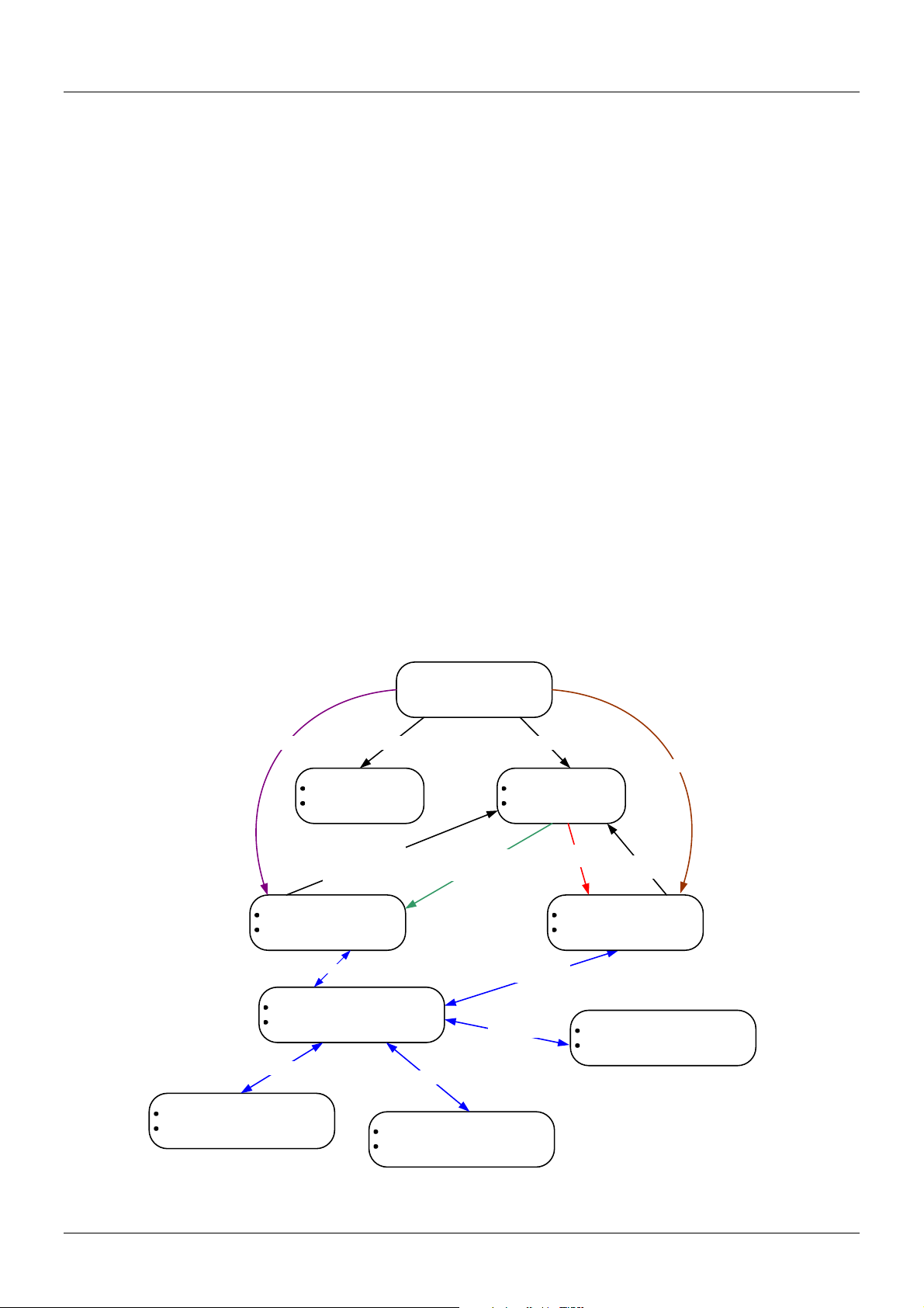
The following state diagram describes the main command modes and how to enter each one:
vi
Page 7

-
Note: Not all configuration modes are listed in the above figure. For example, in
global configuration mode, enter “router ospf” to enter OSPF router configuration
mode
The following table briefly lists the available command modes. Only the basic command modes and some
of the sub-configuration modes are enumerated. The basic command modes and basic sub-configuration
modes are further described in the following chapters. Descriptions for the rest of the sub-configuration
modes are not provided in this section. For more information on the additional sub-configuration modes,
the user should refer to the chapters relating to these functions.
The available command modes and privilege levels are described below:
Command Mode & Privilege Level Purpose
User EXEC mode at Basic User level For checking basic system settings, allowing users to
change the local terminal session settings, and verifying
basic network connectivity. Checking security related
settings is not allowed at this command mode and
privilege level.
User EXEC mode at Advanced User level This level has almost the same access rights as user
EXEC mode at basic user level, except that a user in this
mode and at this level can enter privileged EXEC mode
by entering the enable command.
Privileged EXEC mode at Power User level For changing both local and global terminal settings,
monitoring, and performing certain system
administration tasks. The system administration tasks
that can be performed at this level includes the clearing
of system configuration settings, except for any security
related information, such as user accounts, SNMP
account settings etc.
Privileged EXEC mode at Administrator
level
This level is identical to privileged EXEC mode at power
user level, except that a user at the administrator level
can monitor and clear security related settings.
Global Configuration Mode at Power User
level
For applying global settings, except for security related
settings, on the entire Switch. In addition to applying
global settings on the entire Switch, the user can access
other sub-configuration modes from global configuration
mode.
Global Configuration Mode at Administrator
level
For applying global settings on the entire Switch. In
addition to applying global settings on the entire Switch,
the user can access other sub-configuration modes from
global configuration mode.
Interface Configuration Mode at Power
User level
For applying interface related settings.
vii
Page 8

-
Command Mode & Privilege Level Purpose
VLAN Interface Configuration Mode For applying VLAN interface related settings.
VLAN Configuration Mode For applying settings to a VLAN.
IP Access-List Configuration Mode For specifying filtering criteria for an IP access list.
User EXEC Mode at Basic User Level
This command mode is mainly designed for checking basic system settings, allowing users to change the
local terminal session settings and carry out basic network connectivity verification. One limitation of this
command mode is that it cannot be used to display information related to security. The most significant
limitation of this command mode is that there is no way of changing the access right level of the logged in
user.
This command mode can be entered by logging in as a basic user.
User EXEC Mode at Advanced User Level
User EXEC mode at advanced user level has the same purpose as user EXEC mode at basic user level,
except that user EXEC mode at advanced user level is allowed to use the enable command to enter
privileged EXEC mode.
This command mode can be entered by logging in as an advanced user or by using the disable
command in privileged EXEC mode.
In the following example, the user is currently logged in as an advanced user in privileged EXEC mode
and uses the disable command to return to user EXEC mode at advanced user level:
DGS-6600:15#disable
DGS-6600:2>
Privileged EXEC Mode at Power User Level
Users logged into the Switch in privileged EXEC mode at this level can change both local and global
terminal settings, monitor, and perform system administration tasks like clearing configuration settings
(except for security related information such as user accounts, SNMP account settings etc.)
There are two methods that a user can use to enter privileged EXEC mode at power user level. The first
method is to login to the Switch with a user account that has a privilege level of 12. The other method is to
use the enable privilege LEVEL command in user EXEC mode.
In the following example, the user enters privileged EXEC mode at power user level by logging in with a
user account called “power-user” that has a privilege level of 12:
viii
Page 9

-
User Access Verification
Username: power-user
Password:
DGS-6600 Chassis-based High-Speed Switch
Command Line Interface
Firmware: 4.00.00
Copyright (c) 2012 D-Link Corporation. All rights reserved.
DGS-6600:12#
In the following example, the user enters the enable privilege LEVEL command in user EXEC mode to
enter privileged EXEC mode at Power User level:
DGS-6600:2>enable privilege 12
DGS-6600:12#
Privileged EXEC Mode at Administrator Level
This command mode has a privilege level of 15. Users logged in with this command mode can monitor all
system information and change any system configuration settings mentioned in this Configuration Guide.
There are two methods that a user can use to enter privileged EXEC mode at administrator level. The first
method is to login to the Switch with a user account that has a privilege level of 15. The second method
requires a user to login to the Switch in as a user with an advanced user or power user level and and use
the enable privilege LEVEL command.
In this command mode, the user can return to user EXEC mode at an advanced user level by entering the
disable command.
In the following example, the user is currently logged in as an administrator in privileged EXEC mode and
uses the disable command to return to user EXEC mode at an advanced user level:
DGS-6600:15#disable
DGS-6600:2>
ix
Page 10

-
In the following example, the user enters the enable privilege LEVEL command in privileged EXEC
mode at power user level to enter privileged EXEC mode at an administrator level:
DGS-6600:12#enable privilege 15
DGS-6600:15#
Global Configuration Mode
The primary purpose of global configuration mode is to apply global settings on the entire Switch. Global
configuration mode can be accessed at both power user and administrator level. However, security
related settings are not accessible at power user level. In addition to applying global settings on the entire
Switch, the user can also access other sub-configuration modes.
In order to access global configuration mode, the user must be logged in as an administrator or power
user and use the configure terminal command in privileged EXEC mode.
In the following example, the user is logged in as an Administrator in privileged EXEC mode and uses the
configure terminal command to access global configuration mode:
DGS-6600:15#configure terminal
DGS-6600:15(config)#
The exit command is used to exit global configuration mode and return to privileged EXEC mode.
The procedures to enter the different sub-configuration modes can be found in the related chapters in this
Configuration Guide. The command modes are used to configure the individual functions.
Interface Configuration Mode
Interface configuration mode is used to configure the parameters for an interface or a range of interfaces.
An interface can be a physical port, VLAN, or other virtual interface. Thus, interface configuration mode is
distinguished further according to the type of interface. The command prompt for each type of interface is
slightly different.
VLAN Interface Configuration Mode
VLAN interface configuration mode is one of the available interface modes and is used to configure the
parameters of a VLAN interface.
To access VLAN interface configuration mode, use the following command in global configuration mode:
Command Explanation
DGS-6600:15(config)#interface
Enters VLAN interface configuration mode.
vlanVLAN-ID
x
Page 11

DGS-6604 m
Command Listing by Feature
802.1x dot1x auth-mode — 190
dot1x auth-protocol — 191
dot1x control-direction — 192
dot1x default — 193
dot1x forward-pdu — 194
dot1x guest-vlan (interface configuration) — 195
dot1x initialize — 197
dot1x max-req — 198
dot1x pae — 199
dot1x port-control — 200
dot1x re-authenticate — 201
dot1x re-authentication — 202
dot1x system-auth-control — 203
dot1x timeout — 204
dot1x user — 205
show dot1x — 671
show dot1x user — 675
show dot1x vlan — 676
AAA aaa authentication — 30
aaa authorization — 32
aaa group server — 33
server — 616
show aaa — 646
show aaa group server — 649
CLI Reference Guide
1
Page 12

DGS-6604 m
Access Control Lists
ip access-group — 252
ip access-list — 254
ipv6 access-list — 366
mac access-group — 460
mac access-list — 461
periodic — 543
permit | deny (ip access-list) — 544
permit | deny (ipv6 access list) — 547
permit | deny (mac access-list) — 549
resequence access-list — 601
show access-group — 650
show access-list — 651
Access Management
show time-range — 926
time-range — 1028
banner login — 61
command prompt — 133
configure terminal — 135
disable — 180
enable — 207
enable password — 208
end — 211
exit — 229
help — 242
ip http server — 292
ip http service-port — 293
ip telnet server — 359
ip telnet service-port — 360
CLI Reference Guide
2
Page 13

DGS-6604 m
ip trusted-host — 361
login — 450
logout — 451
password encryption — 536
show enable password — 677
show history — 689
show ip trusted-host — 795
show username — 930
show user-session — 931
telnet — 1015
terminal length — 1020
terminal timeout — 1021
terminal width — 1022
username — 1042
Basic IPv4 arp — 56
arp timeout — 57
clear arp-cache — 99
ip address — 258
show arp — 652
show ip interface — 739
Basic IPv6 clear ipv6 neighbors — 115
default ipv6 nd prefix — 164
ipv6 address — 367
ipv6 enable — 377
ipv6 hop-limit — 378
ipv6 nd managed-config-flag — 379
CLI Reference Guide
3
Page 14

DGS-6604 m
ipv6 nd other-config-flag — 380
ipv6 nd prefix — 381
ipv6 nd ra-interval — 382
ipv6 nd ra-lifetime — 383
ipv6 nd reachable-time — 384
ipv6 nd retrans-timer — 385
ipv6 nd suppress-ra — 386
ipv6 neighbor — 387
show ip dhcp pool — 709
show ipv6 interface brief — 804
show ipv6 neighbors — 805
Basic Switch show environment — 678
show system — 921
show unit — 928
show version — 932
BGP address-family ipv4 — 40
aggregate-address — 41
bgp always-compare-med — 71
bgp asnotation dot — 72
bgp bestpath as-path ignore — 74
bgp bestpath compare-routerid — 76
bgp default ipv4-unicast — 77
bgp default local-preference — 78
bgp deterministic-med — 79
bgp enforce-first-as — 80
bgp log-neighbor-changes — 83
CLI Reference Guide
4
Page 15

DGS-6604 m
bgp router-id — 84
clear ip bgp — 104
clear ip bgp peer-group — 106
default-information originate (BGP) — 167
ip community-list — 266
ip dhcp snooping verify MAC-address — 287
match as-path — 471
match community — 472
neighbor advertisement-interval — 510
neighbor description — 511
neighbor filter-list — 512
neighbor peer-group (create group) — 513
neighbor peer-group (add group member) — 515
neighbor remote-as — 516
neighbor route-map — 517
neighbor send-community — 518
neighbor shutdown — 519
neighbor timers — 520
neighbor update-source — 521
neighbor weight — 522
network (BGP) — 527
redistribute — 590
router bgp — 607
set as-path — 624
set community — 625
set origin — 638
set weight — 639
CLI Reference Guide
5
Page 16

DGS-6604 m
show ip arp inspection — 693
show ip bgp — 697
show ip bgp community-list — 699
show ip bgp filter-list — 701
show ip bgp neighbors — 702
show ip community-list — 705
timers bgp — 1027
Chassis reboot — 589
show system high-availability — 925
system high-availability — 1012
Digital
Diagnostic
Monitoring
(DDM)
ddm bias-current — 151
ddm log — 153
ddm rx-power — 154
ddm shutdown — 156
ddm state — 157
ddm temperature — 158
ddm voltage — 162
ddm tx-power — 160
show ddm — 665
show ddm configuration — 666
show ddm status — 668
DHCP Client
clear ipv6 dhcp client — 114
(IPv6)
ipv6 address — 368
ipv6 dhcp client information refresh minimum — 372
ipv6 dhcp client pd — 373
show ipv6 dhcp — 797
CLI Reference Guide
6
Page 17

DGS-6604 m
show ipv6 general-prefix — 801
DHCP Relay (IPv4)
DHCP Relay (IPv6)
ip dhcp relay — 271
ip dhcp relay address — 272
ip dhcp relay hops — 273
ip dhcp relay information check — 274
ip dhcp relay information option — 275
ip dhcp relay information policy — 277
ip dhcp relay information trust-all — 278
ip dhcp relay information trusted — 279
show ip dhcp relay — 712
show ip dhcp relay information trusted-sources — 713
ipv6 dhcp relay destination — 375
show ipv6 dhcp relay interface — 800
DHCP Server
(IPv4)
accept dhcp client-identifier — 34
accept dhcp relay-agent — 35
based-on client-id — 63
based-on c-vid — 64
based-on interface-ip-address — 65
based-on mac-address — 66
based-on relay-ip-address — 67
based-on s-vid — 68
based-on user-class — 69
based-on vendor-class — 70
bootfile — 91
clear ip dhcp binding — 108
clear ip dhcp conflict — 110
CLI Reference Guide
7
Page 18

DGS-6604 m
clear ip dhcp server statistics — 112
default-router — 175
dns-server — 183
domain-name — 184
ip address-list — 260
ip dhcp ping packets — 268
ip dhcp ping timeout — 269
ip dhcp pool — 270
lease — 424
netbios node-type — 523
netbios scope-id — 524
DHCP Server Screening/ Client Filtering
netbios wins-server — 525
next-server — 529
service dhcp — 618
show ip dhcp binding — 706
show ip dhcp conflict — 708
show ip dhcp pool — 709
show ip dhcp server — 715
show ip dhcp server statistics — 716
subnet-mask — 1003
ip dhcp screening — 280
ip dhcp screening ports — 281
ip dhcp screening suppress-duration — 282
ip dhcp screening trap-log — 283
show ip dhcp screening — 714
DHCP
ip dhcp snooping — 284
Snooping
CLI Reference Guide
8
Page 19

DGS-6604 m
ip dhcp snooping information option — 285
ip dhcp snooping trust — 286
ip dhcp snooping verify MAC-address — 287
ip dhcp snooping vlan — 288
show ip dhcp snooping — 718
show ip dhcp snooping binding — 719
show ip dhcp snooping database — 722
DoS
clear dos_prevention counter — 101
Prevention
dos_prevention action — 185
dos_prevention type — 186
show dos_prevention — 669
DVMRP ip dvmrp — 290
ip dvmrp metric — 291
show ip dvmrp neighbor — 724
show ip dvmrp prune — 727
show ip dvmrp route — 728
Dynamic ARP
ip arp inspection trust — 261
Inspection
ip arp inspection validate — 262
ip arp inspection vlan — 264
ERPS erpi enable — 212
erps — 225
erps domain — 226
erpi protected-vlan — 213
erpi raps-vlan — 215
erpi ring-mel — 216
erpi ring-port — 217
CLI Reference Guide
9
Page 20

DGS-6604 m
erpi rpl — 219
erpi tc-propagation — 220
erpi timer — 221
erpi type — 223
show erps domain — 681
show erps erpi — 683
Errdisable errdisable recovery — 227
show errdisable recovery — 685
File System delete — 176
dir — 179
GVRP clear gvrp statistics interface — 103
graceful-restart — 232
gvrp (Interface) — 236
gvrp advertise (Interface) — 237
gvrp advertise (VLAN) — 238
gvrp dynamic-vlan-creation — 239
gvrp forbidden — 240
gvrp timer — 241
show gvrp configuration — 686
show gvrp statistics — 688
High
bgp graceful-restart — 81
Availability
ip multicast graceful-restart — 314
ipv6 ospf graceful-restart — 390
ipv6 ospf restart helper — 391
ipv6 rip graceful-restart — 398
ospf graceful-restart — 530
CLI Reference Guide
10
Page 21

DGS-6604 m
ospf restart helper — 531
redundancy force-switchover — 599
rip graceful-restart — 603
show redundancy — 899
IGMP ip igmp access-group — 294
ip igmp last-member-query-interval — 296
ip igmp query-interval — 297
ip igmp query-max-response-time — 298
ip igmp robustness-variable — 299
ip igmp version — 308
show ip igmp group — 729
show ip igmp interface — 732
IGMP
ip igmp snooping — 300
Snooping
ip igmp snooping querier — 305
ip igmp snooping static-group — 306
show ip igmp snooping — 733
show ip igmp snooping group — 735
show ip igmp snooping mrouter — 738
Interface clear counters — 100
description — 177
encapsulation dot1q — 209
interface — 248
interface range — 250
show interface — 690
show interface status err-disabled — 692
IP Utility ping — 551
CLI Reference Guide
11
Page 22

DGS-6604 m
traceroute — 1029
IP Multicast ip mroute — 310
ip multicast-routing — 315
show ip mroute — 742
show ip mroute forwarding-cache — 744
IPv6 Protocol Independent
IP Source Guard
ipv6 route — 402
ipv6 unicast-routing long-prefix — 410
ipv6 unicast-routing long-prefix log — 412
show ipv6 protocols — 815
show ipv6 route — 819
show ipv6 route summary — 822
show ipv6 unicast-routing long-prefix status — 823
ip verify source vlan dhcp-snooping — 363
ip source binding — 355
show ip source binding — 792
show ip verify source — 796
IPv6 Tunnel interface tunnel — 251
ipv6 nd suppress-ra — 386
tunnel destination — 1039
tunnel mode — 1040
tunnel source — 1041
Jumbo Frame ip mtu — 312
max-rcv-frame-size — 477
mtu — 504
L2 FDB clear mac address-table — 121
CLI Reference Guide
12
Page 23

DGS-6604 m
mac address-table aging destination-hit — 462
mac address-table aging-time — 463
mac address-table static — 464
multicast filtering-mode — 506
show mac address-table — 849
show mac address-table aging destination-hit — 851
show mac address-table aging-time — 852
show multicast filtering-mode — 882
LACP channel-group — 92
lacp port-priority — 421
LLDP/LLDPMED
lacp system-priority — 422
port-channel load-balance — 572
show channel-group — 655
clear lldp statistics — 119
clear lldp neighbors — 118
lldp dot1-tlv-select — 425
lldp dot3-tlv-select — 428
lldp fast-count — 430
lldp hold-multiplier — 431
lldp management-address — 432
lldp med-tlv-select — 434
lldp receive — 436
lldp reinit — 437
lldp run — 438
lldp tlv-select — 439
lldp transmit — 441
CLI Reference Guide
13
Page 24

DGS-6604 m
lldp tx-delay — 442
lldp tx-interval — 443
show lldp — 824
show lldp interface — 826
show lldp local interface — 828
show lldp management-address — 833
show lldp neighbor interface — 835
show lldp statistics — 841
show lldp statistics interface — 842
Loopback Detection
Loopback Interface
Management Port
loopback-detection (global) — 453
loopback-detection (interface) — 454
loopback-detection mode — 456
loopback-detection interval-time — 457
show loopback-detection — 846
description (loopback interface) — 178
interface loopback — 249
ip address (loopback interface) — 256
shutdown (loopback interface) — 953
default-gateway (management port) — 165
ip address (management port) — 257
ip mtu (management port) — 313
ipv6 address (management port) — 370
ipv6 default-gateway (management port) — 371
mgmt-if — 480
show mgmt-if — 857
shutdown (Management Port) — 954
CLI Reference Guide
14
Page 25

DGS-6604 m
Mirror monitor session — 481
monitor session destination remote vlan — 483
monitor session source remote vlan — 487
remote-span — 600
show monitor session — 858
MPLS backoff maximum — 60
class-map (mpls) — 98
graceful-restart — 232
graceful-restart neighbor-liveness timer — 233
graceful-restart recovery timer — 234
keepalive_holdtime — 413
label-retention-mode — 420
ldp router-id — 423
loop-detection — 452
lsp trigger — 458
lsp-control-mode — 459
lsp trigger — 458
match (mpls) — 470
max-hop-count — 475
md5 authentication — 478
mpls ip (global configuration) — 488
mpls ip (interface configuration) — 489
mpls label protocol ldp (global configuration) — 490
mpls label protocol ldp (interface configuration) — 491
mpls ldp hello-holdtime — 492
mpls ldp hello-interval — 493
mpls ldp max-path-vector — 494
CLI Reference Guide
15
Page 26

DGS-6604 m
mpls ldp targeted-hello-accept — 495
mpls ldp targeted-peer — 496
mpls qos policy — 497
mpls static ftn — 498
mpls static ilm — 500
neighbor password — 514
ping lsp — 553
show lsp trigger — 848
show mpls — 860
show mpls forwarding-table — 861
show mpls interface — 866
show mpls ldp bindings — 868
show mpls ldp discovery — 869
show mpls ldp interface — 870
show mpls ldp neighbor — 872
show mpls ldp neighbor password — 873
show mpls ldp parameter — 874
show mpls ldp session — 876
show mpls ldp statistic — 878
show mpls ldp targeted-peer — 879
show mpls qos — 880
targeted-hello — 1014
traceroute lsp — 1032
transport-address — 1036
trust-exp — 1038
MSTP instance — 246
name — 507
CLI Reference Guide
16
Page 27

DGS-6604 m
revision — 602
show spanning-tree mst — 913
spanning-tree mst (cost | port-priority) — 982
spanning-tree mst (forward-time | max-age | max-hops) — 983
spanning-tree mst configuration — 984
spanning-tree mst hello-time — 985
spanning-tree mst priority — 986
Network Load
arp — 56
Balancing
mac address-table static — 464
OSPFv2 area default-cost — 42
area nssa — 44
area range — 46
area stub — 48
area virtual-link — 50
auto-cost reference-bandwidth — 58
clear ip ospf — 113
default-information originate (OSPF) — 166
default-metric (OSPF) — 171
host area — 243
ip ospf authentication — 316
ip ospf authentication-key — 317
ip ospf cost — 318
ip ospf dead-interval — 319
ip ospf hello-interval — 320
ip ospf message-digest-key — 321
ip ospf priority — 323
CLI Reference Guide
17
Page 28

DGS-6604 m
ip ospf retransmit-interval — 324
ip ospf shutdown — 325
ip ospf transmit-delay — 326
ip ospf mtu-ignore — 322
network area — 528
passive-interface — 532
redistribute (OSPF) — 591
router ospf — 610
router-id — 612
show ip ospf — 746
show ip ospf border-routers — 748
show ip ospf database — 749
show ip ospf database asbr-summary — 751
show ip ospf database external — 753
show ip ospf database network — 754
show ip ospf database nssa-external — 756
show ip ospf database router — 758
show ip ospf database summary — 761
show ip ospf host-route — 763
show ip ospf interface — 764
show ip ospf neighbor — 766
show ip ospf virtual-links — 767
OSPFv3 area default-cost (IPv6) — 43
area range (IPv6) — 47
area stub (IPv6) — 49
area virtual-link (IPv6) — 54
auto-cost reference-bandwidth (IPv6) — 59
CLI Reference Guide
18
Page 29

DGS-6604 m
clear ipv6 ospf process — 116
default-information originate (IPv6 OSPF) — 168
default-metric (IPv6 OSPF) — 172
ipv6 ospf cost — 388
ipv6 ospf dead-interval — 389
ipv6 ospf graceful-restart — 390
ipv6 ospf mtu-ignore — 393
ipv6 ospf retransmit-interval — 395
ipv6 ospf shutdown — 396
ipv6 ospf transmit delay — 397
ipv6 route — 402
ipv6 router ospf area — 408
passive-interface (IPv6 OSPF) — 533
redistribute (IPv6 OSPF) — 593
router-id (IPv6) — 613
router ipv6 ospf — 608
router ospf — 610
show ipv6 ospf — 807
show ipv6 ospf border-routers — 809
show ipv6 ospf database — 810
show ipv6 ospf interface — 811
show ipv6 ospf neighbor — 812
show ipv6 ospf route — 813
show ipv6 ospf virtual-links — 814
show ipv6 protocols — 815
Password
password recovery — 538
Recovery
CLI Reference Guide
19
Page 30

Preface
PIM ip pim — 327
ip pim accept-register — 328
ip pim bsr-candidate — 329
ip pim dr-priority — 331
ip pim join-prune-interval — 332
ip pim prune-limit-interval — 333
ip pim query-interval — 334
ip pim register-checksum-include-data — 335
ip pim register-suppresion — 336
ip pim rp-address — 337
ip pim rp-candidate — 338
ip pim state-refresh origination-interval — 340
show ip pim — 769
show ip pim bsr — 770
show ip pim interface — 771
show ip pim mroute — 773
show ip pim neighbor — 775
show ip pim rp mapping — 777
show ip pim rp-hash — 778
POE poe port priority — 556
poe port description — 555
poe service-policy — 559
police — 560
show poe power system — 884
show poe power-inline — 886
Policy-based
ip policy route-map — 341
Route
show ip policy — 779
CLI Reference Guide - Preliminary Draft
20
Page 31

Preface
Port Security clear port-security — 124
show port-security — 890
switchport port-security — 1007
Power Saving power-saving — 573
show power-saving — 892
Protocol
distance — 181
Independent
ip route — 350
ip route multi-path — 354
ip route ecmp load-balance — 352
maximum-paths — 476
show ip protocols — 780
show ip route — 786
show ip route summary — 791
show ip route ecmp load-balance — 790
Proxy ARP ip local-proxy-arp — 309
ip proxy-arp — 343
show ip proxy-arp — 783
QoS class — 94
class-map — 96
color-aware — 132
match — 466
police — 560
police aggregate — 565
police cir — 566
policy-map — 570
qos aggregate-policer — 575
qos bandwidth — 578
CLI Reference Guide - Preliminary Draft
21
Page 32

DGS-6604 m
qos cos — 579
qos deficit-round-robin — 580
qos dscp-mutation — 583
qos map cos-color — 584
qos map dscp-color — 585
qos map dscp-cos — 586
qos map dscp-mutation — 587
qos trust — 588
service-policy — 619
set — 622
show class-map — 659
QinQ (VLAN Tunnel)
show policy-map — 888
show qos aggregate-policer — 893
show qos interface — 894
show qos map — 898
clear vlan-tunnel ctag-mapping dynamic — 127
cos remarking — 142
show vlan-tunnel — 940
show vlan-tunnel ctag-mapping — 943
vlan encapsulation — 1046
vlan remarking — 1048
vlan-tunnel — 1050
vlan-tunnel ctag-mapping dynamic — 1051
vlan-tunnel ctag-mapping static — 1052
vlan-tunnel ingress checking — 1053
vlan-tunnel interface-type — 1054
vlan-tunnel remove-inner-tag — 1055
CLI Reference Guide
22
Page 33

DGS-6604 m
vlan-tunnel tpid — 1056
RIP accept-lifetime — 37
default-information originate (RIP) — 170
default-metric (RIP) — 173
ip rip authentication key-chain — 344
ip rip authentication mode — 346
ip rip receive version — 347
ip rip send version — 348
ip rip v2-broadcast — 349
key — 414
key chain — 416
key-string — 418
neighbor — 508
network — 526
passive interface (RIP) — 534
redistribute (RIP) — 595
router rip — 611
send-lifetime — 614
show ip key-chain — 741
show ip rip database — 784
show ip rip interface — 785
timers — 1024
version — 1044
RIPng clear ipv6 rip — 117
default-information originate (RIP IPv6) — 169
default-metric (OSPF) — 171
CLI Reference Guide
23
Page 34

DGS-6604 m
default-metric (RIP IPv6) — 174
ipv6 rip graceful-restart — 398
ipv6 rip split-horizon — 400
ipv6 rip split-horizon poisoned — 401
ipv6 router rip — 409
neighbor (RIP IPv6) — 509
passive-interface (RIP IPv6) — 535
redistribute (RIP IPv6) — 597
router ipv6 rip — 609
show ipv6 protocols — 815
show ipv6 rip database — 817
show ipv6 rip interface — 818
timers basic — 1025
RMON rmon statistics — 604
Route Map match ip address — 473
match ipv6 address — 474
route-map — 605
set default interface — 627
set ip precedence — 633
set interface — 628
set ipv6 default next-hop — 634
set ipv6 next-hop — 636
set origin — 638
set ip next-hop — 631
show route-map — 900
Safeguard clear cpu-protect counters — 102
CLI Reference Guide
24
Page 35

DGS-6604 m
cpu-protect type — 147
cpu-protect safeguard — 144
cpu-protect sub-interface — 146
show cpu-protect safeguard — 661
show cpu-protect sub-interface — 662
show ddm — 665
sFlow sflow — 640
sflow poller — 641
sflow receiver — 642
sflow sampler — 644
show sflow — 902
SNMP
show snmp-server — 909
Management
snmp-server — 956
snmp-server contact — 959
snmp-server enable traps — 960
snmp-server enable traps snmp — 961
snmp-server location — 968
system-name — 1013
SNMP v3 show snmp — 904
show snmp user — 907
snmp-server community — 957
snmp-server engineID local — 963
snmp-server group — 964
snmp-server host — 966
snmp-server user — 969
snmp-server view — 971
CLI Reference Guide
25
Page 36

DGS-6604 m
SSH crypto key — 150
ip ssh — 357
show ip ssh — 794
show ssh — 916
ssh — 993
Storm Control show storm-control — 918
storm-control (Interface) — 995
storm-control action (Interface) — 996
storm-control level (Interface) — 998
storm-control timer (Global) — 1000
STP clear spanning-tree detected-protocols — 126
show spanning-tree — 911
spanning-tree enable (Global configuration) — 974
spanning-tree state (Interface configuration) — 975
spanning-tree (timers) — 976
spanning-tree cost — 977
spanning-tree fast-forwarding — 978
spanning-tree guard root — 979
spanning-tree link-type — 980
spanning-tree mode — 981
spanning-tree port-priority — 987
spanning-tree priority — 988
spanning-tree tcnfilter — 989
spanning-tree transmit hold-count — 990
Super VLAN supervlan — 1004
subvlan — 1005
CLI Reference Guide
26
Page 37

DGS-6604 m
subvlan-address-range — 1006
show supervlan — 920
Switch Port duplex — 206
flowcontrol — 230
media-type — 479
shutdown (interface) — 952
speed — 991
Syslog clear logging — 120
logging file — 444
logging host — 445
logging level — 447
logging on — 449
show logging — 843
System File
boot config — 85
Management
bootfile — 91
clear running-config — 125
copy — 136
show boot — 654
show running-config — 901
show startup-config — 917
Time and SNTP clock set — 128
clock summer-time — 129
clock timezone — 131
show clock — 660
show sntp — 910
sntp server — 973
CLI Reference Guide
27
Page 38

DGS-6604 m
Traffic
show traffic-segmentation — 927
Segmentation
traffic-segmentation forward — 1034
VLAN acceptable-frame — 36
access vlan — 39
dot1v binding protocol-group — 188
dot1v protocol-group — 189
hybrid vlan VLAN-ID — 244
ingress-checking — 245
mac-base (vlan) — 465
pvid VLAN-ID — 574
show dot1v — 670
show vlan — 933
subnet-base (vlan) — 1002
trunk allowed-vlan — 1037
vlan — 1045
vlan name — 1047
VPLS clear mac address-table vpls — 122
encapsulation (VPLS) — 210
mtu (VPLS) — 505
peer — 537
peer backup — 542
show mac address-table vpls — 853
show vpls — 944
vpls — 1061
vpls-id — 1062
xconnect vpls — 1075
CLI Reference Guide
28
Page 39

DGS-6604 m
VRRP show vrrp — 948
show vrrp brief — 951
vrrp critical-ip — 1063
vrrp ip — 1065
vrrp preempt — 1066
vrrp priority — 1068
vrrp shutdown — 1070
vrrp timers advertise — 1071
VPWS mpls static ilm (VPWS) — 502
mpls static l2vc-ftn — 503
show mpls forwarding-table (VPWS) — 864
show multicast filtering-mode — 882
xconnect — 1072
xconnect vpls — 1075
Voice Vlan show vlan voice-vlan — 937
switchport voice-vlan state — 1010
voice-vlan — 1057
voice-vlan cos — 1058
voice-vlan oui — 1059
CLI Reference Guide
29
Page 40

DGS-6600 Series Switch m aaa authentication
A
aaa authentication
Use this command to enable the AAA authentication function (console, telnet,
ssh or http) for authentication of user interface applications. Use the no
command to disable the authentication function.
Note: Use aaa group server to first define authentication servers before aaa
authentication can be configured.
aaa authentication [login | enable] [console | telnet | http | ssh] METHOD1 [METHOD2...]
no aaa authentication [login | enable] [console | telnet | http | ssh] METHOD1 [METHOD2...]
Syntax Description
login
(Optional) Enable authentication for normal login mode. Enter the console,
telnet, or http keyword. If neither login nor enable are specified, both login and
enable are implied.
enable
(Optional) Enable authentication for normal enable mode. Enter the console,
telnet, or http keyword. If neither login nor enable are specified, both login and
enable are implied.
console
(Optional) Specifies that the type of application used for system access
authentication is console.
telnet
(Optional) Specifies that the type of application used for system access
authentication is telnet.
http
(Optional) Specifies that the type of application used for system access
authentication is http.
ssh (Optional) Specifies that the type of application used for system access
authentication is SSH.
METHOD1
[METHOD2...]
Identifies the list of methods that the authentication algorithm tries in the given
sequence. At least one method must be entered; up to two methods can be
identified by keyword. The keywords for AAA authentication login and enable
configuration methods are described as follows:
• local Uses the local username database for authentication.
• group GROUP-NAME Uses a subset of authentication servers for
authentication as defined by the aaa group server command.
Default No aaa authentication is specified for console, telnet, http and ssh applications.
Command Mode Global configuration.
Usage Guideline Use aaa authentication to configure login, or to enable a listing for a specified
application or all applications (such as console, telnet, http and ssh etc.) should
no application option be specified.
You can specify multiple methods for the login and enable authentications per
application. The new setting will overwrite the old association.
CLI Reference Guide
30
Page 41

DGS-6600 Series Switch m aaa authentication
Use the no aaa authentication to disable the login or the enable list for the
specified application or all applications (such as console, telnet, http and ssh
etc.) if no application option is specified. This command should be executed
when the specified application is configured by any group, otherwise it would be
useless, because the aaa authentication default configuration is local.
To configure AAA authentication, you must first define a group of authentication
servers (by aaa group server command). If a non-existed group server is
referred, an error is displayed for that. The group server defines the types of
authentication to be performed and the sequence in which they will be
performed.
A method list is a sequential list describing the authentication methods to be
queried in order to authenticate a user. Method lists enable you to designate one
or more security protocols to be used for authentication, thus ensuring a backup
system for authentication in case the initial method fails. Switch system uses the
first listed method to authenticate users. If that method fails to respond, the
switch system selects the next authentication method listed in the method list.
This process continues until there is successful communication with a listed
authentication method, or all methods defined in the method list are exhausted.
It is important to note that the switch system attempts authentication with the next
listed authentication method only when there is no response from the previous
method. If authentication fails at any point in this cycle-meaning that the security
server or local usernames database responds by denying the user access-the
authentication process stops and no other authentication methods are
attempted.
Local authentication uses locally configured login and enable passwords to
authenticate login attempts. The login and enable passwords are local to each
switch and are not mapped to the individual usernames. By default, local
authentication is used. Once you specify the authentication method list for the
login/enable on some application, the switch won't attempt local authentication
even the specified authentication methods fail.
If the method list is empty, then local authentication will be used.
In order to make AAA authentication take effect, you have to create at least one
local user account for login and set up the enable password.
Example The following example sets a login method list for an authenticate login attempt
from all of the applications (including console, telnet, ssh, http). The methods
start from group2.
Switch(config)# aaa authentication login group group2 local
Switch(config)#
Verify the settings by entering the show aaa command.
CLI Reference Guide
31
Page 42

DGS-6600 Series Switch m aaa authorization
aaa authorization
Use this command to enable the authorization function. Use the no form of the
command to disable AAA authorization.
aaa authorization
no aaa authorization
Syntax None.
Default Disabled.
Command Mode Global configuration at privilege level 15.
Usage Guideline When the AAA authorization function is enabled, the system will use
configuration settings authorized by the RADIUS server in addition to the
RADIUS server authentication function. Settings can include VLAN assignment,
user priority assignment and bandwidth assignment.
If AAA authorization is disabled, the system only accepts the authentication
function from the RADIUS server and ignore any additional configuration settings
supplied by the RADIUS server.
Example This example shows how to enable the authorization:
Switch# configure terminal
Switch(config)# aaa authorization
Verify the settings by entering the show system protocol-state command.
CLI Reference Guide
32
Page 43

DGS-6600 Series Switch m aaa group server
aaa group server
Use the aaa group server command to enter AAA group server mode and identify
AAA server groups used for AAA authentication. In AAA group server mode
server hosts are grouped into distinct lists and distinct methods.
To remove a group server from the configuration list, use the no aaa group server
form of this command.
aaa group server GROUP-NAME
no aaa group server GROUP-NAME
Syntax Description
GROUP-NAME Character string used to name the group of servers used for group server
method AAA authentication. The group name can be up to 32 characters in
length.
Default There is no aaa group server.
Command Mode Global configuration at privilege level 15.
Usage Guideline The AAA group server method is defined for AAA authentication for user login or
configuration. The aaa authentication command is used to define the group
server method and specify the AAA server group.
Use aaa group server command to enter AAA group server mode. If the group
name specified does not exist, the switch creates the new group. Once in AAA
group server mode, use the server command to define and configure servers
added to the group.
Example The following example shows the network access server configured to recognize
several RADIUS host entries. The second host entry configured acts as fail-over
backup to the first one. (The RADIUS host entries are tried in the order in which
they are configured).
Switch(config)#aaa group server group1
Switch(config-aaa-groug-server)# server radius 172.19.10.100 key 12345678
Switch(config-aaa-group-server)# server radius 172.19.10.101 key 12345678
Switch(config-aaa-group-server)# end
Switch#
Verify the settings by entering the show aaa group server command.
CLI Reference Guide
33
Page 44

DGS-6600 Series Switch m accept dhcp client-identifier
accept dhcp client-identifier
Use this command to turn on validation checking of the Client Identifier. Use the
no form of the command to turn off validation checking of the Client Identifier.
accept dhcp client-identifier
no accept dhcp client-identifier
Syntax None.
Default client identifier: not evaluated.
Command Mode DHCP pool configuration.
Usage Guideline To validate the DHCP Client Identifier value sent by the client. If a DHCP client
sends a DHCP Client Identifier option, the DHCP server validates the value to
ensure it matches the hardware type and client hardware address. If the values
match, the DHCP server provides service to the client. If the values do not
match, the DHCP server does not respond to the client's request.
If the command is used to set the validation to not check the DHCP Client
Identifier value sent by the client, then the DHCP server only checks the
matching of the client's hardware type and hardware address as a host ID.
Example The following example sets the DHCP pool1 to check the validation of the client
identifier option as DHCP pool1 offers IP addresses.
switch > enable
switch# configure terminal
switch(config)# ip dhcp pool pool1
switch(config-dhcp)# accept dhcp client-identifier
switch(config-dhcp)#
CLI Reference Guide
34
Page 45

DGS-6600 Series Switch m accept dhcp relay-agent
accept dhcp relay-agent
To accept relay agent information use the accept dhcp relay-agent command,
use the no form of the command to reject DHCP relay agent information.
accept dhcp relay-agent [circuit-id|remote-id]
no accept dhcp relay-agent [circuit-id|remote-id]
Syntax Description
circuit-id (Optional) Agent Circuit ID Sub-option.
remote-id (Optional) Agent Remote ID Sub-option
Default DHCP relay-agent is not accepted.
Command Mode DHCP pool configuration.
Usage Guideline If either of circuit-id and remote-id is not specified, it implies that both the circuit-
id and remote-id options are applied with the command. If only the circuit-id or
remote-id is specified, it implies that it only accepts DHCP packets containing
either only a circuit-id or a remote-id.
Examples The following example sets DHCP pool1 to accept circuit id and remote id relay
agent information.
switch > enable
switch# configure terminal
switch(config)# ip dhcp pool pool1
switch(config-dhcp)# accept dhcp relay-agent
switch(config-dhcp)#
The following example sets DHCP pool1 to not accept remote id relay agent
information.
switch > enable
switch# configure terminal
switch(config)# ip dhcp pool pool1
switch(config-dhcp)# no accept dhcp relay-agent remote-id
switch(config-dhcp)#
CLI Reference Guide
35
Page 46

DGS-6600 Series Switch m acceptable-frame
acceptable-frame
Use the acceptable-frame interface command to set the acceptable frame type
of a port for
acceptable-frame {tagged-only | untagged-only | admit-all}
Syntax Description
tagged-only Set acceptable frame type for tagged only of the interface.
untagged-only Set acceptable frame type for untagged only of the interface.
admin-all Set acceptable frame type for all packets of the interface.
Default admit-all
Command Mode interface configuration mode.
Usage Guideline The valid interfaces for this command are physical ports.
IEEE 802.1Q VLANs. The default acceptable frame type is admit-all.
The acceptable-frame interface command can be used to set the acceptable
frame types for physical port interfaces. If an acceptable frame type is tagged-
only, only tagged packets of incoming packets will be received by the interface
and untagged packets will be dropped. If untagged-only, only untagged packets
will be received and tagged packets will be dropped. If admit-all, all packets will
be received.
Example This example shows how to set the acceptable frame type to tagged-only of
eth1.1.
Switch(config)# interface eth1.1
Switch(config-if)# acceptable-frame tagged-only
Verify the settings by entering the show vlan interface command.
CLI Reference Guide
36
Page 47

DGS-6600 Series Switch m accept-lifetime
accept-lifetime
The accept-lifetime command is used to set a time period when an authentication
key on a key chain is accepted as the valid key.
accept-lifetime START-TIME {infinite | END-TIME | duration SECONDS}
Syntax Description
START-TIME The beginning time that the key specified, by the key command, is valid to be
received. The syntax can be either of the following:
HH:MM:SS MONTH DATE YEAR
HH:MM:SS DATE MONTH YEAR
HH-hours
MM-minutes
SS-seconds
MONTH-first three letters of the month
DATE-date (1-31)
YEAR-year (four digits)
The default start time and the earliest acceptable date is January 1, 1993.
infinite Key is valid to be received from the start-time value on.
END-TIME Key is valid to be received from the start-time value until the end-time value.The
syntax is the same as that for the START-TIME. The end-time value must be
after the start-time value. The default end time is an infinite time period.
duration SECONDS Length of time (in seconds) that the key is valid to be received. The range is from
1 to 2147483647 (signed long).
Default Infinite.
Command Mode Key-chain key configuration.
Usage Guideline Only Routing Information Protocol (RIP) Version 2 uses key chains.
Specify a start time value and one of the following values: infinite, end-time, or
duration seconds.
CLI Reference Guide
37
Page 48

DGS-6600 Series Switch m accept-lifetime
Example The following example configures a key chain named chain1. Key 1 named
"forkey1string" will be accepted from 1:30 p.m. to 3:30 p.m. and be sent from
2:00 p.m. to 3:00 p.m. Key 3 named "forkey3string" will be accepted from 2:30
p.m. to 4:30 p.m. and be sent from 3:00 p.m. to 4:00 p.m.
Switch(config)# interface vlan1
Switch(config-if)# ip rip authentication key-chain chain1
Switch(config-if)# ip rip authentication mode text
Switch(config-if)# exit
Switch(config)# router rip
Switch(config-router)# network 172.19.0.0/8
Switch(config-router)# version 2
Switch(config-router)# exit
Switch(config)# key chain chain1
Switch(config-keychain)# key 1
Switch(config-keychain-key)# key-string forkey1string
Switch(config-keychain-key)# accept-lifetime 13:30:00 Jan 25 2009 duration 7200
Switch(config-keychain-key)# send-lifetime 14:00:00 Jan 25 2009 duration 3600
Switch(config-keychain-key)# exit
Switch(config-keychain)# key 3
Switch(config-keychain-key)# key-string forkey3string
Switch(config-keychain-key)# accept-lifetime 14:30:00 Jan 25 2009 duration 7200
Switch(config-keychain-key)# send-lifetime 15:00:00 Jan 25 2009 duration 3600
Switch(config-keychain-key)# exit
Switch(config-keychain)# exit
Verify the settings by entering the show ip key-chain command.
CLI Reference Guide
38
Page 49

DGS-6600 Series Switch m access vlan
access vlan
Use the access vlan interface configuration command to specify the access
VLAN for the interface. Use default interface command to reset to default setting.
access vlan VLAN-ID
default access vlan
Syntax Description
access vlan VLAN-ID Specifies the VLAN for the interface.
Default VLAN 1.
Command Mode Interface configuration mode.
Usage Guideline Physical ports or port-channels are the only valid interfaces for this command.
If a VLAN does not exist, the VLAN will be automatically created and prompt a
message displayed. By default the port has access VLAN 1.
An interface can be specified with only one access VLAN; the succeeding
command overwrites the previous command.
When this command is applied, the port will change to Access mode; the setting
for other modes will disappear and the port's PVID will be changed to the
specified VLAN.
As an access port the port will classify the untagged packet with the access
VLAN which are classified by the protocol-based VLAN, MAC-based VLAN etc.
Examples This example shows how to set an interface port 1.1 to an untagged member of
VLAN 1000.
Switch(config)# interface eth1.1
Switch(config-if)# access vlan 1000
Verify the settings by entering the show vlan interface command.
CLI Reference Guide
39
Page 50

DGS-6600 Series Switch m address-family ipv4
address-family ipv4
Use this command to enter address family configuration mode to configure a
routing session using standard IP Version 4 address prefixes. Use the no form of
this command to remove the IPv4 address family configuration from the running
configuration.
address-family ipv4 [unicast]
no address-family ipv4 [unicast]
Syntax Description
unicast (Optional) Specifies IP Version 4 unicast address prefixes.
Default Unicast prefix support is enabled by default when this command is entered
without any optional keywords.
Command Mode Router configuration.
Usage Guideline Routing information for address family IPv4 unicast is advertised by default for
each BGP routing session configured with the neighbor remote-as command
unless the no bgp default ipv4-unicast command is used before configuring the
neighbor remote-as command.
For all settings configured for IPv4 unicast, the settings also appear in BGP
router configuration mode. That is, for address-family associated settings, the
settings defined in IPv4 unicast address family mode is equivalent to the settings
defined in the router configuration mode.
To l e av e address family configuration mode and return to router configuration
mode without removing the existing configuration, enter the exit command.
Example This example shows how to enter address family configuration mode for the IP
Version 4 address family:
Switch(config)# router bgp 65100
Switch(config-router)# address-family ipv4
Switch(config-router-af)# exit
Switch(config-router)#
CLI Reference Guide
40
Page 51

DGS-6600 Series Switch m aggregate-address
aggregate-address
Use this command to configure BGP aggregate entries. Use the no form of the
command to disable this function.
aggregate-address NETWORK-NUMBER/SUBNET-LENGTH [summary-only] [as-set]
no aggregate-address NETWORK-NUMBER/SUBNET-LENGTH [summary-only] [as-set]
Syntax Description
NETWORK-NUMBER/
SUBNET-LENGTH
summary-only (Optional) Filters all more-specific routes from updates.
as-set (Optional) Generates autonomous system set path information.
Specifies the number of network and the length of network that BGP will
aggregate.
The format of NETWORK-NUMBER/SUBNET-LENGTH can be 10.9.18.2/8.
Default Disabled.
Command Mode Router configuration.
Usage Guideline Aggregates are used to minimize the size of routing tables. Aggregation
combines the characteristics of several different routes and advertises a single
route. The aggregate-address command creates an aggregate entry in the BGP
routing table if any more-specific BGP routes are available in the specified range.
Using the summary-only parameter advertises the prefix only, suppressing the
more-specific routes to all neighbors.
The as-set parameter creates an aggregate entry advertising the path for this
route, consisting of all elements contained in all paths being summarized. Use
the as-set parameter to reduce the size of the path information by listing the AS
number only once, even if it was included in multiple paths that were aggregated.
The as-set parameter is useful when aggregation of information results in
incomplete path information.
Example This example shows how to propagate network 172.0.0.0 and suppresses the
more specific route 172.10.0.0:
Switch(config)# router bgp 65534
Switch(config-router)# aggregate-address 172.0.0.0/8 summary-only
CLI Reference Guide
41
Page 52

DGS-6600 Series Switch m area default-cost
area default-cost
The cost of the default summary route sent into a not-so-stubby area (NSSA) or
a stub area is defined with the area default-cost command in router
configuration mode. The no area default-cost command is used to remove an
assigned default route cost.
area AREA-ID default-cost COST
no area AREA-ID default-cost
Syntax Description
AREA-ID Identifier for the NSSA or stub area. The identifier is specified as either a decimal
value or as an IPv4 prefix. COST is not Optional.
COST COST for the default summary route used for a stub or NSSA. The acceptable
value is a 24-bit number (0~16777215).
Default COST: 1.
Command Mode Router configuration.
Usage Guideline Use this command only on an Area Border Router (ABR) attached to a stub area
or NSSA.
The two stub area router configuration commands are area stub and area
default-cost are configured as follows: for all routers and access servers
attached to the stub area, the area should be configured as a stub area using the
area stub option; the area default-cost command is used only on an ABR
attached to the stub area. The default-cost provides the metric for the summary
default route generated by the ABR into the stub area.
Example The following example assigns a default cost of 20 to stub network 10.0.0.0
Switch# configure terminal
Switch (config)# router ospf
Switch (config-router)# area 10.0.0.0 default-cost 20
Verify the settings by entering the show ip ospf interface command.
CLI Reference Guide
42
Page 53

DGS-6600 Series Switch m area default-cost (IPv6)
area default-cost (IPv6)
To set the summary-default cost of a stub area, use the area default-cost
command. To disable this function, use the no form of this command.
area AREA-ID default-cost COST
no area AREA-ID default-cost
Syntax Description
AREA-ID Identifier of the area about which routes are to be summarized. It can be
specified as either a decimal value or as an IPv4 prefix.
COST (Optional) Metric or cost for this summary route, which is used during the OSPF
SPF calculation to determine the shortest paths to the destination. The value can
be 0 to 16777215.
Default Disabled.
Command Mode Router configuration.
Usage Guideline This command is used only on an Area Border Router (ABR) attached to a stub
area. In all routers and access servers attached to the stub area, the area should
be configured as a stub area using the stub option of the area command. Use the
area default-cost command only on an ABR attached to the stub area. The
default-cost option provides the metric for the summary default route generated
by the ABR into the stub area.
Examples The following example assigns a default cost of 10 to stub area 1.
Switch > enable
Switch # configure terminal
Switch (config) # router ipv6 ospf
Switch (config-router) # area 1 stub
Switch (config-router) # area 1 default-cost 10
CLI Reference Guide
43
Page 54

DGS-6600 Series Switch m area nssa
area nssa
Use this command to define an area as an NSSA (not-so-stubby) area. Use the
no nssa command to remove the NSSA designation.
Note: For OSPFv3 this command is not supported.
area AREA-ID nssa [no-redistribution] [default-information-originate [metric METRIC-VALUE]
[metric-type TYPE-VALUE] ] [no-summary]
no area AREA-ID nssa [no-redistribution] [default-information-originate] [no-summary]
Syntax Description
AREA-ID Specifies the identifier of the area distinguished as the NSSA. The identifier can
be specified as either a decimal value or an IP address.
no-redistribution (Optional) Type 7 external routes will not be re-distributed to the NSSA. When
the user specifies to redistribute routes to the OSPF process, external routes will
always be redistributed to the normal area. This function only takes effect when
the router is an autonomous system boundary router (ASBR).
default-informationoriginate
metric METRIC-
VALUE
metric-type TYPE-
VALUE
no-summary (Optional) This function only take effect when the router is an ABR. Summary
(Optional) For ASBR, a Type 7 default route will be generated into the NSSA
area when it exists in the redistributed routes. For ABR, when this option is
specified, the type-7 default route will always be generated into the NSSA area.
(Optional) Specifies the metric for the default route. If not specified, the value will
be 1. The range for METRIC-VALUE is 0-16777214.
(Optional) For OSPF, the external link type associated with the default route
advertised into the OSPF routing domain. It can be one of two values: Type 1
external route or Type 2 external route. If a metric-type is not specified, the
switch adopts a Type 2 external route.
routes are not advertised into the NSSA.
Default • No NSSA area is configured.
• External routes will be redistributed to the NSSA area in type 7 unless
no-redistribute is specified.
• Type 7 default route will only be advertised by default when default-
information-originate is specified.
• If no-summary is specified, the summary route will not be advertised to
the NSSA area.
Command Mode Router configuration.
Usage Guideline There are no external routes in an OSPF stub area, so it is not possible to
redistribute from another protocol into a stub area.
CLI Reference Guide
44
Page 55

DGS-6600 Series Switch m area nssa
An NSSA allows external routes to be advertised to the area in type 7 link state
advertisement (LSA). These routes are then leaked into other areas. Although,
the external routes from other areas still do not enter the NSSA.
Use the area nssa command to simplify the administration of connecting a
central site using OSPF to a remote site that is using a different routing protocol.
Use this command to extend OSPF to cover the remote connection by defining
the area between the central router and the remote router as an NSSA.
For ASBR NSSA re-distribution, external routes will only be redistributed to the
NSSA when redistribution is configured for the associated OSPF process.
The external routes from other areas within the same AS will not be injected to
the NSSA.
For an ASBR, a Type 7 default route will be generated into the NSSA when it
exists in the redistributed routes.
For an ABR, when this option is specified, the type-7 default route will always be
generated into the NSSA.
If there are multiple default routes generated into the NSSA, the following priority
will be followed: Type 3 priority > Type 7 priority.
Example This command show how to set the nssa area:
Switch# configure terminal
Switch(config)# router ospf
Switch(config-router)# area 1 nssa
Verify the settings by entering the show ip ospf command.
CLI Reference Guide
45
Page 56

DGS-6600 Series Switch m area range
area range
Use this command to summarize and consolidate routes at an area boundary.
Use the no area range command to disable this function.
area AREA-ID range PREFIX/PREFIX-LENGTH [advertise | not-advertise] [cost COST]
no area AREA-ID range [PREFIX/PREFIX-LENGTH]
Syntax Description
AREA-ID Specifies the identifier of the area for which routes are summarized. The
identifier can be specified as either an IP address or a decimal value.
PREFIX/PREFIXLENGTH
advertise (Optional) Sets the status to advertise and generate a Type 3 summary link-state
not-advertise (Optional) Sets the status to DoNotAdvertise for the specified address range.
COST Cost for speicified summary route. The valid setting is 0 to 16777215.
The prefix and length of prefix for the area range.
advertisement (LSA) for the specified address range.
Type 3 summary LSA is suppressed, the component networks remain hidden.
Default Disabled.
The default is advertise.
If cost is not specified, the cost of this route is found from the cost sets of
component subnets and the maximum cost of those is chosen. (based on
RFC2328).
Command Mode Router configuration.
Usage Guideline Use this command with ABRs to summarize the intra-area routes. This command
is used to specify the summarized route for area 0 or for a non-zero area.
Multiple area router configuration commands specifying the range option can be
configured. Thus, OSPF can summarize addresses for many different sets of
address ranges.
For the same area, this command can also be specified multiple times.
Example This example shows how to set one summary route to be advertised by the ABR
to other areas for all subnets on network 192.168.0.0:
Switch# configure terminal
Switch(config)# router ospf
Switch(config-router)# area 1 range 192.168.0.0/16
Verify the settings by entering the show ip ospf command.
CLI Reference Guide
46
Page 57

DGS-6600 Series Switch m area range (IPv6)
area range (IPv6)
To consolidate and summarize routes at an area boundary, use the area range
command. To disable this function, use the no form of this command.
area AREA-ID range IPv6-PREFIX/PREFIX-LENGTH [advertise | not-advertise]
no area AREA-ID range IPv6-PREFIX / PREFIX-LENGTH
Syntax Description
AREA-ID Identifier of the area for which routes are to be summarized. It can be specified
as either a decimal value or as an IPv4 prefix.
IPv6-PREFIX IPv6 prefix
PREFIX-LENGTH IPv6 prefix length
advertise (Optional) Advertise and generate a Type 3 Inter-Area Prefix link-state
advertisement (LSA) for the specified address range.
not- advertise (Optional) Sets the status to DoNotAdvertise for the specified address range.
The Type 3 Inter-Area Prefix LSA is suppressed, and the component networks
remain hidden from other networks.
Default Disabled.
Command Mode Router configuration.
Usage Guideline The area range command is used only with Area Border Routers. It is used to
consolidate or summarize routes for an area. The result is that a single summary
route is advertised to other areas by the ABR. Routing information is condensed
at area boundaries. External to the area, a single route is advertised for each
address range.
Examples The following example specifies one summary route to be advertised by the Area
Border Routers to other areas for IPv6 prefix 2001:0DB8:0:1::/64 and for the
Router ID 20.0.1.10.
Switch> enable
Switch# configure terminal
Switch(config)# router ipv6 ospf
Switch(config-router)# router-id 20.0.1.10
Switch(config-router)# area 1 range 2001:0DB8:0:1::/64
CLI Reference Guide
47
Page 58

DGS-6600 Series Switch m area stub
area stub
Use this command to configure an area as a stub area. Use the no area stub
command to disable this function.
area AREA-ID stub [no-summary]
no area AREA-ID stub [no-summary]
Syntax Description
AREA-ID Specifies the identifier of the stub area. The identifier can be specified as either
an IP address or a decimal value.
no-summary (Optional) When this option is specified, an ABR will not send summary link
advertisements into the stub area.
Default Stub areas are not configured.
Summary link advertisements are sent into the stub area.
Command Mode Router configuration.
Usage Guideline When employed, this command must be configured on all routers and access
servers in the stub area. Use area default-cost to specify the cost of the default
internal route sent into a stub area by an Area Border Router (ABR).
Two router configuration commands, area stub and area default-cost are used
for stub area router configuration. In all routers attached to the stub area,
configure the area using the area stub command. Use the area default-cost
command only for ABRs attached to the stub area.
To prevent advertising LSA summaries into a stub area use the no-summary
option on ABRs attached to the stub area. The area is defined as a “totally
stubby” area using the area stub no-summary command on the ABR.
The default summary route (Type 3) will be generated to the stub area (or NSSA
area) when no-summary is specified in the command.
Example This command show how to set stub area:
Switch# configure terminal
Switch(config)# router ospf
Switch(config-router)# area 1 stub
Verify the settings by entering the show ip ospf command.
CLI Reference Guide
48
Page 59

DGS-6600 Series Switch m area stub (IPv6)
area stub (IPv6)
To set the summary-default cost of a stub area, use the area default-cost
command. To disable this function, use the no form of this command.
area AREA-ID stub [no-summary]
no area AREA-ID stub [no-summary]
Syntax Description
AREA-ID Identifier of the area about which routes are to be summarized. It can be
specified as either a decimal value or as an IPv4 address.
no-summary (Optional) Prevent an ABR from sending summary link advertisements into the
stub area.
Default Disabled.
Command Mode Router configuration.
Usage Guideline This command is used only on an ABR attached to a stub area. In all routers and
access servers attached to the stub area, the area should be configured as a
stub area using the area stub command. Use the area default-cost (IPv6)
command on page 43 only on an ABR attached to the stub area. The area
default-cost command provides the metric for the summary default route
generated by the ABR into the stub area.
Use the no-summary argument with this command to define a totally stubby
area. When routers in the area do not require to learn about summary LSAs from
other areas, then a totally stubby area should be defined. To define a totally
stubby area configure the ABR of that area using the area stub no-summary
command.
Examples In the following example, the area stub command is used to configure the router
as a stub that advertises connected and summary routes.
Switch > enable
Switch # configure terminal
Switch (config) # router ipv6 ospf
Switch (config-router)# router-id 20.0.1.10
Switch (config-router)# area 1 stub
CLI Reference Guide
49
Page 60

DGS-6600 Series Switch m area virtual-link
area virtual-link
Use this command to configure a link between two backbone areas that are
physically separated through other non-backbone area. Use the no area virtual-
link command to remove a virtual link.
area AREA-ID virtual-link ROUTER-ID [authentication [message-digest] ] [hello-interval SECONDS]
[dead-interval SECONDS] [transmit-delay SECONDS] [retransmit-interval SECONDS]
[[authentication-key PASSWORD] | [message-digest-key KEY-ID md5 KEY]]
no area AREA-ID virtual-link ROUTER-ID [dead-interval | hello-interval|tansmit-interval |
retransmitinterval | authentication | authentication-key | message-digest-key KEY-ID]
Syntax Description
AREA-ID Specifies the identifier of the transit area for the virtual link. The identifier can be
specified as either an IP address or a decimal value.
ROUTER-ID The Router ID of the virtual link neighbor.
authentication (Optional) Specifies authentication type. If no authentication type is specified for
the virtual-link, the authentication type for the area will be used.
message-digest (Optional) Specifies that message-digest authentication be used.
hello-interval
SECONDS
dead-interval
SECONDS
transmit-delay
SECONDS
retransmit-interval
SECONDS
authentication-key
PASSWORD
message-digest-key
KEY-ID md5 KEY
Specifies the interval in seconds, between the hello packets that the router sends
on an interface. The valid setting is 1-65535.
Specifies the interval in seconds, during which no packets are received and after
which a neighbor is regarded as off-line. The valid setting is 1-65535.
The interval the router waits before it transmits a packet. The valid setting is 1-
65535.
The interval the router waits before it retransmits a packet. The valid setting is 1-
65535.
(Optional) Password to be used by neighboring routers. The password is a
continuous string of keyboard characters up to 8 bytes long. This password is a
key to allow the authentication procedure to generate or verify the authentication
field contained in the OSPF header. The authentication key is inserted directly
into the OSPF header when originating routing protocol packets. Each network
can be assigned a separate password on a per-interface basis. All neighboring
routers on the same network must use the same password to be able to route
OSPF traffic.
(Optional) Key identifier and password to be used for Message Digest 5 (MD5)
authentication by neighboring routers and this router. The KEY-ID argument is a
number in the range from 1 to 255. The KEY consists of an alphanumeric string
of up to 16 characters in length. All neighboring routers on the same network
must have the identical key identifier and key, to be allowed to route OSPF
traffic. There is no default value.
CLI Reference Guide
50
Page 61

DGS-6600 Series Switch m area virtual-link
Default • AREA-ID: None
• ROUTER-ID: None
• authentication: null
• hello-interval:10 seconds
• dead-interval: 40 seconds
• transmit-delay: 1 second
• retransmit-interval: 5 seconds
• authentication-key: None
• message-digest-key: None
Command Mode Router configuration.
Usage Guideline In OSPF, all non-backbone areas must be connected to a backbone area. If the
connection to the backbone is broken, the virtual link is used to re-establish the
connection. Virtual links between any two backbone-routers that have an
interface to a common non-backbone area can be configured. The protocol treats
these two routers joined by a virtual link as if they were connected by an unnumbered point-to-point network. To configure a virtual link, include both the
transit AREA ID and the corresponding virtual link neighbor's ROUTER-ID in the
virtual link neighbor.
Configure the hello-interval to be the same for all routers attached to a common
network. A short hello interval results in the router detecting topological changes
faster but also an increase in the routing traffic.
As with the hello interval, the value of dead-interval must be the same for all
routers and access servers attached to a common network.
The retransmit-interval is the expected round-trip delay between any two
routers in a network. Set the value to be greater than the expected round-trip
delay to avoid needless retransmissions.
The transmit-delay is the time taken to transmit a link state update packet on the
interface. Before transmission, the link state advertisements in the update
packet, are incremental by this amount. Set the transmit-delay to be greater
than zero. Also, take into account the transmission and propagation delays for
the interface.
Before using the area virtual-link authentication command, configure a
password for virtual link using the area virtual-link authentication-key
command. If the area virtual-link authentication message-digest command is
used, configure the message-digest key for the virtual link using area virtual-link
message-digest-key command.
CLI Reference Guide
51
Page 62

DGS-6600 Series Switch m area virtual-link
The password created by the area virtual-link authentication-key command is
used as a "key" that is inserted directly into the OSPF header when the switch
system software originates routing protocol packets over this virtual link.
Usually, one key per interface (or virtual link) is used to generate authentication
information when sending packets and to authenticate incoming packets. The
same key identifier on the neighbor router must have the same KEY value.
The process of changing keys is as follows. Suppose the current configuration is
as follows:
area 1 virtual-link 192.168.255.1 message-digest-key 100 md5 OLD
The configuration can be changed to the following:
area 1 virtual-link 192.168.255.1 message-digest-key 101 md5 NEW
The system assumes its neighbors do not have the new key yet, so it begins a
rollover process. It sends multiple copies of the same packet, each authenticated
by different keys. In this example, the system sends out two copies of the same
packet; the first one authenticated by key 100 and the second one authenticated
by key 101
Rollover allows neighboring routers to continue communication while the network
administrator is updating them with the new key. Rollover stops once the local
system finds that all its neighbors know the new key. The system detects that a
neighbor has the new key when it receives packets from the neighbor
authenticated by the new key.
After all neighbors have been updated with the new key, the old key should be
removed. In this example, the following entry is used:
no area 1 virtual-link 192.168.255.1 message-digest-key 100
Examples This following example shows how to establish a virtual link with hello-interval
and dead-interval to 5 and 10 seconds respectively.
Switch# configure terminal
Switch(config)# router ospf
Switch(config-router)# area 1 virtual-link 10.10.11.50 hello-interval 5
dead-interval 10
Verify the settings by entering the show ip ospf virtual-links command.
This following example (on the next page) shows how to configure the following
parameters for a virtual link at area 1 with the remote id as 192.168.255.1.
1. Specify "yourpass" as the key for simple password authentication.
2. Set authentication type to simple password.
CLI Reference Guide
52
Page 63

DGS-6600 Series Switch m area virtual-link
Switch# configure terminal
Switch(config)# router ospf
Switch(config-router)# area virtual-link 192.168.255.1 authentication-key
yourpass
Switch(config-router)# area 1 virtual-link 192.168.255.1 authentication
Verify the settings by entering the show ip ospf virtual-links command.
CLI Reference Guide
53
Page 64

DGS-6600 Series Switch m area virtual-link (IPv6)
area virtual-link (IPv6)
To define an OSPF virtual link, use the area virtual-link command with the
optional parameters. To remove a virtual link, use the no form of this command.
area AREA-ID virtual-link ROUTER-ID [instance-id INSTANCE-ID] [hello-interval SECONDS]
[dead-interval SECONDS] [transmit-delay SECONDS] [retransmit-interval SECONDS]
no area AREA-ID virtual-link ROUTER-ID
Syntax Description
AREA-ID Specifies the area ID assigned to the virtual link. This can be either a decimal
value or a valid IPv4 address. There is no default.
ROUTER-ID Specifies the router ID associated with the virtual link neighbor. This can be
either a decimal value or a valid IPv4 address. There is no default.
INSTANCE-ID (Optional) Specifies an Instance identifier. To change this ID from an existing
entry, configure the no area command first. The valid setting is from 0 to 255.
hello-interval
SECONDS
dead-interval
SECONDS
transmit-delay
SECONDS
retransmit-interval
SECONDS
(Optional) Specifies the interval in seconds, between the hello packets that the
router sends on an interface. The valid setting is 1-65535.
(Optional) Specifies the interval in seconds, during which no packets are
received and after which a neighbor is regarded as off-line. The valid setting is 1-
65535.
(Optional) The interval the router waits before it transmits a packet. The valid
setting is 1-65535.
(Optional) The interval the router waits before it retransmits a packet. The valid
setting is 1-65535.
Default No OSPF virtual link is configured.
hello-interval SECONDS: 10 seconds
dead-interval SECONDS: 40 seconds
transmit-delay SECONDS: 1 second
retransmit-interval SECONDS: 5 seconds
Command Mode Router configuration.
Usage Guideline All areas in an OSPF autonomous system must be physically connected to the
backbone area (area 0). In some cases where this physical connection is not
possible, use a virtual link to connect to the backbone through a non-backbone
area. As mentioned, use virtual links to connect two parts of a partitioned
backbone through a non-backbone area. The area through which the virtual link
is configured, is known as a transit area, and it must have the full routing
information. The transit area cannot be a stub area.
CLI Reference Guide
54
Page 65

DGS-6600 Series Switch m area virtual-link (IPv6)
In OSPF, all non-backbone areas must be connected to a backbone area. If the
connection to the backbone is lost, the virtual link repairs the connection. Virtual
links can be configured between any two backbone-routers that have an
interface to a common non-backbone area. The protocol treats these two routers
joined by a virtual link as if they were connected by an un-numbered point-topoint network. To configure a virtual link, include both the transit area ID and the
corresponding virtual link neighbor's router ID in the virtual link neighbor.
Configure the hello-interval to be the same for all routers attached to a common
network. A short hello interval results in the router detecting topological changes
faster but also an increase in the routing traffic.
As with the hello interval, the value of dead-interval must be the same for all
routers and access servers attached to a common network.
The retransmit-interval is the expected round-trip delay between any two
routers in a network. Set the value to be greater than the expected round-trip
delay to avoid needless retransmissions.
The transmit-delay is the time taken to transmit a link state update packet on the
interface. Before transmission, the link state advertisements in the update
packet, are incremental by this amount. Set the transmit-delay to be greater
than zero. Also, take into account the transmission and propagation delays for
the interface.
To configure a virtual link in OSPF for IPv6, a router ID must be used instead of
an address. In the IPv6 version of OSPF, the virtual link takes the router ID rather
than the IPv6 prefix of the remote router.
Examples The following example establishes a virtual link with default values for all optional
parameters.
Switch > enable
Switch # configure terminal
Switch (config) # router ipv6 ospf
Switch (config-router)# area 1 virtual-link 192.168.255.1
CLI Reference Guide
55
Page 66

DGS-6600 Series Switch m arp
arp
Use this command to add a static entry in the Address Resolution Protocol (ARP)
cache. Use the no arp command to remove a static entry in the ARP cache.
arp IP-ADDRESS HARDWARE-ADDRESS
no arp IP-ADDRESS HARDWARE-ADDRESS
Syntax Description
IP-ADDRESS IP address in four-part dotted decimal format corresponding to the local data-link
address.
HARDWAREADDRESS
Local data-link Media Access (MAC) address (a 48-bit address).
Default No entries are entered in the ARP cache.
Command Mode Global configuration.
Usage Guideline Use the arp command to assign static and permanent entries to the ARP cache
entries. The cache is used to store the IP addresses and the corresponding MAC
address so that the addresses will not have to be repeatedly resolved. Static and
permanent entries are used for devices that exchange data on a regular basis.
To remove all non-static entries from the ARP cache, use the clear arp-cache
command.
Example This example shows how to add static ARP entry for a typical Ethernet host:
Switch(config)# arp 10.31.7.19 0800.0900.1834
Verify the settings by entering the show arp command.
CLI Reference Guide
56
Page 67

DGS-6600 Series Switch m arp timeout
arp timeout
Use the arp timeout command to set the ARP aging time for the ARP table.
arp timeout SECONDS
Syntax Description
SECONDS Number of seconds that dynamic entries will remain in the ARP table before
being deleted; valid values are from 0 to 65535.
Default 14400 seconds (4 hours).
Command Mode VLAN interface configuration.
Usage Guideline Only VLAN interfaces are valid for this command.
Example This example shows how to set the ARP timeout to 12000 seconds to allow
entries to time out faster than the default setting:
Switch(config)# interface vlan1
Switch(config-if)# arp timeout 12000
Verify the settings by using show ip interface command
CLI Reference Guide
57
Page 68

DGS-6600 Series Switch m auto-cost reference-bandwidth
auto-cost reference-bandwidth
Use this command to control how OSPF calculates the default metric for the
interface.The no form of this command will reset the reference bandwidth to the
default value.
auto-cost reference-bandwidth MBPS
no auto-cost reference-bandwidth
Syntax Description
MBPS The reference bandwidth in Mbps. The default reference bandwidth is 100 Mbps.
The valid setting is 1 to 4294967.
Default Enabled.
MBPS: 100
Command Mode Router configuration.
Usage Guideline By default OSPF calculates the OSPF metric for an interface by dividing the
reference bandwidth by the bandwidth of interface. The default value for the
reference bandwidth is 100Mbps. For example, a 100Mbps will have a metric of 1
and a 64K link will have a metric of 1562,
The auto-cost command is used to differentiate high bandwidth links. For
multiple links with high bandwidth, specify a larger reference bandwidth value to
differentiate costs on those links.
Before the cost is changed to the manual configuration mode, the cost must be
configured in advance.
Example This following example shows how to set reference bandwidth to 50 Mbps.
Switch# configure terminal
Switch(config)# router ospf
Switch(config-router)# auto-cost reference-bandwidth 50
Verify the settings by entering the show ip protocol ospf command.
CLI Reference Guide
58
Page 69

DGS-6600 Series Switch m auto-cost reference-bandwidth (IPv6)
auto-cost reference-bandwidth (IPv6)
To control the reference value IPv6 OSPF uses when calculating the metric for
the interfaces, use the auto-cost reference-bandwidth command. To return the
reference value to its default, use the no form of this command.
auto-cost reference-bandwidth MBPS
no auto-cost reference-bandwidth
Syntax Description
MBPS MBPS Rate in Mbps bandwidth. The range is from 1 to 4294967. The default is
100.
Default MBPS: 100.
Command Mode Router configuration.
Usage Guideline The IPv6 OSPF metric is calculated as the Mbps value divided by the bandwidth,
with Mbps equal to 100 by default, and bandwidth determined by the bandwidth
command. The calculation gives Fast Ethernet a metric of 1.
Examples The following example sets the auto-cost reference bandwidth to 1000 Mbps.
Switch > enable
Switch # configure terminal
Switch (config) # router ipv6 ospf
Switch (config-router)# auto-cost reference-bandwidth 1000
CLI Reference Guide
59
Page 70

DGS-6600 Series Switch backoff maximum
backoff maximum
Use the backoff maximum command to configure the maximum back-off delay
time. Use no form of this command to restore the default value.
backoff maximum SECONDS
no backoff maximum
Syntax Description
SECONDS The maximum back-off delay time. The range is 120-65535 seconds.
Default 600 seconds.
Command Mode MPLS router configuration mode.
Usage Guideline The LDP back-off mechanism prevents two incompatibly configured LSRs from
engaging in an endless sequence of session setup failures. If a session setup
attempt fails due to an incompatibility, the active LSR delays its next attempt (that
is, backs off), and then retries the session establishment.
The delay begins at 15 seconds, and it is increased exponentially with each
successive failure until the maximum back off delay is reached. The maximum
[back off] delay is configurable, with the minimum amount being 120 seconds.
The default value is 600 seconds.
Example This example shows how to configure the maximum back-off delay time to 1000
seconds.
Switch(config-mpls-router)# backoff maximum 1000
The user can verify their settings by entering show mpls ldp parameter
command.
CLI Reference Guide
60
Page 71

DGS-6600 Series Switch banner login
banner login
Use banner login command to configure the banner login message. Use the
default form of the command to set the login banner to factory default.
banner login STRING
default banner login
Syntax Description
STRING A displaced string and spaces are allowed. The maximum length is 320
characters. In addition, two special character sequences are used; '/n' is used as
new line and '/r ' is used as a carriage return. Please refer to the usage guideline
for more detail.
Default Project dependent.
Sample Banner Login Message:
DGS-6608 Chassis-based High-Speed Switch
Command Line Interface
Firmware: 4.00.001
Copyright (c) 2012 D-Link Corporation. All rights reserved.
Where 2012 represents the year for release of the new firmware. It should be
updated if needed by the subsequent release of the firmware. Where DGS-6608
represents the product name, it will change within the different products.
Command Mode Global configuration.
Usage Guideline Use this command to define a customized banner to be displayed after the user
is prompted for their username and password. Enter the banner login command
followed by a desired display string and then execute the command by pressing
ENTER to complete the modification.
When a multiple lines banner is needed, use special character sequences such
as '/n' which represents a new line and '/r ' which represents a carriage return.
However if '/n' or '/r' is required to be displayed as part of the string in the line,
then both '/n' and 'r' must be prefixed with another '/' as an escape sequence to
override the special character sequence functionality, for example '//n', or '//r'.
At the end of each line is either a '/n' or '/r'. If more than 80 characters are
entered without an '/n' or '/r' ending the line, up to 80 characters will automatically
get a new line and continue to display the remaining characters.
CLI Reference Guide
61
Page 72

DGS-6600 Series Switch banner login
Examples This example shows how to modify the banner login message:
Switch(config)# banner login Device Fast Ethernet Switch Command Line
Interface, Access for authorized users only. Please enter your username and
password.
The following example shows how to use ‘/n’ to modify the banner login
message.
Switch(config)# banner login Device Fast Ethernet Switch Command Line
Interface,Access for authorized users /nonly. Please enter your username and
password.
Switch(config)#end
switch#end
Device Fast Ethernet Switch Command Line Interface, Access for authorized
users
only.
Please enter your username and password.
The following example shows how to use ‘/r’ to modify the banner login message.
Switch(config)# banner login Device Fast Ethernet Switch Command Line
Interface,Access for authorized users only. /rPlease enter your username and
password.
Switch(config)#end
switch#end
Device Fast Ethernet Switch Command Line Interface, Access for authorized
users o
Please enter your username and password.
the following example shoes how to use ‘//r’ and ‘//n’.
Switch(config)# banner login Device Fast Ethernet Switch Command Line
Interface,Access for authorized users only//n//r.
Switch(config)#end
switch#end
Device Fast Ethernet Switch Command Line Interface, Access for authorized
users o
nly/n/r.
CLI Reference Guide
62
Page 73

DGS-6600 Series Switch based-on client-id
based-on client-id
This command is used to specify the client identifier as a rule for IP address
assignment from the DHCP address pool. Use the no form to remove the rule
from DHCP address pool.
based-on client -id {hex|string} CLIENT-ID
no based-on client -id {hex|string} CLIENT-ID
Syntax Description
CLIENT-ID A sequence of bytes or a string defined on the client that is an unique
identification of client.
HEXADECIMAL: The maximum length is 128 bytes.
STRING: The maximum length is up to 64 bytes.
Default None.
Command Mode DHCP pool configuration.
Usage Guideline All rules take effect on the corresponding DHCP address pool and will have a
logical AND operation conditions combined with other rules set by other basedon commands.
If a DHCP client sends the no DHCP Client Identifier option, the service
continues to operate as it bases it on the hardware type and a client hardware
address. If a DHCP client sends a DHCP Client Identifier option, the DHCP
server validates the value to ensure the client identifier optional field matches the
configured Client Identifier. If the values match, the DHCP server provides
service to the client. If the values do not match, the DHCP server does not
respond to the client's request.
Multiple based-on client-id commands create a list of client-ids for the DHCP
address pool. When any request has a match in the list, the server will provide an
IP address to the server based on DHCP Client Identifier option, but not the
received client Hardware address.
Examples The following sets a rule used for the IP address assignment based
0x0152415320 for a Microsoft "Remote Access Server" (RAS).
switch(config)#ip dhcp pool pool1
switch(config-dhcp)#based-on client-id hex 0x0152415320
CLI Reference Guide
63
Page 74

DGS-6600 Series Switch based-on c-vid
based-on c-vid
This command is used to specify the customer vlan ID (C-VID) as a rule for IP
address assignment from the DHCP address pool. Use the no form of the
command to remove the C-VID rule from DHCP address pool.
based-on c-vid V-ID [,|-]
no based-on c-vid V-ID [,|-]
Syntax Description
V-ID [,|-] Specifies the V-ID list.
Default None.
Command Mode DHCP pool configuration.
Usage Guideline This command is used to create the address binding rule for the DHCP address
pool. The based-on c-vid command creates the address binding rules in an
incremental way. That is, all of the C-VIDs created by based-on c-vid
commands take effect on the corresponding DHCP address pool. However this
command will be combined with logical AND operations with the other rules set
by other based-on commands. For example if the first rule is based-on c-vid
100 and there is another based-on s-vid 200 command, then the address pool
will only assign an IP address to the client with C-VID=100 and S-VID=200.
Examples The following sets a rule used for IP address assignment based on C-VID 100 or
200 from the DHCP address pool1.
switch(config)#ip dhcp pool pool1
switch(config-dhcp)#based-on c-vid 100,200
Then the rule is added to and now based on C-VID 100/ 200 and S-VID 1000.
switch(config-dhcp)#based-on s-vid 1000
CLI Reference Guide
64
Page 75

DGS-6600 Series Switch based-on interface-ip-address
based-on interface-ip-address
This command is used to specify a rule for a DHCP address pool to respond to a
request from the specified IP interface. Use the no form of the command to
remove the rule from the DHCP address pool.
based-on interface-ip-address IP-ADDRESS
no based-on interface-ip-address IP-ADDRESS
Syntax Description
IP-ADDRESS Specifies the IP address of the interface.
Default None.
Command Mode DHCP pool configuration.
Usage Guideline An additional rule can be set for a DHCP address pool based on interface IP
address.
All of the DHCP IP address assignment rules take effect on the corresponding
DHCP address pool. A based-on command will be combined using logical AND
operations with the other rules set by all other based-on commands.
Examples The following example sets a rule used for the IP address assignment (DHCP IP
address pool1) based on interface 172.19.10.100.
switch(config)#ip dhcp pool pool1
switch(config-dhcp)#based-on interface-ip-address 172.19.10.100
CLI Reference Guide
65
Page 76

DGS-6600 Series Switch based-on mac-address
based-on mac-address
This command is used to specify the host MAC address as a rule for IP address
assignment from the DHCP address pool. Use the no form to remove the MAC
address rule from the DHCP address pool.
based-on mac-address MAC-ADDRESS [,|-]
no based-on mac-address MAC-ADDRESS [,|-]
Syntax Description
MAC-ADDRESS [,|-] Specifies the MAC address list.
Default None.
Command Mode DHCP pool configuration.
Usage Guideline This command is used to create the address binding rule for the DHCP address
pool. based-on mac-address command creates the address binding rules in an
incremental way. That is, all of the mac-addresses created by the based-on macaddress commands take effect on the corresponding DHCP address pool.
However this command will be combined using logical AND operations with the
other rules is set by all other based-on commands. For example if the first rule is
based-on mac-address 00:80:00:11:22:00- 00:80:00:11:22:FF and there is
another based-on c-vid 200 command, the address pool will only assign an IP
address to the client with a MAC address in range of 00:80:11:22:xx and with its
C-VID=200. Other than that, no IP address is offered from the corresponding
DHCP address pool.
Examples The following sets a rule used for IP address assignment based on MAC address
00:80:C8:11:22:xx from the DHCP address pool1.
switch(config)#ip dhcp pool pool1
switch(config-dhcp)#based-on mac-address 00:80:C8:11:22:00-00:80:C8:11:22:FF
The following sets an additional rule used for IP address assignment based on
MAC address 00:80:C8:11:33:00 and 00:80:C8:11:33:FF from the DHCP
address pool1.
switch(config-dhcp)#based-on mac-address 00:80:C8:11:33:00,00:80:C8:11:33:FF
CLI Reference Guide
66
Page 77

DGS-6600 Series Switch based-on relay-ip-address
based-on relay-ip-address
This command is used to specify a rule for the DHCP address pool’s only
response for BOOTP forwarder or relay. Use the no form of the command to
remove the rule from a DHCP address pool.
based-on relay-ip-address IP-ADDRESS
no based-on relay-ip-address IP-ADDRESS
Syntax Description
IP-ADDRESS Specifies the IP address of BOOTP forwarder for relay.
Default None.
Command Mode DHCP pool configuration.
Usage Guideline An additional rule can be set for DHCP address pool for each relay IP address.
All of the DHCP IP address assignment rules take effect to the corresponding
DHCP address pool. All of the based-on commands will be combined using
logical AND operations with other rules set by all the other based-on commands.
Examples The following example sets a rule used for IP address assignment (DHCP IP
address pool1) based on the Relay IP address.
switch(config)#ip dhcp pool pool1
switch(config-dhcp)#based-on relay-ip-address 10.1.1.254
CLI Reference Guide
67
Page 78

DGS-6600 Series Switch based-on s-vid
based-on s-vid
This command is used to specify the service provider vlan ID (S-VID) as a rule
for IP address assignment from the DHCP address pool. Use the no form of the
command to remove the S-VID rule from the DHCP address pool.
based-on s-vid V-ID [,|-]
no based-on s-vid V-ID [,|-]
Syntax Description
V-ID [,|-] Specifies the V-ID list.
Default None.
Command Mode DHCP pool configuration.
Usage Guideline This command is used to create the address binding rule for the DHCP address
pool. The based-on s-vid command creates the address binding rules in an
incremental way. That is, all of S-VID created by based-on s-vid commands take
effect on the corresponding DHCP address pools. However this command will be
combined using logical AND operations with the other rules set by other basedon commands. For example if the first rule is based-on s-vid 100 and there is
another based-on c-vid 200 command, then the address pool will only assign an
IP address to the client with C-VID=200 and S-VID=100.
Examples The following sets a rule used for IP address assignment based on S-VID 100 or
200 from the DHCP address pool1.
switch(config)#ip dhcp pool pool1
switch(config-dhcp)#based-on s-vid 100,200
Below the rule becomes based on S-VID 100/ 200 and C-VID 1000.
switch(config-dhcp)#based-on c-vid 1000
CLI Reference Guide
68
Page 79

DGS-6600 Series Switch based-on user-class
based-on user-class
This command is used so that DHCP administrators can define specific user
class identifiers to convey information about a client's software configuration or
about its user's preferences. Use the no form of the command to remove the
related setting rule.
based-on user-class {hex HEXADECIMAL |string STRING}
no based-on user-class {hex HEXADECIMAL |string STRING}
Syntax Description
HEXADECIMAL A leading string, 0x has to indicated and then a following hexadecimal sequence
must be entered. The maximum length is 128 bytes.
STRING The String can be displayed, but no spaces are allowed. The maximum length is
up to 64 bytes.
Default None.
Command Mode DHCP pool configuration.
Usage Guideline This command is used to create the address binding rule for the DHCP address
pool. One user class is allowed in one DHCP address pool. Use the no form of
the command to remove user-class rule.
This command will be combined using logical AND operations with the other
rules set by all the other based-on commands. For example, if the first rule is
based-on user-class alpha and there is another based-on c-vid 200 command,
the address pool will only assign an IP address to the client which has CVID=200 and user class as alpha.
Examples The following sets a rule used for IP address assignment based on the user class
alpha from DHCP address pool1.
switch(config)#ip dhcp pool pool1
switch(config-dhcp)#based-on user-class string alpha
The following sets a rule used for IP address assignment based on the user class
0x8080 from DHCP address pool1.
switch(config)#ip dhcp pool pool1
switch(config-dhcp)#based-on user-class hex 0x8080
CLI Reference Guide
69
Page 80

DGS-6600 Series Switch based-on vendor-class
based-on vendor-class
This command is used to create an address binding rule for the DHCP address
pool based on the vendor class. Use the no form of the command to delete the
related rule setting.
based-on vendor-class {hex HEXADECIMAL |string STRING}
no based-on vendor-class {hex HEXADECIMAL |string STRING}
Syntax Description
HEXADECIMAL A leading string, 0x has to be entered and then a following hexadecimal
sequence must be entered. The maximum length is 128 bytes.
STRING The String can be displayed, but with no spaces allowed. The maximum length is
up to 64 bytes.
Default None.
Command Mode DHCP pool configuration.
Usage Guideline This command is used to create the address binding rule for the DHCP address
pool. One vendor class is allowed in one DHCP address pool. Use the no form of
the command to remove the user-class rule.
For vendor classes, e.g. DHCP-requests from Windows 98SE/ME are sent with a
vendor class of MSFT 98 and from Windows 2000/XP with a vendor class of
MSFT 5.0. The received VendorClass-ID string is compared with the specified
string. If the received string is longer than the specified string, then the excess
characters are ignored. For example, specifying MSFT will match both Win98SE/
ME and 2000/XP.
This command will be combined using logical AND operations with the other
rules set by all the other based-on commands. For example if the first rule is
based-on vendor-class string MSFT 5.0 and there is another based-on c-vid
200 command, the address pool only assigns an IP address to the client which
has C-VID=200 and its vendor class set to MSFT 5.0.
Examples The following example sets the vendor class to match both Win98SE/ME and
2000/XP.
switch(config)#ip dhcp pool pool1
switch(config-dhcp)#based-on vendor-class string MSFT
CLI Reference Guide
70
Page 81

DGS-6600 Series Switch bgp always-compare-med
bgp always-compare-med
Use this command to compare the Multi-Exit Discriminator (MED) for paths from
neighbors in different autonomous systems. Use the no bgp always-compare-
med command to disallow the comparison.
bgp always-compare-med
no bgp always-compare-med
Syntax None.
Default Disabled.
Command Mode Router configuration.
Usage Guideline The MED, as stated in RFC 1771, is an optional non-transitive attribute that is a
four octet non-negative integer. The value of this attribute may be used by the
BGP best path selection process to discriminate among multiple exit points to a
neighboring autonomous system.
The MED is one of the parameters that is considered when selecting the best
path among many alternative paths. The path with a lower MED is preferred over
a path with a higher MED. During the best-path selection process, MED
comparison is done only among paths from the same autonomous system. The
bgp always-compare-med command is used to change this behavior by
enforcing MED comparisons between all paths, regardless of the autonomous
system from which the paths are received.
The bgp deterministic-med command on page 79 can be configured to
enforce a deterministic comparison of the MED value between all paths received
from within the same autonomous system.
Example This example shows how to configure the comparison of the MED from
alternative paths, regardless of the autonomous system from which the paths are
received:
Switch(config)# router bgp 65534
Switch(config-router)# bgp always-compare-med
CLI Reference Guide
71
Page 82

DGS-6600 Series Switch bgp asnotation dot
bgp asnotation dot
Use this command to change the default display and regular expression match
format of BGP 4-byte AS numbers from asplain (decimal values) to dot notation.
Use the no form of the command to reset the default 4-byte autonomous system
number display and regular expression match format to asplain.
bgp asnotation dot
no bgp asnotation dot
Syntax None.
Default BGP AS numbers are displayed using asplain (decimal value) format in screen
output, and the default format for matching 4-byte autonomous system numbers
in regular expressions is asplain.
Command Mode Router configuration.
Usage Guideline BGP AS numbers that were allocated to companies were 2-byte numbers in the
range from 1 to 65535 as described in RFC 4271. Due to increased demand for
AS numbers, the IANA will start, in January 2009, to allocate four-byte AS
numbers in the range from 65536 to 4294967295. RFC 5396 documents three
methods of representing autonomous system numbers. BGP has implemented
the following two methods:
• Asplain-Decimal value notation where both 2-byte and 4-byte AS numbers are represented by their decimal value. For example, 65525 is a 2byte AS number and 65545 is a 4-byte autonomous system number.
• Asdot-Autonomous system dot notation where 2-byte AS numbers are
represented by their decimal value and 4-byte AS numbers are represented by a dot notation. For example, 65525 is a 2-byte autonomous
system number and 1.10 is a 4-byte AS number (this is dot notation for
the 65545 decimal number).
After the command is performed, the output is converted in order to format it. For
some of the information which is learned prior, for example: routes, the AS
notation format follows the previous format. Therefore, the clear IP BGP
command must be used to convert to the current format.
Example This example (on the next page) shows how to configure as noted and shows the
difference using the command show ip bgp:
CLI Reference Guide
72
Page 83

DGS-6600 Series Switch bgp asnotation dot
Switch # show ip bgp
BGP table version is 30, local router ID is 10.10.11.50
Status codes: s suppressed, d damped, h history, * valid, > best, i internal,
S Stale
Origin codes: i - IGP, e - EGP, ? - incomplete
Network Next Hop Metric LocPrf Weight Path
*> 192.0.1.0/24 10.10.71.100 0 0 65636 i
*> 192.0.2.0/24 10.10.71.100 0 0 65636 {80} i
Total Entries: 2 entries, 2 routes
Switch #config terminal
Switch(config)# router bgp 1.6553465636
Switch(config-router)# bgp asnotation dot
Switch(config-router)# end
Switch # clear ip bgp *
Switch # show ip bgp
BGP table version is 30, local router ID is 10.10.11.50
Status codes: s suppressed, d damped, h history, * valid, > best, i internal,
S Stale
Origin codes: i - IGP, e - EGP, ? - incomplete
Network Next Hop Metric LocPrf Weight Path
*> 192.0.1.0/24 10.10.71.100 0 0 1.101 100 i
*> 192.0.2.0/24 10.10.71.100 0 0 1.101 100 {80} i
Total Entries: 2 entries, 2 routes
Switch #
CLI Reference Guide
73
Page 84

DGS-6600 Series Switch bgp bestpath as-path ignore
bgp bestpath as-path ignore
Use this command to ignore AS path as a factor in the selection of the best path.
Use the no form of the command to restore the default behavior and configure
BGP to consider the AS path during route selection.
bgp bestpath as-path ignore
no bgp bestpath as-path ignore
Syntax None.
Default AS path is considered in the best path selection.
Command Mode Router configuration.
Usage Guideline The following are the rules used for the best path selection process.
1. If the next hop associated with the route is unreachable, then the route is 1. If
the next hop associated with the route is unreachable, then the route is
dropped.
2. The next choice is the route with the largest weight is selected.
3. If weight cannot make the determination, then the largest LOCAL_PREF is
used to determine the preferred route.
4. If the preferred route can still not be determined, then the route with the shortest AS_PATH list is preferred.
5. If the preferred route can still not be determined, then lowest origin type is
preferred.
6. If the preferred route can still not be determined, then the lowest MED is preferred.
7. If the preferred route can still not be determined, then eBGP is preferred over
iBGP paths.
8. Always prefer the path with the lowest IGP metric to the BGP next hop.
9. Check to determine if multiple paths require installation in the routing table for
BGP Multipath.
10. When both paths are external, always prefer the path that was received first
(the oldest one).
11. Always prefer the route that comes from the BGP router with the lowest
router ID.
12. If the originator or router ID is the same for multiple paths, prefer the path with
the minimum cluster list length.
13. Always prefer the path that comes from the lowest neighbor address.
CLI Reference Guide
74
Page 85

DGS-6600 Series Switch bgp bestpath as-path ignore
Use the commands, bgp bestpath as-path ignore, bgp bestpath compare-
router-id or bgp default local-preference to customize the path selection
process.
Example This example shows how to configure to ignore the AS path as the best path for
autonomous system 65534:
Switch(config)# router bgp 65534
Switch(config-router)# bgp bestpath as-path ignore
CLI Reference Guide
75
Page 86

DGS-6600 Series Switch bgp bestpath compare-routerid
bgp bestpath compare-routerid
Use this command to compare router IDs for the best-path selection process
when external BGP (eBGP) paths are identical. Use the no form of the command
to disable this function.
bgp bestpath compare-routerid
no bgp bestpath compare-routerid
Syntax None.
Default BGP receives routes with identical eBGP paths from eBGP peers and selects the
first route received as the best path.
Command Mode Router configuration.
Usage Guideline When comparing similar routes from peers the BGP router does not consider the
router ID of the routes. By default, it selects the first received route. Use this
command to include the router ID in the selection process. When enabled,
similar routes are compared and the route with the lowest router ID is selected.
Unless manually defined, the router ID is the highest IP address on the router,
with preference given to loopback addresses. Router ID can be manually set by
using the bgp router-id command on page 84.
Example This example shows how to configure to compare the router-ids of identical
eBGP paths for autonomous system 65534:
Switch(config)# router bgp 65534
Switch(config-router)# bgp bestpath compare-routerid
It is possible to verify the settings by entering show ip protocols bgp command.
CLI Reference Guide
76
Page 87

DGS-6600 Series Switch bgp default ipv4-unicast
bgp default ipv4-unicast
Use this command to enable the IP version 4 (IPv4) unicast address family for all
neighbors. This affects the BGP global configuration. Use the no form of the
command to disable this function.
bgp default ipv4-unicast
no bgp default ipv4-unicast
Syntax None.
Default bgp default ipv4-unicast .
Command Mode Router configuration.
Usage Guideline The bgp default ipv4-unicast command is used to enable the automatic
exchange of IPv4 address family prefixes. The neighbor activate address family
configuration command must be entered in each IPv4 address family session
before a prefix exchange will occur.
The no bgp default ipv4-unicast command is used to disable the default
behavior of the BGP routing process of exchanging IPv4 unicast addressing
information with BGP neighbor routers.
With the no bgp default ipv4-unicast command, no IPv4 unicast route
information will be advertised to neighboring devices. The correspondent
information for address family ipv4-unicast will be lost.
Example This example shows how to configure BGP defaults and activate ipv4-unicast of
a peer by default for autonomous system 65534:
Switch(config)# router bgp 65534
Switch(config-router)# bgp default ipv4-unicast
You can verify your settings by entering show ip protocols bgp command.
CLI Reference Guide
77
Page 88

DGS-6600 Series Switch bgp default local-preference
bgp default local-preference
Use this command to change the default local preference value. To return the
local preference value to the default setting, use the no form of this command.
bgp default local-preference NUMBER
no bgp default local-preference
Syntax Description
NUMBER Range of local preference is 0 to 4294967295. A higher number is preferred to a
lower number in the comparison.
Default NUMBER: 100
Command Mode Router configuration.
Usage Guideline The local preference attribute is a discretionary attribute that is used to apply a
degree of preference to a route during the BGP best path selection process.
This attribute is exchanged only between iBGP peers and used to determine
local policy. The route with the highest local preference becomes the preferred
route.
Example This example shows how to configure default value of the local preference to 200
for autonomous system 65534:
Switch(config)# router bgp 65534
Switch(config-router)# bgp default local-preference 200
Verify the settings by entering show ip protocols bgp command.
CLI Reference Guide
78
Page 89

DGS-6600 Series Switch bgp deterministic-med
bgp deterministic-med
Use this command to include the Multi Exit Discriminator (MED) value for
comparison of the best path selection between all paths received from the same
autonomous system. Use the no form of the command to prevent BGP from
considering the MED attribute in path comparison.
bgp deterministic-med
no bgp deterministic-med
Syntax None.
Default The default value is disabled.
Command Mode Router configuration.
Usage Guideline The bgp always-compare-med command on page 71 is used to enable the
comparison of the MED value for paths from neighbors in different autonomous
systems. After the bgp always-compare-med is enabled, all paths for the same
prefix that are received from different neighbors in the same autonomous
system, will be grouped together and sorted by the ascending MED value
(received-only paths are ignored and not grouped or sorted).
The best path selection algorithm then picks the best paths using the existing
rules; the comparison is first made on a per neighbor autonomous system basis
and then on a global basis. The grouping and sorting of paths occurs
immediately after this command is entered. For correct results, all routers in the
local autonomous system must have this command enabled (or disabled).
The bgp deterministic-med command is used to enforce deterministic
comparison of the MED value between all paths received from within the same
autonomous system. When enabled, the result of the selection algorithm is the
same regardless of the order in which the paths are received on the local router.
Example This example shows how to configure to enable comparison of MED values for
autonomous system 65534:
Switch(config)# router bgp 65534
Switch(config-router)# bgp deterministic-med
CLI Reference Guide
79
Page 90

DGS-6600 Series Switch bgp enforce-first-as
bgp enforce-first-as
Use this command to enforce the first AS for the eBGP routes. To disable this
feature, use the no form of this command.
bgp enforce-first-as
no bgp enforce-first-as
Syntax None.
Default Disabled.
Command Mode Router configuration.
Usage Guideline This command specifies that any updates received from an external neighbor
that do not have the neighbor’s configured Autonomous System (AS), at the
beginning of the AS path, in the received update must be denied. Enabling this
feature adds to the security of the BGP network by not allowing traffic from
unauthorized systems.
Example This example shows how to enable the security of the BGP network for
autonomous system 65534. All incoming updates from eBGP peers are
examined to ensure that the first AS number in the AS path is the local AS
number of the transmitting peer:
Switch(config)# router bgp 65534
Switch(config-router)# bgp enforce-first-as
CLI Reference Guide
80
Page 91

DGS-6600 Series Switch bgp graceful-restart
bgp graceful-restart
To enable the BGP graceful restart capability, use the bgp graceful-restart
command in router configuration mode. To disable the BGP graceful restart
capability, use the no form of this command.
bgp graceful-restart [restart-time SECONDS | stalepath-time SECONDS]
no bgp graceful-restart
Syntax Description
restart-time
SECONDS
stalepath-time
SECONDS
(Optional) Sets the maximum time period that the local router will wait for a
graceful-restart-capable neighbor to return to normal operation after a restart
event occurs. The default value for this argument is 120 seconds. The
configuration range of values is from 1 to 3600 seconds.
(Optional) Sets the maximum time period that the local router will hold stale
paths for a restarting peer. All stale paths are deleted after this timer expires. The
default value for this argument is 360 seconds. The configurable range of values
is from 1 to 3600 seconds.
Default restart-time:120 seconds
stalepath-time: 360 seconds
Command Mode Router configuration.
Usage Guideline The bgp graceful-restart command is used to configure or disable the graceful
restart capability on a router in a BGP network. The graceful restart capability is
negotiated between nonstop forwarding (NSF)-capable and NSF-aware peers in
OPEN messages during session establishment. If the graceful restart capability
is enabled after a BGP session has been established, the session will need to be
restarted with a soft or hard reset.
The graceful restart capability is supported by NSF-capable and NSF-aware
routers. A router that is NSF-capable can perform graceful restart and can assist
restarting peers by holding routing table information during the switch over
operation.
The BGP graceful restart capability is enabled by default. The default timer
values for this feature are optimal for most network deployments. When adjusting
the timer values, the restart timer should not be set to a value greater than the
hold time that is carried in the OPEN message. If consecutive restart operations
occur, routes (from a restarting router) that were previously marked as stale will
be deleted.
CLI Reference Guide
81
Page 92

DGS-6600 Series Switch bgp graceful-restart
Example The BGP graceful restart capability is enabled and the restart timer is set to 130
seconds in the following example:
Switch#configure terminal
Switch(config)#router bgp 101
Switch(config-router)#bgp graceful-restart restart-time 130
Switch(config-router)#
CLI Reference Guide
82
Page 93

DGS-6600 Series Switch bgp log-neighbor-changes
bgp log-neighbor-changes
Use the bgp log-neighbor-changes command to enable logging of BGP
neighbor resets. Use no bgp log-neighbor-changes to disable the logging.
bgp log-neighbor-changes
no bgp log-neighbor-changes
Syntax None.
Default Disabled.
Command Mode Router configuration.
Usage Guideline This command enables logging of both BGP resets and alternating status
changes to use for troubleshooting purposes.
Unexpected neighbor resets might indicate high error rates or high packet loss in
the network and should be investigated.
This command enables logging of both BGP resets and alternating status
changes to use for troubleshooting purposes.
Unexpected neighbor resets might indicate high error rates or high packet loss in
the network and should be investigated.
The neighbor status change messages are not tracked if the bgp log-neighbor-
changes command is not enabled. The exception to this is for a reset reason,
which is always available as output of the show ip bgp neighbors commands.
The logs for BGP neighbor changes will display on the console.
Example This example shows how to enable logging of BGP neighbor changes for
autonomous system 65534:
Switch(config)# router bgp 65534
Switch(config-router)# bgp log-neighbor-changes
Use the show logging buffer command to display the log for the BGP neighbor
changes.
CLI Reference Guide
83
Page 94

DGS-6600 Series Switch bgp router-id
bgp router-id
Use this command to configure a fixed router ID for the Border Gateway Protocol
(BGP) routing process. Use the no form of this command to remove the fixed
router ID from the running configuration file.
bgp router-id IP-ADDRESS
no bgp router-id [IP-ADDRESS]
Syntax Description
IP-ADDRESS Configures the router ID in IPv4 address format as the identifier of the local
router running BGP.
Default THe local router ID is selected by the following rules:
If a loopback interface is configured, the router ID is set to the IP address of the
loopback. If multiple loopback interfaces are configured, the loopback with the
highest IP address is used.
If no loopback interface is configured, the router ID is set to the highest IP
address on a physical interface.
Command Mode Router configuration.
Address family configuration.
Usage Guideline The bgp router-id command is used to configure a fixed router ID for a BGP
routing.
The address of a loopback interface is preferred to an IP address on a physical
interface because the loopback interface is more effective than a fixed interface
as an identifier because there is no physical link to go down.
A unique router ID must be specified within the network.
This command will reset all active BGP peering sessions.
It is recommended to configure a loopback interface, since the physical interface
link may be up/down/removed for some reason.
Example This example shows how to change the router ID with 192.168.1.1
Switch(config)# router bgp 65100
Switch(config-router)# bgp router-id 192.168.1.1
CLI Reference Guide
84
Page 95

DGS-6600 Series Switch boot config
boot config
Use this command to specify the file that will be used as the configuration file for
the next boot up.
boot config [check] MEDIUM: URL
no boot config
Syntax Description
MEDIUM:URL Specifies the media where the file system is located.
The valid values are flash:\, cf1:\., etc. flash:\ represents system internal onboard FLASH memory. cf1:\ represents the first (left) open slot compact FLASH
memory.
URL - Specifies the file to be assigned.
The MEDIUM and URL consists of from 1 to 95 characters. The syntax can use
alphanumeric and special characters, but that does not allow space and (_/
:*?"<>|_) characters.
check (Optional) This option is used for show the configuration file information for the
specified file. The information includes the file and model names.
Default Default configuration file is def_usr.conf .
Command Mode Global configuration.
Usage Guideline The boot config command specifies the file system and file name of the
configuration file to use for initialization (startup). The configuration file must be
an ASCII file located in the specified file system.
The command takes affect immediately and will be kept in NVRAM.
In the following situations the boot configuration does not update and an error
message is displayed:
• A configuration file is specified where the filename argument does not
exist or is not valid causing the boot configuration to not update and an
error message to be displayed.
• During initialization, the factory default configuration is used when the
boot config setting does not exist or when it is null (such as at a first-time
start-up). If the software detects a problem with the boot config file, the
device uses the factory default configuration for system boot up.
• When using the no form of this command, the boot configuration resets to
the default configuration
Use the show boot command to view the contents of the boot config
configuration file.
CLI Reference Guide
85
Page 96

DGS-6600 Series Switch boot config
Initially, a system file is used as the factory default configuration.
The specified URL must be represented by an absolute path. It cannot be
represented by a relative path.
Examples The following example shows how to specify the file switch-config as the startup
configuration file:
Switch# configure terminal
Switch(config)# boot config flash:\switch-config
Switch(config)# end
Verify the settings by entering the show boot command.
The following example shows the result of specifying the incorrectly formed file
yyy-config as the startup configuration file.
Switch# configure terminal
Switch(config)# boot config flash:\yyy-config.exe
Illegal configuration file
Switch(config)# end
The following example shows how to check a file yyy-config to see file
information before associate it with boot config command:
Switch# configure terminal
Switch(config)# boot config check flash:\yyy-config
#DGS-6608 Chassis-based High-Speed Switch
#File name: flash:\yyy-config (size:file bytes)
#Firmware Version: file version
Switch(config)# end
The following example shows how to check a file xxx-file.exe which, when comes
out it is not a recognizable system configuration file:
Switch# configure terminal
Switch(config)# boot config check flash:\xxx-file.exe
Illegal configuration file
Switch(config)# end
For dual management control module.
CLI Reference Guide
86
Page 97

DGS-6600 Series Switch boot config
The following example shows as boot config command can not be synchronized
between active and standby control unit because the standby did not install the
medium.
Switch# configure terminal
Switch(config)# boot config cf1:\xxx-file.exe
cf1 media is not present at Standby control management unit!
Switch(config)# end
The following example shows as boot config command cannot be synchronized
between active and standby control unit because boot config file does not exist at
standby control unit.
Switch# configure terminal
Switch(config)# boot config cf1:\xxx-file.exe
config file is not exist at standby control management unit!
Switch(config)# end
The following example shows as boot config command cannot be synchronized
between active and standby control unit because boot config files content are
different.
Switch# configure terminal
Switch(config)# boot config cf1:\xxx-file.exe
config file is exist at standby, but config file's contents are different!
Switch(config)# end
The following example shows as boot config command cannot be synchronized
between active and standby control unit because the standby medium does not
have enough space.
Switch# configure terminal
Switch(config)# boot config flash:\xxx-file.exe
Do not have enough space at Standby control management unit to create boot
config!
Switch(config)# end
CLI Reference Guide
87
Page 98

DGS-6600 Series Switch boot image
boot image
Use this command to specify the file used as the image file for the next boot.
boot image [check] MEDIUM: URL
Syntax Description
MEDIUM Specifies the media where the file system is located.
The valid values are flash:\ and cf1:\. Flash:\ represents the on-board FLASH
storage of the active control module. cf1:\ represents the first opened slot
compact FLASH storage.
URL: Specifies the file to be assigned. The MEDIUM and URL consists of from 1
to 95 characters. The syntax can use alphanumeric and special characters, but
that does not allow space and (_/:*?”<>|_) characters.
check (Optional) This option is used to show the firmware information for the specified
file. The information includes file name, model name, version number,
checksum, time stamp (if any).
Default There can be up to three boot image files in the boot image list. The file name
and medium are project dependent.
Command Mode Global configuration.
Usage Guideline This command is only available at privilege level 15.
The boot image command specifies the boot image file to be used for the next
start up. Upon start up, the previous boot image becomes the secondary boot up
image file.
There can be up to three boot image files in the list with the secondary position
and tertiary position used as backup boot image files in sequence.
When this command is used to assign a file as the next-boot image file, the
system will check the checksum and model to determine whether the file is a
correct image file.
The specified URL must be represented by the absolute path. It cannot be
represented by the relative path. Spaces are not allowed in either directory or file
names of the absolute path as they will cause load failure of the boot image.
The check keyword option allows the user to check a new image file format to
verify whether it is suitable to be a boot image or not. The option verfies and
displays information such as the file name/content, version number, time stamp
(it any), checksum, file size, etc. The check option compares the information with
that in the current boot image file.
If the storage media for the specified URL (filename) does not exist, an error
message is displayed with the notification of the URL error.
CLI Reference Guide
88
Page 99

DGS-6600 Series Switch boot image
As this command apply to active control management unit and high-availability
the boot image and boot image list will be also applied to the standby control
management. In order to make high-availability function successfully, you have
to make sure all available media are same at both active and standby control
management units. If the available mediums are not present at the same
interface at both active and standby control units, an error message should return
for boot image command and the command will be failed.
Examples The following example shows how to specify the switch to use the image file
named switch-image1.bin as the boot image file for the next startup and the
previous boot image, flash:\switch-image0.bin becomes the secondary boot
image file in the list and changes the status to the backup boot image.
Switch# configure terminal
Switch(config)#boot image flash:\images\switch_image1.had
Checking image at local flash:\images\switch_image1.had ... Done.
Update bootlist ....... Done.
Success
Verify the settings by entering the show boot command.
The following example shows how to check a file yyy-image to see file
information before associate it with boot image command:
Switch# configure terminal
Switch(config)# boot image check flash:\yyy-image
Image information
Version : images version
Description:image file for DGS-XXXX
Model :DGS-XXXX images version
Build time :week month day hour:minutes:second year
the following example shows the error message for reference as the active
control unit has CF card installed at cf1, but standby control unit did not have CF
card installed.
Switch# configure terminal
Switch(config)# boot image cf1:\switch-image1.bin
Checking image at local cf1:\switch-image1.bin ...done
Verify image in standby control management unit ... .Fail
[error: cf1 media is not present at Standby control management unit!]
Switch(config)#
CLI Reference Guide
89
Page 100

DGS-6600 Series Switch boot image
The following example shows the boot image command cannot be synchronized
between active and standby control unit because image file does not exist at
standby control unit.
Switch# configure terminal
Switch(config)# boot image cf1:\switch-image1.bin
Checking image at local cf1:\switch-image1.bin ...done
Verify image in standby control management unit ... .Fail
[error: image file is not exist at standby control management unit! ]
Switch(config)#
The following example shows as boot image command cannot be synchronized
between active and standby control unit because boot image file’s version are
different.
Switch# configure terminal
Switch(config)# boot image cf1:\switch-image1.bin
Checking image at local cf1:\switch-image1.bin ...done
Verify image in standby control management unit ... .Fail
[error: Version is different ]
Switch(config)#
The following example shows how to check a file xxx-file.exe which comes out it
is not a recognizable system image file.
Switch# configure terminal
Switch(config)# boot image cf1:\xxx-file.exe
Image file has bad magic number.
Switch(config)#
T
CLI Reference Guide
90
 Loading...