

Page 1
User Manual
Product Model: DGS-3600 Series
Layer 3 Gigabit Ethernet Managed Switch
Release 2
©Copyright 2007. All rights reserved.
Page 2

xStack DGS-3600 Series Layer 3 Gigabit Ethernet Managed Switch
_____________________________________________________________________________
Information in this document is subject to change without notice.
© 2007 D-Link Corporation. All rights reserved.
Reproduction in any manner whatsoever without the written permission of D-Link Corporation is strictly forbidden.
Trademarks used in this text: D-Link and the D-LINK logo are trademarks of D-Link Corporation; Microsoft and Windows are registered trademarks of Microsoft
Corporation.
Other trademarks and trade names may be used in this document to refer to either the entities claiming the marks and names or their products. D-Link Corporation
disclaims any proprietary interest in trademarks and trade names other than its own.
August 2007 P/N 651GS3600025G
ii
Page 3

xStack DGS-3600 Series Layer 3 Gigabit Ethernet Managed Switch
Table of Contents
Preface .......................................................................................................................................................................................... xi
Intended Readers.......................................................................................................................................................................... xii
Typographical Conventions ......................................................................................................................................................... xii
Notes, Notices, and Cautions ....................................................................................................................................................... xii
Safety Instructions ......................................................................................................................................................................xiii
Safety Cautions ........................................................................................................................................................................................... xiii
General Precautions for Rack-Mountable Products .....................................................................................................................................xiv
Protecting Against Electrostatic Discharge ...................................................................................................................................................xv
Introduction...................................................................................................................................................... 1
xStack DGS-3600 Series................................................................................................................................................................ 1
Gigabit Ethernet Technology ..........................................................................................................................................................................1
Switch Description..........................................................................................................................................................................................1
Features...........................................................................................................................................................................................................2
Ports ................................................................................................................................................................................................................3
Front-Panel Components.................................................................................................................................................................................2
LEDs ...............................................................................................................................................................................................................3
Rear Panel Description....................................................................................................................................................................................4
Side Panel Description ....................................................................................................................................................................................5
10GE Uplink Modules ....................................................................................................................................................................................6
Installing the SFP ports ...................................................................................................................................................................................7
Installation........................................................................................................................................................ 8
Package Contents ............................................................................................................................................................................................8
Before You Connect to the Network...............................................................................................................................................................8
Installing the Switch without the Rack............................................................................................................................................................9
Installing the Switch in a Rack........................................................................................................................................................................9
Mounting the Switch in a Standard 19" Rack................................................................................................................................................10
RPS Installation.............................................................................................................................................................................................11
Connecting the Switch ...................................................................................................................................13
Switch to End Node ......................................................................................................................................................................................13
Switch to Hub or Switch ...............................................................................................................................................................................14
Connecting To Network Backbone or Server................................................................................................................................................15
Introduction to Switch Management ...........................................................................................................16
Management Options ................................................................................................................................................................... 16
Web-based Management Interface................................................................................................................................................................16
SNMP-Based Management...........................................................................................................................................................................16
Connecting the Console Port (RS-232 DCE) ................................................................................................................................................ 16
First Time Connecting to the Switch.............................................................................................................................................................18
Password Protection......................................................................................................................................................................................18
SNMP Settings..............................................................................................................................................................................................19
IP Address Assignment.................................................................................................................................................................................20
iii
Page 4

xStack DGS-3600 Series Layer 3 Gigabit Ethernet Managed Switch
Web-based Switch Configuration.................................................................................................................22
Introduction.................................................................................................................................................................................. 22
Login to Web Manager .................................................................................................................................................................................22
Web-based User Interface.............................................................................................................................................................................23
Web Pages.....................................................................................................................................................................................................24
Administration ...............................................................................................................................................25
Device Information ...................................................................................................................................................................... 26
Stacking ....................................................................................................................................................................................... 29
Port Configuration........................................................................................................................................................................ 33
Port Settings..................................................................................................................................................................................................33
Port Error Disabled ...................................................................................................................................................................... 35
Port Description ............................................................................................................................................................................................36
User Accounts.............................................................................................................................................................................. 37
Port Mirroring .............................................................................................................................................................................. 38
System Log Settings..................................................................................................................................................................... 39
System Log Save Mode Settings...................................................................................................................................................................40
System Severity Settings.............................................................................................................................................................. 41
SNTP Settings.............................................................................................................................................................................. 42
Time Settings ................................................................................................................................................................................................42
Time Zone and DST......................................................................................................................................................................................43
MAC Notification Settings .......................................................................................................................................................... 45
TFTP Services.............................................................................................................................................................................. 46
File System Services .................................................................................................................................................................... 47
System Boot Information .............................................................................................................................................................................. 47
FS Information ..............................................................................................................................................................................................47
Directory .......................................................................................................................................................................................................48
Rename .........................................................................................................................................................................................................48
Copy.............................................................................................................................................................................................................. 49
Ping Test ...................................................................................................................................................................................... 49
IPv4 Ping Test............................................................................................................................................................................................... 49
IPv6 Ping Test............................................................................................................................................................................................... 50
IPv6 Neighbor.............................................................................................................................................................................. 51
IPv6 Neighbor Settings .................................................................................................................................................................................51
DHCP Auto Configuration Settings............................................................................................................................................. 52
SNMP Manager ........................................................................................................................................................................... 53
SNMP Settings..............................................................................................................................................................................................53
SNMP Traps Settings....................................................................................................................................................................................54
SNMP User Table.........................................................................................................................................................................................54
SNMP View Table........................................................................................................................................................................................56
SNMP Group Table.......................................................................................................................................................................................57
SNMP Community Table Configuration.......................................................................................................................................................58
SNMP Host Table.........................................................................................................................................................................................59
SNMP Engine ID .......................................................................................................................................................................................... 60
iv
Page 5

xStack DGS-3600 Series Layer 3 Gigabit Ethernet Managed Switch
IP-MAC-Port Binding.................................................................................................................................................................. 61
ACL Mode ....................................................................................................................................................................................................61
IP-MAC Binding Port ...................................................................................................................................................................................63
IP-MAC Binding Table.................................................................................................................................................................................64
IP-MAC Binding Blocked.............................................................................................................................................................................65
sFlow............................................................................................................................................................................................ 66
sFlow Global Settings ................................................................................................................................................................................... 66
sFlow Analyzer Settings................................................................................................................................................................................67
sFlow Sampler Settings.................................................................................................................................................................................69
sFlow Counter Poller Settings.......................................................................................................................................................................71
D-Link Single IP Management .................................................................................................................................................... 73
Single IP Management (SIM) Overview....................................................................................................................................................... 73
SIM Using the Web Interface........................................................................................................................................................................74
Topology.......................................................................................................................................................................................................76
Tool Tips.......................................................................................................................................................................................................78
Right-Click....................................................................................................................................................................................................79
Menu Bar ......................................................................................................................................................................................................81
Firmware Upgrade ........................................................................................................................................................................................82
Configuration File Backup/Restore...............................................................................................................................................................82
Upload Log File ............................................................................................................................................................................................ 83
Layer 2 Features ............................................................................................................................................84
VLANs......................................................................................................................................................................................... 84
Understanding IEEE 802.1p Priority.............................................................................................................................................................84
VLAN Description........................................................................................................................................................................................ 84
IEEE 802.1Q VLANs....................................................................................................................................................................................85
Static VLAN Entry........................................................................................................................................................................................89
GVRP Setting................................................................................................................................................................................................91
Double VLANs .............................................................................................................................................................................................92
Protocol VLANs ...........................................................................................................................................................................................96
Protocol Group VLAN Settings ....................................................................................................................................................................97
Protocol VLAN Port Settings........................................................................................................................................................................98
Trunking....................................................................................................................................................................................... 99
Link Aggregation ........................................................................................................................................................................................100
LACP Port Settings.....................................................................................................................................................................................102
IGMP Snooping ......................................................................................................................................................................... 103
IGMP Snooping ..........................................................................................................................................................................................103
Router Port Settings ....................................................................................................................................................................................105
ISM VLAN Settings................................................................................................................................................................... 106
Limited IP Multicast Range ....................................................................................................................................................... 110
MLD Snooping .......................................................................................................................................................................... 111
MLD Control Messages ..............................................................................................................................................................................111
MLD Snooping Settings..............................................................................................................................................................................111
MLD Router Port Settings...........................................................................................................................................................................113
Spanning Tree ............................................................................................................................................................................ 115
v
Page 6

xStack DGS-3600 Series Layer 3 Gigabit Ethernet Managed Switch
STP Bridge Global Settings ........................................................................................................................................................................118
MST Configuration Identification...............................................................................................................................................................120
MSTP Port Information...............................................................................................................................................................................122
STP Instance Settings..................................................................................................................................................................................123
STP Port Settings ........................................................................................................................................................................................ 124
Forwarding................................................................................................................................................................................. 126
Unicast Forwarding.....................................................................................................................................................................................126
Multicast Forwarding..................................................................................................................................................................................126
Multicast Filtering Mode.............................................................................................................................................................................127
Layer 3 Features ..........................................................................................................................................129
IPv6............................................................................................................................................................................................ 130
Overview.....................................................................................................................................................................................................130
Packet Format .............................................................................................................................................................................................131
Address Format...........................................................................................................................................................................................132
ICMPv6.......................................................................................................................................................................................................134
Neighbor Discovery ....................................................................................................................................................................................134
IP Multinetting ........................................................................................................................................................................... 135
Interface Settings ....................................................................................................................................................................... 136
MD5 Key Settings...................................................................................................................................................................... 140
Route Redistribution Settings .................................................................................................................................................... 141
Routing Table............................................................................................................................................................................. 142
IPv4 Static/Default Route Settings..............................................................................................................................................................142
IPv6 Static/Default Route Settings..............................................................................................................................................................143
Route Preference Settings .......................................................................................................................................................... 145
Static ARP Settings.................................................................................................................................................................... 147
Policy Route Settings................................................................................................................................................................. 148
RIP ............................................................................................................................................................................................. 150
RIP Global Settings.....................................................................................................................................................................................151
RIP Interface Settings .................................................................................................................................................................................152
OSPF.......................................................................................................................................................................................... 153
Including the NSSA ....................................................................................................................................................................................168
OSPF Global Settings .................................................................................................................................................................................170
OSPF Area Setting......................................................................................................................................................................................170
OSPF Interface Settings ..............................................................................................................................................................................172
OSPF Virtual Link Settings.........................................................................................................................................................................174
OSPF Area Aggregation Settings................................................................................................................................................................175
OSPF Host Route Settings .......................................................................................................................................................................... 176
DHCP/BOOTP Relay ................................................................................................................................................................ 178
DHCP / BOOTP Relay Global Settings ......................................................................................................................................................178
DHCP/BOOTP Relay Interface Settings.....................................................................................................................................................180
DHCP Server ............................................................................................................................................................................. 181
DHCP Server Global Settings.....................................................................................................................................................................181
DHCP Server Exclude Address Settings.....................................................................................................................................................182
Create DHCP Pool ......................................................................................................................................................................................182
vi
Page 7

xStack DGS-3600 Series Layer 3 Gigabit Ethernet Managed Switch
DHCP Server Dynamic Binding .................................................................................................................................................................185
DHCP Server Manual Binding....................................................................................................................................................................185
DNS Relay ................................................................................................................................................................................. 187
DNS Relay Global Settings.........................................................................................................................................................................187
DNS Relay Static Settings...........................................................................................................................................................................188
VRRP ......................................................................................................................................................................................... 189
VRRP Global Settings.................................................................................................................................................................................189
VRRP Virtual Router Settings ....................................................................................................................................................................189
VRRP Authentication Settings....................................................................................................................................................................193
IP Multicast Routing Protocol.................................................................................................................................................... 194
IGMP Interface Settings..............................................................................................................................................................................196
DVMRP Interface Configuration............................................................................................................................................... 198
DVMRP Global Settings.............................................................................................................................................................................198
DVMRP Interface Settings..........................................................................................................................................................................198
PIM Protocol.............................................................................................................................................................................. 200
PIM Global Settings....................................................................................................................................................................................201
PIM Parameter Settings...............................................................................................................................................................................201
PIM Interface Settings.................................................................................................................................................................................202
PIM Candidate BSR Settings ......................................................................................................................................................................203
PIM Candidate RP Settings.........................................................................................................................................................................204
PIM Static RP Settings................................................................................................................................................................................205
PIM Register Checksum Settings................................................................................................................................................................206
QoS ................................................................................................................................................................207
Advantages of QoS .....................................................................................................................................................................................207
Understanding QoS .....................................................................................................................................................................................208
Port Bandwidth .......................................................................................................................................................................... 209
QoS Scheduling Mechanism...................................................................................................................................................... 209
QoS Output Scheduling ............................................................................................................................................................. 210
Configuring the Combination Queue ..........................................................................................................................................................210
802.1p Default Priority .............................................................................................................................................................. 212
802.1p User Priority................................................................................................................................................................... 212
ACL ...............................................................................................................................................................213
Time Range................................................................................................................................................................................ 213
Access Profile Table .................................................................................................................................................................. 214
ACL Flow Meter........................................................................................................................................................................ 230
CPU Interface Filtering.............................................................................................................................................................. 233
CPU Interface Filtering State Settings ........................................................................................................................................................233
CPU Interface Filtering Profile Table ......................................................................................................................................................... 233
Security ......................................................................................................................................................... 246
Traffic Control ........................................................................................................................................................................... 246
Port Security............................................................................................................................................................................... 249
Port Security Entries .................................................................................................................................................................. 250
Port Access Entity (802.1X) ...................................................................................................................................................... 251
vii
Page 8

xStack DGS-3600 Series Layer 3 Gigabit Ethernet Managed Switch
802.1X Port-Based and MAC-Based Access Control ................................................................................................................................. 251
Understanding 802.1X Port-based and MAC-based Network Access Control ...........................................................................................254
Port-Based Network Access Control...........................................................................................................................................................254
MAC-Based Network Access Control ........................................................................................................................................................255
Guest VLANs..............................................................................................................................................................................................256
Guest VLAN ...............................................................................................................................................................................................257
Configure 802.1X Authenticator Parameter................................................................................................................................................258
802.1X User ................................................................................................................................................................................................260
Initializing Ports for Port Based 802.1X ..................................................................................................................................................... 260
Initializing Ports for MAC Based 802.1X...................................................................................................................................................261
Reauthenticate Port(s) for Port Based 802.1X.............................................................................................................................................262
Reauthenticate Port(s) for MAC-based 802.1X...........................................................................................................................................263
Authentic RADIUS Server..........................................................................................................................................................................263
Web Authentication Configuration............................................................................................................................................ 264
Conditions and Limitations .........................................................................................................................................................................264
Trust Host................................................................................................................................................................................... 268
Access Authentication Control .................................................................................................................................................. 269
Authentication Policy and Parameter Settings ............................................................................................................................................270
Application Authentication Settings............................................................................................................................................................270
Authentication Server Group ......................................................................................................................................................................271
Authentication Server Host.........................................................................................................................................................................272
Login Method Lists.....................................................................................................................................................................................274
Enable Method Lists ...................................................................................................................................................................................275
Configure Local Enable Password .............................................................................................................................................................. 277
Enable Admin .............................................................................................................................................................................................277
Safeguard Engine....................................................................................................................................................................... 278
Safeguard Engine Settings ......................................................................................................................................................... 279
Traffic Segmentation.................................................................................................................................................................. 280
Secure Socket Layer (SSL)........................................................................................................................................................ 281
Download Certificate .................................................................................................................................................................................. 281
Ciphersuite .................................................................................................................................................................................................. 281
SSH ............................................................................................................................................................................................ 284
SSH Server Configuration...........................................................................................................................................................................284
SSH Authentication Mode and Algorithm Settings.....................................................................................................................................285
SSH User Authentication ............................................................................................................................................................................287
Monitoring.................................................................................................................................................... 288
Device Status ............................................................................................................................................................................. 288
Stacking Information.................................................................................................................................................................. 289
Module Information ................................................................................................................................................................... 290
CPU Utilization.......................................................................................................................................................................... 291
Port Utilization........................................................................................................................................................................... 292
Packets ....................................................................................................................................................................................... 293
Received (RX).............................................................................................................................................................................................293
UMB Cast (RX) .......................................................................................................................................................................................... 295
viii
Page 9

xStack DGS-3600 Series Layer 3 Gigabit Ethernet Managed Switch
Transmitted (TX) ........................................................................................................................................................................................297
Errors ......................................................................................................................................................................................... 299
Received (RX).............................................................................................................................................................................................299
Transmitted (TX) ........................................................................................................................................................................................301
Packet Size................................................................................................................................................................................. 303
Browse Router Port.................................................................................................................................................................... 305
Browse MLD Router Port.......................................................................................................................................................... 305
VLAN Status.............................................................................................................................................................................. 305
Port Access Control ................................................................................................................................................................... 306
Authenticator State......................................................................................................................................................................................306
Authenticator Statistics ...............................................................................................................................................................................308
Authenticator Session Statistics .................................................................................................................................................................. 309
Authenticator Diagnostics...........................................................................................................................................................................310
RADIUS Authentication .............................................................................................................................................................................312
RADIUS Accounting .................................................................................................................................................................................. 313
MAC Address Table .................................................................................................................................................................. 315
IGMP Snooping Group .............................................................................................................................................................. 316
MLD Snooping Group ................................................................................................................................................................................317
Trace Route................................................................................................................................................................................ 318
IGMP Snooping Forwarding...................................................................................................................................................... 319
MLD Snooping Forwarding....................................................................................................................................................... 320
IP Forwarding Table .................................................................................................................................................................. 321
Browse Routing Table ............................................................................................................................................................... 322
Browse IP Multicast Forwarding Table ..................................................................................................................................... 322
Browse IP Multicast Interface Table.......................................................................................................................................... 322
Browse IGMP Group Table ....................................................................................................................................................... 323
DVMRP Monitoring .................................................................................................................................................................. 323
Browse DVMRP Routing Table..................................................................................................................................................................323
Browse DVMRP Neighbor Table ...............................................................................................................................................................323
Browse DVMRP Routing Next Hop Table.................................................................................................................................................323
PIM Monitoring ......................................................................................................................................................................... 324
Browse PIM Neighbor Table ......................................................................................................................................................................324
Browse PIM IP Multicast Route Table .......................................................................................................................................................324
Browse PIM RP Set Table ..........................................................................................................................................................................324
OSPF Monitoring....................................................................................................................................................................... 325
Browse OSPF LSDB Table.........................................................................................................................................................................325
Browse OSPF Neighbor Table....................................................................................................................................................................326
Browse OSPF Virtual Neighbor Table........................................................................................................................................................ 326
Switch Logs ............................................................................................................................................................................... 327
Browse ARP Table......................................................................................................................................................................................328
Session Table ..............................................................................................................................................................................................328
Switch Maintenance..................................................................................................................................... 329
Reset........................................................................................................................................................................................... 329
ix
Page 10

xStack DGS-3600 Series Layer 3 Gigabit Ethernet Managed Switch
Reboot System ........................................................................................................................................................................... 329
Save Services ............................................................................................................................................................................. 330
Save Changes..............................................................................................................................................................................................330
Current Configuration Settings ...................................................................................................................................................................331
Logout........................................................................................................................................................................................ 331
Technical Specifications .............................................................................................................................. 332
Cables and Connectors................................................................................................................................ 334
System Log Entries ......................................................................................................................................335
Cable Lengths...............................................................................................................................................347
Glossary ........................................................................................................................................................348
Warranties/Registration..............................................................................................................................351
Tech Support...............................................................................................................................................................................................358
x
Page 11

xStack DGS-3600 Series Layer 3 Gigabit Ethernet Managed Switch
Preface
The xStack DGS-3600 Series User Manual is divided into sections that describe the system installation and operating instructions
with examples.
Section 1, Introduction - Describes the Switch and its features.
Section 2, Installation - Helps you get started with the basic installation of the Switch and also describes the front panel, rear
panel, side panels, and LED indicators of the Switch.
Section 3, Connecting the Switch - Tells how you can connect the Switch to your Ethernet/Fast Ethernet network.
Section 4, Introduction to Switch Management - Introduces basic Switch management features, including password protection,
SNMP settings, IP address assignment and connecting devices to the Switch.
Section 5, Introduction to Web-based Switch Management - Talks about connecting to and using the Web-based switch
management feature on the Switch.
Section 6, Administration - A detailed discussion about configuring the basic functions of the Switch, including Device
Information, Stacking, Port Configuration, User Accounts, Port Mirroring, System Log, System Severity Settings, SNTP Settings,
MAC Notification Settings, TFTP Services, File System Services, Ping Test, IPv6 Neighbor, DHCP Auto Configuration, SNMP
Manager, IP-MAC-Port Binding, sFlow, and Single IP Management Settings.
Section 7, Layer 2 Features - A discussion of Layer 2 features of the Switch, including VLAN, Trunking, IGMP Snooping,
MLD Snooping, Spanning Tree, and Forwarding & Filtering.
Section 8, Layer 3 Features - A discussion of Layer 3 features of the Switch, including Interface Settings, MD5 Key Settings,
Route Redistribution Settings, Static/Default Route Settings, Route Preference Settings, Static ARP Settings, Policy Route
Settings, RIP, OSPF, DCHP/BOOTP Relay, DNS Relay, VRRP, and IP Multicast Routing Protocol.
Section 9, QoS - Features information on QoS, including Bandwidth Control, QoS Scheduling Mechanism, QoS Output
Scheduling, 802.1p Default Priority, and 802.1p User Priority.
Section 10, ACL - Discussion on the ACL function of the Switch, including Time Range, Access Profile Table, ACL Flow Meter,
and CPU Interface Filtering.
Section 11, Security – A discussion on the Security functions on the Switch, including Traffic Control, Port Security, 802.1X,
Trust Host, Web Authentication, Trust Host, Access Authentication Control, Safeguard Engine, Traffic Segmentation, SSL, and
SSH.
Section 12, Monitoring – Features information on Monitoring including Device Status, Module Information, CPU Utilization,
Port Utilization, Packets, Errors, Packet Size, Browse Router Port, Browse MLD Router Port, VLAN Status, Port Access Control,
MAC Address Table, IGMP Snooping Group, MLD Snooping Group, Trace Route, IGMP Snooping Forwarding, MLD Snooping
Forwarding, IP Forwarding Table, Browse Routing Table, Browse IP Multicast Forwarding Table, Browse IP Multicast Interface
Table, Browse IGMP Group Table, DVMRP Monitor, PIM Monitor, OSPF Monitor, Switch Logs, Browse ARP Table and
Session Table.
Appendix A, Technical Specifications - Technical specifications for the DSG-3612, DGS-3627, DGS-3627G and the DGS-3650.
Appendix B, Cables and Connectors - Describes the RJ-45 receptacle/connector, straight through and crossover cables and
standard pin assignments.
Appendix C, Cable Lengths - Information on cable types and maximum distances.
Glossary - Lists definitions for terms and acronyms used in this document.
xi
Page 12

xStack DGS-3600 Series Layer 3 Gigabit Ethernet Managed Switch
Intended Readers
The xStack DGS-3600 Series User Manual contains information for setup and management of the Switch. The term, “the Switch”
will be used when referring to all three switches. This manual is intended for network managers familiar with network
management concepts and terminology.
Typographical Conventions
Convention Description
[ ]
Bold font
Boldface
Typewriter Font
Initial capital letter
Italics
Menu Name > Menu
Option
In a command line, square brackets indicate an optional entry. For example: [copy filename]
means that optionally you can type copy followed by the name of the file. Do not type the
brackets.
Indicates a button, a toolbar icon, menu, or menu item. For example: Open the File menu
and choose Cancel. Used for emphasis. May also indicate system messages or prompts
appearing on your screen. For example: You have mail. Bold font is also used to represent
filenames, program names and commands. For example: use the copy command.
Indicates commands and responses to prompts that must be typed exactly as printed in the
manual.
Indicates a window name. Names of keys on the keyboard have initial capitals. For example:
Click Enter.
Indicates a window name or a field. Also can indicate a variables or parameter that is
replaced with an appropriate word or string. For example: type filename means that you
should type the actual filename instead of the word shown in italic.
Menu Name > Menu Option Indicates the menu structure. Device > Port > Port
Properties means the Port Properties menu option under the Port menu option that is
located under the Device menu.
Notes, Notices, and Cautions
A NOTE indicates important information that helps you make better use of your device.
A NOTICE indicates either potential damage to hardware or loss of data and tells you
how to avoid the problem.
A CAUTION indicates a potential for property damage, personal injury, or death.
xii
Page 13

xStack DGS-3600 Series Layer 3 Gigabit Ethernet Managed Switch
Safety Instructions
Use the following safety guidelines to ensure your own personal safety and to help protect your system from potential damage.
Throughout this document, the caution icon ( ) is used to indicate cautions and precautions that you need to review and follow.
Safety Cautions
To reduce the risk of bodily injury, electrical shock, fire, and damage to the equipment, observe the following precautions.
•
Observe and follow service markings.
•
Do not service any product except as explained in your system documentation.
•
Opening or removing covers that are marked with the triangular symbol with a lightning bolt may expose you to
electrical shock.
•
Only a trained service technician should service components inside these compartments.
•
If any of the following conditions occur, unplug the product from the electrical outlet and replace the part or contact your
trained service provider:
•
The power cable, extension cable, or plug is damaged.
•
An object has fallen into the product.
•
The product has been exposed to water.
•
The product has been dropped or damaged.
•
The product does not operate correctly when you follow the operating instructions.
•
Keep your system away from radiators and heat sources. Also, do not block cooling vents.
•
Do not spill food or liquids on your system components, and never operate the product in a wet environment. If the system
gets wet, see the appropriate section in your troubleshooting guide or contact your trained service provider.
•
Do not push any objects into the openings of your system. Doing so can cause fire or electric shock by shorting out interior
components.
•
Use the product only with approved equipment.
•
Allow the product to cool before removing covers or touching internal components.
•
Operate the product only from the type of external power source indicated on the electrical ratings label. If you are not sure
of the type of power source required, consult your service provider or local power company.
•
To help avoid damaging your system, be sure the voltage on the power supply is set to match the power available at your
location:
•
115 volts (V)/60 hertz (Hz) in most of North and South America and some Far Eastern countries such as South
Korea and Taiwan
•
100 V/50 Hz in eastern Japan and 100 V/60 Hz in western Japan
•
230 V/50 Hz in most of Europe, the Middle East, and the Far East
•
Also, be sure that attached devices are electrically rated to operate with the power available in your location.
•
Use only approved power cable(s). If you have not been provided with a power cable for your system or for any ACpowered option intended for your system, purchase a power cable that is approved for use in your country. The power cable
must be rated for the product and for the voltage and current marked on the product's electrical ratings label. The voltage and
current rating of the cable should be greater than the ratings marked on the product.
•
To help prevent electric shock, plug the system and peripheral power cables into properly grounded electrical outlets. These
cables are equipped with three-prong plugs to help ensure proper grounding. Do not use adapter plugs or remove the
grounding prong from a cable. If you must use an extension cable, use a 3-wire cable with properly grounded plugs.
•
Observe extension cable and power strip ratings. Make sure that the total ampere rating of all products plugged into the
extension cable or power strip does not exceed 80 percent of the ampere ratings limit for the extension cable or power strip.
xiii
Page 14
xStack DGS-3600 Series Layer 3 Gigabit Ethernet Managed Switch
•
To help protect your system from sudden, transient increases and decreases in electrical power, use a surge suppressor, line
conditioner, or uninterruptible power supply (UPS).
•
Position system cables and power cables carefully; route cables so that they cannot be stepped on or tripped over. Be sure
that nothing rests on any cables.
•
Do not modify power cables or plugs. Consult a licensed electrician or your power company for site modifications. Always
follow your local/national wiring rules.
•
When connecting or disconnecting power to hot-pluggable power supplies, if offered with your system, observe the
following guidelines:
•
Install the power supply before connecting the power cable to the power supply.
•
Unplug the power cable before removing the power supply.
•
If the system has multiple sources of power, disconnect power from the system by unplugging all power cables from
the power supplies.
•
Move products with care; ensure that all casters and/or stabilizers are firmly connected to the system. Avoid sudden stops
and uneven surfaces.
General Precautions for Rack-Mountable Products
Observe the following precautions for rack stability and safety. Also, refer to the rack installation documentation accompanying
the system and the rack for specific caution statements and procedures.
Systems are considered to be components in a rack. Thus, "component" refers to any system as well as to various peripherals
•
or supporting hardware.
•
Before working on the rack, make sure that the stabilizers are secured to the rack, extended to the floor, and that the full
weight of the rack rests on the floor. Install front and side stabilizers on a single rack or front stabilizers for joined multiple
racks before working on the rack.
•
Always load the rack from the bottom up, and load the heaviest item in the rack first.
•
Make sure that the rack is level and stable before extending a component from the rack.
•
Use caution when pressing the component rail release latches and sliding a component into or out of a rack; the slide rails
can pinch your fingers.
•
After a component is inserted into the rack, carefully extend the rail into a locking position, and then slide the component
into the rack.
•
Do not overload the AC supply branch circuit that provides power to the rack. The total rack load should not exceed 80
percent of the branch circuit rating.
•
Ensure that proper airflow is provided to components in the rack.
•
Do not step on or stand on any component when servicing other components in a rack.
NOTE: A qualified electrician must perform all connections to DC power and to safety
grounds. All electrical wiring must comply with applicable local, regional or national codes
and practices.
CAUTION: Never defeat the ground conductor or operate the equipment in the absence of a
suitably installed ground conductor. Contact the appropriate electrical inspection authority or
an electrician if you are uncertain that suitable grounding is available.
xiv
Page 15

xStack DGS-3600 Series Layer 3 Gigabit Ethernet Managed Switch
CAUTION: The system chassis must be positively grounded to the rack cabinet frame. Do
not attempt to connect power to the system until grounding cables are connected. A
qualified electrical inspector must inspect completed power and safety ground wiring. An
energy hazard will exist if the safety ground cable is omitted or disconnected.
CAUTION: Do not replace the battery with an incorrect type. The risk of explosion exists if
the replacement battery is not the correct lithium battery type. Dispose of used batteries
according to the instructions.
Protecting Against Electrostatic Discharge
Static electricity can harm delicate components inside your system. To prevent static damage, discharge static electricity from
your body before you touch any of the electronic components, such as the microprocessor. You can do so by periodically touching
an unpainted metal surface on the chassis.
You can also take the following steps to prevent damage from electrostatic discharge (ESD):
1. When unpacking a static-sensitive component from its shipping carton, do not remove the component from the antistatic
packing material until you are ready to install the component in your system. Just before unwrapping the antistatic
packaging, be sure to discharge static electricity from your body.
2. When transporting a sensitive component, first place it in an antistatic container or packaging.
3. Handle all sensitive components in a static-safe area. If possible, use antistatic floor pads, workbench pads and an
antistatic grounding strap.
xv
Page 16

xStack DGS-3600 Series Layer 3 Stackable Fast Ethernet Managed Switch
Section 1
Introduction
xStack DGS-3600 Series
Gigabit Ethernet Technology
Switch Description
Features
Ports
Front-Panel Components
Side Panel Description
Rear Panel Description
xStack DGS-3600 Series
The DGS-3600 switch series is a member of the D-Link xStack switch family. xStack is a complete family of stackable devices
that ranges from edge 10/100Mbps switches to core Gigabit switches. xStack provides unsurpassed performance, fault tolerance,
scalable flexibility, robust security, standard-based interoperability and an impressive support for 10 Gigabit technology to futureproof departmental and enterprise network deployments with an easy migration path.
The following manual describes the installation, maintenance and configurations concerning members of the D-Link DGS-3600
switch series, including the DGS-3612G, DGS-3627, DGS-3627G, and the DGS-3650. These four switches are identical in
configurations and very similar in basic hardware and consequentially, most of the information in this manual will be universal to
the total group of Switches. Corresponding screen pictures of the web manager may be taken from any one of these switches but
the configuration will be identical, except for varying port counts. For the remainder of this document, we will refer to the DGS3600 as the switch in question for examples, configurations and explanations.
Gigabit Ethernet Technology
Gigabit Ethernet is an extension of IEEE 802.3 Ethernet utilizing the same packet structure, format, and support for CSMA/CD
protocol, full duplex, flow control, and management objects, but with a tenfold increase in theoretical throughput over 100Mbps
Fast Ethernet and a one hundred-fold increase over 10Mbps Ethernet. Since it is compatible with all 10Mbps and 100Mbps Ethernet environments, Gigabit Ethernet provides a straightforward upgrade without wasting a company's existing investment in
hardware, software, and trained personnel.
The increased speed and extra bandwidth offered by Gigabit Ethernet are essential to coping with the network bottlenecks that
frequently develop as computers and their busses get faster and more users using applications that generate more traffic.
Upgrading key components, such as your backbone and servers to Gigabit Ethernet can greatly improve network response times
as well as significantly speed up the traffic between your sub networks.
Gigabit Ethernet enables fast optical fiber connections to support video conferencing, complex imaging, and similar data-intensive
applications. Likewise, since data transfers occur 10 times faster than Fast Ethernet, servers outfitted with Gigabit Ethernet NIC's
are able to perform 10 times the number of operations in the same amount of time.
In addition, the phenomenal bandwidth delivered by Gigabit Ethernet is the most cost-effective method to take advantage of today
and tomorrow's rapidly improving switching and routing internetworking technologies.
Switch Description
The Switch is equipped with unshielded twisted-pair (UTP) cable ports providing dedicated 10, 100 or 1000 Mbps bandwidth. The
DGS-3627 is equipped with twenty-four 10/100/1000BASE-T ports, and the DGS-3650 has forty-eight 10/100/1000BASE-T
ports, all of which are Auto MDI-X/MDI-II convertible ports that can be used for uplinking to another switch. The DGS-3612GG
is equipped with twelve 100/1000Mbps SFP (Small Form Factor Portable) ports, in addition to four 1000BASE-T located on the
front panel. These ports can be used for connecting PCs, printers, servers, hubs, routers, switches and other networking devices.
The dual speed ports use standard twisted-pair cabling and are ideal for segmenting networks into small, connected sub networks
for superior performance. Each 10/100/1000 port can support up to 2000 Mbps of throughput in full-duplex mode. In addition, the
Switch has four 1000Mbps SFP combo ports located on the front panel. These gigabit combo ports are ideal for connecting to a
server or network backbone.
1
Page 17

xStack DGS-3600 Series Layer 3 Stackable Fast Ethernet Managed Switch
The DGS-3627G contains twenty-four 1000Mbps SFP (Small Form Factor Portable) ports, in addition to four 1000BASE-T
located on the front panel. The SFP combo ports are to be used with fiber-optical transceiver cabling in order to uplink various
other networking devices for a gigabit link that may span great distances. The SFP ports can also support full-duplex
transmissions, have auto-negotiation and can be used with DEM-310GT (1000BASE-LX), DEM-311GT (1000BASE-SX), DEM312GT2 (1000BASE-SX), DEM-314GT (1000BASE-LH), DEM-315GT (1000BASE-ZX), DEM-330T/R (WDM Transceiver)
and the DEM-331T/R (WDM Transceiver) transceivers. These ports are referred to as “combo” ports which means that both the
SFP ports and the 1000BASE-T ports are numbered the same and cannot be used simultaneously. Attempting to use the ports
simultaneously will cause a link down status for the 1000BASE-T ports. SFP ports will always have priority over these
1000BASE-T ports.
Each switch also contains open slots in the rear of the Switch, which are used to add optional single-port 10GE modules. Two
available slots reside within the DGS-3650, while the DGS-3627 and DGS-3627G both contain three slots. These modules, the
DEM-410CX CX4 and the DEM-410X XFP, are IEEE 802.3ae and IEEE 802.3ak compliant and support full-duplex mode only.
More information will be provided on these modules later in this manual.
This Switch enables the network to use some of the most demanding multimedia and imaging applications concurrently with other
user applications without creating bottlenecks. The built-in console interface can be used to configure the Switch's settings for
priority queuing, VLANs, and port trunk groups, port monitoring, and port speed.
Features
IEEE 802.3ad Link Aggregation Control Protocol support. •
•
IEEE 802.1X Port-based and MAC-based Access Control
•
IEEE 802.1Q VLAN
•
IEEE 802.1D Spanning Tree, IEEE 802.1W Rapid Spanning Tree and IEEE 802.1s Multiple Spanning Tree support
•
Access Control List (ACL) support
•
Single IP Management support
•
Access Authentication Control utilizing TACACS, XTACACS and TACACS+
•
Internal Flash Drive for saving configurations and firmware
•
Simple Network Time Protocol support
•
MAC Notification support
•
System and Port Utilization support
•
System Log Support
•
Support port-based enable and disable
•
Address table: Supports up to 16K MAC addresses per device
•
Supports a packet buffer of up to 2M bytes
•
Port Trunking with flexible load distribution and fail-over function
•
IGMP Snooping support
•
MLD Snooping support
•
SNMP support
•
Secure Sockets Layer (SSL) and Secure Shell (SSH) support
•
Port Mirroring support
•
Web-based Access Control
•
MIB support for:
•
RFC1213 MIB II
•
RFC1493 Bridge
•
RFC2819 RMON
•
RFC2665 Ether-like MIB
•
RFC2863 Interface MIB
•
Private MIB
•
RFC2674 for 802.1p
•
IEEE 802.1X MIB
•
IEEE 802.3x flow control in full duplex mode
•
IEEE 802.1p Priority Queues
•
IEEE 802.3u 100BASE-TX compliant
2
Page 18

xStack DGS-3600 Series Layer 3 Stackable Fast Ethernet Managed Switch
• RS-232 DCE console port for Switch management
Provides parallel LED display for port status such as link/act, speed, etc.•
•
IEEE 802.3 10BASE-T compliant
•
High performance switching engine performs forwarding and filtering at wire speed, maximum 14, 881 packets/sec
on each 10Mbps Ethernet port, maximum 148,810 packet/sec on 100Mbps Fast Ethernet port and 1,488,100 for each
Gigabit port.
•
Full and half-duplex for both 10Mbps and 100Mbps connections. Full duplex allows the switch port to
simultaneously transmit and receive data. It only works with connections to full-duplex-capable end stations and
switches. Connections to a hub must take place at half-duplex
•
Support broadcast storm filtering
•
Non-blocking store and forward switching scheme capability to support rate adaptation and protocol conversion
•
Supports by-port Egress/Ingress rate control.
•
Efficient self-learning and address recognition mechanism enables forwarding rate at wire speed
Ports
The following table lists the relative ports that are present within each switch:
DGS-3627 DGS-3627G DGS-3650 DGS-3612G
Twenty-four
10/100/100BASE-T
Four SFP Combo Ports
Three open slots used to
add single-port 10GE
modules
One female DCE RS-232
DB-9 console port
Twenty-four 1000Mbps SFP
Ports
Four 1000BASE-T Combo
Ports
Three open slots used to add
single-port 10GE modules
One female DCE RS-232 DB-9
console port
Forty-eight
10/100/100BASE-T
Four SFP Combo Ports
Two open slots used to
add single-port 10GE
modules
One female DCE RS-232
DB-9 console port
Twelve 100/1000Mbps
SFP Ports
Four 1000BASE-T
Combo Ports
One female DCE RS-232
DB-9 console port
The following table lists the features and compatibility for each type of port present in the xStack DGS-3600 series.
10/100/1000BASE-T SFP Combo 1000BASE-T Combo 10GE Module
IEEE 802.3 compliant
IEEE 802.3u compliant
IEEE 802.3x flow control
support in full-duplex
One connector in the
rear to add an external
Redundant Power
Supply (DPS-500)
Auto MDI-X/MDI-II cross
over support
Supports the following SFP
transceivers:
DEM-310GT (1000BASE-LX)
DEM-311GT (1000BASE-SX)
DEM-312GT2 (1000BASE-LX)
DEM-314GT (1000BASE-LH)
DEM-315GT (1000BASE-ZX)
DEM-330T/R (WDM)
DEM-331T/R (WDM)
Will take priority over its
10/100/1000BASE-T combo
ports
IEEE 802.3 compliant
IEEE 802.3u compliant
IEEE 802.3ab compliant
IEEE 802.3z compliant
IEEE 802.3x flow control
support in full-duplex
One connector in the
rear to add an external
Redundant Power
Supply (DPS-500)
IEEE 802.3ae compliant
IEEE 802.3ak compliant
Full-duplex only
Supports the following
modules:
DEM-410CX Single-Port CX4
DEM-410X Single-Port XFP
One connector in the rear to
add an external Redundant
Power Supply (DPS-500)
IEEE 802.3z compliant
One connector in the rear to
add an external Redundant
Power Supply (DPS-500)
NOTE: The SFP combo ports on the Switch cannot be used simultaneously with the
corresponding 1000BASE-T ports. If both ports are in use at the same time (ex. port 25
of the SFP and port 25 of the 1000BASE-T), the SFP ports will take priority over the
combo ports and render the 1000BASE-T ports inoperable.
3
Page 19
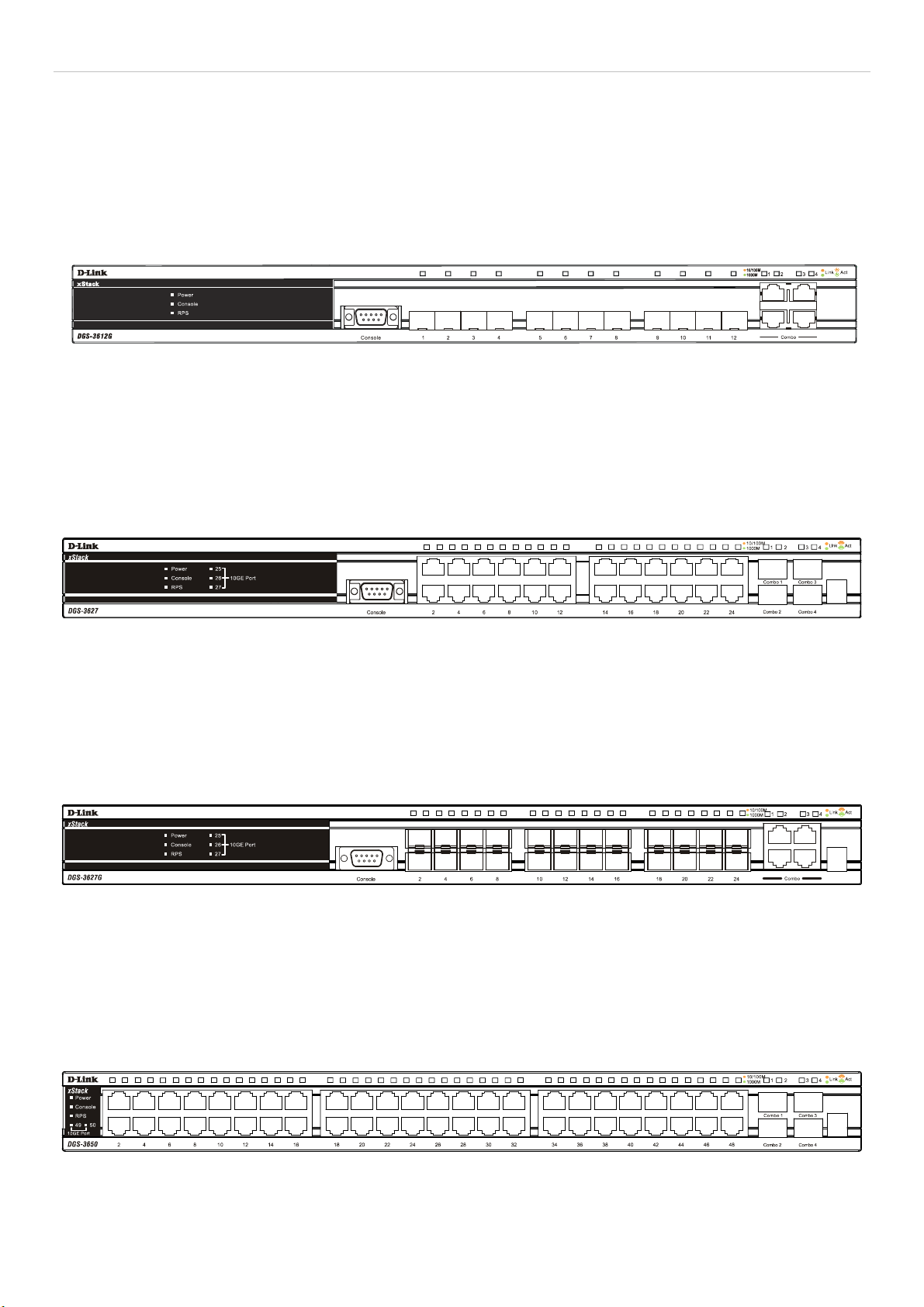
xStack DGS-3600 Series Layer 3 Gigabit Ethernet Managed Switch
Front-Panel Components
DGS-3612G
• Twelve SFP 100/1000Mbps ports
• Four Combo 1000BASE-T ports located to the right
• One female DCE RS -232 DB-9 console port
• LEDs for Power, Console, RPS, and Link/Act/Speed for each port
Figure 1- 1. Front Panel of the DGS-3612GG
DGS-3627
• Twenty-four 10/100/1000BASE-T ports
• Four Combo SFP ports located to the right
• One female DCE RS-232 DB-9 console port
• LEDs for Power, Console, RPS, Link/Act/Speed and 10GE for each port
• Stacking Module Numbered LED
Figure 1- 2. Front Panel of the DGS-3627
DGS-3627G
• Twenty-four SFP 1000Mbps ports
• Four Combo 1000BASE-T ports located to the right
• One female DCE RS -232 DB-9 console port
• LEDs for Power, Console, RPS, Link/Act/Speed and 10GE for each port
• Stacking Module Numbered LED
Figure 1- 3. Front Panel of the DGS-3627G
DGS-3650
• Forty-eight 10/100/1000BASE-T ports
• Four Combo SFP ports located to the right
• One female DCE RS -232 DB-9 console port
• LEDs for Power, Console, RPS, Link/Act/Speed and 10GE for each port
• Stacking Module Numbered LED
Figure 1- 4. Front Panel of the DGS-3650
2
Page 20
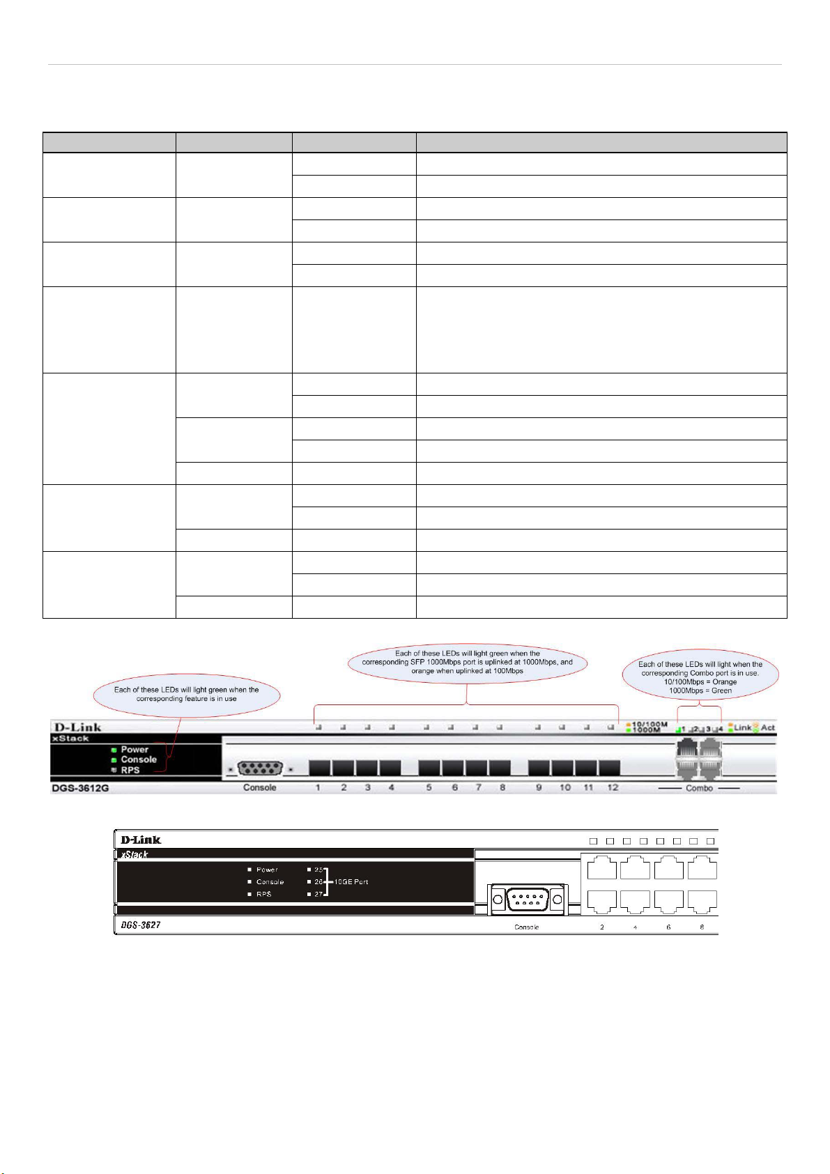
xStack DGS-3600 Series Layer 3 Gigabit Ethernet Managed Switch
LEDs
The following table lists the LEDs located on models of the xStack DGS-3600 switch along with their corresponding description:
LED Indicator Color Status Description
Power
Console
RPS
Stacking LED (To
be supported in
Release II)
Port LEDs
(10/100/1000Mbps
ports)
SFP Port LED
10GE Module
LEDs (Located on
the front panel)
Green
Green
Green
Green Numbered 1-12
Dark No Light Link Down
Dark No Light Link Down
Dark No Light Link Down
Solid Power On
Dark Power Off
Solid Console On
Dark Console Off
Solid RPS in use
Dark RPS not in use or not present
Box ID of the Switch in the switch stack. This field will
read 1 for a switch in standalone mode. When the switch
in question is a master of a switch stack, the number of
the switch in the stack will be displayed, and the letter H
will flash alternatively with this number.
Solid Denotes an active connection at 1000Mbps. Green
Blinking Denotes data transfer at 1000Mbps.
Solid Denotes an active connection at 10/100Mbps. Orange
Blinking Denotes data transfer at 10/100Mbps.
Solid Denotes an active connection at 1000Mbps. Green
Blinking Denotes data transfer at 1000Mbps.
Solid Denotes an active connection. Green
Blinking Denotes data transfer.
Figure 1- 5. DGS-3612G LEDs
Figure 1- 6. DGS-3627 LEDs
3
Page 21
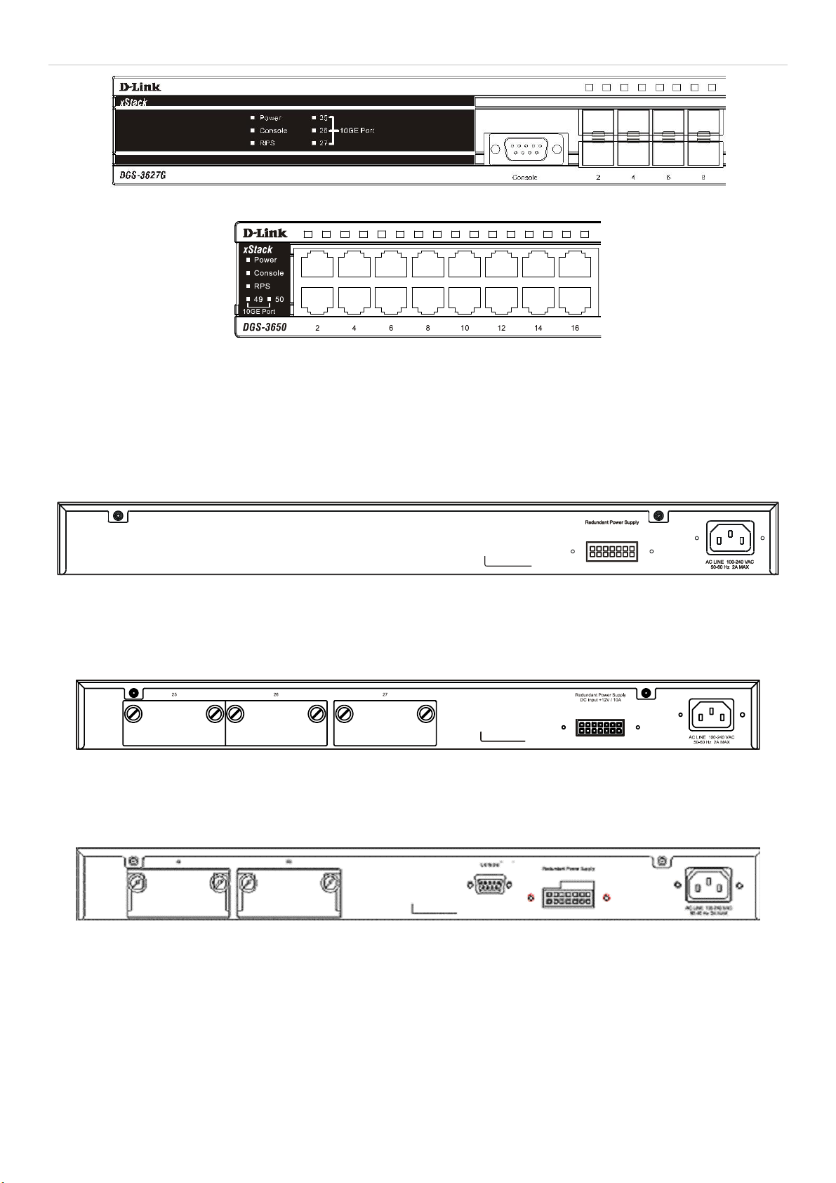
xStack DGS-3600 Series Layer 3 Gigabit Ethernet Managed Switch
Figure 1- 7. DGS-3627G LEDs
Figure 1- 8. DGS-3650 LEDs
Rear Panel Description
The rear panels of the DGS-3612G, DGS-3627, DGS-3627G and the DGS-3650 are described below.
DGS-3612G
The rear panel of the DGS-3612G contains an AC power connector, and an outlet for an optional external RPS.
Figure 1- 9. Rear panel view of the DGS-3612G
DGS-3627 and DGS-3627G
The rear panel of DGS-3627 and DGS-3627G contains an AC power connector, an outlet for an optional external RPS and three
slots for additional 10GE optional modules.
Figure 1- 10. Rear panel view of the DGS-3627(G)
DGS-3650
The rear panel of DGS-3650 contains an AC power connector, an outlet for an optional external RPS, a DCE RS-232 console port
and two slots for additional 10GE optional modules.
Figure 1- 11. Rear Panel view of DGS-3650
The rear panel includes an outlet for an optional external redundant power supply. When power fails, the optional external RPS
will take over all the power immediately and automatically. The AC power connector is a standard three-pronged connector that
supports the power cord. Plug-in the female connector of the provided power cord into this socket, and the male side of the cord
into a power outlet. The Switch automatically adjusts its power setting to any supply voltage in the range from 100 ~ 240 VAC at
50 ~ 60 Hz.
4
Page 22
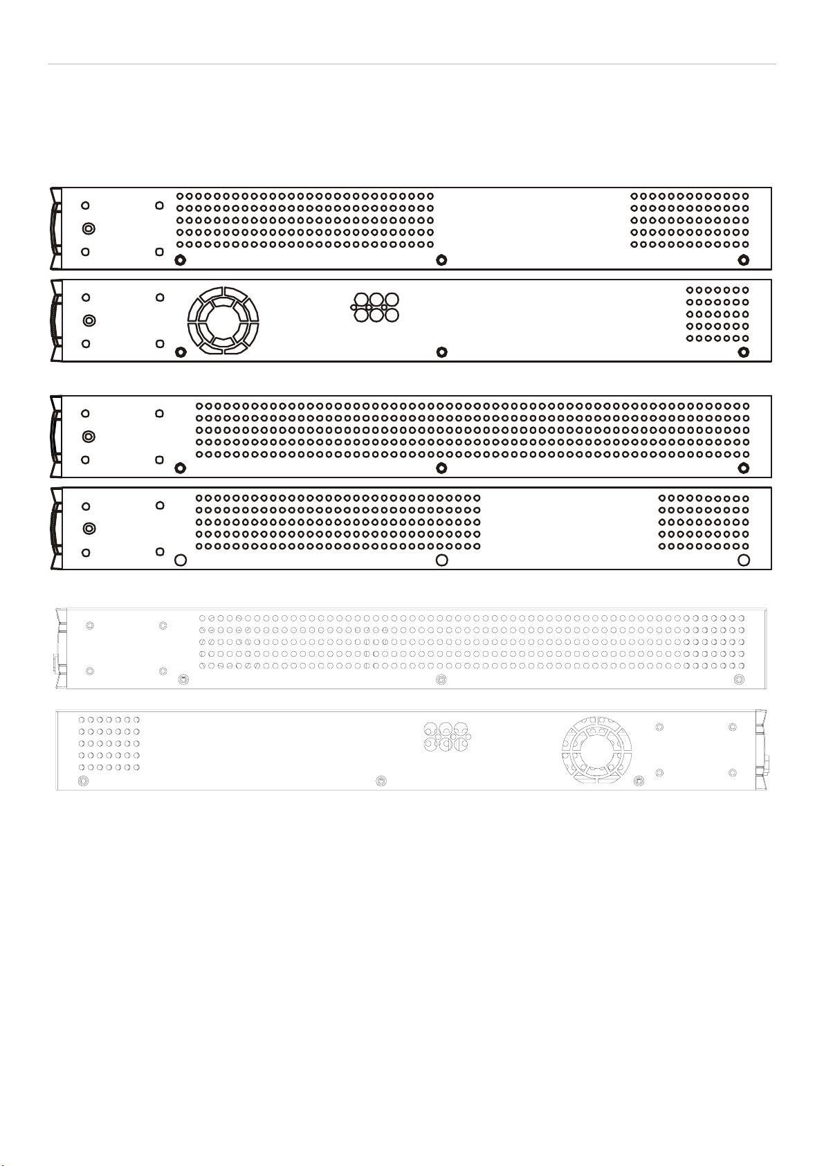
xStack DGS-3600 Series Layer 3 Gigabit Ethernet Managed Switch
Side Panel Description
The right-hand side panel of the Switch contains a system fan and ventilation along the entire right side. The left hand panel
includes a system fan and a heat vent. The system fans are used to dissipate heat. Do not block these openings on either side of the
Switch. Leave at least 6 inches of space at the rear and sides of the Switch for proper ventilation. Be reminded that without proper
heat dissipation and air circulation, system components might overheat, which could lead to system failure.
Figure 1- 12. Side Panels of the DGS-3627 and the DGS-3627G
Figure 1- 13. Side Panels of the DGS-3650
Figure 1- 14. Side Panels of the DGS-3612G
5
Page 23
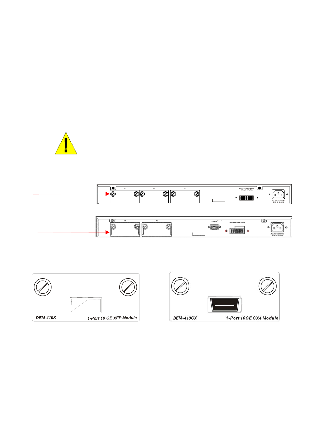
xStack DGS-3600 Series Layer 3 Gigabit Ethernet Managed Switch
10GE Uplink Modules
At the rear of the xStack DGS-3600 series switches reside optional module slots. This slot may be equipped with the DEM-410X
single-port 10GE XFP uplink module, or a DEM-410CX single-port 10GE CX4 uplink module, both sold separately.
Adding the DEM-410X optional module will allow the administrator to add a single-port 10GE stacking module which will
transmit information at a rate of ten gigabits a second. This port is compliant with standard IEEE 802.3ae, supports full-duplex
transmissions only and is to be used with XFP MSA compliant transceivers.
The DEM-410CX will too transfer information at a rate of ten gigabits a second but is used as an uplink module to a network
device. Compliant with the IEEE802.3ak standard, this module will use a 4-laned copper connector to transfer information in fullduplex mode, quickly and accurately. User beware, the cable and connector port used for this module is nearly identical to the
stacking ports and cables used for stacking in the xStack Series, but can in no way be interchangeable.
To install these modules, follow the simple steps listed below.
CAUTION: Before adding the optional module, make sure to disconnect all
power sources connected to the Switch. Failure to do so may result in an
electrical shock, which may cause damage, not only to the individual but to
At the back of the Switch to the left is the slot for the optional module, as shown in Figure 1-15 and Figure 1-16. This slot should
be covered with a faceplate that can be easily removed by loosening the screws and pulling off the plate.
Optional Module Slots
the Switch as well.
Figure 1- 15. Optional Module slots at the rear of the DGS-3627 (or DGS-3627G)
Optional Module Slots
Figure 1- 16. Optional Module slots at the rear of the DGS-3650
After removing the faceplate, remove the DEM-410X or DEM-410CX optional module from its box. The front panel should
resemble the drawings represented here.
Figure 1- 17. Front Panel of the DEM-410X and the DEM-410CX
Take the module and gently slide it in to the available slot at the rear of the Switch until it reaches the back, as shown in the
following figure. At the back of the slot are two sets of plugs that must be connected to the module. Gently, but firmly push in on
the module to secure it to the Switch. The module should fit snugly into the corresponding receptors.
6
Page 24
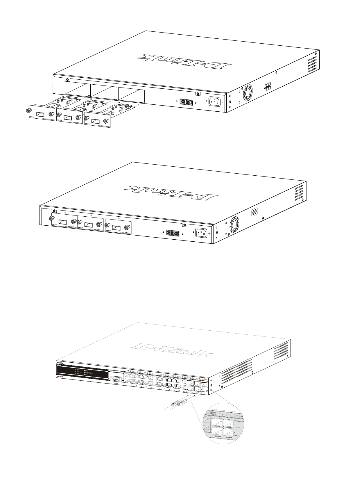
xStack DGS-3600 Series Layer 3 Gigabit Ethernet Managed Switch
Figure 1- 18. Inserting the optional modules into the Switch.
Now tighten the two screws at adjacent ends of the module into the available screw holes on the Switch. The upgraded DGS3627/DGS-3627G/DGS-3650 is now ready for use.
Figure 1- 19. DGS-3627 with optional module installed.
Installing the SFP ports
The xStack DGS-3600 Series switches are equipped with SFP (Small Form Factor Portable) ports, which are to be used with
fiber-optical transceiver cabling in order to uplink various other networking devices for a gigabit link that may span great
distances. These SFP ports support full-duplex transmissions, have auto-negotiation and can be used with the DEM-310GT
(1000BASE-LX), DEM-311GT (1000BASE-SX), DEM-312GT2 (1000BASE-LX), DEM-314GT (1000BASE-LH), DEM-315GT
(1000BASE-ZX), DEM-330T/R (WDM) and DEM-331T/R (WDM)transceivers. See the figure below for installing the SFP ports
in the Switch.
Figure 1- 20. Inserting the fiber-optic transceivers into the DGS-3600 series switch
7
Page 25

xStack DGS-3600 Series Layer 3 Gigabit Ethernet Managed Switch
SECTION 2
Installation
Package Contents
Before You Connect to the Network
Installing the Switch without the Rack
Rack Installation
Power On
RPS Installation
Package Contents
Open the shipping carton of the Switch and carefully unpack its contents. The carton should contain the following items:
One Stand-alone Switch •
•
One AC power cord
•
This Manual on CD
•
Mounting kit (two brackets and screws)
•
Four rubber feet with adhesive backing
•
DCE RS-232 console cable
If any item is missing or damaged, please contact your local D-Link Reseller for replacement.
Before You Connect to the Network
The site where you install the Switch may greatly affect its performance. Please follow these guidelines for setting up the Switch.
•
Install the Switch on a sturdy, level surface that can support at least 4.24kg (9.35lbs) of weight for the DGS3612G/DGS-3627/DGS-3627G, or 6.02kg (13.27lbs) for DGS-3650. Do not place heavy objects on the Switch.
•
The power outlet should be within 1.82 meters (6 feet) of the Switch.
•
Visually inspect the power cord and see that it is fully secured to the AC/DC power port.
•
Make sure that there is proper heat dissipation from and adequate ventilation around the Switch. Leave at least 10 cm
(4 inches) of space at the front and rear of the Switch for ventilation.
•
Install the Switch in a fairly cool and dry place for the acceptable temperature and humidity operating ranges.
•
Install the Switch in a site free from strong electromagnetic field generators (such as motors), vibration, dust, and
direct exposure to sunlight.
•
When installing the Switch on a level surface, attach the rubber feet to the bottom of the device. The rubber feet
cushion the Switch, protect the casing from scratches and prevent it from scratching other surfaces.
8
Page 26
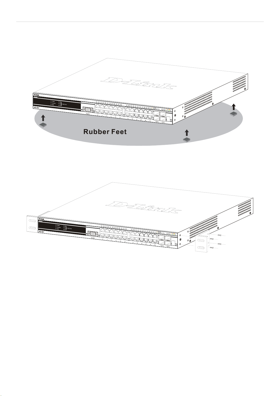
xStack DGS-3600 Series Layer 3 Gigabit Ethernet Managed Switch
Installing the Switch without the Rack
When installing the Switch on a desktop or shelf, the rubber feet included with the Switch should first be attached. Attach these
cushioning feet on the bottom at each corner of the device. Allow enough ventilation space between the Switch and any other
objects in the vicinity.
Figure 2 - 1. Prepare Switch for installation on a desktop or shelf
Installing the Switch in a Rack
The Switch can be mounted in a standard 19" rack. Use the following diagrams to guide you.
Figure 2 - 2. Fasten mounting brackets to Switch
Fasten the mounting brackets to the Switch using the screws provided. With the brackets attached securely, users can mount the
Switch in a standard rack as shown in Figure 2-3 below.
9
Page 27
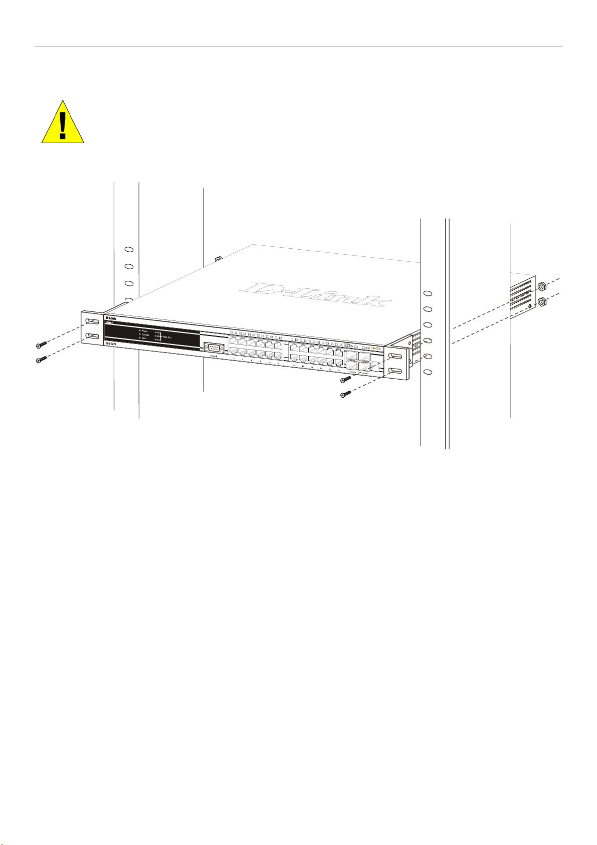
xStack DGS-3600 Series Layer 3 Gigabit Ethernet Managed Switch
Mounting the Switch in a Standard 19" Rack
CAUTION: Installing systems in a rack without the front and side stabilizers installed could cause the
rack to tip over, potentially resulting in bodily injury under certain circumstances. Therefore, always
install the stabilizers before installing components in the rack. After installing components in a rack, do
not pull more than one component out of the rack on its slide assemblies at one time. The weight of
more than one extended component could cause the rack to tip over and may result in injury.
Figure 2 - 3. Installing Switch in a rack
Power on AC Power
Plug one end of the AC power cord into the power connector of the Switch and the other end into the local power source outlet.
After the Switch is powered on, the LED indicators will momentarily blink. This blinking of the LED indicators represents a reset
of the system.
Power Failure
For AC power supply units, as a precaution, in the event of a power failure, unplug the Switch. When power has resumed, plug the
Switch back in.
10
Page 28
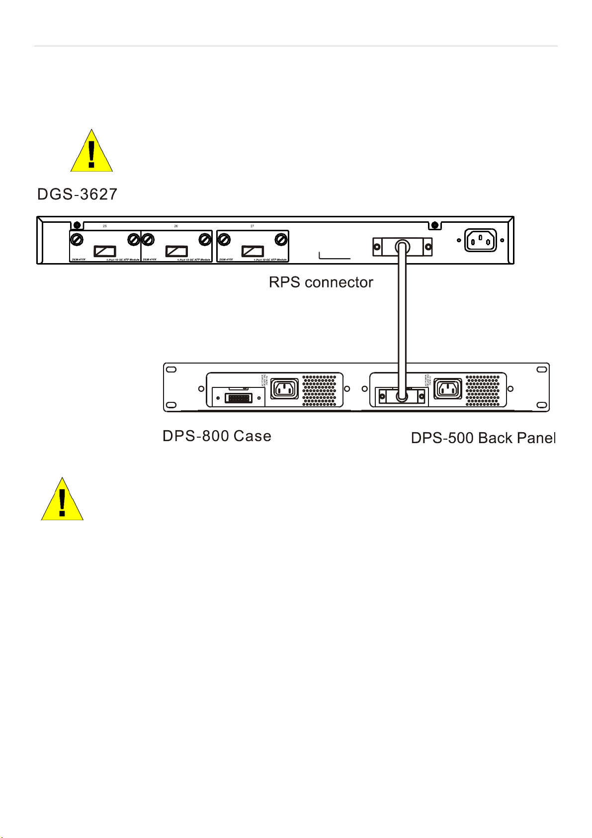
xStack DGS-3600 Series Layer 3 Gigabit Ethernet Managed Switch
RPS Installation
Follow the instructions below to connect an RPS power supply to the Switch (DPS-500). The DPS-500 is a redundant powersupply unit designed to conform to the voltage requirements of the switches being supported. DPS-500 can be installed into the
DPS-900, or DPS-800.
CAUTION: The AC power cord for the Switch should be disconnected before proceeding
with installation of the DPS-500.
Figure 2 - 4. Installing the DPS-500
CAUTION: Installing systems in a rack without the front and side stabilizers installed could cause the
rack to tip over, potentially resulting in bodily injury under certain circumstances. Therefore, always
install the stabilizers before installing components in the rack. After installing components in a rack, do
not pull more than one component out of the rack on its slide assemblies at one time. The weight of
more than one extended component could cause the rack to tip over and may result in injury.
11
Page 29
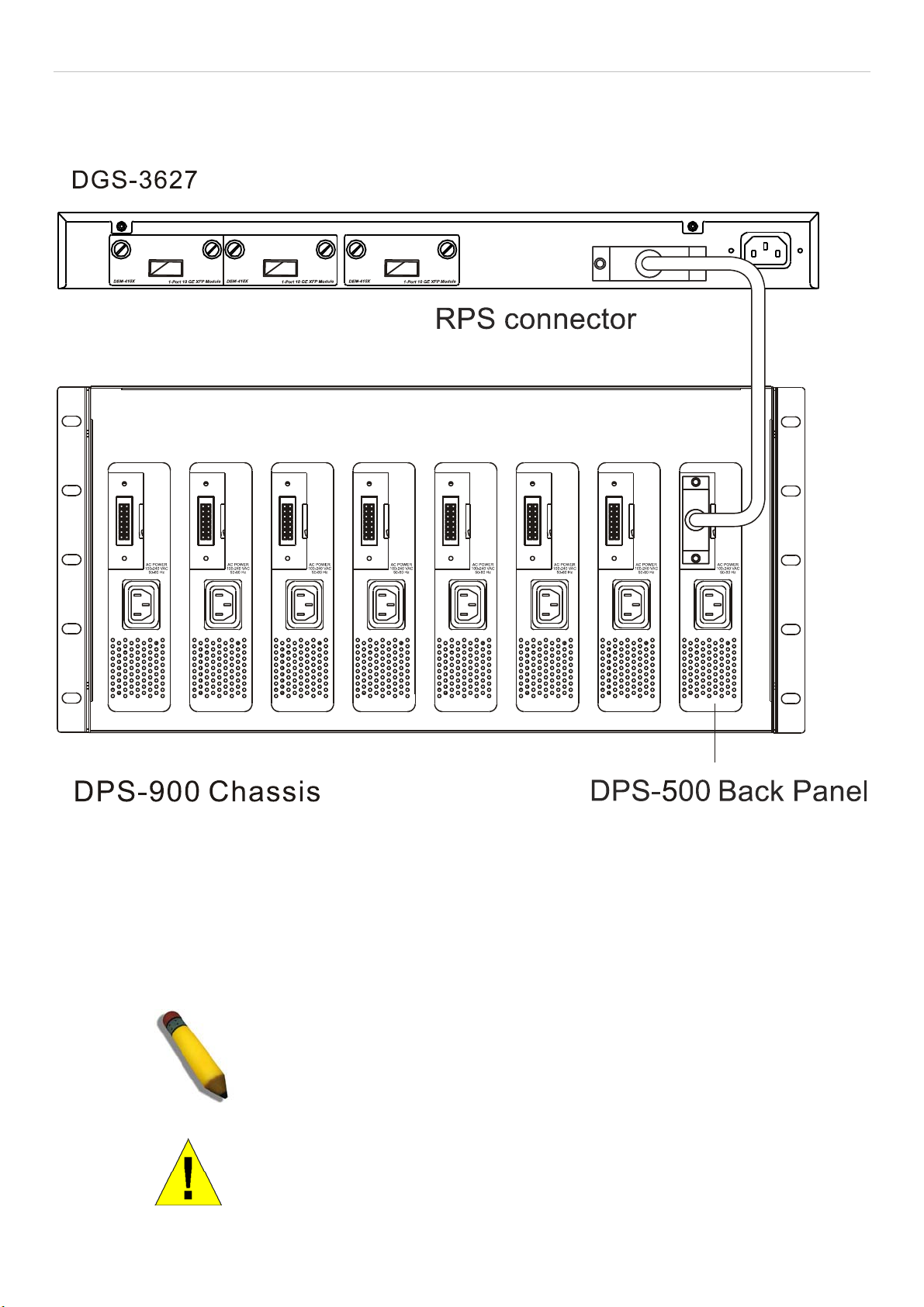
xStack DGS-3600 Series Layer 3 Gigabit Ethernet Managed Switch
Connect to RPS
The DPS-200 is connected to the Master Switch using a 14-pin DC power cable. A standard, three-pronged AC power cable
connects the redundant power supply to the main power source.
Figure 2 - 5. The DGS-3627 with the DPS-500 chassis RPS
1. Insert one end of the 14-pin DC power cable into the receptacle on the switch and the other end into the redundant power
supply.
2. Using a standard AC power cable, connect the redundant power supply to the main AC power source. A green LED on the
front of the DPS-500 will glow to indicate a successful connection.
3. Re-connect the switch to the AC power source. A LED indicator will show that a redundant power supply is now in
operation.
4. No change in switch configuration is necessary for this installation.
NOTE: See the DPS-500 documentation for more information.
CAUTION: Do not use the Switch with any redundant power system other
than the DPS-500.
12
Page 30
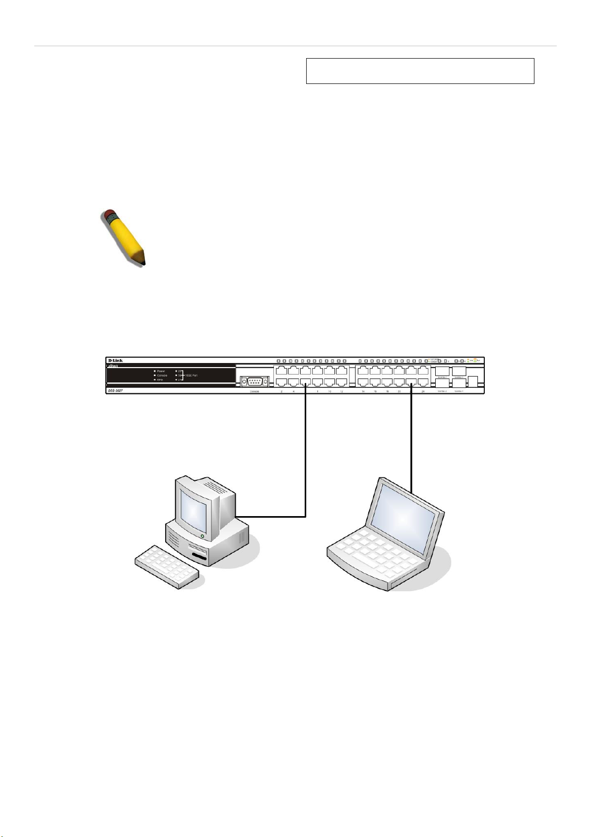
xStack DGS-3600 Series Layer 3 Gigabit Ethernet Managed Switch
Section 3
Connecting the Switch
Switch to End Node
Switch to Hub or Switch
Connecting to Network Backbone or Server
NOTE: All 10/100/1000Mbps NWay Ethernet ports can support both MDIII and MDI-X connections.
Switch to End Node
End nodes include PCs outfitted with a 10, 100 or 1000 Mbps RJ 45 Ethernet/Fast Ethernet Network Interface Card (NIC) and
most routers. An end node can be connected to the Switch via a twisted-pair Category 3, 4, or 5 UTP/STP cable. The end node
should be connected to any of the ports of the Switch.
Figure 3- 1. Switch connected to an end node
The Link/Act LEDs for each UTP port will light green or amber when the link is valid. A blinking LED indicates packet activity
on that port.
13
Page 31

xStack DGS-3600 Series Layer 3 Gigabit Ethernet Managed Switch
Switch to Hub or Switch
These connections can be accomplished in a number of ways using a normal cable.
A 10BASE-T hub or switch can be connected to the Switch via a twisted-pair Category 3, 4 or 5 UTP/STP cable. •
•
A 100BASE-TX hub or switch can be connected to the Switch via a twisted-pair Category 5 UTP/STP cable.
•
A 1000BASE-T switch can be connected to the Switch via a twisted pair Category 5e UTP/STP cable.
•
A switch supporting a fiber-optic uplink can be connected to the Switch’s SFP ports via fiber-optic cabling.
Figure 3- 2. Switch connected to a normal (non-Uplink) port on a hub or switch using a straight or crossover
cable
NOTICE: When the SFP transceiver acquires a link, the associated integrated
10/100/1000BASE-T port is disabled.
14
Page 32

xStack DGS-3600 Series Layer 3 Gigabit Ethernet Managed Switch
Connecting To Network Backbone or Server
The two Mini-GBIC combo ports are ideal for uplinking to a network backbone or server. The copper ports operate at a speed of
1000, 100 or 10Mbps in full duplex mode. The fiber optic ports can operate at 1000Mbps in full duplex mode. Connections to the
Gigabit Ethernet ports are made using fiber optic cable or Category 5 copper cable, depending on the type of port. A valid
connection is indicated when the Link LED is lit.
Figure 3- 3. Uplink Connection to a server, PC or switch stack.
15
Page 33

xStack DGS-3600 Series Layer 3 Gigabit Ethernet Managed Switch
Section 4
Introduction to Switch Management
Management Options
Web-based Management Interface
SNMP-Based Management
Managing User Accounts
Command Line Console Interface through the Serial Port
Connecting the Console Port (RS-232 DCE)
First Time Connecting to the Switch
Password Protection
SNMP Settings
IP Address Assignment
Management Options
This system may be managed out-of-band through the console port on the front panel or in-band using Telnet. The user may also
choose the web-based management, accessible through a web browser.
Web-based Management Interface
After you have successfully installed the Switch, you can configure the Switch, monitor the LED panel, and display statistics
graphically using a web browser, such as Netscape Navigator (version 6.2 and higher) or Microsoft® Internet Explorer (version
5.0).
SNMP-Based Management
You can manage the Switch with an SNMP-compatible console program. The Switch supports SNMP version 1.0, version 2.0 and
version 3.0. The SNMP agent decodes the incoming SNMP messages and responds to requests with MIB objects stored in the
database. The SNMP agent updates the MIB objects to generate statistics and counters.
Connecting the Console Port (RS-232 DCE)
The Switch provides an RS-232 serial port that enables a connection to a computer or terminal for monitoring and configuring the
Switch. This port is a female DB-9 connector, implemented as a data terminal equipment (DTE) connection.
To use the console port, you need the following equipment:
A terminal or a computer with both a serial port and the ability to emulate a terminal. •
• A null modem or crossover RS-232 cable with a female DB-9 connector for the console port on the Switch.
To connect a terminal to the console port:
1. Connect the female connector of the RS-232 cable directly to the console port on the Switch, and tighten the captive
retaining screws.
2. Connect the other end of the cable to a terminal or to the serial connector of a computer running terminal emulation
software. Set the terminal emulation software as follows:
3. Select the appropriate serial port (COM port 1 or COM port 2).
4. Set the data rate to 115200 baud.
5. Set the data format to 8 data bits, 1 stop bit, and no parity.
6. Set flow control to none.
16
Page 34

xStack DGS-3600 Series Layer 3 Gigabit Ethernet Managed Switch
7. Under Properties, select VT100 for Emulation mode.
8. Select Terminal keys for Function, Arrow, and Ctrl keys. Ensure that you select Terminal keys (not Windows keys).
NOTE: When you use HyperTerminal with the Microsoft® Windows® 2000 operating system, ensure that you have Windows 2000 Service Pack 2 or later installed. Windows 2000
Service Pack 2 allows you to use arrow keys in HyperTerminal's VT100 emulation. See
www.microsoft.com for information on Windows 2000 service packs.
9. After you have correctly set up the terminal, plug the power cable into the power receptacle on the back of the Switch.
The boot sequence appears in the terminal.
10. After the boot sequence completes, the console login screen displays.
11. If you have not logged into the command line interface (CLI) program, press the Enter key at the User name and
password prompts. There is no default user name and password for the Switch. The administrator must first create user
names and passwords. If you have previously set up user accounts, log in and continue to configure the Switch.
12. Enter the commands to complete your desired tasks. Many commands require administrator-level access privileges. Read
the next section for more information on setting up user accounts. See the xStack DGS-3600 Series CLI Manual on the
documentation CD for a list of all commands and additional information on using the CLI.
13. When you have completed your tasks, exit the session with the logout command or close the emulator program.
14. Make sure the terminal or PC you are using to make this connection is configured to match these settings.
If you are having problems making this connection on a PC, make sure the emulation is set to VT-100. You will be able to set the
emulation by clicking on the File menu in you HyperTerminal window, clicking on Properties in the drop-down menu, and then
clicking the Settings tab. This is where you will find the Emulation options. If you still do not see anything, try rebooting the
Switch by disconnecting its power supply.
Once connected to the console, the screen below will appear on your console screen. This is where the user will enter commands
to perform all the available management functions. The Switch will prompt the user to enter a user name and a password. Upon
the initial connection, there is no user name or password and therefore just press enter twice to access the command line interface.
Figure 4- 1. Initial screen after first connection
17
Page 35

xStack DGS-3600 Series Layer 3 Gigabit Ethernet Managed Switch
First Time Connecting to the Switch
The Switch supports user-based security that can allow you to prevent unauthorized users from accessing the Switch or changing
its settings. This section tells how to log onto the Switch.
NOTE: The passwords used to access the Switch are case-sensitive; therefore, "S" is
not the same as "s."
When you first connect to the Switch, you will be presented with the first login screen.
NOTE: Press Ctrl+R to refresh the screen. This command can be used at any time to
force the console program in the Switch to refresh the console screen.
Press Enter in both the Username and Password fields. You will be given access to the command prompt DGS-3600:4# shown
below:
There is no initial username or password. Leave the Username and Password fields blank.
Figure 4- 2. Command Prompt
NOTE: The first user automatically gets Administrator level privileges. It is recommended to
create at least one Admin-level user account for the Switch.
Password Protection
The Switch does not have a default user name and password. One of the first tasks when settings up the Switch is to create user
accounts. Once logged in using a predefined administrator-level user name, users will have privileged access to the Switch's
management software.
After your initial login, define new passwords for both default user names to prevent unauthorized access to the Switch, and
record the passwords for future reference.
To create an administrator-level account for the Switch, follow these steps:
At the CLI login prompt, enter create account admin followed by the <user name> and press the Enter key. •
18
Page 36

xStack DGS-3600 Series Layer 3 Gigabit Ethernet Managed Switch
The switch will then prompt the user for a password. Type the <password> used for the administrator account being
•
created and press the Enter key.
•
Again, the user will be prompted to enter the same password again to verify it. Type the same password and press
the Enter key.
•
Successful creation of the new administrator account will be verified by a Success message.
NOTE: Passwords are case sensitive. User names and passwords can be
up to 15 characters in length.
The sample below illustrates a successful creation of a new administrator-level account with the user name "newmanager".
DGS-3600:4#create account admin newmanager
Command: create account admin newmanager
Enter a case-sensitive new password:********
Enter the new password again for confirmation:********
Success.
DGS-3600:4#
NOTICE: CLI configuration commands only modify the running configuration file
and are not saved when the Switch is rebooted. To save all your configuration
changes in nonvolatile storage, you must use the save command to copy the
running configuration file to the startup configuration.
SNMP Settings
Simple Network Management Protocol (SNMP) is an OSI Layer 7 (Application Layer) designed specifically for managing and
monitoring network devices. SNMP enables network management stations to read and modify the settings of gateways, routers,
switches, and other network devices. Use SNMP to configure system features for proper operation, monitor performance and
detect potential problems in the Switch, switch group or network.
Managed devices that support SNMP include software (referred to as an agent), which runs locally on the device. A defined set of
variables (managed objects) is maintained by the SNMP agent and used to manage the device. These objects are defined in a
Management Information Base (MIB), which provides a standard presentation of the information controlled by the on-board
SNMP agent. SNMP defines both the format of the MIB specifications and the protocol used to access this information over the
network.
The DGS-3600 Series supports SNMP versions 1, 2c, and 3. You can specify which version of SNMP you want to use to monitor
and control the Switch. The three versions of SNMP vary in the level of security provided between the management station and
the network device.
In SNMP v.1 and v.2, user authentication is accomplished using 'community strings', which function like passwords. The remote
user SNMP application and the Switch SNMP must use the same community string. SNMP packets from any station that has not
been authenticated are ignored (dropped).
The default community strings for the Switch used for SNMP v.1 and v.2 management access are:
public - Allows authorized management stations to retrieve MIB objects. •
• private - Allows authorized management stations to retrieve and modify MIB objects.
SNMP v.3 uses a more sophisticated authentication process that is separated into two parts. The first part is to maintain a list of
users and their attributes that are allowed to act as SNMP managers. The second part describes what each user on that list can do
as an SNMP manager.
The Switch allows groups of users to be listed and configured with a shared set of privileges. The SNMP version may also be set
for a listed group of SNMP managers. Thus, you may create a group of SNMP managers that are allowed to view read-only
19
Page 37
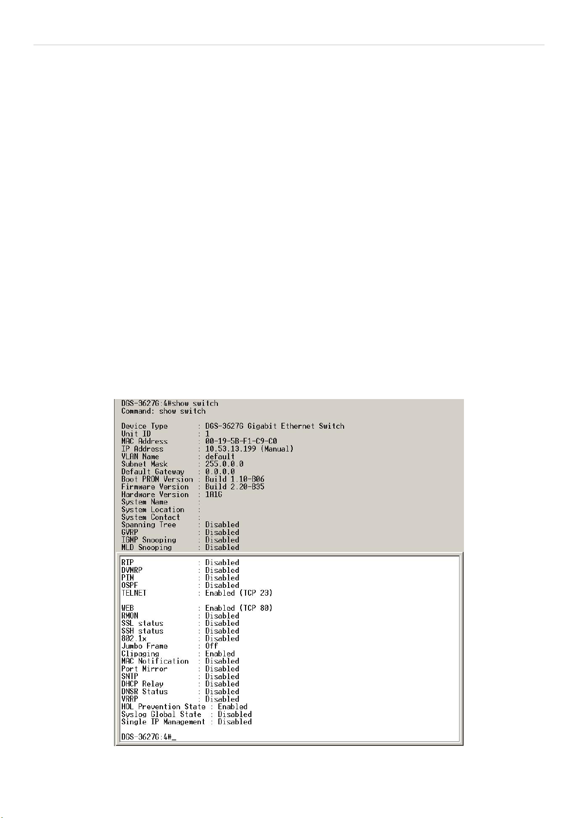
xStack DGS-3600 Series Layer 3 Gigabit Ethernet Managed Switch
information or receive traps using SNMP v.1 while assigning a higher level of security to another group, granting read/write privileges using SNMP v.3.
Using SNMP v.3 individual users or groups of SNMP managers can be allowed to perform or be restricted from performing
specific SNMP management functions. The functions allowed or restricted are defined using the Object Identifier (OID)
associated with a specific MIB. An additional layer of security is available for SNMP v.3 in that SNMP messages may be
encrypted. To read more about how to configure SNMP v.3 settings for the Switch read the section entitled Management.
Traps
Traps are messages that alert network personnel of events that occur on the Switch. The events can be as serious as a reboot
(someone accidentally turned OFF the Switch), or less serious like a port status change. The Switch generates traps and sends
them to the trap recipient (or network manager). Typical traps include trap messages for Authentication Failure, Topology Change
and Broadcast\Multicast Storm.
MIBs
The Switch in the Management Information Base (MIB) stores management and counter information. The Switch uses the
standard MIB-II Management Information Base module. Consequently, values for MIB objects can be retrieved from any SNMPbased network management software. In addition to the standard MIB-II, the Switch also supports its own proprietary enterprise
MIB as an extended Management Information Base. Specifying the MIB Object Identifier may also retrieve the proprietary MIB.
MIB values can be either read-only or read-write.
IP Address Assignment
Each Switch must be assigned its own IP Address, which is used for communication with an SNMP network manager or other
TCP/IP application (for example BOOTP, TFTP). The Switch's default IP address is 10.90.90.90. You can change the default
Switch IP address to meet the specification of your networking address scheme.
The Switch is also assigned a unique MAC address by the factory. This MAC address cannot be changed, and can be found by
entering the command "show switch" into the command line interface, as shown below.
Figure 4- 3. Show switch command
20
Page 38

xStack DGS-3600 Series Layer 3 Gigabit Ethernet Managed Switch
The Switch's MAC address can also be found from the Web management program on the Switch Information (Basic Settings)
window on the Configuration menu.
The IP address for the Switch must be set before it can be managed with the Web-based manager. The Switch IP address can be
automatically set using BOOTP or DHCP protocols, in which case the actual address assigned to the Switch must be known.
The IP address may be set using the Command Line Interface (CLI) over the console serial port as follows:
Starting at the command line prompt, enter the commands
config ipif System ipaddress xxx.xxx.xxx.xxx/yyy.yyy.yyy.yyy
Where the x's represent the IP address to be assigned to the IP interface named System and the y's represent the corresponding
subnet mask.
Alternatively, you can enter config ipif System ipaddress xxx.xxx.xxx.xxx/z. Where the x's represent the IP address to be
assigned to the IP interface named System and the z represents the corresponding number of subnets in CIDR notation.
The IP interface named System on the Switch can be assigned an IP address and subnet mask, and then be used to connect a
management station to the Switch's Telnet or Web-based management agent.
Figure 4- 4. Assigning the Switch an IP Address
In the above example, the Switch was assigned an IP address of 10.53.13.65 with a subnet mask of 255.0.0.0. The user may also
use the CIDR form to set the address (10.53.13.65/8). The system message Success indicates that the command was executed
successfully. The Switch can now be configured and managed via Telnet and the CLI or via the Web-based management.
21
Page 39

xStack DGS-3600 Series Layer 3 Gigabit Ethernet Managed Switch
Section 5
Web-based Switch Configuration
Introduction
Login to Web manager
Web-Based User Interface
Web Pages
Introduction
All software functions of the Switch can be managed, configured and monitored via the embedded web-based (HTML) interface.
The Switch can be managed from remote stations anywhere on the network through a standard browser such as Opera, Netscape
Navigator/Communicator, or Microsoft Internet Explorer. The browser acts as a universal access tool and can communicate
directly with the Switch using the HTTP protocol.
The Web-based management module and the Console program (and Telnet) are different ways to access the same internal
switching software and configure it. Thus, all settings encountered in web-based management are the same as those found in the
console program.
Login to Web Manager
To begin managing the Switch, simply run the browser you have installed on your computer and point it to the IP address you
have defined for the device. The URL in the address bar should read something like: http://123.123.123.123, where the numbers
123 represent the IP address of the Switch.
NOTE: The Factory default IP address for the Switch is 10.90.90.90.
This opens the management module's user authentication window, as seen below.
Figure 5- 1. Enter Network Password window
Leave both the User Name field and the Password field blank and click OK. This will open the Web-based user interface. The
Switch management features available in the web-based manager are explained below.
22
Page 40

xStack DGS-3600 Series Layer 3 Gigabit Ethernet Managed Switch
Web-based User Interface
The user interface provides access to various Switch configuration and management screens, allows you to view performance
statistics, and permits you to graphically monitor the system status.
Areas of the User Interface
The figure below shows the user interface. The user interface is divided into three distinct areas as described in the table.
Area 2
Area 3
Area 1
Area Function
Area 1
Area 2
Select the menu or window to be displayed. The folder icons can be opened to display the hyperlinked menu buttons and subfolders contained within them. Click the D-Link logo to go to the D-Link
website.
Presents a graphical near real-time image of the front panel of the Switch. This area displays the
Switch's ports and expansion modules, showing port activity, duplex mode, or flow control,
depending on the specified mode.
Various areas of the graphic can be selected for performing management functions, including port
configuration.
Figure 5- 2. Main Web-Manager page
Area 3
Presents switch information based on your selection and the entry of configuration data.
NOTICE: Any changes made to the Switch configuration during the current
session must be saved in the Save Changes web menu (explained below)
or use the command line interface (CLI) command save.
23
Page 41

xStack DGS-3600 Series Layer 3 Gigabit Ethernet Managed Switch
Web Pages
When you connect to the management mode of the Switch with a web browser, a login window is displayed. Enter a user name
and password to access the Switch's management mode.
Below is a list and description of the main folders available in the web interface:
Administration – Contains windows concerning configuring the basic functions of the Switch, including Device Information, IP
Address, Port Configuration, User Accounts, Port Mirroring, System Log, System Severity Settings, SNTP Settings, MAC
Notification Settings, TFTP Services, File System Services, Ping Test, IPv6 Neighbor, DHCP Auto Configuration, SNMP
Manager, IP-MAC-Port Binding, sFlow and Single IP Management Settings.
Layer 2 Features – Contains windows concerning Layer 2 features of the Switch, including VLAN, Trunking, IGMP Snooping,
MLD Snooping, Spanning Tree and Forwarding & Filtering.
Layer 3 Features – A discussion of Layer 3 features of the Switch, including Interface Settings, MD5 Key Settings, Route
Redistribution Settings, Static/Default Route Settings, Route Preference Settings, Static ARP Settings, Policy Route Settings, RIP,
OSPF, DCHP/BOOTP Relay, DNS Relay, VRRP and IP Multicast Routing Protocol.
QoS – Contains windows concerning Bandwidth Control, QoS Scheduling Mechanism, QoS Output Scheduling, 802.1p Default
Priority and 802.1p User Priority.
ACL – Contains the window for Time Range, Access Profile Table, ACL Flow Meter and CPU Interface Filtering.
Security – Contains windows for Traffic Control, Port Security, 802.1X, Trust Host, Web Authentication, Trust Host, Access
Authentication Control, Safeguard Engine, Traffic Segmentation, SSL and SSH.
Monitoring – Contains windows for Device Status, Module Information, CPU Utilization, Port Utilization, Packets, Errors,
Packet Size, Browse Router Port, Browse MLD Router Port, VLAN Status, Port Access Control, MAC Address Table, IGMP
Snooping Group, MLD Snooping Group, Trace Route, IGMP Snooping Forwarding, MLD Snooping Forwarding, IP Forwarding
Table, Browse Routing Table, Browse IP Multicast Forwarding Table, Browse IP Multicast Interface Table, Browse IGMP Group
Table, DVMRP Monitor, PIM Monitor, OSPF Monitor, Switch Logs, Browse ARP Table and Session Table.
Switch Maintenance – Contains information regarding Reset System, Reboot, Logout and Save Services.
NOTE: Be sure to configure the user name and password in the User
Accounts menu before connecting the Switch to the greater network.
24
Page 42

xStack DGS-3600 Series Layer 3 Gigabit Ethernet Managed Switch
Administration
Device Information (DGS-3600 Web Management Tool)
Stacking
Port Configuration
User Accounts
Port Mirroring
System Log
System Severity Settings
SNTP Settings
MAC Notification Settings
TFTP Services
File System Services
Section 6
Ping Test
IPv6 Neighbor
DHCP Auto Configuration
SNMP Manager
IP-MA-Port Binding
sFlow
Single IP Management Setting
25
Page 43

xStack DGS-3600 Series Layer 3 Gigabit Ethernet Managed Switch
ging
w
y
d
k
n
Device Information
The Device Information window contains the main settings
for all major functions for the Switch and appears
automatically when you log on. To return to the Device
Information window, click the DGS-3600 Web
Management Tool folder. The Device Information windo
shows the Switch’s MAC Address (assigned by the factor
and unchangeable), the Boot PROM, Firmware Version, an
Hardware Version. This information is helpful to keep trac
of PROM and firmware updates and to obtain the Switch's
MAC address for entry into another network device's address
table, if necessary. The user may also enter a System Name,
System Location and System Contact to aid in defining the
Switch, to the user's preference. In addition, this scree
displays the status of functions on the Switch to quickly assess
their current global status. Some Functions are hyper-linked to
their configuration window for easy access from the Device
Information window.
Figure 6- 1. Device Information window
The fields that can be configured are described below:
Parameter Description
System Name Enter a system name for the Switch, if so desired. This name will identify it in the Switch
network.
System Location
System Contact
Serial Port Auto
Logout Time
Serial Baud Rate This field specifies the baud rate for the serial port on the Switch. There are four possible
MAC Address
Aging Time
Enter the location of the Switch, if so desired.
Enter a contact name for the Switch, if so desired.
Select the logout time used for the console interface. This automatically logs the user out after
an idle period of time, as defined. Choose from the following options: 2 Minutes, 5 Minutes, 10
Minutes, 15 Minutes or Never. The default setting is 10 minutes.
baud rates to choose from, 9600, 19200, 38400 and 115200. For a connection to the Switch
using the CLI interface, the baud rate must be set to 115200, which is the default setting.
This field specifies the length of time a learned MAC Address will remain in the forwarding
table without being accessed (that is, how long a learned MAC Address is allowed to remain
idle). To change this, type in a different value representing the MAC address age-out time in
seconds. The MAC Address A
Time can be set to any value between 10 and 1,000,000
26
Page 44

xStack DGS-3600 Series Layer 3 Gigabit Ethernet Managed Switch
pp
seconds. The default setting is 300 seconds.
IGMP Snooping To enable system-wide IGMP Snooping capability select Enabled. IGMP snooping is Disabled
by default. Enabling IGMP snooping allows you to specify use of a multicast router only (see
below). To configure IGMP Snooping for individual VLANs, use the IGMP Snooping located
in the IGMP Snooping folder contained in the L2 Features folder.
IGMP Multicast
Router Only
This field specifies that the Switch should only forward all multicast traffic to a multicastenabled router, if enabled. Otherwise, the Switch will forward all multicast traffic to any IP
router. The default is Disabled.
MLD Snooping
To enable system-wide MLD Snooping capability select Enabled. MLD snooping is Disabled
by default. Enabling MLD snooping allows you to specify use of a multicast router only (see
below). To configure MLD Snooping for individual VLANs, use the MLD Snooping window
under the MLD Snooping folder.
MLD Multicast
Router Only
This field specifies that the Switch should only forward all multicast traffic to a multicastenabled router, if enabled. Otherwise, the Switch will forward all multicast traffic to any IP
router. The default is Disabled.
GVRP Status
Use this pull-down menu to enable or disable GVRP on the Switch.
Telnet Status Telnet configuration is Enabled by default. If you do not want to allow configuration of the
system through Telnet choose Disabled.
Telnet TCP Port
Number (1-65535)
The TCP port number. TCP ports are numbered between 1 and 65535. The "well-known" TCP
port for the Telnet protocol is 23.
Web Status Web-based management is Enabled by default. If you choose to disable this by selecting
Disabled, you will lose the ability to configure the system through the web interface as soon as
these settings are applied.
Web TCP Port
Number (1-65535)
The web (GUI) port number. TCP ports are numbered between 1 and 65535. The "wellknown" TCP port for the Web protocol is 80.
RMON Status
Link Aggregation
Algorithm
Remote monitoring (RMON) of the Switch is Enabled or Disabled here.
The algorithm that the Switch uses to balance the load across the ports that make up the port
trunk group is defined by this definition. Choose MAC Source, MAC Destination, MAC Src &
Dest, IP Source, IP Destination or IP Src & Dest (See the Link Aggregation section of this
manual).
Switch 802.1X MAC Address may enable by port or the Switch’s 802.1X function; the default is Disabled.
This field must be enabled to view and configure certain windows for 802.1X. More
information regarding 802.1X, its functions and implementation can be found later in this
section, under the Port Access Entity folder.
Port-Based 802.1X specifies that ports configured for 802.1X are initialized based on the port
number only and are subject to any authorization parameters configured.
MAC-based Authorization specifies that ports configured for 802.1X are initialized based on
the port number and the MAC address of the computer being authorized and are then subject
to any authorization parameters configured.
Auth Protocol The 802.1X authentication protocol on the Switch is set to RADIUS Eap and cannot be
altered.
HOL Prevention
If this option is enabled it prevents the forwarding of data to a port that is blocked. Traffic that
would normally be sent to the buffer memory of the Switch’s TX queue is dropped so that
memory usage is conserved and performance across all ports remains high.
Jumbo Frame
This field will enable or disable the Jumbo Frame function on the Switch. The default is
Disabled. When enabled, jumbo frames (frames larger than the Ethernet frame size of 1536
bytes) of up to 9220 bytes (tagged) can be transmitted by the Switch.
Syslog State
ARP Aging Time (0-
65535)
Enables or disables Syslog State; default is Disabled.
The user may globally set the maximum amount of time, in minutes, that an Address
Resolution Protocol (ARP) entry can remain in the Switch’s ARP table, without being
accessed, before it is dro
ed from the table. The value may be set in the range of 0 to 65535
27
Page 45

xStack DGS-3600 Series Layer 3 Gigabit Ethernet Managed Switch
minutes with a default setting of 20 minutes.
DVMRP State The user may globally enable or disable the Distance Vector Multicast Routing Protocol
(DVMRP) function by using the pull down menu.
PIM-DM State The user may globally enable or disable the Protocol Independent Multicast - Dense Mode
(PIM-DM) function by using the pull down menu.
RIP State The user may globally enable or disable the Routing Information Protocol (RIP) function by
using the pull down menu.
OSPF State The user may globally enable or disable the Open Shortest Path first (OSPF) function by
using the pull down menu.
Click Apply to implement changes made.
28
Page 46
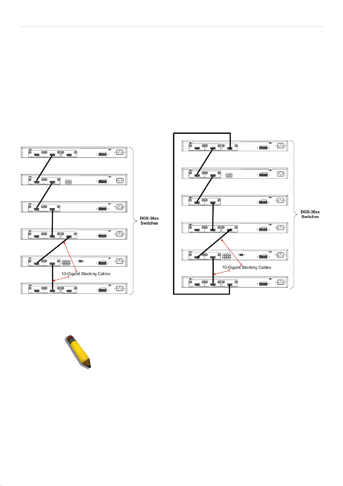
xStack DGS-3600 Series Layer 3 Gigabit Ethernet Managed Switch
Stacking
From firmware release v2.00 of this Switch, the xStack DGS-3600 Series now supports switch stacking, where a set of twelve
switches can be combined to be managed by one IP address through Telnet, the GUI interface (web), the console port or through
SNMP. Each switch of this series has either two or three stacking slots located at the rear of the device, which can be used to add
10-gigabit DEM-410CX or DEM-410X stacking modules, sold separately. After adding these stacking ports, the user may connect
these ports together using copper or fiber stacking cables (also sold separately) in one of two possible topologies.
Duplex Chain – As shown in Figure 6-2, The Duplex Chain topology stacks switches together in a chain-link format. Using this
method, data transfer is only possible in one direction and if there is a break in the chain, then data transfer will obviously be
affected.
Duplex Ring – As shown in Figure 6-3, the Duplex Ring stacks switches in a ring or circle format where data can be transferred
in two directions. This topology is very resilient due to the fact that if there is a break in the ring, data can still be transferred
through the stacking cables between switches in the stack.
Figure 6- 2. Switches stacked in a Duplex Chain Figure 6- 3. Switches stacked in a Duplex Ring
Within each of these topologies, each switch plays a role in the Switch stack. These roles can be set by the user per individual
Switch, or if desired, can be automatically determined by the switch stack. Three possible roles exist when stacking with the
xStack DGS-3600 series.
NOTE: Only ports 26 and 27 of the DGS-3627 support stacking. Port
25 cannot be used for stacking, and is to be used only as a 10Gigabit uplink port.
Primary Master – The Primary Master is the leader of the stack. It will maintain normal operations, monitor operations and the
running topology of the Stack. This switch will also assign Stack Unit IDs, synchronize configurations and transmit commands to
remaining switches in the switch stack. The Primary Master can be manually set by assigning this Switch the highest priority (a
lower number denotes a higher priority) before physically assembling the stack, or it can be determined automatically by the stack
through an election process which determines the lowest MAC address and then will assign that switch as the Primary Master, if
all priorities are the same. The Primary master are physically displayed by the seven segment LED to the far right on the front
panel of the switch where this LED will flash between its given Box ID and ‘H’.
Backup Master – The Backup Master is the backup to the Primary Master, and will take over the functions of the Primary Master
if the Primary Master fails or is removed from the Stack. It also monitors the status of neighboring switches in the stack, will
perform commands assigned to it by the Primary Master and will monitor the running status of the Primary Master. The Backup
Master can be set by the user by assigning this Switch the second highest priority before physically assembling the stack, or it can
29
Page 47

xStack DGS-3600 Series Layer 3 Gigabit Ethernet Managed Switch
be determined automatically by the stack through an election process which determines the second lowest MAC address and then
will assign that switch as the Backup Master, if all priorities are the same.
Slave – Slave switches constitute the rest of the switch stack and although not Primary or Backup Masters, they can be placed into
these roles when these other two roles fail or are removed from the stack. Slave switches perform operations requested by the
master, monitor the status of neighbor switches in the stack and the stack topology and adhere to the Backup Master’s commands
once it becomes a Primary Master. Slave switches will do a self-check to determine if it is to become the Backup Master if the
Backup Master is promoted to the Primary Master, or if the Backup Master fails or is removed from the switch stack. If both
Primary and Backup masters fail, or are removed from the Switch stack, it will determine if it is to become the Primary Master.
These roles will be determined, first by priority and if the priority is the same, the lowest MAC address.
Once switches have been assembled in the topology desired by the user and powered on, the stack will undergo three processes
until it reaches a functioning state.
Initialization State – This is the first state of the stack, where the runtime codes are set and initialized and the system conducts a
peripheral diagnosis to determine each individual switch is functioning properly.
Master Election State – Once the codes are loaded and initialized, the stack will undergo the Master Election State where it will
discover the type of topology used, elect a Primary Master and then a Backup Master.
Synchronization State – Once the Primary Master and the Backup Master have been established, the Primary Master will assign
Stacking Unit IDs to switches in the stack, synchronize configurations for all switches and then transmit commands to the rest of
the switches based on the users configurations of the Primary Master.
Once these steps have been completed, the switch stack will enter a normal operating mode.
Stack Switch Swapping
The stacking feature of the xStack DGS-3600 supports “hot swapping” of switches in and out of the running stack. Users may
remove or add switches to the stack without powering down or largely affecting the transfer of data between switches in the stack,
with a few minor provisions.
When switches are “hot inserted” into the running stack, the new switch may take on the Backup Master or Slave role, depending
on configurations set on the newly added switch, such as configured priority or MAC address. The new device will not be the
Primary Master, if adding one switch at a time to the Stack. Yet, if adding two stacks together that have both previously
undergone the election process, and therefore both have a Primary Master and a Backup master, a new Primary Master will be
elected from one of the already existing Primary Masters, based on priority or MAC address. This Primary Master will take over
all of the Primary Master’s roles for all new switches that were hot inserted. This process is done using discovery packets that
circulate through the switch stack every 1.5 seconds until the discovery process has been completed.
The “hot remove” action means removing a device from the stack while the stack is still running. The hot removal is detected by
the stack when it fails to receive heartbeat packets during its specified interval from a device, or when one of the stacking ports
links is down. Once the device has been removed, the remaining switches will update their stacking topology database to reflect
the change. Any one of the three roles, Primary Master, Backup Master or Slave, may be removed from the stack, yet different
processes occur for each specific device removal.
If a Slave device has been removed, the Primary Master will inform other switches of the hot remove of this device through the
use of unit leave messages. Switches in the stack will clear the configurations of the unit removed, and dynamically learned
databases, such as ARP, will be cleared as well.
If the Backup Master has been hot removed, a new Backup Master will be chosen through the election process previously
described. Switches in the stack will clear the configurations of the unit removed, and dynamically learned databases, such as
ARP, will be cleared as well. Then the Backup Master will begin backing up the Primary Master when the database
synchronization has been completed by the stack.
If the Primary Master is removed, the Backup Master will assume the Primary Master’s role and a new Backup Master will be
chosen using the election process. Switches in the stack will clear the configurations of the unit removed, and dynamically learned
databases, such as ARP, will be cleared as well. The new Primary Master will inherit the MAC and IP address of the previous
Primary Master to avoid conflict within the stack and the network itself.
If both the Primary Master and the Backup Master are removed, the election process is immediately processed and a new Primary
Master and Backup Master is determined. Switches in the stack will clear the configurations of the units removed, and
dynamically learned databases, such as ARP, will be cleared as well. Static switch configurations still remain in the database of
the remaining switches in the stack and those functions will not be affected.
30
Page 48
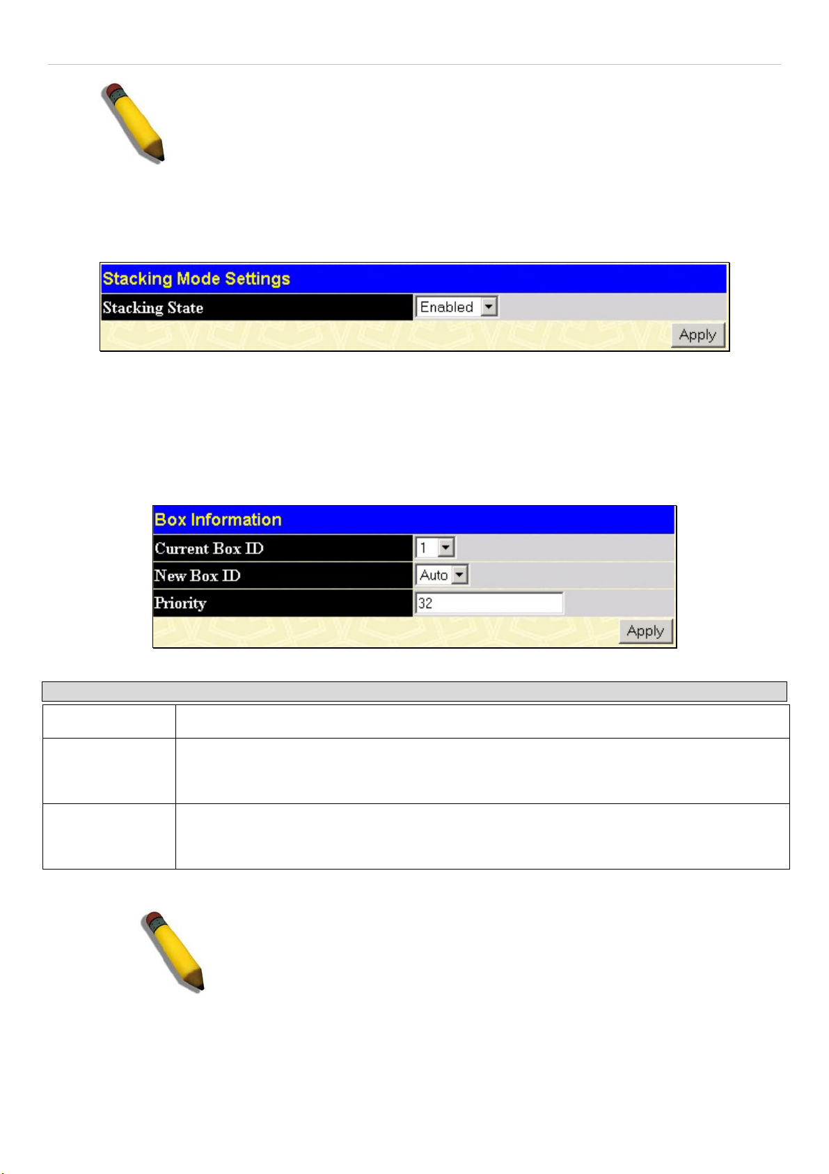
xStack DGS-3600 Series Layer 3 Gigabit Ethernet Managed Switch
NOTE: If there is a Box ID conflict when the stack is in the discovery phase, the device
will enter a special standalone topology mode. Users can only get device information,
configure Box IDs, save and reboot. All stacking ports will be disabled and an error
message will be produced on the local console port of each device in the stack. Users
must reconfigure Box IDs and reboot the stack.
Stacking Mode Settings
To begin the stacking process, users must first enable this device for stacking by using the following window. To view this
window, open the Administration folder and click Stacking > Mode Settings.
Figure 6- 4. Stacking Mode Settings window
Use the pull-down menu, choose Enabled and click Apply to allow stacking of this Switch.
Box Information
The Box Information screen is found in the Administration folder under the heading Stacking. This window is used to
configure stacking parameters associated with all switches in the xStack DGS-3600 Series. The user may configure parameters
such as box ID, box priority and pre-assigning model names to switches to be entered into the switch stack.
Figure 6- 5. Box Information Configuration window
Parameter Description
Current Box ID
New Box ID
Priority
Information configured in this screen is found in the Monitoring folder under Stack Information.
The Box ID of the switch in the stack to be configured.
The new box ID of the selected switch in the stack that was selected in the Current Box ID field.
The user may choose any number between 1 and 12 to identify the switch in the switch stack.
Auto will automatically assign a box number to the switch in the switch stack.
Displays the priority ID of the Switch. The lower the number, the higher the priority. The box
(switch) with the lowest priority number in the stack is the Primary Master switch. The Primary
Master switch will be used to configure applications of the switch stack.
NOTE: Configured box priority settings will not be implemented until users
physically save it using the Web GUI or the CLI.
IP Interface Setup
Each VLAN must be configured prior to setting up the VLAN’s corresponding IP interface.
31
Page 49

xStack DGS-3600 Series Layer 3 Gigabit Ethernet Managed Switch
An example is presented below:
VLAN Name VID Switch Ports
System (default) 1 5, 6, 7, 8, 21, 22, 23, 24
Engineer 2 9, 10, 11, 12
Marketing 3 13, 14, 15, 16
Finance 4 17, 18, 19, 20
Sales 5 1, 2, 3, 4
Backbone 6 25, 26
Table 6- 1. VLAN Example - Assigned Ports
In this case, six IP interfaces are required, so a CIDR notation of 10.32.0.0/11 (or a 11-bit) addressing scheme will work. This
addressing scheme will give a subnet mask of 11111111.11100000.00000000.00000000 (binary) or 255.224.0.0 (decimal).
Using a 10.xxx.xxx.xxx IP address notation, the above example would give six network addresses and six subnets.
Any IP address from the allowed range of IP addresses for each subnet can be chosen as an IP address for an IP interface on the
switch.
For this example, we have chosen the next IP address above the network address for the IP interface’s IP Address:
VLAN Name VID Network Number IP Address
System (default) 1 10.32.0.0 10.32.0.1
Engineer 2 10.64.0.0 10.64.0.1
Marketing 3 10.96.0.0 10.96.0.1
Finance 4 10.128.0.0 10.128.0.1
Sales 5 10.160.0.0 10.160.0.1
Backbone 6 10.192.0.0 10.192.0.1
Table 6- 2. VLAN Example - Assigned IP Interfaces
The six IP interfaces, each with an IP address (listed in the table above), and a subnet mask of 255.224.0.0 can be entered into the
Setup IP Interface window.
32
Page 50

xStack DGS-3600 Series Layer 3 Gigabit Ethernet Managed Switch
Port Configuration
This section contains information for configuring various attributes and properties for individual physical ports, including port
speed and flow control.
Port Settings
Click Administration > Port Configuration > Port Settings to display the following window:
To configure switch ports:
1. Choose the port or sequential range of ports using the From…To… port pull-down menus.
2. Use the remaining pull-down menus to configure the parameters described below:
Figure 6- 6. Port Configuration window
The following parameters can be configured:
33
Page 51

xStack DGS-3600 Series Layer 3 Gigabit Ethernet Managed Switch
Parameter Description
From…. To
State
Speed/Duplex
Flow Control
Use the pull-down menus to select the port or range of ports to be configured.
Toggle this field to either enable or disable a given port or group of ports.
Toggle the Speed/Duplex field to either select the speed and duplex/half-duplex state of the
port. Auto denotes auto-negotiation between 10 and 100 Mbps devices, in full- or half-duplex.
The Auto setting allows the port to automatically determine the fastest settings the device the
port is connected to can handle, and then to use those settings. The other options are Auto,
10M/Half, 10M/Full, 100M/Half and 100M/Full, 1000M/Full_M and 1000M/Full_S. There is no
automatic adjustment of port settings with any option other than Auto.
The Switch allows the user to configure two types of gigabit connections; 1000M/Full_M and
1000M/Full_S. Gigabit connections only support full duplex connections and take on certain
characteristics that are different from the other choices listed.
The 1000M/Full_M (master) and 1000M/Full_S (slave) parameters refer to connections running
a 1000BASE-T cable for connection between the Switch port and other device capable of a
gigabit connection. The master setting (1000M/Full_M) will allow the port to advertise capabilities
related to duplex, speed and physical layer type. The master setting will also determine the
master and slave relationship between the two connected physical layers. This relationship is
necessary for establishing the timing control between the two physical layers. The timing control
is set on a master physical layer by a local source. The slave setting (1000M/Full_S) uses loop
timing, where the timing comes form a data stream received from the master. If one connection
is set for 1000M/Full_M, the other side of the connection must be set for 1000M/Full_S. Any
other configuration will result in a link down status for both ports.
Displays the flow control scheme used for the various port configurations. Ports configured for
full-duplex use 802.3x flow control, half-duplex ports use backpressure flow control, and Auto
ports use an automatic selection of the two. The default is Disabled.
Learning
Enable or disable MAC address learning for the selected ports. When Enabled, destination and
source MAC addresses are automatically listed in the forwarding table. When learning is Dis-
abled, MAC addresses must be manually entered into the forwarding table. This is sometimes
done for security or efficiency. See the section on Forwarding/Filtering for information on
entering MAC addresses into the forwarding table. The default setting is Enabled.
Medium Type
This applies only to the Combo ports. If configuring the Combo ports this defines the type of
transport medium used. SFP ports should be set at Fiber and the Combo 1000BASE-T ports
should be set at Copper.
Click Apply to implement the new settings on the Switch.
34
Page 52

xStack DGS-3600 Series Layer 3 Gigabit Ethernet Managed Switch
Port Error Disabled
The following window will display the information about ports that have had their connection status disabled, for reasons such as
STP loopback detection or link down status. To view this window, click Port Configuration > Port Error Disabled.
Figure 6- 7. Port Error Disabled window
The following parameters are displayed:
Parameter Description
Port
Port State
Connection Status
Reason
Displays the port that has been error disabled.
Describes the current running state of the port, whether Enabled or Disabled.
This field will read the uplink status of the individual ports, whether enabled or Disabled.
Describes the reason why the port has been error-disabled, such as a STP loopback
occurrence.
35
Page 53

xStack DGS-3600 Series Layer 3 Gigabit Ethernet Managed Switch
p
t
a
f
f
d
F
Port Description
The Switch supports a port description feature where
the user may name various ports on the Switch. To
assign names to various ports, click Administration >
Port Configuration > Port Description to view the
following window:
Use the From and To
or range of ports to describe, and then enter
description of the port(s). Click Apply to set the
descriptions in the Port Description Table.
The Medium Type applies only to the Combo ports. I
configuring the Combo ports this defines the type o
transport medium used. SFP ports should be nominate
iber and the Combo 1000BASE-T ports should be
nominated Copper. The result will be displayed in the
appropriate switch port number slot (C for copper ports
and F for fiber ports).
ull down menu to choose a por
Figure 6- 8. Port Description window
36
Page 54

xStack DGS-3600 Series Layer 3 Gigabit Ethernet Managed Switch
User Accounts
Use the User Account Management window to control user privileges. To view existing User Accounts, open the
Administration folder and click on the User Accounts link. This will open the User Account Management window, as shown
below.
Figure 6- 9. User Accounts window
To add a new user, click on the Add button. To modify or delete an existing user, click on the Modify button for that user.
Figure 6- 10. User Accounts Add Table window
Add a new user by typing in a User Name, and New Password and retype the same password in the Confirm New Password.
Choose the level of privilege (Admin or User) from the Access Right drop-down menu.
Figure 6- 11. User Accounts Modify Table window
Modify or delete an existing user account in the User Account Modify Table. To delete the user account, click on the Delete
button. To change the password, type in the New Password and retype it in the Confirm New Password entry field. The level of
privilege (Admin or User) can be viewed in the Access Right field.
37
Page 55

xStack DGS-3600 Series Layer 3 Gigabit Ethernet Managed Switch
Port Mirroring
The Switch allows you to copy frames transmitted and received on a port and redirect the copies to another port. You can attach a
monitoring device to the mirrored port, such as a sniffer or an RMON probe, to view details about the packets passing through the
first port. This is useful for network monitoring and troubleshooting purposes. To view the Port Mirroring window, click Port
Mirroring in the Administration folder.
Figure 6- 12. Port Mirroring window
To configure a mirror port:
1. Select the Source Port from where you want to copy frames and the Target Port, which receives the copies from the
source port.
2. Select the Source Direction, Ingress, Egress, or Both and change the Status drop-down menu to Enabled.
3. Click Apply to let the changes take effect.
NOTE: You cannot mirror a fast port onto a slower port. For example, if you try to mirror the
traffic from a 100 Mbps port onto a 10 Mbps port, this can cause throughput problems. The port
you are copying frames from should always support an equal or lower speed than the port to
which you are sending the copies. Also, the target port for the mirroring cannot be a member of
a trunk group. Please note a target port and a source port cannot be the same port.
38
Page 56

xStack DGS-3600 Series Layer 3 Gigabit Ethernet Managed Switch
System Log Settings
The Switch can send Syslog messages to up to four designated servers using the System Log Server. In the Administration
folder, click System Log Settings, to view the window shown below.
Figure 6- 13. System Log Host window
The parameters configured for adding and editing System Log Server settings are the same. See the table below for a description.
Figure 6- 14. Configure System Log Server – Add window
The following parameters can be set:
Parameter Description
Index
Server IP
Severity
Facility
Syslog server settings index (1-4).
The IP address of the Syslog server.
This drop-down menu allows you to select the level of messages that will be sent. The options
are Warning, Informational, and All.
Some of the operating system daemons and processes have been assigned Facility values.
Processes and daemons that have not been explicitly assigned a Facility may use any of the
"local use" facilities or they may use the "user-level" Facility. Those Facilities that have been
designated are shown in the following: Bold font indicates the facility values that the Switch is
currently employing.
Numerical Facility
Code
0 kernel messages
1 user-level messages
2 mail system
3 system daemons
4 security/authorization messages
5 messages generated internally by syslog line printer subsystem
6 network news subsystem
39
Page 57
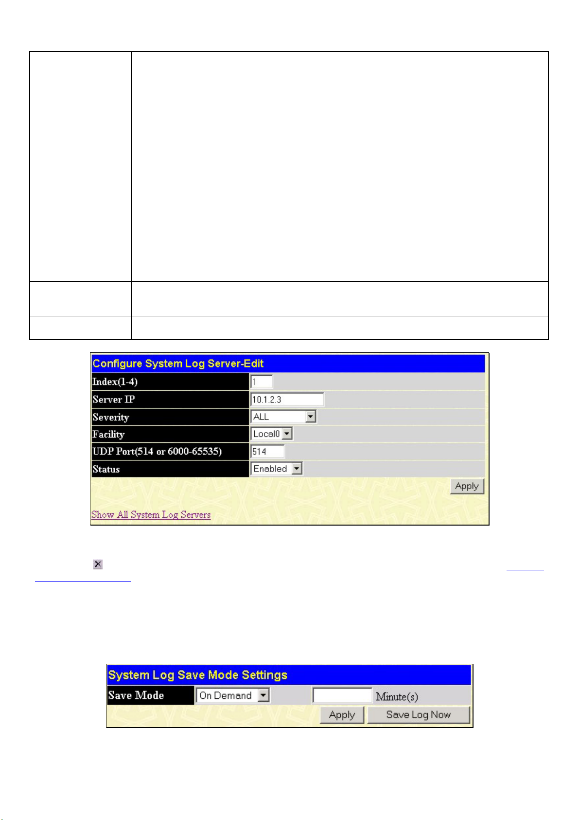
xStack DGS-3600 Series Layer 3 Gigabit Ethernet Managed Switch
UDP Port (514 or
6000-65535)
Status
7
8
9
10
11
12
13
14
15
16
17
18
19
20
21
22
Type the UDP port number used for sending Syslog messages. The default is 514.
Choose Enabled or Disabled to activate or deactivate.
UUCP subsystem
clock daemon
security/authorization messages
FTP daemon
NTP subsystem
log audit
log alert
clock daemon
local use 0 (local0)
local use 1 (local1)
local use 2 (local2)
local use 3 (local3)
local use 4 (local4)
local use 5 (local5)
local use 6 (local6)
local use 7 (local7)
Figure 6- 15. Configure System Log Server– Edit window
To set the System Log Server configuration, click Apply. To delete an entry from the System Log Host window, click the
corresponding
System Log Servers link.
under the Delete heading of the entry to delete. To return to the System Log Host window, click the Show All
System Log Save Mode Settings
The System Log Save Mode Settings window may be used to choose a method for which to save the switch log to the flash
memory of the Switch. To view this window, open the Administration folder and then click System Log > System Log Save
Mode Settings.
Figure 6- 16. System Log Save Mode Settings
Use the pull-down menu to choose the method for saving the switch log to the Flash memory. The user has three options:
40
Page 58

xStack DGS-3600 Series Layer 3 Gigabit Ethernet Managed Switch
Time Interval – Users who choose this method can configure a time interval by which the switch will save the log files, in the
box adjacent to this configuration field. The user may set a time between 1 and 65535 minutes. The default setting is one minute.
On Demand – Users who choose this method will only save log files when they manually tell the Switch to do so, using the Save
Services folder under the Save Changes link.
On Trigger – Users who choose this method will have log files saved to the Switch every time a log event occurs on the Switch.
The default setting is On Demand. Click Apply to save changes made. Click Save Log Now to immediately save log files
currently on the switch.
System Severity Settings
The Switch can be configured to allow alerts be logged or sent as a trap to an SNMP agent or both. The level at which the alert
triggers either a log entry or a trap message can be set as well. Use the System Severity Settings menu to set the criteria for alerts.
The current settings are displayed below the Settings menu. In the Administration folder, click System Severity Settings, to
view the window shown below.
Figure 6- 17. System Severity Settings window
Use the drop-down menus to configure the parameters described below.
Parameter Description
System Severity
Severity Level
Click Apply to implement the new System Severity Settings.
Choose how the alerts are used from the drop-down menu. Select log to send the alert of the
Severity Type configured to the Switch’s log for analysis. Choose trap to send it to an SNMP
agent for analysis. Select all to send the chosen alert type to an SNMP agent and the
Switch’s log for analysis.
Choose what level of alert will trigger sending the log entry or trap message as defined by the
Severity Name. Select critical to send only critical events to the Switch’s log or SNMP agent.
Choose warning to send critical and warning events to the Switch’s log or SNMP agent.
Select information to send informational, warning and critical events to the Switch’s log or
SNMP agent.
41
Page 59

xStack DGS-3600 Series Layer 3 Gigabit Ethernet Managed Switch
SNTP Settings
Time Settings
To configure the time settings for the Switch, open the Administration folder. Then the SNTP Settings folder and click on the
Time Settings link, revealing the following window for the user to configure.
Figure 6- 18. Time Settings window
The following parameters can be set or are displayed:
Parameter Description
System Boot Time
Current Time
Time Source
SNTP State
SNTP Primary Server
SNTP Secondary
Server
SNTP Poll Interval in
Seconds (30-99999)
Year
Month
Day
Time in HH MM SS
Displays the time when the Switch was initially started for this session.
Displays the Current Time set on the Switch.
Displays the time source for the system.
Use this pull-down menu to Enabled or Disabled SNTP.
This is the IP address of the primary server the SNTP information will be taken from.
This is the IP address of the secondary server the SNTP information will be taken from.
This is the interval, in seconds, between requests for updated SNTP information.
Enter the current year, if you want to update the system clock.
Enter the current month, if you would like to update the system clock.
Enter the current day, if you would like to update the system clock.
Enter the current time in hours, minutes, and seconds.
Current Time
SNTP Settings
Set Current Time
Click Apply to implement changes made.
42
Page 60

xStack DGS-3600 Series Layer 3 Gigabit Ethernet Managed Switch
Time Zone and DST
The following are windows used to configure time zones and Daylight Savings time settings for SNTP. Open the Administration
folder, then the SNTP Settings folder and click on the Time Zone and DST link, revealing the following window.
The following parameters can be set:
Parameter Description
Daylight Saving Time State
Daylight Saving Time Offset
in Minutes
Time Zone Offset from GMT
in +/- HH:MM
Use this pull-down menu to enable or disable the DST Settings.
Use this pull-down menu to specify the amount of time that will constitute your local
DST offset - 30, 60, 90, or 120 minutes.
Use these pull-down menus to specify your local time zone's offset from Greenwich
Mean Time (GMT.)
Figure 6- 19. Time Zone and DST window
Time Zone and DST
43
Page 61

xStack DGS-3600 Series Layer 3 Gigabit Ethernet Managed Switch
DST Repeating Settings
Using repeating mode will enable DST seasonal time adjustment. Repeating mode requires that the DST beginning
and ending date be specified using a formula. For example, specify to begin DST on Saturday during the second
week of April and end DST on Sunday during the last week of October.
From: Which Day
From: Day of Week
From: Month
From: Time in HH:MM
To: Which Day
To: Day of Week
To: Month
To: Time in HH:MM
Enter the week of the month that DST will start.
Enter the day of the week that DST will start on.
Enter the month DST will start on.
Enter the time of day that DST will start on.
Enter the week of the month the DST will end.
Enter the day of the week that DST will end.
Enter the month that DST will end.
Enter the time DST will end.
DST Annual Settings
Using annual mode will enable DST seasonal time adjustment. Annual mode requires that the DST beginning and
ending date be specified concisely. For example, specify to begin DST on April 3 and end DST on October 14.
From: Month
From: Day
Enter the month DST will start on, each year.
Enter the day of the week DST will start on, each year.
From: Time in HH:MM
To: Month
To: Day
To: Time in HH:MM
Enter the time of day DST will start on, each year.
Enter the month DST will end on, each year.
Enter the day of the week DST will end on, each year.
Enter the time of day that DST will end on, each year.
Click Apply to implement changes made to the Time Zone and DST window.
44
Page 62

xStack DGS-3600 Series Layer 3 Gigabit Ethernet Managed Switch
MAC Notification Settings
MAC Notification is used to monitor MAC addresses learned and entered
into the forwarding database. To globally set MAC notification on the
Switch, open the following window by opening the MAC Notification
Settings in the Administration folder.
Global Settings
The following parameters may be viewed and modified:
Parameter Description
State
Interval
(sec)
History
Size
Enable or disable MAC notification globally on the
Switch
The time in seconds between notifications.
The maximum number of entries listed in the history
log used for notification. Up to 500 entries can be
specified.
Port Settings
To change MAC notification settings for a port or group of ports on the
Switch, configure the following parameters.
Parameter Description
From…To
State
Click Apply to implement changes made.
Select a port or group of ports to enable for MAC
notification using the pull-down menus.
Enable MAC Notification for the ports selected using
the pull-down menu.
Figure 6- 20. MAC Notification Settings
45
Page 63

xStack DGS-3600 Series Layer 3 Gigabit Ethernet Managed Switch
w
TFTP Services
Trivial File Transfer Protocol (TFTP) services allo
the Switch's firmware to be upgraded by transferring
a new firmware file from a TFTP server to the
Switch. A configuration file can also be loaded into
the Switch from a TFTP server. Switch settings can
be saved to the TFTP server, and a history log can be
uploaded from the Switch to the TFTP server. The
TFTP server must be running TFTP server software
to perform the file transfer.
Figure 6- 21. TFTP Services window
The user also has the option of transferring firmware and configuration files to and from the internal Flash drive, located on the
Switch. Using this window, the user can add a configuration or firmware file from a TFTP server to the flash memory, or transfer
that firmware or configuration file to a TFTP server. More about configuring the internal Flash drive can be found in the next
section entitled Flash File Services.
TFTP server software is a part of many network management software packages – such as NetSight, or can be obtained as a
separate program. To update the Switch's firmware or configuration file, open the TFTP Services hyperlink, located in the
Administration folder.
The following parameters can be configured:
Parameter Description
Active
Server IPv4
Address
Server IPv6
Address
Select a service for the TFTP server to perform from the drop down window:
•
Download Firmware - Enter the IP address of the TFTP server and specify the
location of the new firmware on the TFTP server. Click Start to record the IP
address of the TFTP server and to initiate the file transfer.
•
Download Configuration - Enter the IP address of the TFTP server, and the path
and filename for the Configuration file on the TFTP server. Click Start to record the
IP address of the TFTP server and to initiate the file transfer.
•
Upload Configuration - Enter the IP address of the TFTP server and the path and
filename for the switch settings on the TFTP server. Click Start to record the IP
address of the TFTP server and to initiate the file transfer.
•
Upload Log - Enter the IP address of the TFTP server and the path and filename
for the history log on the TFTP server. Click Start to record the IP address of the
TFTP server and to initiate the file transfer.
•
Upload Attack Log - Enter the IP address of the TFTP server and the path and
filename for the attack log on the TFTP server. Click Start to record the IP address
of the TFTP server and to initiate the file transfer.
•
Upload Firmware - Enter the IP address of the TFTP server and the path and
filename for the place to put this firmware on the TFTP server. Click Start to record
the IP address of the TFTP server and to initiate the file transfer.
Enter the IPv4 address of the server from which to download firmware.
Enter the IPv6 address of the server from which to download firmware.
Local File Name
Enter the path and filename of the firmware or configuration file to upload or download, located
on the TFTP server.
Image File in Flash
To select a firmware file from the internal Flash drive to be transferred, or to load a firmware file
on to the Flash drive, enter the path and filename here and click the corresponding check box.
Remember, the only path that can be used on the flash is named C:/. (ex. c:/runtime.had)
Configuration File
in Flash
To select a configuration file from the internal Flash drive to be transferred, or to load a
configuration file on to the Flash drive, enter the path and filename here and click the
corresponding check box. Remember, the only path that can be used on the flash is named
C:/. (ex. c:/configuration.had)
Click Start to initiate the file transfer.
46
Page 64

xStack DGS-3600 Series Layer 3 Gigabit Ethernet Managed Switch
File System Services
The xStack DGS-3600 switch series contains a 16-megabyte Flash memory where the user may store files for further use on the
Switch. The user may place over 200 re-nameable files on the FAT 16 mode Flash memory, of which the user has the option of
setting firmware images and configuration files as boot up files, upon the next reboot of the Switch.
The Switch automatically assigns default names to the default boot up files located in the flash memory. The default firmware
files is named RUN.HAD while the default boot up configuration file is named STARTUP.CFG. After the system has powered up
or has been reset, the Switch will check the Flash memory for these files. If no corruption or other problems exist on the Flash, the
Switch will use the files set as the boot up files and load them into the Switch. If a problem occurs, the Switch will use the PROM
(programmable read-only memory) will provide the FAT 16 re-building function, which will format the Flash as FAT 16 and
enter the Z-modem download mode where the user will download firmware, saved as RUN.HAD and then boot from this
firmware image. To configure the files located on the Flash memory, use the following windows to guide you.
System Boot Information
The System Boot Info Table is used to view and configure boot up firmware images and configuration files. To set a file as a
boot up file, enter the unit ID number, file name and path into the File Name field under the Boot Image Settings heading and
click Apply. The Switch will recognize .HAD files as firmware images and .CFG files as configuration files when being set as the
boot up file. Newly configured boot up files will be displayed in the System Boot Info Table.
Figure 6- 22. System Boot Info Table window
FS Information
The FS Information window allows users to view the settings of the Flash Drive in the Switch. This information is read-only and
is just a description of the internal Flash memory.
Figure 6- 23. Media Information window
This window offers the following information about the internal Flash Drive.
Parameter Description
Unit
Drive ID
Media Type
Size
Choose the switch in the switch stack for which to view media information.
The name of the drive of the memory. There is only one drive in the Flash and it is named C:.
The type of storage media present in this Switch, which is a Flash memory system.
Denotes the size of the flash memory, which is 15 megabytes.
Label
FS Type
The label that has been factory set for this Flash memory.
The type of File System present in the Switch. For this release, only a FAT16 file system is used
in the Switch.
47
Page 65

xStack DGS-3600 Series Layer 3 Gigabit Ethernet Managed Switch
Directory
The Directory window allows users to view files stored in the flash memory of the Switch. In future releases, more than one drive
may be located in the Flash drive, but for this release, the only drive located on the Flash memory of the Switch is C:. Therefore,
to view files located on C:, the user should enter C: into the Drive ID field and click Find. Saved files will appear in the Directory
table. This window will also display the total number of files (Total Files), the amount of free bytes left (Total free size), and the
amount of memory space used for normal running of the Switch (System reserved flash size).
Figure 6- 24. Directory window
The previous window contains the following information:
Parameter Description
Drive ID
Name
Size
Date
Boot up
Delete
Enter the name of the drive located on the Flash memory. There is only one drive in the Flash
and it is named C:.
Denotes the name of the file located on the Switch’s Flash memory. The default firmware image
is called RUN.HAD, while the default configuration file is specified as STARTUP.CFG.
Denotes the size of the save file, in bytes.
Displays the date that the file was loaded onto the Switch.
An ‘*’ in this field denotes that the corresponding file is a boot up configuration file or firmware
image.
Click the
Remember, once deleted, it cannot be restored by the switch unless downloaded again from an
outside source.
in this field corresponding to the file to be deleted from the Flash memory.
Rename
The following window is used to rename files that are presently located in the Flash memory of the Switch. To rename a file,
simply choose the unit where the file is, type the path and name of the current file (ex. c:/triton) into the Old File Name field, and
then the new file and path into the New File Name field and click Apply. Remember, the path must be included in both fields,
which is c:/ on this Switch. Users may return to the Directory window to view changes made in the file names.
Figure 6- 25. Rename window
48
Page 66
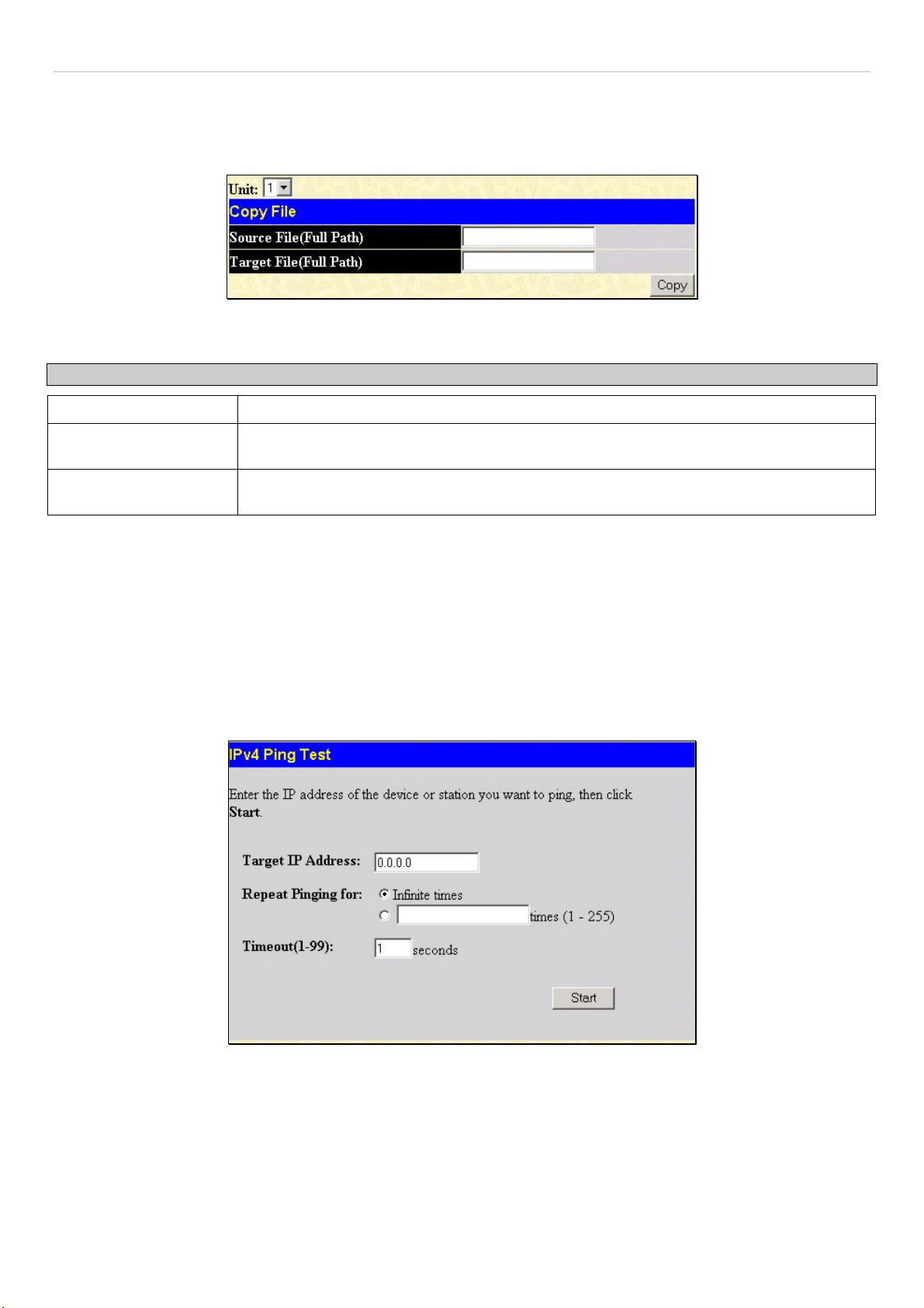
xStack DGS-3600 Series Layer 3 Gigabit Ethernet Managed Switch
Copy
This window is used to copy a directory located within the Flash memory of the switch. To view this window, click Maintenance
> CF Services > System Services > Copy. Click Copy to initiate copying the file.
Figure 6- 26. Copy File window
This window offers the following fields to aid the user in copying files located in the Flash memory of the Switch.
Parameter Description
Unit
Source File (Full Path)
Target File (Full Path)
Choose the switch in the switch stack where the file exists.
Enter the full path and file name of the directory to be copied. This entry cannot exceed 64
characters in length.
Enter the file name of the directory and the path to place the copy. This entry cannot
exceed 64 characters in length.
Ping Test
Ping is a small program that sends ICMP Echo packets to the IP address you specify. The destination node then responds to or
"echoes" the packets sent from the Switch. This is very useful to verify connectivity between the Switch and other nodes on the
network.
IPv4 Ping Test
The following window is used to Ping an IPv4 address. To locate this window, open the Administration folder and click Ping
Test > IPv4 Ping Test.
Figure 6- 27. Ping Test window
The user may use Infinite times radio button, in the Repeat Pinging for field, which will tell the ping program to keep sending
ICMP Echo packets to the specified IP address until the program is stopped. The user may opt to choose a specific number of
times to ping the Target IP Address by clicking its radio button and entering a number between 1 and 255. Click Start to initiate
the Ping program.
49
Page 67

xStack DGS-3600 Series Layer 3 Gigabit Ethernet Managed Switch
IPv6 Ping Test
The following window is used to Ping an IPv6 address. To locate this window, open the Administration folder and click Ping
Test > IPv6 Ping Test.
Figure 6- 28. IPv6 Ping Test window
This window allows the following parameters to be configured to ping an IPv6 address.
Parameter Description
IPv6 Address
Interface
Repeat Times
Size
Timeout
Click Start to initialize the Ping program.
Enter an IPv6 address to be pinged.
The Interface field is used for addresses on the link-local network. It is recommended that the
user enter the specific interface for a link-local IPv6 address. For Global IPv6 addresses, this
field may be omitted.
Enter the number of times desired to attempt to ping the IPv6 address configured in this window.
Users may enter a number of times between 0 and 255.
Use this field to set the datagram size of the packet, or in essence, the number of bytes in each
ping packet. Users may set a size between 1 and 6000 bytes with a default setting of 100 bytes.
Select a timeout period between 1 and 10 seconds for this Ping message to reach its destination.
If the packet fails to find the IPv6 address in this specified time, the Ping packet will be dropped.
50
Page 68

xStack DGS-3600 Series Layer 3 Gigabit Ethernet Managed Switch
IPv6 Neighbor
IPv6 neighbors are devices on the link-local network that have been detected as being IPv6 devices. These devices can forward
packets and keep track of the reachability of routers, as well as if changes occur within link-layer addresses of nodes on the
network or if identical unicast addresses are present on the local link. The following two windows are used to view IPv6
neighbors, and add or delete them from the Neighbor cache.
IPv6 Neighbor Settings
The following window is used to view and configure current IPv6 neighbors of the Switch. To view this window, open the
Administration folder and click IPv6 Neighbor > IPv6 Neighbor Settings.
Figure 6- 29. IPv6 Neighbor Settings window
The following fields can be viewed or configured:
Parameter Description
Interface Name
Neighbor IPv6
Address
State
Neighbor
Link Layer Address
Interface
State
To remove an entry, click the Delete button for the entry being removed. To completely clear the IPv6 Neighbor Settings, click
the Clear All button. To add a new entry, click the Add button, revealing the following screen to configure:
Enter the Interface Name of the device for which to search IPv6 neighbors. Click Find to begin
the search.
Enter the IPv6 address of the neighbor of the IPv6 device to be searched. Click Find to begin
the search.
Users may also search by running state of the IPv6 neighbor. Click the State check box and
choose to search for Static IPv6 neighbors or Dynamic IPv6 neighbors. Click Find to begin the
search.
Displays the IPv6 address of the neighbor device.
Displays the MAC Address of the corresponding IPv6 device.
Displays the Interface name associated with this IPv6 address.
Displays the running state of the corresponding IPv6 neighbor. The user may see six possible
entries in this field, which are Incomplete, Stale, Probe, Reachable, Delay or Static.
51
Page 69

xStack DGS-3600 Series Layer 3 Gigabit Ethernet Managed Switch
Figure 6- 30. IPv6 Neighbor Settings – Add window
The following fields can be set or viewed:
Parameter Description
Interface Name
Neighbor IPv6 Address
Link Layer MAC Address
After entering the IPv6 Address and MAC Address of the Static IPv6 Neighbor entry, click Apply to implement the new entry.
To return to the IPv6 Neighbor window, click the Show All IPv6 Neighbor Entries link.
Enter the name of the Interface associated with this entry, if any.
The IPv6 address of the neighbor entry. Specify the address using the hexadecimal
IPv6 Address (IPv6 Address is hexadecimal number, for example 1234::5D7F/32).
The MAC address of the IPv6 neighbor entry.
DHCP Auto Configuration Settings
This window is used to enable the DHCP Autoconfiguration feature on the Switch. When enabled, the Switch is instructed to
receive a configuration file from a TFTP server, which will set the Switch to become a DHCP client automatically on boot up. To
employ this method, the DHCP server must be set up to deliver the TFTP server IP address and configuration file name
information in the DHCP reply packet. The TFTP server must be up and running and hold the necessary configuration file stored
in its base directory when the request is received from the Switch. For more information about loading a configuration file for use
by a client, see the DHCP server and/or TFTP server software instructions. The user may also consult the Upload screen
description located in the Maintenance section of this manual.
If the Switch is unable to complete the DHCP auto configuration, the previously saved configuration file present in the Switch’s
memory will be used.
Figure 6- 31. DHCP Auto Configuration Settings window
To enable the DHCP Auto Configuration State, use the pull-down menu to choose Enabled and click the Apply button.
52
Page 70

xStack DGS-3600 Series Layer 3 Gigabit Ethernet Managed Switch
SNMP Manager
SNMP Settings
Simple Network Management Protocol (SNMP) is an OSI Layer 7 (Application Layer) designed specifically for managing and
monitoring network devices. SNMP enables network management stations to read and modify the settings of gateways, routers,
switches, and other network devices. Use SNMP to configure system features for proper operation, monitor performance and
detect potential problems in the Switch, switch group or network.
Managed devices that support SNMP include software (referred to as an agent), which runs locally on the device. A defined set of
variables (managed objects) is maintained by the SNMP agent and used to manage the device. These objects are defined in a
Management Information Base (MIB), which provides a standard presentation of the information controlled by the on-board
SNMP agent. SNMP defines both the format of the MIB specifications and the protocol used to access this information over the
network.
The xStack DGS-3600 Series supports the SNMP versions 1, 2c, and 3. The default SNMP setting is disabled. You must enable
SNMP. Once SNMP is enabled you can choose which version you want to use to monitor and control the Switch. The three
versions of SNMP vary in the level of security provided between the management station and the network device.
In SNMP v.1 and v.2, user authentication is accomplished using 'community strings', which function like passwords. The remote
user SNMP application and the Switch SNMP must use the same community string. SNMP packets from any station that has not
been authenticated are ignored (dropped).
The default community strings for the Switch used for SNMP v.1 and v.2 management access are:
• public - Allows authorized management stations to retrieve MIB objects.
• private - Allows authorized management stations to retrieve and modify MIB objects.
SNMPv3 uses a more sophisticated authentication process that is separated into two parts. The first part is to maintain a list of
users and their attributes that are allowed to act as SNMP managers. The second part describes what each user on that list can do
as an SNMP manager.
The Switch allows groups of users to be listed and configured with a shared set of privileges. The SNMP version may also be set
for a listed group of SNMP managers. Thus, you may create a group of SNMP managers that are allowed to view read-only
information or receive traps using SNMPv1 while assigning a higher level of security to another group, granting read/write privileges using SNMPv3.
Using SNMPv3 individual users or groups of SNMP managers can be allowed to perform or be restricted from performing
specific SNMP management functions. The functions allowed or restricted are defined using the Object Identifier (OID)
associated with a specific MIB. An additional layer of security is available for SNMPv3 in that SNMP messages may be
encrypted. To read more about how to configure SNMPv3 settings for the Switch read the next section.
Traps
Traps are messages that alert network personnel of events that occur on the Switch. The events can be as serious as a reboot
(someone accidentally turned OFF the Switch), or less serious like a port status change. The Switch generates traps and sends
them to the trap recipient (or network manager). Typical traps include trap messages for Authentication Failure, Topology Change
and Broadcast\Multicast Storm.
MIBs
The Switch in the Management Information Base (MIB) stores management and counter information. The Switch uses the
standard MIB-II Management Information Base module. Consequently, values for MIB objects can be retrieved from any SNMPbased network management software. In addition to the standard MIB-II, the Switch also supports its own proprietary enterprise
MIB as an extended Management Information Base. Specifying the MIB Object Identifier may also retrieve the proprietary MIB.
MIB values can be either read-only or read-write.
The xStack DGS-3600 Series incorporates a flexible SNMP management for the switching environment. SNMP management can
be customized to suit the needs of the networks and the preferences of the network administrator. Use the SNMP V3 menus to
select the SNMP version used for specific tasks.
The xStack DGS-3600 Series supports the Simple Network Management Protocol (SNMP) versions 1, 2c, and 3. The
administrator can specify the SNMP version used to monitor and control the Switch. The three versions of SNMP vary in the level
of security provided between the management station and the network device.
SNMP settings are configured using the menus located on the SNMP V3 folder of the web manager. Workstations on the network
that are allowed SNMP privileged access to the Switch can be restricted with the Management Station IP Address menu.
53
Page 71

xStack DGS-3600 Series Layer 3 Gigabit Ethernet Managed Switch
SNMP Traps Settings
The following window is used to enable and disable trap settings for the SNMP function on the Switch. To view this window for
configuration, click Administration > SNMP Manager > SNMP Trap Settings:
Figure 6- 32. SNMP Trap Settings window
To enable or disable the Traps State and/or the Authenticate Traps State, use the corresponding pull-down menu to change and
click Apply.
SNMP User Table
The SNMP User Table displays all of the SNMP User's currently configured on the Switch.
In the SNMP Manager folder, located in the Administration folder, click on the SNMP User Table link. This will open the
SNMP User Table window, as shown below.
Figure 6- 33. SNMP User Table window
To delete an existing SNMP User Table entry, click the
delete.
To display the detailed entry for a given user, click on the View button under the Display heading. This will open the SNMP User
Table Display window, as shown below.
Figure 6- 34. SNMP User Table Display window
The following parameters are displayed:
Parameter Description
User Name
An alphanumeric string of up to 32 characters. This is used to identify the SNMP users.
below the Delete heading corresponding to the entry you wish to
Group Name
SNMP Version
This name is used to specify the SNMP group created can request SNMP messages.
V1 - Indicates that SNMP version 1 is in use.
V2 - Indicates that SNMP version 2 is in use.
V3 - Indicates that SNMP version 3 is in use.
54
Page 72

xStack DGS-3600 Series Layer 3 Gigabit Ethernet Managed Switch
Auth-Protocol
None - Indicates that no authorization protocol is in use.
MD5 - Indicates that the HMAC-MD5-96 authentication level will be used.
SHA - Indicates that the HMAC-SHA authentication protocol will be used.
Priv-Protocol
None - Indicates that no authorization protocol is in use.
DES - Indicates that DES 56-bit encryption is in use based on the CBC-DES (DES-56)
standard.
To return to the SNMP User Table, click the Show All SNMP User Table Entries link. To add a new entry to the SNMP User
Table Configuration window, click on the Add button on the SNMP User Table window. This will open the SNMP User Table
Configuration window, as shown below.
Figure 6- 35. SNMP User Table Configuration window
The following parameters can set:
Parameter Description
User Name
Group Name
SNMP Version
Enter an alphanumeric string of up to 32 characters. This is used to identify the SNMP user.
This name is used to specify the SNMP group created can request SNMP messages.
V1 - Specifies that SNMP version 1 will be used.
V2 - Specifies that SNMP version 2 will be used.
V3 - Specifies that SNMP version 3 will be used.
Auth-Protocol
MD5 - Specifies that the HMAC-MD5-96 authentication level will be used. This field is only
operable when V3 is selected in the SNMP Version field and the Encryption field has been
checked. This field will require the user to enter a password.
SHA - Specifies that the HMAC-SHA authentication protocol will be used. This field is only
operable when V3 is selected in the SNMP Version field and the Encryption field has been
checked. This field will require the user to enter a password.
Priv-Protocol
None - Specifies that no authorization protocol is in use.
DES - Specifies that DES 56-bit encryption is in use, based on the CBC-DES (DES-56)
standard. This field is only operable when V3 is selected in the SNMP Version field and the
Encryption field has been checked. This field will require the user to enter a password
between 8 and 16 alphanumeric characters.
Encrypted
Checking the corresponding box will enable encryption for SNMP V3 and is only operable in
SNMP V3 mode.
To implement changes made, click Apply. To return to the SNMP User Table, click the Show All SNMP User Table Entries link.
55
Page 73
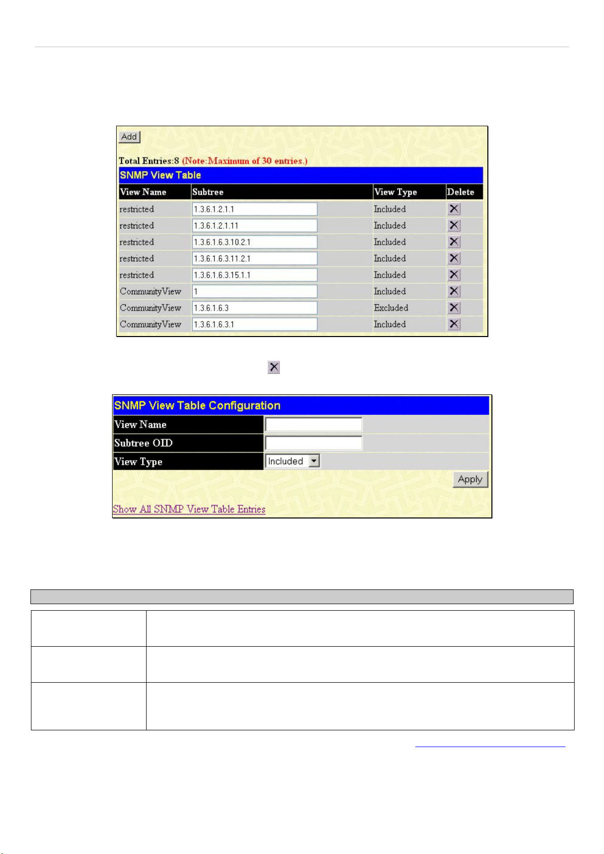
xStack DGS-3600 Series Layer 3 Gigabit Ethernet Managed Switch
SNMP View Table
The SNMP View Table is used to assign views to community strings that define which MIB objects can be accessed by a remote
SNMP manager. To view the SNMP View Table window, open the SNMP Manager folder under Administration and click the
SNMP View Table entry. The following window should appear:
Figure 6- 36. SNMP View Table window
To delete an existing SNMP View Table entry, click the
new entry, click the Add button and a separate window will appear.
Figure 6- 37. SNMP View Table Configuration window
The SNMP Group created with this table maps SNMP users (identified in the SNMP User Table) to the views created in the
previous window.
The following parameters can set:
Parameter Description
View Name
Subtree OID
Type an alphanumeric string of up to 32 characters. This is used to identify the new SNMP
view being created.
Type the Object Identifier (OID) Subtree for the view. The OID identifies an object tree (MIB
tree) that will be included or excluded from access by an SNMP manager.
in the Delete column corresponding to the entry to delete. To create a
View Type
To implement your new settings, click Apply. To return to the SNMP View Table, click the Show All SNMP View Table Entries
link.
Select Included to include this object in the list of objects that an SNMP manager can
access. Select Excluded to exclude this object from the list of objects that an SNMP
manager can access.
56
Page 74

xStack DGS-3600 Series Layer 3 Gigabit Ethernet Managed Switch
SNMP Group Table
An SNMP Group created with this table maps SNMP users (identified in the SNMP User Table) to the views created in the
previous menu. To view the SNMP Group Table window, open the SNMP Manager folder in the Administration folder and
click the SNMP Group Table entry. The following window should appear:
Figure 6- 38. SNMP Group Table window
To delete an existing SNMP Group Table entry, click the corresponding
To display the current settings for an existing SNMP Group Table entry, click the View button located under the Display
heading, which will show the following window.
Figure 6- 39. SNMP Group Table Display window
To add a new entry to the Switch's SNMP Group Table, click the Add button in the upper left-hand corner of the SNMP Group
Table window. This will open the SNMP Group Table Configuration window, as shown below.
under the Delete heading.
Figure 6- 40. SNMP Group Table Configuration window
57
Page 75

xStack DGS-3600 Series Layer 3 Gigabit Ethernet Managed Switch
The following parameters can set:
Parameter Description
Group Name Type an alphanumeric string of up to 32 characters. This is used to identify the new SNMP
group of SNMP users.
Read View Name
This name is used to specify the SNMP group created can request SNMP messages.
Write View Name Specify a SNMP group name for users that are allowed SNMP write privileges to the Switch's
SNMP agent.
Notify View Name Specify a SNMP group name for users that can receive SNMP trap messages generated by
the Switch's SNMP agent.
Security Model
SNMPv1 - Specifies that SNMP version 1 will be used.
SNMPv2 - Specifies that SNMP version 2c will be used. The SNMPv2 supports both
centralized and distributed network management strategies. It includes improvements in the
Structure of Management Information (SMI) and adds some security features.
SNMPv3 - Specifies that the SNMP version 3 will be used. SNMPv3 provides secure access
to devices through a combination of authentication and encrypting packets over the network.
Security Level
The Security Level settings only apply to SNMPv3.
NoAuthNoPriv - Specifies that there will be no authorization and no encryption of packets sent
between the Switch and a remote SNMP manager.
AuthNoPriv - Specifies that authorization will be required, but there will be no encryption of
packets sent between the Switch and a remote SNMP manager.
AuthPriv - Specifies that authorization will be required, and that packets sent between the
Switch and a remote SNMP manger will be encrypted.
To implement your new settings, click Apply. To return to the SNMP Group Table, click the Show All SNMP Group Table
Entries link.
SNMP Community Table Configuration
Use this table to create an SNMP community string to define the relationship between the SNMP manager and an agent. The
community string acts like a password to permit access to the agent on the Switch. One or more of the following characteristics
can be associated with the community string:
An Access List of IP addresses of SNMP managers that are permitted to use the community string to gain access to
•
the Switch's SNMP agent.
•
Any MIB view that defines the subset of all MIB objects will be accessible to the SNMP community.
•
Read/write or read-only level permission for the MIB objects accessible to the SNMP community.
To configure SNMP Community entries, open the SNMP Manager folder, (located in the Administration folder) and click the
SNMP Community Table link, which will open the following window:
Figure 6- 41. SNMP Community Table Configuration window
The following parameters can set:
58
Page 76
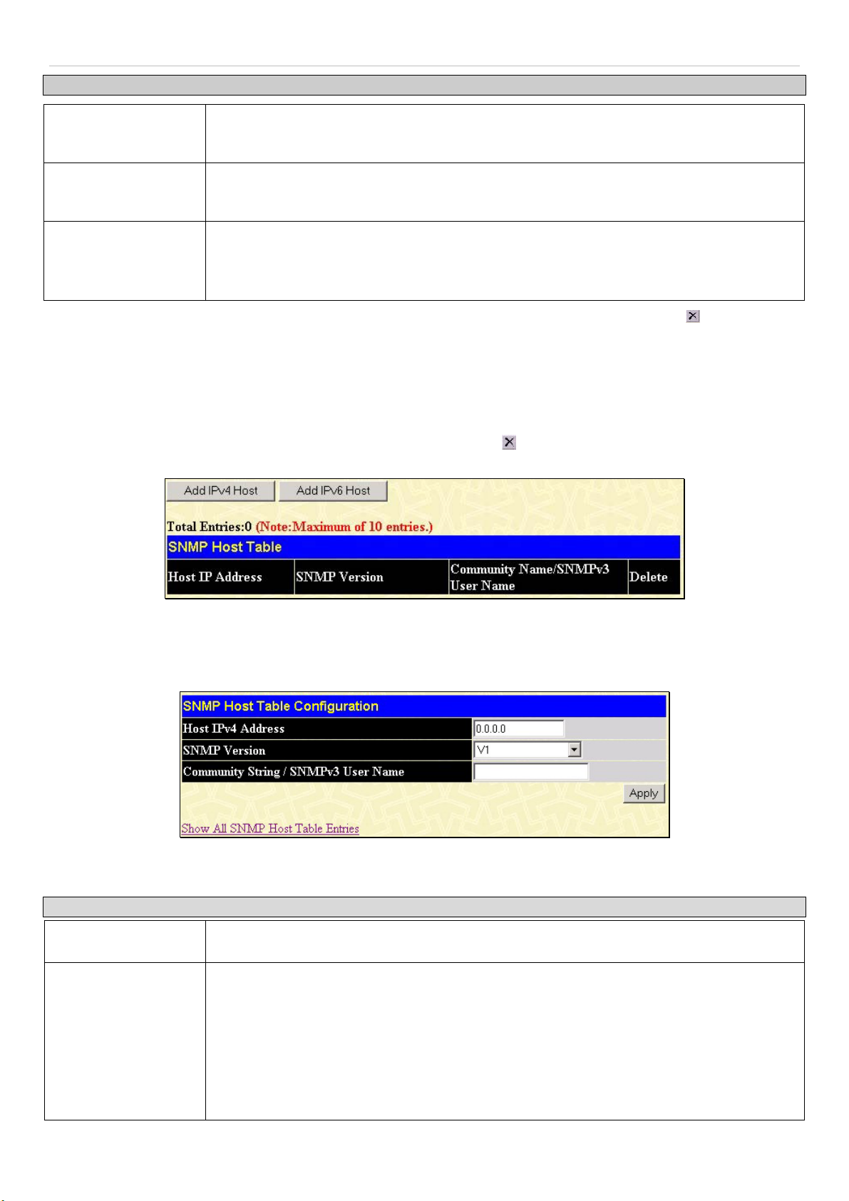
xStack DGS-3600 Series Layer 3 Gigabit Ethernet Managed Switch
Parameter Description
Community Name
View Name
Access Right
To implement the new settings, click Apply. To delete an entry from the SNMP Community Table, click the under the Delete
heading, corresponding to the entry to delete.
Type an alphanumeric string of up to 32 characters that is used to identify members of an
SNMP community. This string is used like a password to give remote SNMP managers
access to MIB objects in the Switch's SNMP agent.
Type an alphanumeric string of up to 32 characters that is used to identify the group of MIB
objects that a remote SNMP manager is allowed to access on the Switch. The view name
must exist in the SNMP View Table.
Read Only - Specifies that SNMP community members using the community string created
can only read the contents of the MIBs on the Switch.
Read Write - Specifies that SNMP community members using the community string created
can read from, and write to the contents of the MIBs on the Switch.
SNMP Host Table
Use the SNMP Host Table window to set up SNMP trap recipients. Open the SNMP Manager folder, (located in the
Administration folder) and click on the SNMP Host Table link. This will open the SNMP Host Table window, as shown
below. To delete an existing SNMP Host Table entry, click the corresponding
settings for an existing SNMP Group Table entry, click the blue link for the entry under the Host IP Address heading.
under the Delete heading. To display the current
Figure 6- 42. SNMP Host Table window
Users now have the choice of adding an IPv4 or an IPv6 host to the SNMP host table. To add a new IPv4 entry to the Switch's
SNMP Host Table, click the Add IPv4 Host button in the upper left-hand corner of the window. This will open the SNMP Host
Table Configuration window, as shown below.
Figure 6- 43. SNMP IPv4 Host Table Configuration window
The following parameters can set:
Parameter Description
Host IPv4 Address
SNMP Version
Type the IPv4 address of the remote management station that will serve as the SNMP host
for the Switch.
V1 - To specifies that SNMP version 1 will be used.
V2 - To specify that SNMP version 2 will be used.
V3-NoAuth-NoPriv - To specify that the SNMP version 3 will be used, with a NoAuth-NoPriv
security level.
V3-Auth-NoPriv - To specify that the SNMP version 3 will be used, with an Auth-NoPriv
security level.
V3-Auth-Priv - To specify that the SNMP version 3 will be used, with an Auth-Priv security
level.
59
Page 77
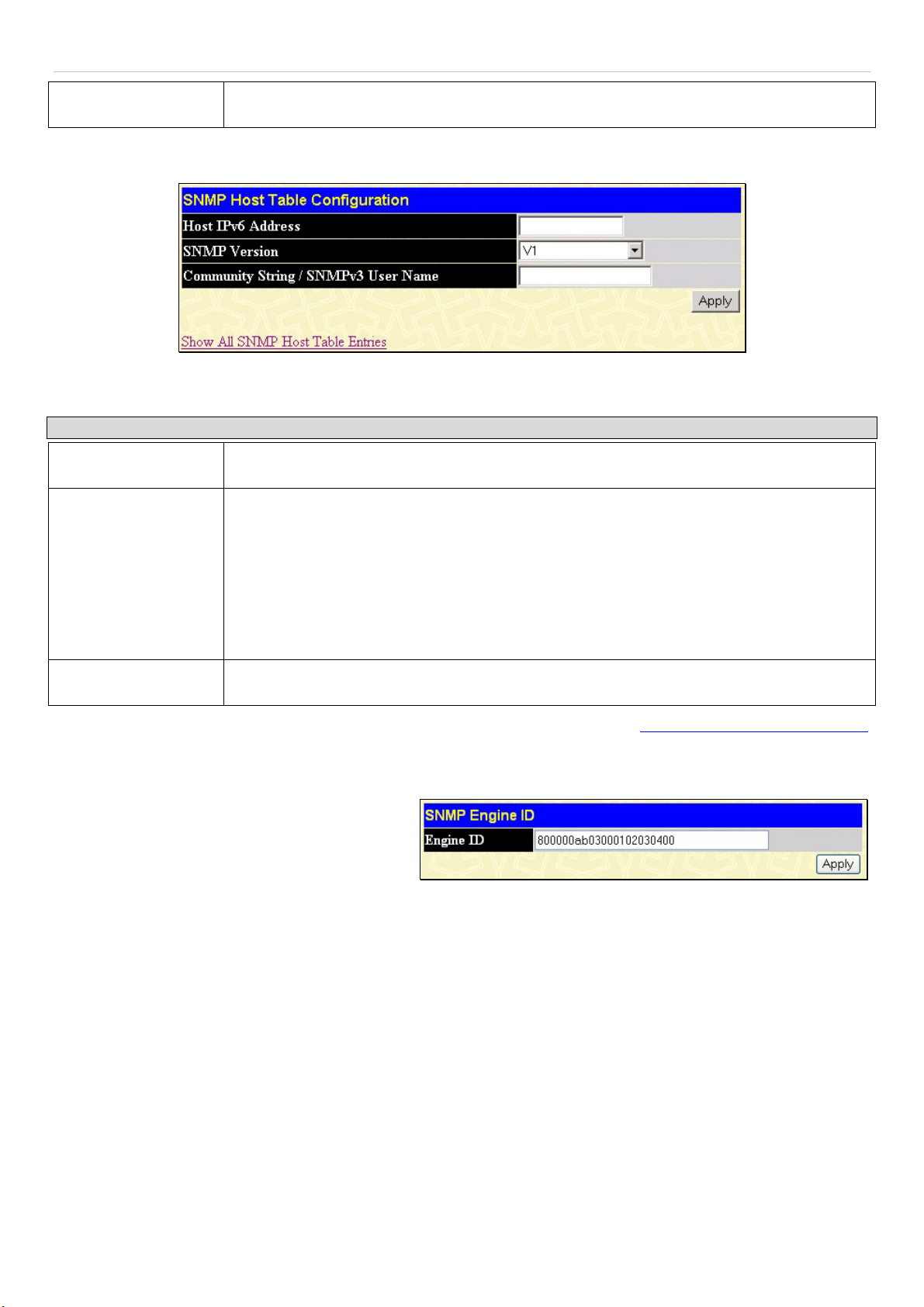
xStack DGS-3600 Series Layer 3 Gigabit Ethernet Managed Switch
ger
k
n
Community String or
SNMP V3 User Name
To add a new IPv6 entry to the Switch's SNMP Host Table, click the Add IPv6 Host button in the upper left-hand corner of the
window. This will open the SNMP Host Table Configuration window, as shown below.
The following parameters can set:
Parameter Description
Host IPv6 Address
SNMP Version
Type in the community string or SNMP V3 user name as appropriate.
Figure 6- 44. SNMP IPv6 Host Table Configuration window
Type the IPv6 address of the remote management station that will serve as the SNMP host
for the Switch.
V1 - To specifies that SNMP version 1 will be used.
V2 - To specify that SNMP version 2 will be used.
V3-NoAuth-NoPriv - To specify that the SNMP version 3 will be used, with a NoAuth-NoPriv
security level.
V3-Auth-NoPriv - To specify that the SNMP version 3 will be used, with an Auth-NoPriv
security level.
V3-Auth-Priv - To specify that the SNMP version 3 will be used, with an Auth-Priv security
level.
Community String or
SNMP V3 User Name
To implement your new settings, click Apply. To return to the SNMP Host Table, click the Show All SNMP Host Table Entries
link.
Type in the community string or SNMP V3 user name as appropriate.
SNMP Engine ID
The Engine ID is a unique identifier used for SNMP V3
implementations. This is an alphanumeric string used to
identify the SNMP engine on the Switch. To display the
Switch's SNMP Engine ID, open the SNMP Man
folder, (located in the Administration) folder and clic
on the SNMP Engine ID link. This will open the
SNMP Engine ID Configuration window, as show
below.
To change the Engine ID, type the new Engine ID in the space provided and click the Apply button.
Figure 6- 45. SNMP Engine ID window
60
Page 78

xStack DGS-3600 Series Layer 3 Gigabit Ethernet Managed Switch
d
d
d
IP-MAC-Port Binding
The IP network layer uses a four-byte address. The Ethernet link layer uses a six-byte MAC address. Binding these two address
types together allows the transmission of data between the layers. The primary purpose of IP-MAC binding is to restrict the access
to a switch to a number of authorized users. Only the authorized client can access the Switch’s port by checking the pair of IPMAC addresses with the pre-configured database. If an unauthorized user tries to access an IP-MAC binding enabled port, the
system will block the access by dropping its packet. The maximum number of IP-MAC binding entries is dependant on chip
capability (e.g. the ARP table size) and storage size of the device. For the xStack DGS-3600 Series switches, the maximum
number of IP-MAC Binding entries is 500. The creation of authorized users can be manually configured by CLI or Web. The
function is port-based, meaning a user can enable or disable the function on the individual port.
ACL Mode
Due to some special cases that have arisen with the
IP-MAC binding, this Switch has been equippe
with a special ACL Mode for IP-MAC Binding,
which should alleviate this problem for users. When
enabled in the IP-MAC Binding Port window, the
Switch will create two entries in the Access Profile
Table as shown below. The entries may only be
created if there are at least two Access Profile IDs
available on the Switch. If not, when the ACL
Mode is enabled, an error message will be prompte
to the user. When the ACL Mode is enabled, the
Switch will only accept IP packets from a create
entry in the IP-MAC Binding Setting window. All
others will be discarded.
To view the particular configurations associated with these two entries, click their corresponding View button, which will display
the following:
Figure 6- 46. Access Profile Table window
Figure 6- 47. Access Profile Entry Display windows for IP-MAC ACL Mode Enabled Entries
These two entries cannot be modified or deleted using the Access Profile Table. The user may only remove these two entries by
disabling the ACL Mode in the IP-MAC Binding Port window.
Also, rules will be created for every port on the Switch. To view the ACL rule configurations set for the ACL mode, click the
corresponding modify button of the entry in the Access Profile Table, which will produce a window similar to the example to the
right. The user may view the configurations on a port-by-port basis by clicking the View button under the Display heading of the
corresponding port entry. These entries cannot be modified or deleted, and new rules cannot be added. Yet, these windows will
offer vital information to the user when configuring other access profile entries.
Figure 6- 48. Access Rule Table windows for IP-MAC Binding rule
61
Page 79
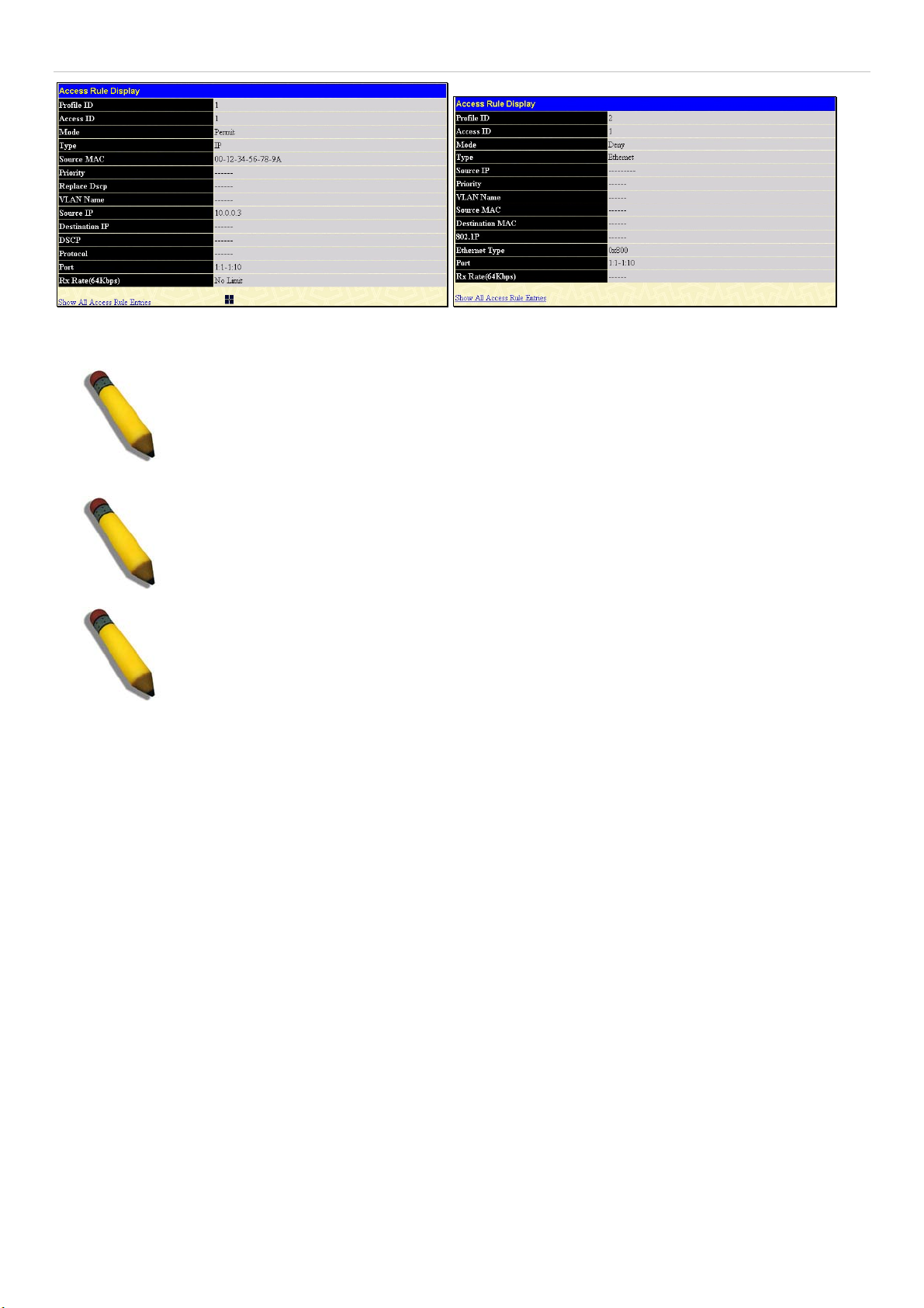
xStack DGS-3600 Series Layer 3 Gigabit Ethernet Managed Switch
Figure 6- 49. Access Rule Display windows for IP MAC Binding
NOTE: When configuring the ACL mode function of the IP-MAC binding function, please pay
close attention to previously set ACL entries. Since the ACL mode entries will fill the first two
available access profiles and access profile IDs denote the ACL priority, the ACL mode entries
may take precedence over other configured ACL entries. This may render some user-defined
ACL parameters inoperable due to the overlapping of settings combined with the ACL entry
priority (defined by profile ID). For more information on ACL settings, please see “Configuring
the Access Profile” section mentioned previously in this chapter.
NOTE: Once ACL profiles have been created by the Switch through the IP-MAC binding
function, the user cannot modify, delete or add ACL rules to these ACL mode access profile
entries. Any attempt to modify, delete or add ACL rules will result in a configuration error as
seen in the previous figure.
NOTE: When uploading configuration files to the Switch, be aware of the ACL configurations
loaded, as compared to the ACL mode access profile entries set by this function, which may
cause both access profile types to experience problems.
62
Page 80

xStack DGS-3600 Series Layer 3 Gigabit Ethernet Managed Switch
k
IP-MAC Binding Port
To enable or disable IP-MAC binding on specific ports, clic
IP-MAC Binding Port in the IP-MAC Binding folder on the
Administration Menu to open the IP-MAC Binding Ports
Setting window. Select a port or a range of ports with the
From and To fields. Enable or disable the port with the State
field. The user may also enable the ACL Mode for IP-MAC
Binding which will create two Access Profile Entries on the
Switch, as previously stated. Click Apply to save changes.
Figure 6- 50. IP-MAC Binding Ports Setting window
63
Page 81
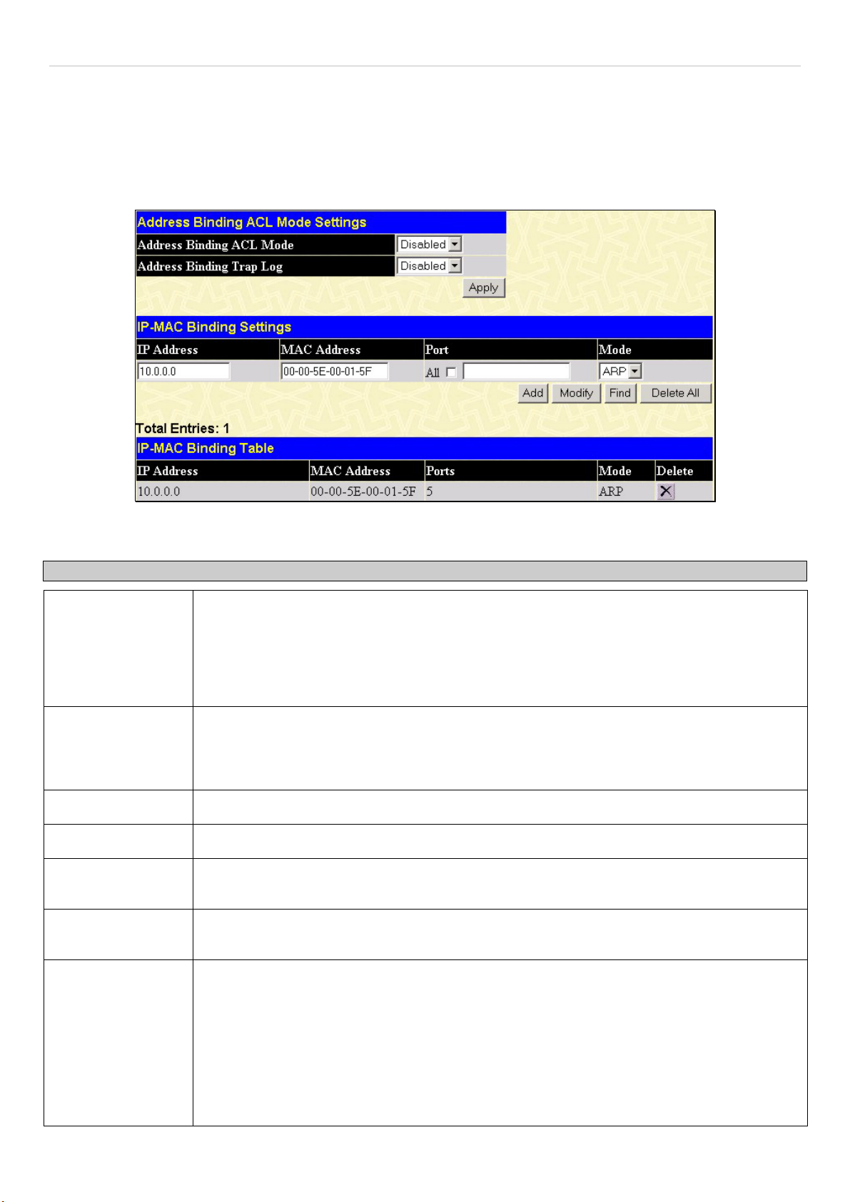
xStack DGS-3600 Series Layer 3 Gigabit Ethernet Managed Switch
IP-MAC Binding Table
The window shown below can be used to create IP-MAC binding entries. Click the IP-MAC Binding Table on the IP-MAC
Binding folder on the Administration menu to view the IP-MAC Binding Setting window. Enter the IP and MAC addresses of
the authorized users in the appropriate fields and click Add. To modify either the IP address or the MAC address of the binding
entry, make the desired changes in the appropriate field and Click Modify. To find an IP-MAC binding entry, enter the IP and
MAC addresses and click Find. To delete an entry click Delete. To clear all the entries from the table click Delete All.
Figure 6- 51. Address Binding ACL Mode Settings window
The following fields can be set or modified:
Parameter Description
Address Binding
ACL Mode
ACL Binding Trap
Log
IP Address
MAC Address
All Ports
This field will enable and disable the ACL mode for IP-MAC binding on the Switch, without
altering previously set configurations. When enabled, the Switch will automatically create two
ACL packet content mask entries that will aid the user in processing certain IP-MAC binding
entries created. The ACL entries created when this command is enabled, can only be
automatically installed if the Access Profile table has two entries available of the possible 14
entries allowed.
This field will enable and disable the sending of trap log messages for IP-MAC binding. When
enabled, the Switch will send a trap log message to the SNMP agent and the Switch log when
an ARP packet is received that doesn’t match the IP-MAC binding configuration set on the
Switch.
Enter the IP address you wish to bind to the MAC address set below.
Enter the MAC address you wish to bind to the IP Address set above.
Click this check box to configure this IP-MAC binding entry (IP Address + MAC Address) for all
ports on the Switch.
Ports
Mode
Specify the switch ports for which to configure this IP-MAC binding entry (IP Address + MAC
Address). Click the All check box to configure this entry for all ports on the Switch.
The user may set the IP-MAC Binding Mode here by using the pull-down menu. The choices
are:
ARP – Choosing this selection will set a normal IP-Mac Binding entry for the IP address and
MAC address entered.
ACL – Choosing this entry will allow only packets from the source IP-MAC binding entry
created here. All other packets with a different IP address will be discarded by the Switch. This
mode can only be used if the ACL Mode has been enabled in the IP-MAC Binding Ports
window as seen previously.
64
Page 82
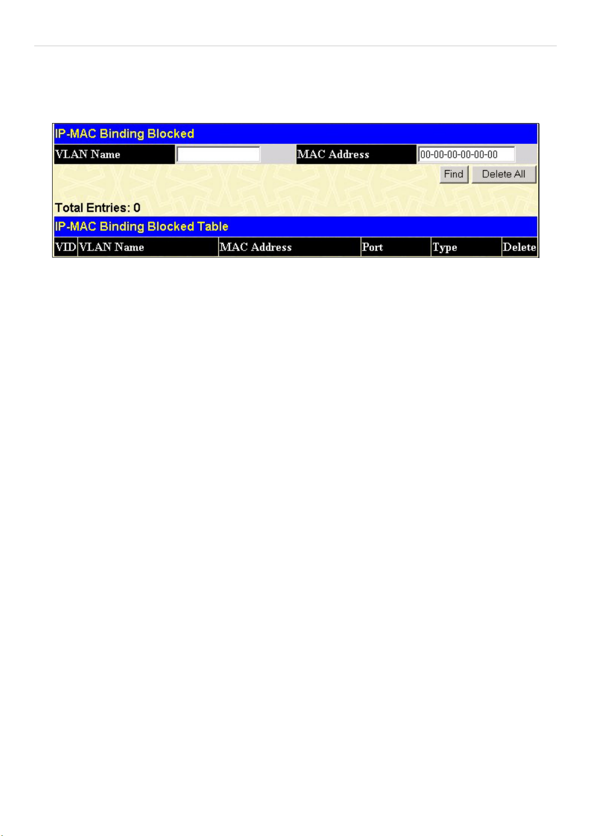
xStack DGS-3600 Series Layer 3 Gigabit Ethernet Managed Switch
IP-MAC Binding Blocked
To view unauthorized devices that have been blocked by IP-MAC binding restrictions open the IP-MAC Binding Blocked
window show below. Click IP-MAC Binding Blocked in the IP-MAC Blocked folder on the Configuration menu to open the
IP-MAC Binding Blocked window.
Figure 6- 52. IP-MAC Binding Blocked window
To find an unauthorized device that has been blocked by the IP-MAC binding restrictions, enter the VLAN name and MAC
Address in the appropriate fields and click Find. To delete an entry click the delete button next to the entry’s MAC address. To
delete all the entries in the IP-MAC Binding Blocked Table click Delete All.
65
Page 83

xStack DGS-3600 Series Layer 3 Gigabit Ethernet Managed Switch
r
t
d
t
d
t
a
p
t
w
r
f
sFlow
sFlow is a feature for the xStack DGS-3600 Series
that allows users to monitor network traffic running
through the switch to identify network problems
through packet sampling and packet counte
information of the Switch. The Switch itself is the
sFlow agent where packet data is retrieved and sen
to an sFlow Analyzer where it can be scrutinized an
utilized to resolve the problem.
The Switch can configure the settings for the sFlow
Analyzer but the remote sFlow Analyzer device mus
have an sFlow utility running on it to retrieve an
analyze the data it receives from the sFlow agent.
The Switch itself will collect three types of packe
data:
1. It will take sample packets from the normal
running traffic of the Switch based on
sampling interval configured by the user.
2. The Switch will take a poll of the IF
counters located on the switch.
3. The Switch will also take a part of the
acket header. The length of the packe
header can also be determined by the user.
Once this information has been gathered by the
switch, it is packaged into a packet called an sFlo
datagram, which is then sent to the sFlow Analyze
for analysis.
For a better understanding of the sFlow feature o
this Switch, refer to the adjacent diagram.
Figure 6- 53. sFlow Basic Setup
sFlow Global Settings
The following window is used to globally enable the sFlow feature for the Switch. Simply use the pull-down menu and click
Apply to enable or disable sFlow. This window will also display the sFlow version currently being utilized by the Switch, along
with the sFlow Address which is the Switch’s IP address.
Figure 6- 54. sFlow Global Settings window
66
Page 84

xStack DGS-3600 Series Layer 3 Gigabit Ethernet Managed Switch
sFlow Analyzer Settings
The following windows are used to configure the parameters for the remote sFlow Analyzer (collector) that will be used to gather
and analyze sFlow Datagrams that originate from the Switch. Users must have the proper sFlow software set on the Analyzer in
order to receive datagrams from the switch to be analyzed, and to analyze these datagrams. Users may specify up to four unique
analyzers to receive datagrams, yet the virtual port used must be unique to each entry.
To configure the settings for the sFlow analyzer, click the Administration link, open the sFlow folder and click sFlow Analyzer
Settings, which will produce the following window, displaying the parameters for the sFlow Analyzer.
Figure 6- 55. sFlow Analyzer Settings window
The following fields are displayed:
Parameter Description
Server ID
Owner
Timeout
Countdown Time
Address
Port
Max Datagram Size
Modify
This field denotes the ID of the Analyzer Server that has been added to the sFlow settings. Up
to four entries can be added, but each entry must have its own unique UDP Port.
Displays the owner of the entry made here. The user that added this sFlow analyzer
configured this name.
Displays the configured time, in seconds, after which the Analyzer server will time out. When
the server times out, all sFlow samples and counter polls associated with this server will be
deleted.
Displays the current time remaining before this Analyzer server times out. When the server
times out, all sFlow samples and counter polls associated with this server will be deleted.
Displays the IP address of the sFlow Analyzer Server. This IP address is where sFlow
datagrams will be sent for analysis.
Displays the previously configured UDP port where sFlow datagrams will be sent for analysis.
Only one Analyzer Address can be set for one UDP Analyzer Port.
This field displays the maximum number of data bytes in a single sFlow datagram that will be
sent to this sFlow Analyzer Server.
Click the Modify button to display the sFlow Counter Analyzer Edit window, so that users
may edit the settings for this server.
Delete
To add a new sFlow Analyzer, click the Add button in the previous window that will display the following window to be
configured:
Click the
of the corresponding entry to be deleted.
67
Page 85

xStack DGS-3600 Series Layer 3 Gigabit Ethernet Managed Switch
Figure 6- 56. sFlow Counter Analyzer – Add window
The following fields can be set or modified:
Parameter Description
Analyzer Server
Enter an integer from 1 to 4 to denote the sFlow Analyzer to be added. Up to four entries can
be added, but each entry must have its own unique Collector Port.
Owner
Users may enter an alphanumeric string of up to 16 characters to define the owner of this
entry. Users are encouraged to give this field a name that will help them identify this entry.
When an entry is made in this field, the following Timeout field is automatically set to 400
seconds, unless the user alters the Timeout field.
Timeout
This field is used to specify the timeout for the Analyzer server. When the server times out, all
sFlow samples and counter polls associated with this server will be deleted. The user may set
a time between 1 and 2000000 seconds with a default setting of 400 seconds.
Collector Address
The IP address of the sFlow Analyzer Server. If this field is not specified, the entry will become
0.0.0.0 and therefore the entry will be inactive. Users must set this field.
Collector Port
The destination UDP port where sFlow datagrams will be sent. The default setting for this field
is 6343. Only one Analyzer Server address can be set for one UDP Collector Port.
Max Datagram Size
This field will specify the maximum number of data bytes that can be packaged into a single
sFlow datagram. Users may select a value between 300 and 1400 bytes with a default setting
of 1400 bytes.
Click Apply to save changes made.
To edit an entry that has already been configured, click the Modify button of an entry in the sFlow Analyzer Settings window
which will produce the following window for the user to configure. This window holds the same information as the previous Add
window and therefore, the previous descriptions of the parameters remain valid here. Click Apply to save changes made to this
window.
Figure 6- 57. sFlow Counter Analyzer – Edit window
68
Page 86

xStack DGS-3600 Series Layer 3 Gigabit Ethernet Managed Switch
sFlow Sampler Settings
The sFlow Sampler Settings window will allow users to configure the Switch’s settings for taking sample packets from the
network, including the sampling rate and the amount of the packet header to be extracted. To configure the settings for the sFlow
Sampler, click the Administration link, open the sFlow folder and click sFlow Sampler Settings, which will produce the
following window, displaying the parameters for the sFlow Sampler.
Figure 6- 58. sFlow Sampler Settings window
The following fields are displayed:
Parameter Description
Port
Analyzer Server ID
Configured rate
Active Rate
Max Header Size
Modify
Delete
To add a new sFlow Sampler setting, click the Add button in the previous window which will display the following window to be
configured:
Displays the port from which packet samples are being extracted.
Displays the ID of the Analyzer Server where datagrams, containing the packet sampling
information taken using this sampling mechanism, will be sent.
Displays the configured rate of packet sampling for this port based on a multiple of 256. For
example, if a figure of 20 is in this field, the switch will sample one out of every 5120 packets
(20 x 256 = 5120) that pass through the individual port.
Displays the current rate op packet sampling being performed by the Switch for this port,
based on a multiple of 256. For example, if a figure of 20 is in this field, the switch will sample
one out of every 5120 packets (20 x 256 = 5120) that pass through the individual port.
Displays the number of leading bytes of the sampled packet header. This sampled header will
be encapsulated with the datagram to be forwarded to the Analyzer Server.
Click this button to modify the settings for this entry. The sFlow Sampler Settings Edit
window will be produced for the user to configure.
Click the
of the corresponding entry to be deleted.
Figure 6- 59. sFlow Sampler – Add window
69
Page 87
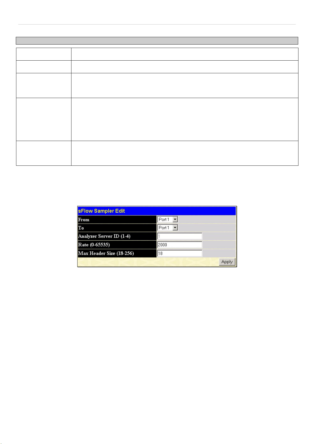
xStack DGS-3600 Series Layer 3 Gigabit Ethernet Managed Switch
The following fields may be set:
Parameter Description
From
To
Analyzer Server ID
Choose the beginning port of the range of ports to be configured for packet sampling.
Choose the ending port of the range of ports to be configured for packet sampling.
Enter the previously configured Analyzer Server ID to state the device that will be receiving
datagrams from the Switch. These datagrams will include the sample packet information taken
using the sampling mechanism configured here.
Rate
Users can set the rate of packet sampling here. The value entered here is to be multiplied by
256 to get the percentage of packets sampled. For example, if the user enters a figure of 20
into this field, the switch will sample one out of every 5120 packets (20 x 256 = 5120) that pass
through the individual port. Users may enter a value between 1 and 65535. An entry of 0
disables the packet sampling. Since this is the default setting, users are reminded to configure
a rate here or this function will not function.
Max Header Size
This field will set the number of leading bytes of the sampled packet header. This sampled
header will be encapsulated with the datagram to be forwarded to the Analyzer Server. The
user may set a value between 18 and 256 bytes. The default setting is 128 bytes.
Click Apply to save changes made.
To edit an entry that has already been configured, click the Modify button of an entry in the sFlow Sampler Settings window
which will produce the following window for the user to configure. This window holds the same information as the previous Add
window and therefore, the previous descriptions of the parameters remain valid here. Click Apply to save changes made to this
window.
Figure 6- 60. sFlow Sampler – Edit window
Please note that the Analyzer Server ID cannot be changed in this window. To change this setting, users must delete this entry and
configure a new entry with a new Analyzer server ID.
70
Page 88
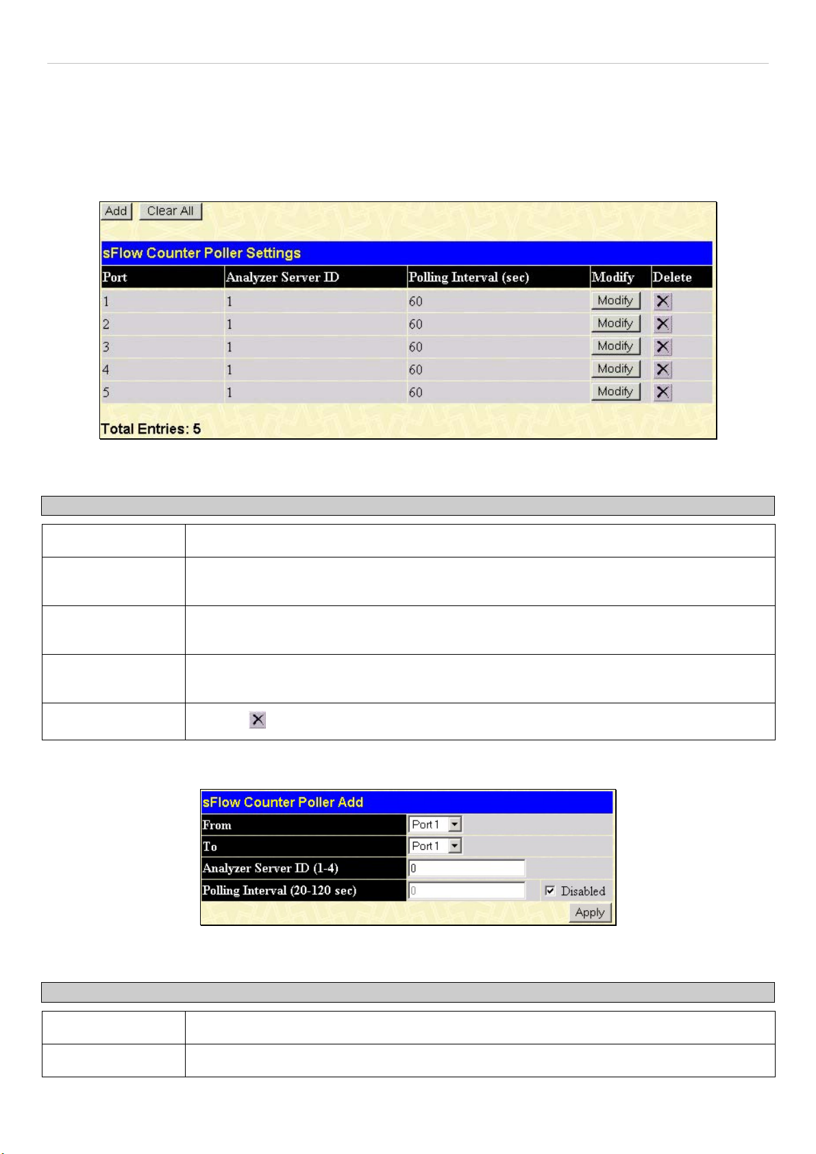
xStack DGS-3600 Series Layer 3 Gigabit Ethernet Managed Switch
sFlow Counter Poller Settings
The following windows will allow the user to configure the settings for the Switch’s counter poller. This mechanism will take a
poll of the IF counters of the Switch and them package them with the other previously mentioned data into a datagram which will
be sent to the sFlow Analyzer Server for examination. To configure the settings for the sFlow Counter Poller, click the
Administration link, open the sFlow folder and click sFlow Poller Settings, which will produce the following window,
displaying the parameters for the sFlow Counter Poller.
Figure 6- 61. sFlow Counter Poller Settings window
The following fields are displayed:
Parameter Description
Port
Analyzer Server ID
Polling Interval
Modify
Delete
To add a new sFlow Counter Poller setting, click the Add button in the previous window which will display the following window
to be configured:
Displays the port from which packet counter samples are being taken.
Displays the ID of the Analyzer Server where datagrams, containing the packet counter polling
information taken using this polling mechanism, will be sent.
The Polling Interval displayed here, is measured in seconds and will take a poll of the IF
counters for the corresponding port, every time the interval reaches 0 seconds.
Click this button to modify the settings for this entry. The sFlow Sampler Settings Edit
window will be produced for the user to configure.
Click the
of the corresponding entry to be deleted.
Figure 6- 62. sFlow Counter Poller – Add window
The following fields may be set:
Parameter Description
From
To
Choose the beginning port of the range of ports to be configured for counter polling.
Choose the ending port of the range of ports to be configured for counter polling.
71
Page 89

xStack DGS-3600 Series Layer 3 Gigabit Ethernet Managed Switch
Analyzer Server ID
Enter the previously configured Analyzer Server ID to state the device that will be receiving
datagrams from the Switch. These datagrams will include the counter poller information taken
using the polling mechanism configured here.
Polling Interval
Users may configure the Polling Interval here. The switch will take a poll of the IF counters
every time this interval reaches 0, and this information will be included in the sFlow datagrams
that will be sent to the sFlow Analyzer for examination. Checking the Disabled check box will
disable the counter polling for this entry.
Click Apply to save changes made.
To edit an entry that has already been configured, click the Modify button of an entry in the sFlow Sampler Settings window
which will produce the following window for the user to configure. This window holds the same information as the previous Add
window and therefore, the previous descriptions of the parameters remain valid here. Click Apply to save changes made to this
window.
Figure 6- 63. sFlow Counter Poller – Edit window
Please note that the Analyzer Server ID cannot be changed in this window. To change this setting, users must delete this entry and
configure a new entry with a new Analyzer server ID.
72
Page 90

xStack DGS-3600 Series Layer 3 Gigabit Ethernet Managed Switch
D-Link Single IP Management
Single IP Management (SIM) Overview
Simply put, D-Link Single IP Management is a concept that will stack switches together over Ethernet instead of using stacking
ports or modules. There are some advantages in implementing the "Single IP Management" feature:
1. SIM can simplify management of small workgroups or wiring closets while scaling the network to handle increased
bandwidth demand.
2. SIM can reduce the number of IP address needed in your network.
3. SIM can eliminate any specialized cables for stacking connectivity and remove the distance barriers that typically limit
your topology options when using other stacking technology.
Switches using D-Link Single IP Management (labeled here as SIM) must conform to the following rules:
•
SIM is an optional feature on the Switch and can easily be enabled or disabled through the Command Line Interface
or Web Interface. SIM grouping has no effect on the normal operation of the Switch in the user's network.
•
There are three classifications for SIM. The Commander Switch (CS), which is the master switch of the group,
Member Switch (MS), which is a switch that is recognized by the CS a member of a SIM group, and a Candidate
Switch (CaS), which is a Switch that has a physical link to the SIM group but has not been recognized by the CS as a
member of the SIM group.
•
A SIM group can only have one Commander Switch (CS).
•
All switches in a particular SIM group must be in the same IP subnet (broadcast domain). Members of a SIM group
cannot cross a router.
•
A SIM group accepts up to 33 switches (numbered 1-32), including the Commander Switch (numbered 0).
There is no limit to the number of SIM groups in the same IP subnet (broadcast domain), however a single switch can only belong
to one group.
If multiple VLANs are configured, the SIM group will only utilize the management VLAN on any switch.
SIM allows intermediate devices that do not support SIM. This enables the user to manage switches that are more than one hop
away from the CS.
The SIM group is a group of switches that are managed as a single entity. SIM switches may take on three different roles:
1. Commander Switch (CS) - This is a switch that has been manually configured as the controlling device for a group, and
takes on the following characteristics:
•
It has an IP Address.
•
It is not a commander switch or member switch of another Single IP group.
•
It is connected to the member switches through its management VLAN.
2. Member Switch (MS) - This is a switch that has joined a single IP group and is accessible from the CS, and it takes on
the following characteristics:
•
•
It is not a CS or MS of another Single IP group.
It is connected to the CS through the CS management VLAN.
3. Candidate Switch (CaS) - This is a switch that is ready to join a SIM group but is not yet a member of the SIM group.
The Candidate Switch may join the SIM group of a switch by manually configuring it to be a MS of a SIM group. A
switch configured as a CaS is not a member of a SIM group and will take on the following characteristics:
•
•
It is not a CS or MS of another Single IP group.
It is connected to the CS through the CS management VLAN
After configuring one switch to operate as the CS of a SIM group, additional switches may join the group through a direct
connection to the Commander switch. Only the Commander switch will allow entry to the candidate switch enabled for SIM. The
CS will then serve as the in band entry point for access to the MS. The CS's IP address will become the path to all MS's of the
group and the CS's Administrator's password, and/or authentication will control access to all MS's of the SIM group.
With SIM enabled, the applications in the CS will redirect the packet instead of executing the packets. The applications will
decode the packet from the administrator, modify some data, then send it to the MS. After execution, the CS may receive a
response packet from the MS, which it will encode and send it back to the administrator.
When a CaS becomes a MS, it automatically becomes a member of the first SNMP community (include read/write and read only)
to which the CS belongs. However, if a MS has its own IP address, it can belong to SNMP communities to which other switches
in the group, including the CS, do not belong.
73
Page 91
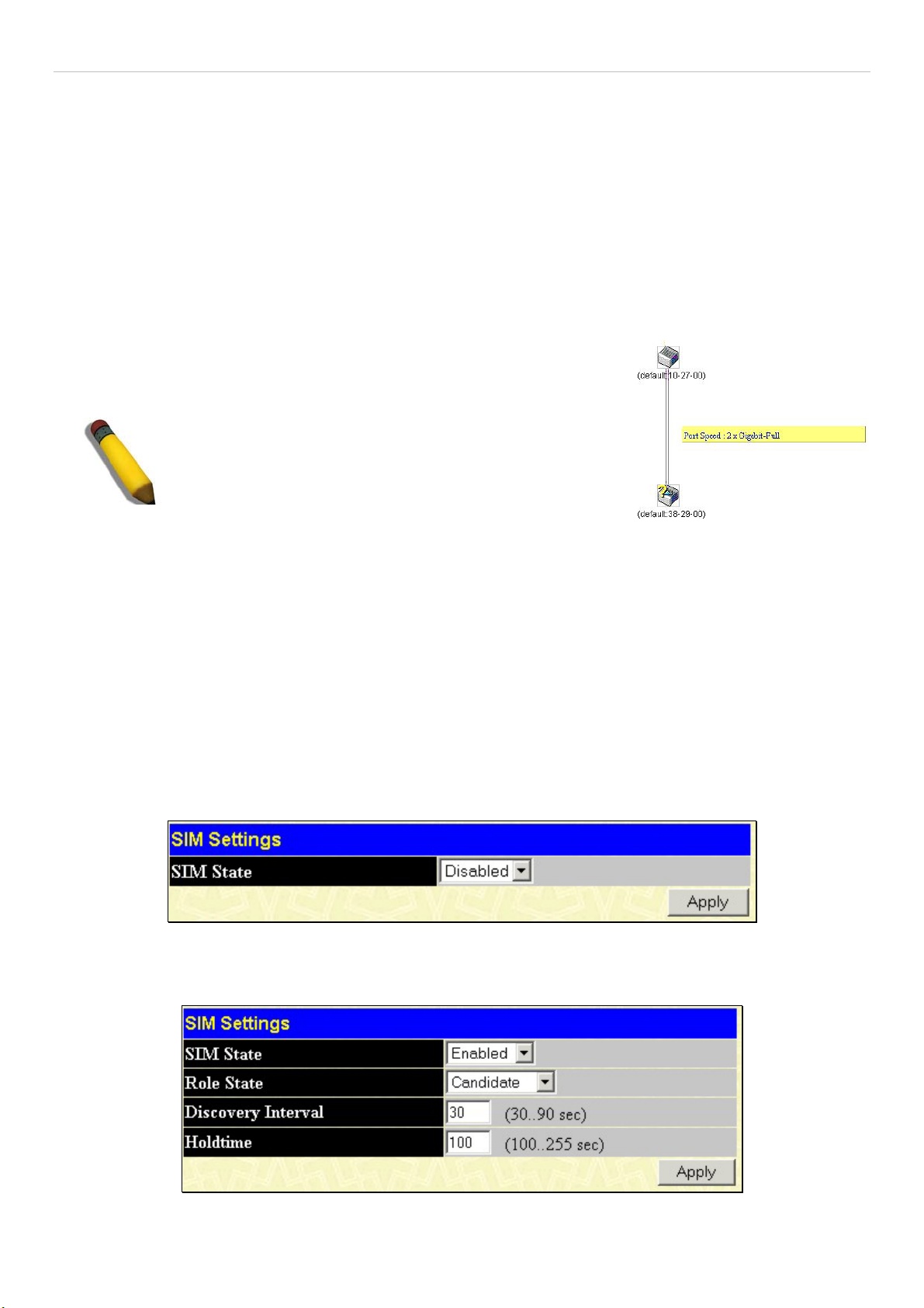
xStack DGS-3600 Series Layer 3 Gigabit Ethernet Managed Switch
The Upgrade to v1.6
To better improve SIM management, the xStack DGS-3600 Series switches have been upgraded to version 1.61 in this release.
Many improvements have been made, including:
1. The Commander Switch (CS) now has the capability to automatically rediscover member switches that have left the SIM
group, either through a reboot or web malfunction. This feature is accomplished through the use of Discover packets and Maintain
packets that previously set SIM members will emit after a reboot. Once a MS has had its MAC address and password saved to the
CS’s database, if a reboot occurs in the MS, the CS will keep this MS information in its database and when a MS has been
rediscovered, it will add the MS back into the SIM tree automatically. No configuration will be necessary to rediscover these
switches.
There are some instances where pre-saved MS switches cannot be rediscovered. For example, if the Switch is still powered down,
if it has become the member of another group, or if it has been configured to be a Commander Switch, the rediscovery process
cannot occur.
2. The topology map now includes new features for connections that are a member of
a port trunking group. It will display the speed and number of Ethernet connections
creating this port trunk group, as shown in the adjacent picture.
NOTE: For more details regarding improvements made
in SIMv1.6, please refer to the D-Link Single IP
Management White Paper located on the D-Link
website.
3. This version will support switch upload and downloads for firmware, configuration files and log files, as follows:
Firmware – The switch now supports MS firmware downloads from a TFTP server.
Configuration Files – This switch now supports downloading and uploading of configuration files both to (for configuration
restoration) and from (for configuration backup) MS’s, using a TFTP server..
Log – The switch now supports uploading MS log files to a TFTP server.
4. The user may zoom in and zoom out when utilizing the topology window to get a better, more defined view of the
configurations.
SIM Using the Web Interface
All switches are set as Candidate (CaS) switches as their factory default configuration and Single IP Management will be disabled.
To enable SIM for the Switch using the Web interface, go to the Single IP Management Settings folder, located in the
Administration folder, and click the SIM Settings link, revealing the following window.
Figure 6- 64. SIM Settings window (disabled)
Change the SIM State to Enabled using the pull down menu and click Apply. The screen will then refresh and the SIM Settings
window will look like this:
Figure 6- 65. SIM Settings window (enabled)
74
Page 92

xStack DGS-3600 Series Layer 3 Gigabit Ethernet Managed Switch
If the Switch Administrator wishes to configure the Switch as a Commander Switch (CS), select commander from the Role State
field and click Apply.
The following parameters can be set:
Parameters Description
SIM State
Use the pull down menu to either enable or disable the SIM state on the Switch. Disabled will
render all SIM functions on the Switch inoperable.
Role State
Use the pull down menu to change the SIM role of the Switch. The two choices are:
•
Candidate - A Candidate Switch (CaS) is not the member of a SIM group but is
connected to a Commander Switch. This is the default setting for the SIM role.
•
Commander - Choosing this parameter will make the Switch a Commander Switch
(CS). The user may join other switches to this Switch, over Ethernet, to be part of
its SIM group. Choosing this option will also enable the Switch to be configured for
SIM.
Discovery Interval
The user may set the discovery protocol interval, in seconds that the Switch will send out
discovery packets. Returning information to a Commander Switch will include information
about other switches connected to it. (Ex. MS, CaS). The user may set the Discovery Interval
from 30 to 90 seconds.
Holdtime
This parameter may be set for the time, in seconds the Switch will hold information sent to it
from other switches, utilizing the Discovery Interval. The user may set the hold time from 100
to 255 seconds.
Click Apply to implement the settings changed.
After enabling the Switch to be a Commander Switch (CS), the Single IP Management folder will then contain four added links
to aid the user in configuring SIM through the web, including Topology, Firmware Upgrade and Configuration
Backup/Restore and Upload Log File.
75
Page 93
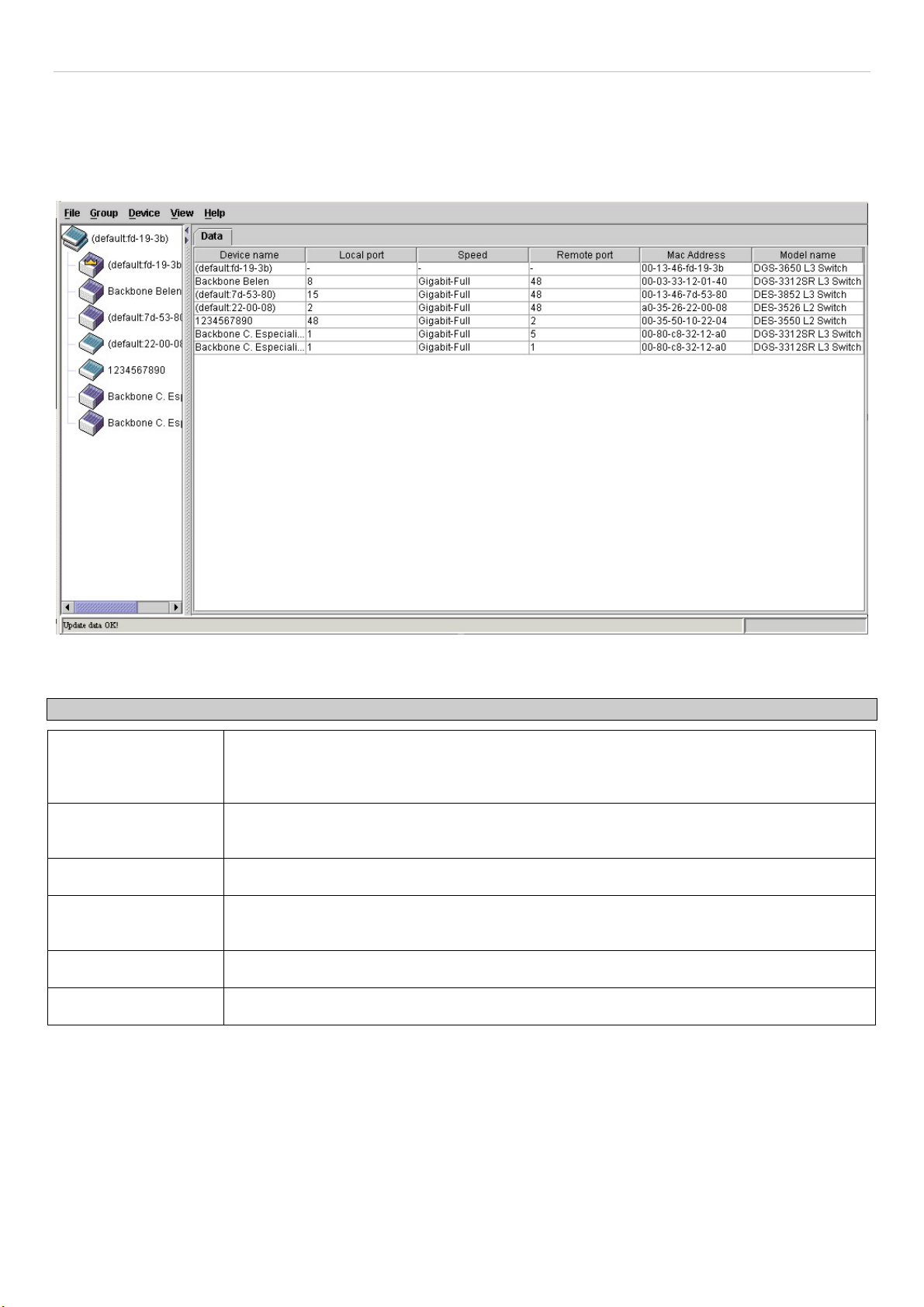
xStack DGS-3600 Series Layer 3 Gigabit Ethernet Managed Switch
Topology
The Topology window will be used to configure and manage the Switch within the SIM group and requires Java script to function
properly on your computer.
The Java Runtime Environment on your server should initiate and lead you to the topology window, as seen below.
Figure 6- 66. Single IP Management window - Tree View
The Tree View window holds the following information under the Data tab:
Parameter Description
Device Name
Local Port
Speed
Remote Port
MAC Address
Model Name
To view the Topology Map, click the View menu in the toolbar and then Topology, which will produce the following screen. The
Topology View will refresh itself periodically (20 seconds by default).
This field will display the Device Name of the switches in the SIM group configured by the
user. If no Device Name is configured by the name, it will be given the name default and
tagged with the last six digits of the MAC Address to identify it.
Displays the number of the physical port on the CS that the MS or CaS is connected to. The
CS will have no entry in this field.
Displays the connection speed between the CS and the MS or CaS.
Displays the number of the physical port on the MS or CaS that the CS is connected to. The
CS will have no entry in this field.
Displays the MAC Address of the corresponding Switch.
Displays the full Model Name of the corresponding Switch.
76
Page 94

xStack DGS-3600 Series Layer 3 Gigabit Ethernet Managed Switch
Figure 6- 67. Topology view
This window will display how the devices within the Single IP Management Group are connected to other groups and devices.
Possible icons in this screen are as follows:
Icon Description
Group
Layer 2 commander switch
Layer 3 commander switch
Commander switch of other group
Layer 2 member switch.
Layer 3 member switch
Member switch of other group
Layer 2 candidate switch
Layer 3 candidate switch
Unknown device
Non-SIM devices
77
Page 95

xStack DGS-3600 Series Layer 3 Gigabit Ethernet Managed Switch
Tool Tips
In the Topology view window, the mouse plays an important role in configuration and in viewing device information. Setting the
mouse cursor over a specific device in the topology window (tool tip) will display the same information about a specific device as
the Tree view does. See the window below for an example.
Figure 6- 68. Device Information Utilizing the Tool Tip
Setting the mouse cursor over a line between two devices will display the connection speed between the two devices, as shown
below.
Figure 6- 69. Port Speed Utilizing the Tool Tip
78
Page 96

xStack DGS-3600 Series Layer 3 Gigabit Ethernet Managed Switch
Right-Click
Right clicking on a device will allow the user to perform various functions, depending on the role of the Switch in the SIM group
and the icon associated with it.
Group Icon
Figure 6- 70. Right-Clicking a Group Icon
The following options may appear for the user to configure:
Collapse - To collapse the group that will be represented by a single icon. •
•
Expand - To expand the SIM group, in detail.
•
Property - To pop up a window to display the group information.
Figure 6- 71. Property window
This window holds the following information:
Parameter Description
Device Name This field will display the Device Name of the switches in the SIM group configured by the
user. If no Device Name is configured by the name, it will be given the name default and
tagged with the last six digits of the MAC Address to identify it.
Module Name
MAC Address
Remote Port No. Displays the number of the physical port on the MS or CaS that the CS is connected to. The
Local Port No. Displays the number of the physical port on the CS that the MS or CaS is connected to. The
Port Speed
Click Close to close the Property window.
Displays the full module name of the switch that was right-clicked.
Displays the MAC Address of the corresponding Switch.
CS will have no entry in this field.
CS will have no entry in this field.
Displays the connection speed between the CS and the MS or CaS
79
Page 97

xStack DGS-3600 Series Layer 3 Gigabit Ethernet Managed Switch
Commander Switch Icon
Figure 6- 72. Right Clicking a Commander Icon
The following options may appear for the user to configure:
Collapse - To collapse the group that will be represented by a single icon. •
•
Expand - To expand the SIM group, in detail.
•
Property - To pop up a window to display the group information.
Member Switch Icon
Figure 6- 73. Right-Clicking a Member icon
The following options may appear for the user to configure:
Collapse - To collapse the group that will be represented by a single icon. •
•
Expand - To expand the SIM group, in detail.
•
Remove from group - Remove a member from a group.
•
Configure - Launch the web management to configure the Switch.
•
Property - To pop up a window to display the device information.
Candidate Switch Icon
Figure 6- 74. Right-Clicking a Candidate icon
The following options may appear for the user to configure:
Collapse - To collapse the group that will be represented by a single icon. •
• Expand - To expand the SIM group, in detail.
80
Page 98

xStack DGS-3600 Series Layer 3 Gigabit Ethernet Managed Switch
Add to group - Add a candidate to a group. Clicking this option will reveal the following window for the user to
•
enter a password for authentication from the Candidate Switch before being added to the SIM group. Click OK to
enter the password or Cancel to exit the window.
Figure 6- 75. Input password window
Property - To pop up a window to display the device information. •
Menu Bar
The Single IP Management window contains a menu bar for device configurations, as seen below.
Figure 6- 76. Menu Bar of the Topology View
The five menus on the menu bar are as follows.
File
Print Setup - Will view the image to be printed. •
•
Print Topology - Will print the topology map.
•
Preference - Will set display properties, such as polling interval, and the views to open at SIM startup.
Group
•
Add to group - Add a candidate to a group. Clicking this option will reveal the following screen for the user to enter
a password for authentication from the Candidate Switch before being added to the SIM group. Click OK to enter
the password or Cancel to exit the window.
Figure 6- 77. Input password window
Remove from Group - Remove an MS from the group. •
Device
•
View
•
•
Help
•
Configure - Will open the web manager for the specific device.
Refresh - Update the views with the latest status.
Topology - Display the Topology view.
About - Will display the SIM information, including the current SIM version.
81
Page 99

xStack DGS-3600 Series Layer 3 Gigabit Ethernet Managed Switch
NOTE: Upon this firmware release, some functions of the SIM can only be
configured through the Command Line Interface. See the DGS-3600 CLI
Manual for more information on SIM and its configurations.
Firmware Upgrade
This screen is used to upgrade firmware from the Commander Switch to the Member Switch. To access the following window,
click Administration > Single IP Management Settings > Firmware Upgrade. Member Switches will be listed in the table and
will be specified by Port (port on the CS where the MS resides), MAC Address, Model Name and Version. To specify a certain
Switch for firmware download, click its corresponding check box under the Port heading. To update the firmware, enter the
Server IP Address where the firmware resides and enter the Path/Filename of the firmware. Click Download to initiate the file
transfer.
Figure 6- 78. Firmware Upgrade window
Configuration File Backup/Restore
This screen is used to upgrade configuration files from the Commander Switch to the Member Switch using a TFTP server.
Member Switches will be listed in the table and will be specified by Port (port on the CS where the MS resides), MAC Address,
Model Name and Version. To specify a certain Switch for upgrading configuration files, click its corresponding radio button
under the Port heading. To update the configuration file, enter the Server IP Address where the file resides and enter the
Path/Filename of the configuration file. Click Download to initiate the file transfer from a TFTP server to the Switch. Click
Upload to backup the configuration file to a TFTP server. To access the following window, click Administration > Single IP
Management Settings > Configuration Backup/Restore.
Figure 6- 79. Configuration File Backup/Restore window
82
Page 100
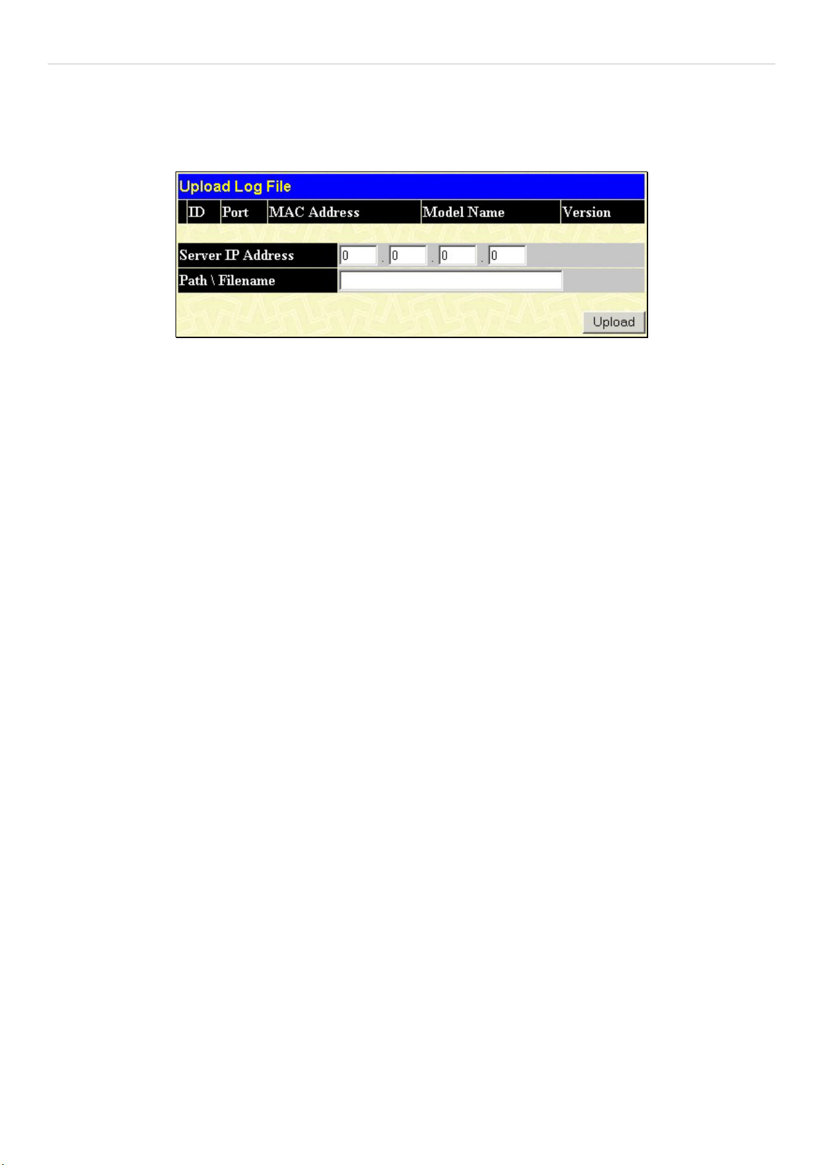
xStack DGS-3600 Series Layer 3 Gigabit Ethernet Managed Switch
Upload Log File
The following window is used to upload log files from SIM member switches to a specified PC. To view this window click
Administration > Single IP Management > Upload Log File. To upload a log file, enter the IP address of the SIM member
switch and then enter a path on your PC where you wish to save this file. Click Upload to initiate the file transfer.
Figure 6- 80. Upload Log File window
83
 Loading...