

D-Link DGS-3620-28SC-EI, DGS-3620-52P-SI, DGS-3620-28TC-SI, DGS-3620-52P-EI, DGS-3620-52T-EI Product Manual
...Page 1
Page 2

xStack® DGS-3620 Series Managed Switch Web UI Reference Guide
i
Information in this document is subject to change without notice.
© 2011 D-Link Corporation. All rights reserved.
Reproduction of this document in any manner whatsoever without the written permission of D-Link Corporation is strictly forbidden.
Trademarks used in this text: D-Link and the D-LINK logo are trademarks of D-Link Corporation; Microsoft and Windows are registered
trademarks of Microsoft Corporation.
Other trademarks and trade names may be used in this document to refer to either the entities claiming the marks and names or their products.
D-Link Corporation disclaims any proprietary interest in trademarks and trade names other than its own.
February 2011 P/N 651GS3620015G
Page 3

xStack® DGS-3620 Series Managed Switch Web UI Reference Guide
ii
Table of Contents
Intended Readers ............................................................................................................................................................ 1
Typographical Conventions ............................................................................................................................................. 1
Notes, Notices and Cautions........................................................................................................................................... 1
Safety Instructions ........................................................................................................................................................... 1
Safety Cautions ........................................................................................................................................................... 2
General Precautions for Rack-Mountable Products........................................................................................................ 3
Protecting Against Electrostatic Discharge ..................................................................................................................... 4
Chapter 1 Web-based Switch Configuration ........................................................................... 5
Introduction ...................................................................................................................................................................... 5
Login to the Web Manager .............................................................................................................................................. 5
Web-based User Interface .............................................................................................................................................. 6
Areas of the User Interface.......................................................................................................................................... 6
Web Pages ...................................................................................................................................................................... 7
Chapter 2 System Configuration .............................................................................................. 8
Device Information .......................................................................................................................................................... 8
System Information Settings ........................................................................................................................................... 9
Port Configuration ......................................................................................................................................................... 10
Port Settings .............................................................................................................................................................. 10
Port Description Settings ........................................................................................................................................... 11
Port Error Disabled .................................................................................................................................................... 12
Port Auto Negotiation Information ............................................................................................................................. 13
Jumbo Frame Settings .............................................................................................................................................. 14
PoE ................................................................................................................................................................................ 14
PoE System Settings ................................................................................................................................................. 15
PoE Port Settings ...................................................................................................................................................... 16
Serial Port Settings ....................................................................................................................................................... 17
Warning Temperature Settings ..................................................................................................................................... 17
System Log configuration .............................................................................................................................................. 18
System Log Settings .................................................................................................................................................. 18
System Log Server Settings ...................................................................................................................................... 18
System Log ................................................................................................................................................................ 19
System Log & Trap Settings ...................................................................................................................................... 20
System Severity Settings ........................................................................................................................................... 21
Time Range Settings ..................................................................................................................................................... 21
Port Group Settings ....................................................................................................................................................... 22
Time Settings ................................................................................................................................................................ 22
User Accounts Settings ................................................................................................................................................. 23
Command Logging Settings .......................................................................................................................................... 24
Stacking ......................................................................................................................................................................... 24
Stacking Device Table ............................................................................................................................................... 26
Stacking Mode Settings ............................................................................................................................................. 26
Chapter 3 Management ........................................................................................................... 28
ARP ............................................................................................................................................................................... 28
Static ARP Settings ................................................................................................................................................... 28
Proxy ARP Settings ................................................................................................................................................... 29
ARP Table ................................................................................................................................................................. 29
Gratuitous ARP ............................................................................................................................................................. 30
Page 4

xStack® DGS-3620 Series Managed Switch Web UI Reference Guide
iii
Gratuitous ARP Global Settings ................................................................................................................................ 30
Gratuitous ARP Settings ............................................................................................................................................ 30
IPv6 Neighbor Settings ................................................................................................................................................. 31
IP Interface .................................................................................................................................................................... 32
System IP Address Settings ...................................................................................................................................... 32
Interface Settings ....................................................................................................................................................... 33
Loopback Interface Settings ...................................................................................................................................... 37
Management Settings ................................................................................................................................................... 38
Out of Band Management Settings ............................................................................................................................... 39
Session Table................................................................................................................................................................ 39
Single IP Management .................................................................................................................................................. 40
Single IP Settings ...................................................................................................................................................... 41
Topology .................................................................................................................................................................... 42
Firmware Upgrade ..................................................................................................................................................... 48
Configuration File Backup/Restore ............................................................................................................................ 49
Upload Log File ......................................................................................................................................................... 49
SNMP Settings .............................................................................................................................................................. 49
SNMP Global Settings ............................................................................................................................................... 50
SNMP Traps Settings ................................................................................................................................................ 51
SNMP Linkchange Traps Settings ............................................................................................................................ 51
SNMP View Table Settings ....................................................................................................................................... 52
SNMP Community Table Settings ............................................................................................................................. 53
SNMP Group Table Settings ..................................................................................................................................... 54
SNMP Engine ID Settings ......................................................................................................................................... 55
SNMP User Table Settings........................................................................................................................................ 55
SNMP Host Table Settings ........................................................................................................................................ 56
SNMPv6 Host Table Settings .................................................................................................................................... 57
RMON Settings .......................................................................................................................................................... 58
SNMP Community Encryption Settings ..................................................................................................................... 58
SNMP Community Masking Settings ........................................................................................................................ 58
Telnet Settings .............................................................................................................................................................. 59
Web Settings ................................................................................................................................................................. 59
Chapter 4 L2 Features ............................................................................................................. 61
VLAN ............................................................................................................................................................................. 61
802.1Q VLAN Settings .............................................................................................................................................. 66
802.1v Protocol VLAN ............................................................................................................................................... 69
Asymmetric VLAN Settings ....................................................................................................................................... 71
GVRP ......................................................................................................................................................................... 71
MAC-based VLAN Settings ....................................................................................................................................... 73
Private VLAN Settings ............................................................................................................................................... 73
PVID Auto Assign Settings ........................................................................................................................................ 75
Subnet VLAN ............................................................................................................................................................. 75
Super VLAN ............................................................................................................................................................... 77
Voice VLAN ............................................................................................................................................................... 79
VLAN Trunk Settings ................................................................................................................................................. 82
Browse VLAN ............................................................................................................................................................ 83
Show VLAN Ports ...................................................................................................................................................... 83
QinQ .............................................................................................................................................................................. 83
QinQ Settings ............................................................................................................................................................ 85
VLAN Translation Settings ........................................................................................................................................ 86
Page 5

xStack® DGS-3620 Series Managed Switch Web UI Reference Guide
iv
Layer 2 Protocol Tunneling Settings ............................................................................................................................. 87
Spanning Tree ............................................................................................................................................................... 87
STP Bridge Global Settings ....................................................................................................................................... 89
STP Port Settings ...................................................................................................................................................... 91
MST Configuration Identification ............................................................................................................................... 92
STP Instance Settings ............................................................................................................................................... 93
MSTP Port Information .............................................................................................................................................. 93
Link Aggregation ........................................................................................................................................................... 94
Port Trunking Settings ............................................................................................................................................... 96
LACP Port Settings .................................................................................................................................................... 96
FDB ............................................................................................................................................................................... 97
Static FDB Settings ................................................................................................................................................... 97
MAC Notification Settings .......................................................................................................................................... 99
MAC Address Aging Time Settings ......................................................................................................................... 100
MAC Address Table ................................................................................................................................................ 100
ARP & FDB Table .................................................................................................................................................... 101
L2 Multicast Control .................................................................................................................................................... 102
IGMP Proxy ............................................................................................................................................................. 102
IGMP Snooping ....................................................................................................................................................... 104
MLD Proxy ............................................................................................................................................................... 111
MLD Snooping ......................................................................................................................................................... 112
Multicast VLAN ........................................................................................................................................................ 120
Multicast Filtering ........................................................................................................................................................ 126
IPv4 Multicast Filtering ............................................................................................................................................ 126
IPv6 Multicast Filtering ............................................................................................................................................ 128
Multicast Filtering Mode ........................................................................................................................................... 131
ERPS Settings............................................................................................................................................................. 131
LLDP ........................................................................................................................................................................... 135
LLDP ........................................................................................................................................................................ 135
LLDP-MED............................................................................................................................................................... 143
NLB FDB Settings ....................................................................................................................................................... 145
PTP ............................................................................................................................................................................. 146
PTP Global Settings ................................................................................................................................................ 146
PTP Port Settings .................................................................................................................................................... 147
PTP Boundary Clock Settings ................................................................................................................................. 148
PTP Boundary Port Settings ................................................................................................................................... 149
PTP Peer to Peer Transparent Port Settings .......................................................................................................... 150
PTP Clock Information ............................................................................................................................................. 151
PTP Port Information ............................................................................................................................................... 151
PTP Foreign Master Records Port Information ....................................................................................................... 151
Chapter 5 L3 Features ........................................................................................................... 153
IPv4 Static/Default Route Settings .............................................................................................................................. 153
IPv4 Route Table ........................................................................................................................................................ 154
IPv6 Static/Default Route Settings .............................................................................................................................. 155
IPv6 Route Table ........................................................................................................................................................ 156
Policy Route Settings .................................................................................................................................................. 156
IP Forwarding Table .................................................................................................................................................... 157
IP Multicast Forwarding Table ..................................................................................................................................... 157
IP Multicast Interface Table ......................................................................................................................................... 158
Static Multicast Route Settings ................................................................................................................................... 158
Page 6

xStack® DGS-3620 Series Managed Switch Web UI Reference Guide
v
Route Preference Settings .......................................................................................................................................... 159
ECMP Algorithm Settings ............................................................................................................................................ 159
Route Redistribution Settings ...................................................................................................................................... 160
IP Tunnel (EI Mode Only) ............................................................................................................................................ 161
IP Tunnel Settings ................................................................................................................................................... 161
IP Tunnel GRE Settings .......................................................................................................................................... 162
OSPF ........................................................................................................................................................................... 163
OSPFv2 ................................................................................................................................................................... 183
OSPFv3 (EI Mode Only) .......................................................................................................................................... 190
RIP .............................................................................................................................................................................. 197
RIP Settings ............................................................................................................................................................. 198
RIPng (EI Mode Only) ............................................................................................................................................. 200
IP Multicast Routing Protocol ...................................................................................................................................... 201
IGMP ........................................................................................................................................................................ 201
MLD ......................................................................................................................................................................... 206
DVMRP (EI Mode Only) .......................................................................................................................................... 208
PIM .......................................................................................................................................................................... 210
VRRP .......................................................................................................................................................................... 228
VRRP Global Settings ............................................................................................................................................. 228
VRRP Virtual Router Settings.................................................................................................................................. 229
VRRP Authentication Settings ................................................................................................................................. 231
BGP (EI Mode Only) ................................................................................................................................................... 232
BGP Global Settings ................................................................................................................................................ 232
BGP Aggregate Address Settings ........................................................................................................................... 234
BGP Network Settings ............................................................................................................................................. 234
BGP Dampening Settings........................................................................................................................................ 235
BGP Peer Group Settings ....................................................................................................................................... 236
BGP Neighbor ......................................................................................................................................................... 237
BGP Reflector Settings ............................................................................................................................................ 245
BGP Confederation Settings ................................................................................................................................... 246
BGP AS Path Access Settings ................................................................................................................................ 247
BGP Community List Settings ................................................................................................................................. 248
BGP Trap Settings ................................................................................................................................................... 249
BGP Clear Settings ................................................................................................................................................. 249
BGP Summary Table ............................................................................................................................................... 250
BGP Routing Table .................................................................................................................................................. 251
BGP Dampened Route Table .................................................................................................................................. 252
BGP Flap Statistic Table ......................................................................................................................................... 252
IP Route Filter ............................................................................................................................................................. 253
IP Prefix List Settings .............................................................................................................................................. 253
IP Standard Access List Settings ............................................................................................................................ 254
Route Map Settings ................................................................................................................................................. 255
MD5 Settings ............................................................................................................................................................... 258
IGMP Static Group Settings ........................................................................................................................................ 259
Chapter 6 QoS ........................................................................................................................ 260
802.1p Settings ........................................................................................................................................................... 261
802.1p Default Priority Settings ............................................................................................................................... 261
802.1p User Priority Settings ................................................................................................................................... 262
Bandwidth Control ....................................................................................................................................................... 263
Bandwidth Control Settings ..................................................................................................................................... 263
Page 7

xStack® DGS-3620 Series Managed Switch Web UI Reference Guide
vi
Queue Bandwidth Control Settings ......................................................................................................................... 265
Traffic Control Settings ................................................................................................................................................ 265
HOL Blocking Prevention ............................................................................................................................................ 268
Scheduling Settings .................................................................................................................................................... 268
QoS Scheduling ....................................................................................................................................................... 268
QoS Scheduling Mechanism ................................................................................................................................... 269
Chapter 7 ACL ........................................................................................................................ 271
ACL Configuration Wizard ........................................................................................................................................... 271
Access Profile List ....................................................................................................................................................... 272
CPU Access Profile List .............................................................................................................................................. 288
ACL Finder .................................................................................................................................................................. 302
ACL Flow Meter........................................................................................................................................................... 302
Egress Access Profile List ........................................................................................................................................... 305
Egress ACL Flow Meter .............................................................................................................................................. 317
Chapter 8 Security ................................................................................................................. 320
802.1X ......................................................................................................................................................................... 320
802.1X Global Settings ............................................................................................................................................ 323
802.1X Port Settings ................................................................................................................................................ 324
802.1X User Settings ............................................................................................................................................... 325
Guest VLAN Settings ............................................................................................................................................... 326
Authenticator State .................................................................................................................................................. 327
Authenticator Statistics ............................................................................................................................................ 328
Authenticator Session Statistics .............................................................................................................................. 328
Authenticator Diagnostics ........................................................................................................................................ 329
Initialize Port-based Port(s) ..................................................................................................................................... 330
Initialize Host-based Port(s) .................................................................................................................................... 331
Reauthenticate Port-based Port(s) .......................................................................................................................... 331
Reauthenticate Host-based Port(s) ......................................................................................................................... 331
RADIUS ....................................................................................................................................................................... 332
Authentication RADIUS Server Settings ................................................................................................................. 332
RADIUS Accounting Settings .................................................................................................................................. 333
RADIUS Authentication ........................................................................................................................................... 333
RADIUS Account Client ........................................................................................................................................... 335
IP-MAC-Port Binding (IMPB) ....................................................................................................................................... 336
IMPB Global Settings .............................................................................................................................................. 336
IMPB Port Settings .................................................................................................................................................. 337
IMPB Entry Settings ................................................................................................................................................ 338
MAC Block List ........................................................................................................................................................ 339
DHCP Snooping ...................................................................................................................................................... 339
ND Snooping ........................................................................................................................................................... 341
MAC-based Access Control (MAC)............................................................................................................................. 342
MAC-based Access Control Settings ...................................................................................................................... 343
MAC-based Access Control Local Settings ............................................................................................................. 344
MAC-based Access Control Authentication State ................................................................................................... 345
Web-based Access Control (WAC) ............................................................................................................................. 345
WAC Global Settings ............................................................................................................................................... 348
WAC User Settings .................................................................................................................................................. 349
WAC Port Settings ................................................................................................................................................... 349
WAC Authentication State ....................................................................................................................................... 350
WAC Customize Page ............................................................................................................................................. 351
Page 8

xStack® DGS-3620 Series Managed Switch Web UI Reference Guide
vii
Japanese Web-based Access Control (JWAC) .......................................................................................................... 353
JWAC Global Settings ............................................................................................................................................. 353
JWAC Port Settings ................................................................................................................................................. 355
JWAC User Settings ................................................................................................................................................ 356
JWAC Authentication State ..................................................................................................................................... 357
JWAC Customize Page Language .......................................................................................................................... 357
JWAC Customize Page ........................................................................................................................................... 358
Compound Authentication ........................................................................................................................................... 358
Compound Authentication Settings ......................................................................................................................... 358
Compound Authentication Guest VLAN Settings .................................................................................................... 360
Compound Authentication MAC Format Settings ................................................................................................... 360
Port Security ................................................................................................................................................................ 361
Port Security Settings .............................................................................................................................................. 361
Port Security VLAN Settings ................................................................................................................................... 363
Port Security Entries ................................................................................................................................................ 364
ARP Spoofing Prevention Settings ............................................................................................................................. 364
BPDU Attack Protection .............................................................................................................................................. 365
Loopback Detection Settings ...................................................................................................................................... 367
Traffic Segmentation Settings ..................................................................................................................................... 368
NetBIOS Filtering Settings .......................................................................................................................................... 369
DHCP Server Screening ............................................................................................................................................. 370
DHCP Server Screening Port Settings .................................................................................................................... 370
DHCP Offer Permit Entry Settings .......................................................................................................................... 371
Access Authentication Control .................................................................................................................................... 371
Enable Admin .......................................................................................................................................................... 372
Authentication Policy Settings ................................................................................................................................. 373
Application Authentication Settings ......................................................................................................................... 374
Authentication Server Group Settings ..................................................................................................................... 374
Authentication Server Settings ................................................................................................................................ 376
Login Method Lists Settings .................................................................................................................................... 377
Enable Method Lists Settings .................................................................................................................................. 378
Local Enable Password Settings ............................................................................................................................. 379
SSL Settings................................................................................................................................................................ 379
SSH ............................................................................................................................................................................. 382
SSH Settings ........................................................................................................................................................... 382
SSH Authentication Method and Algorithm Settings ............................................................................................... 383
SSH User Authentication List .................................................................................................................................. 385
Trusted Host Settings .................................................................................................................................................. 386
Safeguard Engine Settings ......................................................................................................................................... 386
Chapter 9 Network Application ............................................................................................ 389
DHCP .......................................................................................................................................................................... 389
DHCP Relay ............................................................................................................................................................ 389
DHCP Server ........................................................................................................................................................... 394
DHCPv6 Server ....................................................................................................................................................... 398
DHCPv6 Relay ........................................................................................................................................................ 402
DHCP Local Relay Settings..................................................................................................................................... 403
DNS ............................................................................................................................................................................. 403
DNS Relay ............................................................................................................................................................... 404
DNS Resolver.............................................................................................................................................................. 405
DNS Resolver Global Settings ................................................................................................................................ 405
Page 9

xStack® DGS-3620 Series Managed Switch Web UI Reference Guide
viii
DNS Resolver Static Name Server Settings ........................................................................................................... 405
DNS Resolver Dynamic Name Server Table .......................................................................................................... 406
DNS Resolver Static Host Name Settings ............................................................................................................... 406
DNS Resolver Dynamic Host Name Table .............................................................................................................. 407
RCP Server Settings ................................................................................................................................................... 407
SNTP ........................................................................................................................................................................... 407
SNTP Settings ......................................................................................................................................................... 407
Time Zone Settings ................................................................................................................................................. 408
Flash File System Settings .......................................................................................................................................... 410
Chapter 10 OAM ....................................................................................................................... 412
CFM (EI Mode Only) ................................................................................................................................................... 412
CFM Settings ........................................................................................................................................................... 412
CFM Port Settings ................................................................................................................................................... 418
CFM MIPCCM Table ............................................................................................................................................... 419
CFM Loopback Settings .......................................................................................................................................... 419
CFM Linktrace Settings ........................................................................................................................................... 420
CFM Packet Counter ............................................................................................................................................... 421
CFM Fault Table ...................................................................................................................................................... 421
CFM MP Table ........................................................................................................................................................ 422
Ethernet OAM.............................................................................................................................................................. 422
Ethernet OAM Settings ............................................................................................................................................ 422
Ethernet OAM Configuration Settings ..................................................................................................................... 423
Ethernet OAM Event Log......................................................................................................................................... 424
Ethernet OAM Statistics .......................................................................................................................................... 425
DULD Settings............................................................................................................................................................. 426
Cable Diagnostics (EI Mode Only) .............................................................................................................................. 427
Chapter 11 Monitoring ............................................................................................................ 429
Utilization ..................................................................................................................................................................... 429
CPU Utilization ........................................................................................................................................................ 429
DRAM & Flash Utilization ........................................................................................................................................ 430
Port Utilization ......................................................................................................................................................... 430
Statistics ...................................................................................................................................................................... 431
Port Statistics ........................................................................................................................................................... 431
Packet Size .............................................................................................................................................................. 438
Mirror ........................................................................................................................................................................... 440
Port Mirror Settings .................................................................................................................................................. 440
RSPAN Settings ...................................................................................................................................................... 441
sFlow ........................................................................................................................................................................... 442
sFlow Global Settings .............................................................................................................................................. 442
sFlow Analyzer Server Settings .............................................................................................................................. 443
sFlow Flow Sampler Settings .................................................................................................................................. 444
sFlow Counter Poller Settings ................................................................................................................................. 444
Ping ............................................................................................................................................................................. 445
Broadcast Ping Relay Settings ................................................................................................................................ 445
Ping Test.................................................................................................................................................................. 445
Trace Route................................................................................................................................................................. 447
Peripheral .................................................................................................................................................................... 448
Device Environment ................................................................................................................................................ 448
Chapter 12 Save and Tools ..................................................................................................... 449
Save Configuration / Log ............................................................................................................................................. 449
Page 10

xStack® DGS-3620 Series Managed Switch Web UI Reference Guide
ix
Stacking Information ................................................................................................................................................... 449
Download Firmware .................................................................................................................................................... 451
Download Firmware from TFTP .............................................................................................................................. 451
Download Firmware from RCP ................................................................................................................................ 451
Download Firmware from HTTP .............................................................................................................................. 452
Upload Firmware ......................................................................................................................................................... 452
Upload Firmware to TFTP ....................................................................................................................................... 452
Upload Firmware to RCP ......................................................................................................................................... 453
Upload Firmware to HTTP ....................................................................................................................................... 454
Download Configuration .............................................................................................................................................. 454
Download Configuration from TFTP ........................................................................................................................ 454
Download Configuration from RCP ......................................................................................................................... 455
Download Configuration from HTTP ....................................................................................................................... 455
Upload Configuration .................................................................................................................................................. 456
Upload Configuration to TFTP ................................................................................................................................. 456
Upload Configuration to RCP .................................................................................................................................. 456
Upload Configuration to HTTP ................................................................................................................................ 457
Upload Log File ........................................................................................................................................................... 458
Upload Log to TFTP ................................................................................................................................................ 458
Upload Log to RCP .................................................................................................................................................. 458
Upload Log to HTTP ................................................................................................................................................ 459
Reset ........................................................................................................................................................................... 459
Reboot System ............................................................................................................................................................ 460
Appendices 461
Appendix A Mitigating ARP Spoofing Attacks Using Packet Content ACL ............................................................ 461
Appendix B Password Recovery Procedure .......................................................................................................... 467
Appendix C System Log Entries ............................................................................................................................. 468
Appendix D Trap Entries ........................................................................................................................................ 488
Page 11
xStack® DGS-3620 Series Managed Switch Web UI Reference Guide
1
Intended Readers
Typographical Conventions
Notes, Notices and Cautions
Safety Instructions
General Precautions for Rack-Mountable Products
Protecting Against Electrostatic Discharge
The DGS-3620 Series Web UI Reference Guide contains information for setup and management of the Switch.
This manual is intended for network managers familiar with network management concepts and terminology.
Typographical Conventions
Convention Description
[ ] In a command line, square brackets indicate an optional entry. For example: [copy
filename] means that optionally you can type copy followed by the name of the file.
Do not type the brackets.
Bold font Indicates a button, a toolbar icon, menu, or menu item. For example: Open the File
menu and choose Cancel. Used for emphasis. May also indicate system messages
or prompts appearing on screen. For example: You have mail. Bold font is also
used to represent filenames, program names and commands. For example: use the
copy command.
Boldface Typewriter
Font
Indicates commands and responses to prompts that must be typed exactly as
printed in the manual.
Initial capital letter Indicates a window name. Names of keys on the keyboard have initial capitals. For
example: Click Enter.
Menu Name > Menu
Option
Menu Name > Menu Option Indicates the menu structure. Device > Port > Port
Properties means the Port Properties menu option under the Port menu option that
is located under the Device menu.
Notes, Notices and Cautions
A NOTE indicates important information that helps make better use of the device.
A NOTICE indicates either potential damage to hardware or loss of data and tells how to avoid the
problem.
A CAUTION indicates a potential for property damage, personal injury, or death.
Safety Instructions
Use the following safety guidelines to ensure your own personal safety and to help protect your system from
potential damage. Throughout this safety section, the caution icon (
) is used to indicate cautions and
precautions that need to be reviewed and followed.
Page 12

xStack® DGS-3620 Series Managed Switch Web UI Reference Guide
2
Safety Cautions
To reduce the risk of bodily injury, electrical shock, fire, and damage to the equipment observe the following
precautions:
• Observe and follow service markings.
o Do not service any product except as explained in the system documentation.
o Opening or removing covers that are marked with the triangular symbol with a lightning bolt may
expose the user to electrical shock.
o Only a trained service technician should service components inside these compartments.
• If any of the following conditions occur, unplug the product from the electrical outlet and replace the part or
contact your trained service provider:
o Damage to the power cable, extension cable, or plug.
o An object has fallen into the product.
o The product has been exposed to water.
o The product has been dropped or damaged.
o The product does not operate correctly when the operating instructions are correctly followed.
• Keep your system away from radiators and heat sources. Also, do not block cooling vents.
• Do not spill food or liquids on system components, and never operate the product in a wet environment. If
the system gets wet, see the appropriate section in the troubleshooting guide or contact your trained service
provider.
• Do not push any objects into the openings of the system. Doing so can cause fire or electric shock by
shorting out interior components.
• Use the product only with approved equipment.
• Allow the product to cool before removing covers or touching internal components.
• Operate the product only from the type of external power source indicated on the electrical ratings label. If
unsure of the type of power source required, consult your service provider or local power company.
• To help avoid damaging the system, be sure the voltage selection switch (if provided) on the power supply
is set to match the power available at the Switch’s location:
o 115 volts (V)/60 hertz (Hz) in most of North and South America and some Far Eastern countries
such as South Korea and Taiwan
o 100 V/50 Hz in eastern Japan and 100 V/60 Hz in western Japan
o 230 V/50 Hz in most of Europe, the Middle East, and the Far East
• Also, be sure that attached devices are electrically rated to operate with the power available in your
location.
• Use only approved power cable(s). If you have not been provided with a power cable for your system or for
any AC-powered option intended for your system, purchase a power cable that is approved for use in your
country. The power cable must be rated for the product and for the voltage and current marked on the
product's electrical ratings label. The voltage and current rating of the cable should be greater than the
ratings marked on the product.
• To help prevent electric shock, plug the system and peripheral power cables into properly grounded
electrical outlets. These cables are equipped with three-prong plugs to help ensure proper grounding. Do
not use adapter plugs or remove the grounding prong from a cable. If using an extension cable is
necessary, use a 3-wire cable with properly grounded plugs.
• Observe extension cable and power strip ratings. Make sure that the total ampere rating of all products
plugged into the extension cable or power strip does not exceed 80 percent of the ampere ratings limit for
the extension cable or power strip.
• To help protect the system from sudden, transient increases and decreases in electrical power, use a surge
suppressor, line conditioner, or uninterruptible power supply (UPS).
• Position system cables and power cables carefully; route cables so that they cannot be stepped on or
tripped over. Be sure that nothing rests on any cables.
• Do not modify power cables or plugs. Consult a licensed electrician or your power company for site
modifications. Always follow your local/national wiring rules.
• When connecting or disconnecting power to hot-pluggable power supplies, if offered with your system,
observe the following guidelines:
Page 13

xStack® DGS-3620 Series Managed Switch Web UI Reference Guide
3
o Install the power supply before connecting the power cable to the power supply.
o Unplug the power cable before removing the power supply.
o If the system has multiple sources of power, disconnect power from the system by unplugging all
power cables from the power supplies.
• Move products with care; ensure that all casters and/or stabilizers are firmly connected to the system. Avoid
sudden stops and uneven surfaces.
General Precautions for Rack-Mountable Products
Observe the following precautions for rack stability and safety. Also, refer to the rack installation documentation
accompanying the system and the rack for specific caution statements and procedures.
• Systems are considered to be components in a rack. Thus, "component" refers to any system as well as to
various peripherals or supporting hardware.
CAUTION: Installing systems in a rack without the front and side stabilizers installed could cause the
rack to tip over, potentially resulting in bodily injury under certain circumstances. Therefore, always
install the stabilizers before installing components in the rack. After installing system/components in a
rack, never pull more than one component out of the rack on its slide assemblies at one time. The
weight of more than one extended component could cause the rack to tip over and may result in serious
injury.
• Before working on the rack, make sure that the stabilizers are secured to the rack, extended to the floor,
and that the full weight of the rack rests on the floor. Install front and side stabilizers on a single rack or front
stabilizers for joined multiple racks before working on the rack.
• Always load the rack from the bottom up, and load the heaviest item in the rack first.
• Make sure that the rack is level and stable before extending a component from the rack.
• Use caution when pressing the component rail release latches and sliding a component into or out of a rack;
the slide rails can pinch your fingers.
• After a component is inserted into the rack, carefully extend the rail into a locking position, and then slide
the component into the rack.
• Do not overload the AC supply branch circuit that provides power to the rack. The total rack load should not
exceed 80 percent of the branch circuit rating.
• Ensure that proper airflow is provided to components in the rack.
• Do not step on or stand on any component when servicing other components in a rack.
NOTE: A qualified electrician must perform all connections to DC power and to safety grounds. All
electrical wiring must comply with applicable local or national codes and practices.
CAUTION: Never defeat the ground conductor or operate the equipment in the absence of a suitably
installed ground conductor. Contact the appropriate electrical inspection authority or an electrician if
uncertain that suitable grounding is available.
CAUTION: The system chassis must be positively grounded to the rack cabinet frame. Do not attempt
to connect power to the system until grounding cables are connected. Completed power and safety
ground wiring must be inspected by a qualified electrical inspector. An energy hazard will exist if the
safety ground cable is omitted or disconnected.
Page 14

xStack® DGS-3620 Series Managed Switch Web UI Reference Guide
4
Protecting Against Electrostatic Discharge
Static electricity can harm delicate components inside the system. To prevent static damage, discharge static
electricity from your body before touching any of the electronic components, such as the microprocessor. This can
be done by periodically touching an unpainted metal surface on the chassis.
The following steps can also be taken prevent damage from electrostatic discharge (ESD):
1. When unpacking a static-sensitive component from its shipping carton, do not remove the component from
the antistatic packing material until ready to install the component in the system. Just before unwrapping
the antistatic packaging, be sure to discharge static electricity from your body.
2. When transporting a sensitive component, first place it in an antistatic container or packaging.
3. Handle all sensitive components in a static-safe area. If possible, use antistatic floor pads, workbench pads
and an antistatic grounding strap.
Page 15
xStack® DGS-3620 Series Managed Switch Web UI Reference Guide
5
Chapter 1 Web-based Switch Configuration
Introduction
Login to the Web Manager
Web-based User Interface
Web Pages
Introduction
All software functions of the DGS-3620 Series switches can be managed, configured and monitored via the
embedded web-based (HTML) interface. Manage the Switch from remote stations anywhere on the network
through a standard browser. The browser acts as a universal access tool and can communicate directly with the
Switch using the HTTP protocol.
The Web-based management module and the Console program (and Telnet) are different ways to access the
same internal switching software and configure it. Thus, all settings encountered in web-based management are
the same as those found in the console program.
Login to the Web Manager
To begin managing the Switch, simply run the browser installed on your computer and point it to the IP address you
have defined for the device. The URL in the address bar should read something like: http://123.123.123.123, where
the numbers 123 represent the IP address of the Switch.
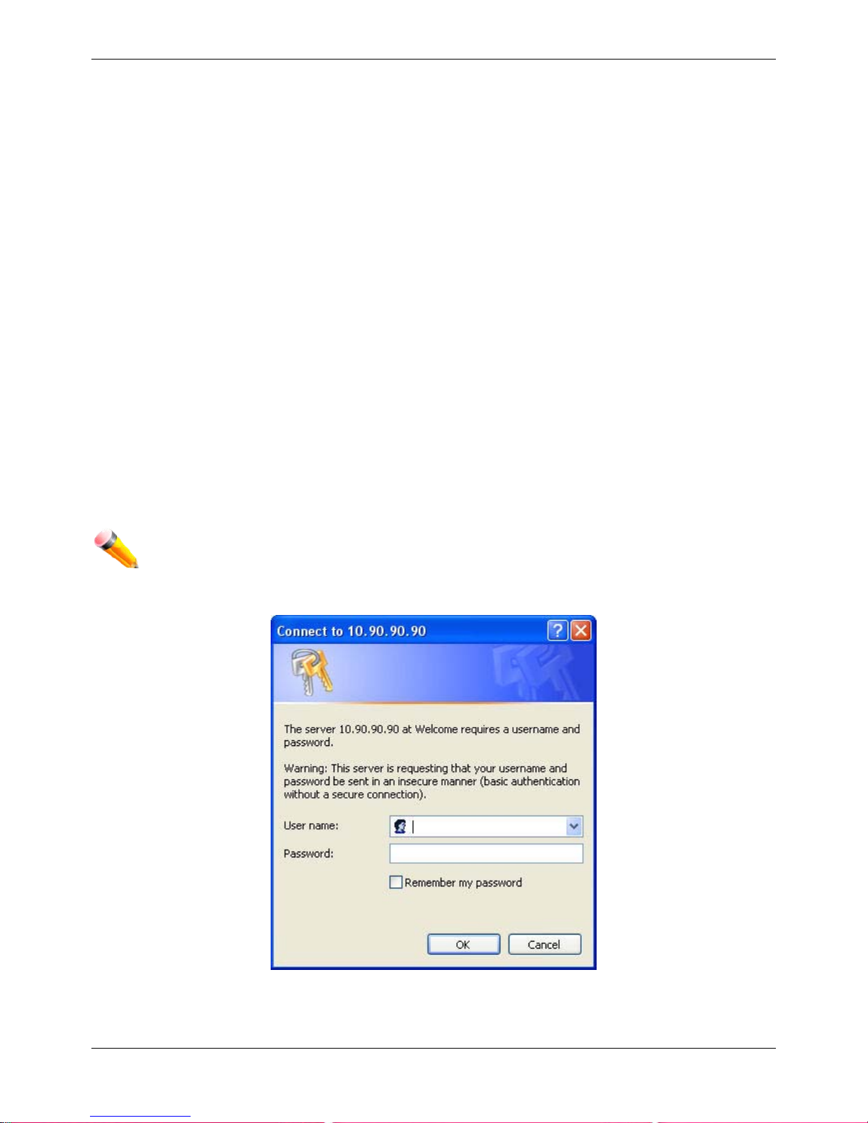
NOTE: The factory default IP address is 10.90.90.90.
This opens the management module's user authentication window, as seen below.
Figure 1-1 Enter Network Password window
Leave both the User Name field and the Password field blank and click OK. This will open the Web-based user
interface. The Switch management features available in the web-based manager are explained below.
Page 16
xStack® DGS-3620 Series Managed Switch Web UI Reference Guide
6
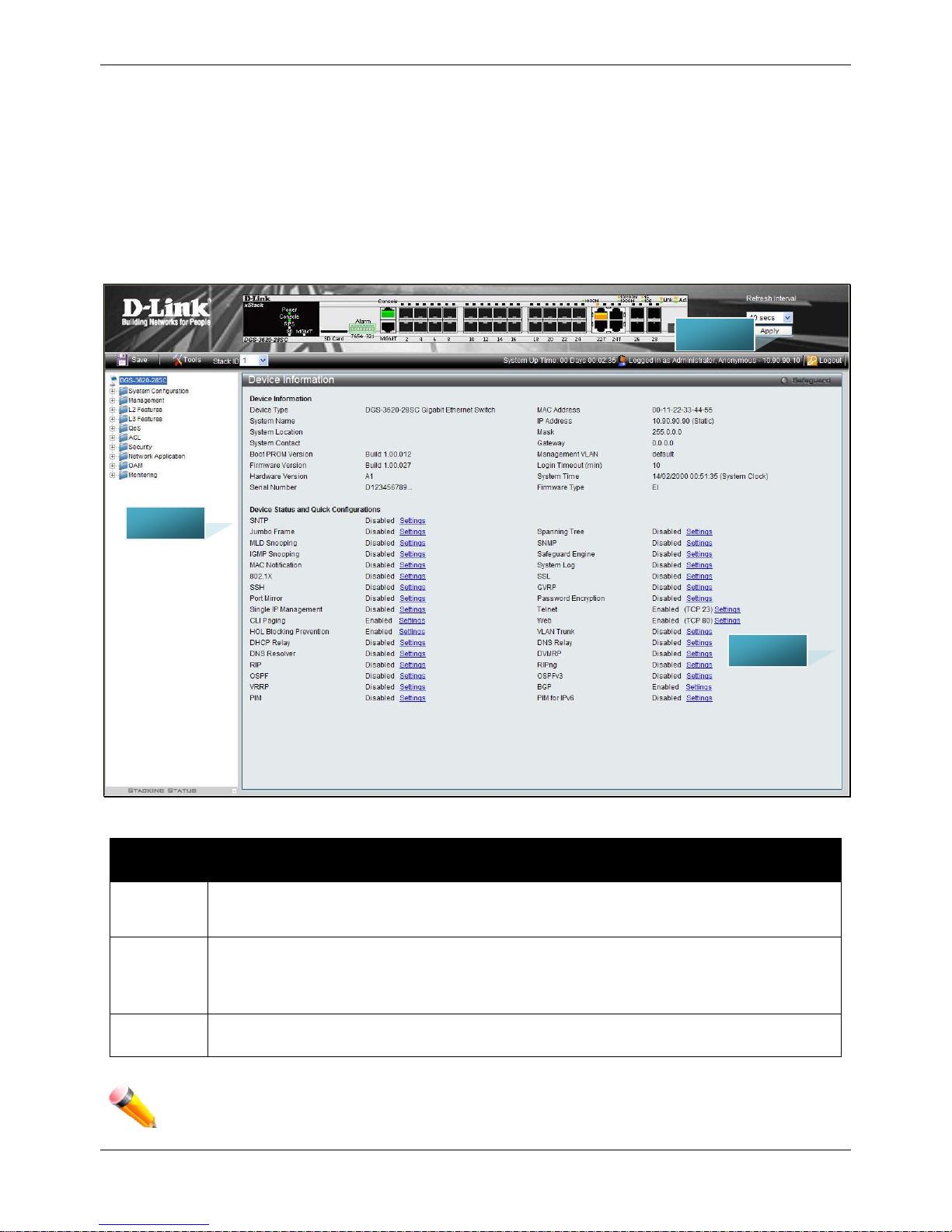
Web-based User Interface
The user interface provides access to various Switch configuration and management windows, allows you to view
performance statistics, and permits you to graphically monitor the system status.
Areas of the User Interface
The figure below shows the user interface. Three distinct areas divide the user interface, as described in the table.
Figure 1-2 Main Web-Manager page
Area
Number
Function
Area 1
Select the menu or window to display. Open folders and click the hyperlinked menu buttons
and subfolders contained within them to display menus. Click the D-Link logo to go to the D-
Link website.
Area 2
Presents a graphical near real-time image of the front panel of the Switch. This area displays
the Switch's ports, console and management port, showing port activity.
Some management functions, including save, reboot, download and upload are accessible
here.
Area 3
Presents switch information based on user selection and the entry of configuration data.
NOTE: Any changes made to the Switch configuration during the current session must be saved in the
Save Configuration / Log window or use the command line interface (CLI) command save.
ARE A 2
ARE A 1
ARE A 3
Page 17

xStack® DGS-3620 Series Managed Switch Web UI Reference Guide
7
Web Pages
When connecting to the management mode of the Switch with a web browser, a login screen is displayed. Enter a
user name and password to access the Switch's management mode.
Below is a list of the main folders available in the Web interface:
System Configuration - In this section the user will be able to configure features regarding the Switch’s
configuration.
Management - In this section the user will be able to configure features regarding the Switch’s management.
L2 Features - In this section the user will be able to configure features regarding the Layer 2 functionality of the
Switch.
L3 Features - In this section the user will be able to configure features regarding the Layer 3 functionality of the
Switch.
QoS - In this section the user will be able to configure features regarding the Quality of Service functionality of the
Switch.
ACL - In this section the user will be able to configure features regarding the Access Control List functionality of the
Switch.
Security - In this section the user will be able to configure features regarding the Switch’s security.
Network Application - In this section the user will be able to configure features regarding network applications
handled by the Switch.
OAM - In this section the user will be able to configure features regarding the Switch’s operations, administration
and maintenance (OAM).
Monitoring - In this section the user will be able to monitor the Switch’s configuration and statistics.
NOTE: Be sure to configure the user name and password in the User Accounts menu before
connecting the Switch to the greater network.
Page 18

xStack® DGS-3620 Series Managed Switch Web UI Reference Guide
8
Chapter 2 System Configuration
Device Information
System Information Settings
Port Configuration
PoE
Serial Port Settings
Warning Temperature Settings
System Log configuration
Time Range Settings
Port Group Settings
Time Settings
User Accounts Settings
Command Logging Settings
Stacking
Device Information
This window contains the main settings for all the major functions for the Switch. It appears automatically when you
log on to the Switch. To return to the Device Information window after viewing other windows, click the DGS-3620
Series link.
The Device Information window shows the Switch’s MAC Address (assigned by the factory and unchangeable), the
Boot PROM Version, Firmware Version, Hardware Version, and many other important types of information. This is
helpful to keep track of PROM and firmware updates and to obtain the Switch’s MAC address for entry into another
network device’s address table, if necessary. In addition, this window displays the status of functions on the Switch
to quickly assess their current global status.
Many functions are hyper-linked for easy access to enable quick configuration from this window.
Page 19
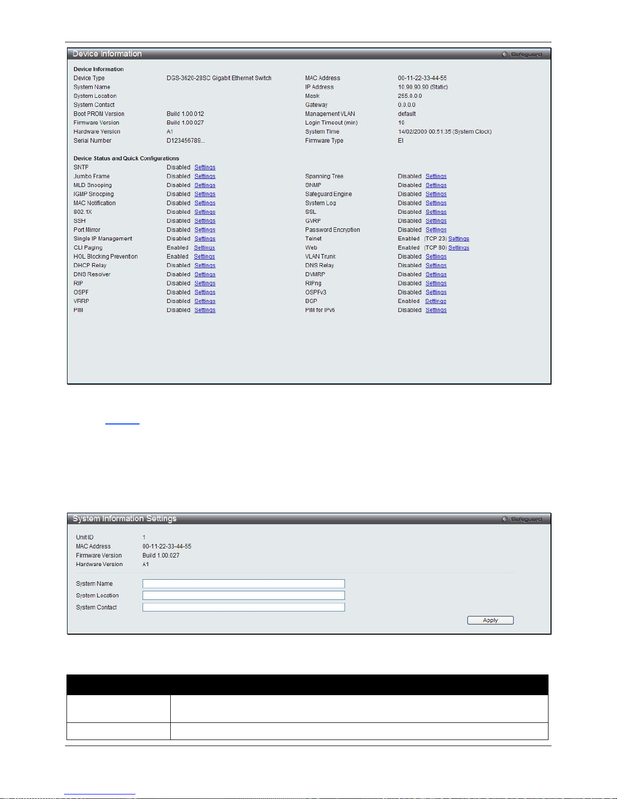
xStack® DGS-3620 Series Managed Switch Web UI Reference Guide
9
Figure 2-1 Device Information windo w
Click the
Settings
link to navigate to the appropriate feature page for configuration.
System Information Settings
The user can enter a System Name, System Location, and System Contact to aid in defining the Switch.
To view the following window, click System Configuration > System Information Settings, as show below:
Figure 2-2 System Information Settings window
The fields that can be configured are described below:
Parameter Description
System Name
Enter a system name for the Switch, if so desired. This name will identify it in the
Switch network.
System Location
Enter the location of the Switch, if so desired.
Page 20
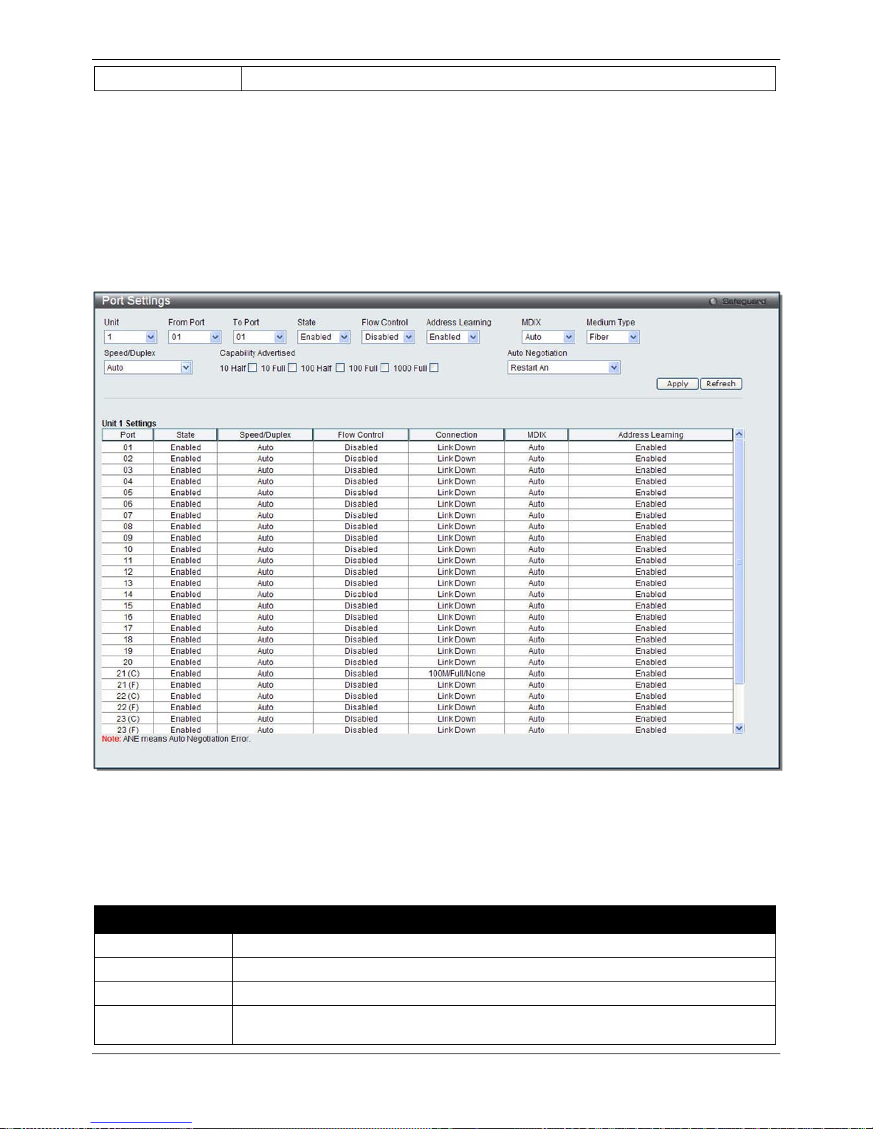
xStack® DGS-3620 Series Managed Switch Web UI Reference Guide
10
System Contact
Enter a contact name for the Switch, if so desired.
Click the Apply button to implement changes made.
Port Configuration
Port Settings
This page used to configure the details of the switch ports.
To view the following window, click System Configuration > Port Configuration > Port Settings, as show below:
Figure 2-3 Port Settings window
To configure switch ports:
1. Choose the port or sequential range of ports using the From Port and To Port drop-down menus.
2. Use the remaining drop-down menus to configure the parameters described below:
The fields that can be configured are described below:
Parameter Description
Unit
Select the unit you wish to configure.
From Port / To Port
Select the appropriate port range used for the configuration here.
State
Toggle the State field to either enable or disable a given port or group of ports.
Speed/Duplex Use the drop-down menu to select the speed in Auto, 10M Half, 10M Full, 100M Half,
100M Full, 1000M Full_Master and 1000M Full_Slave. Auto denotes auto-negotiation
Page 21

xStack® DGS-3620 Series Managed Switch Web UI Reference Guide
11
among 10, 100 and 1000 Mbps devices, in full- or half-duplex (except 1000 Mbps which
is always full duplex). The Auto setting allows the port to automatically determine the
fastest settings the device the port is connected to can handle, and then to use those
settings. The other options are 10M Half, 10M Full, 100M Half, 100M Full, 1000M
Full_Master, 1000M Full_Slave, and 1000M Full. There is no automatic adjustment of
port settings with any option other than Auto.
The Switch allows the user to configure two types of gigabit connections; 1000M
Full_Master, and 1000M Full_Slave which refer to connections running a 1000BASE-T
cable for connection between the Switch port and other device capable of a gigabit
connection. The master setting (1000M Full_Master) will allow the port to advertise
capabilities related to duplex, speed and physical layer type. The master setting will also
determine the master and slave relationship between the two connected physical layers.
This relationship is necessary for establishing the timing control between the two
physical layers. The timing control is set on a master physical layer by a local source.
The slave setting (1000M Full_Slave) uses loop timing, where the timing comes from a
data stream received from the master. If one connection is set for 1000M Full_Master,
the other side of the connection must be set for 1000M Full_Slave. Any other
configuration will result in a link down status for both ports.
Capability
Advertised
When the Speed/Duplex is set to Auto, these capabilities are advertised during auto
negotiation.
Flow Control
Displays the flow control scheme used for the various port configurations. Ports
configured for full-duplex use 802.3x flow control, half-duplex ports use backpressure
flow control, and Auto ports use an automatic selection of the two. The default is
Disabled.
Connection
Here the current connection speed will be displayed.
MDIX Auto - Select auto for auto sensing of the optimal type of cabling.
Normal - Select normal for normal cabling. If set to normal state, the port is in MDI mode
and can be connected to a PC NIC using a straight-through cable or a port (in MDI
mode) on another switch through a cross-over cable.
Cross - Select cross for cross cabling. If set to cross state, the port is in MDIX mode, and
can be connected to a port (in MDI mode) on another switch through a straight cable.
Address Learning Enable or disable MAC address learning for the selected ports. When Enabled,
destination and source MAC addresses are automatically listed in the forwarding table.
When address learning is Disabled, MAC addresses must be manually entered into the
forwarding table. This is sometimes done for reasons of security or efficiency. See the
section on Forwarding/Filtering for information on entering MAC addresses into the
forwarding table. The default setting is Enabled.
Medium Type
If configuring the Combo ports, this defines the type of transport medium to be used.
Auto Negotiation
Use the drop-down menu to specify the auto-negotiation configuration.
Restart An – Select to restart the auto-negotiation process
Remote Fault Advertisedt - The remote fault advertisement option will be configured.
Click the Apply button to implement changes made.
Click the Refresh button to refresh the display section of this page.
Port Description Settings
The Switch supports a port description feature where the user may name various ports.
To view the following window, click System Configuration > Port Configuration > Port Description Settings, as
show below:
Page 22
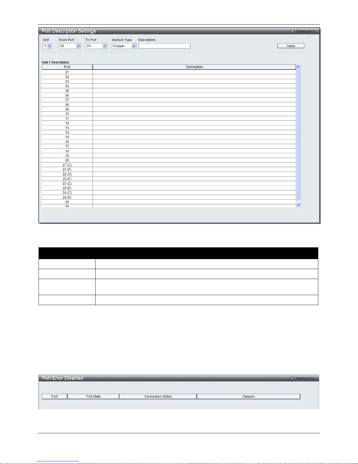
xStack® DGS-3620 Series Managed Switch Web UI Reference Guide
12
Figure 2-4 Port Description Settings window
The fields that can be configured are described below:
Parameter Description
Unit
Select the unit you wish to configure.
From Port / To Port
Select the appropriate port range used for the configuration here.
Medium Type
Specify the medium type for the selected ports. If configuring the Combo ports, the
Medium Type defines the type of transport medium to be used, whether Copper or Fiber.
Description
Users may then enter a description for the chosen port(s).
Click the Apply button to implement changes made.
Port Error Disabled
The following window displays the information about ports that have been disconnected by the Switch when a
packet storm occurs or a loop was detected.
To view the following window, click System Configuration > Port Configuration > Port Error Disabled, as show
below:
Figure 2-5 Port Error Disabled
Page 23
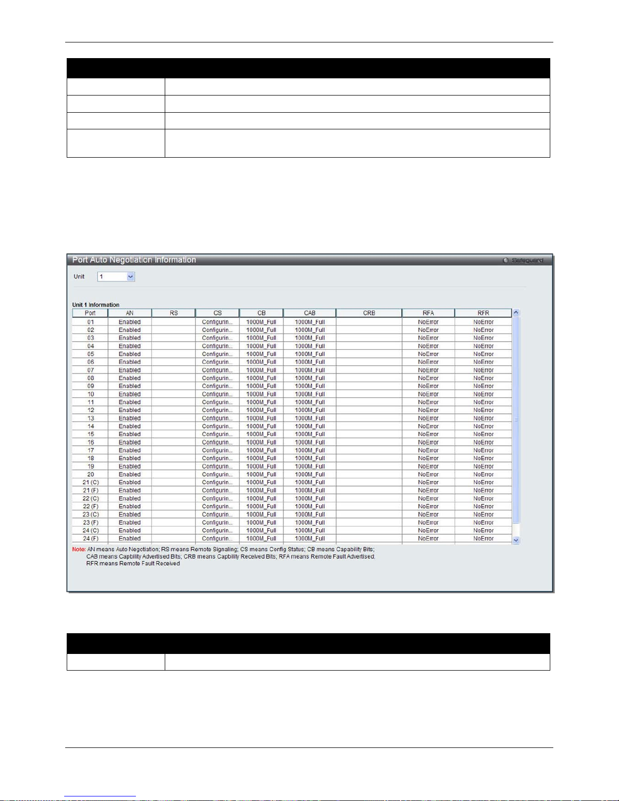
xStack® DGS-3620 Series Managed Switch Web UI Reference Guide
13
The fields that can be displayed are described below:
Parameter Description
Port
Display the port that has been error disabled.
Port State
Describe the current running state of the port, whether enabled or disabled.
Connection Status
Display the uplink status of the individual ports, whether enabled or disabled.
Reason
Describe the reason why the port has been error-disabled, such as it has become a
shutdown port for storm control.
Port Auto Negotiation Information
The following window displays the detailed auto negotiation information.
To view the following window, click System Configuration > Port Configuration > Port Auto Negotiation
Information, as show below:
Figure 2-6 Port Auto Negotiation Information window
The fields that can be configured are described below:
Parameter Description
Unit
Select the unit you wish to display.
Page 24
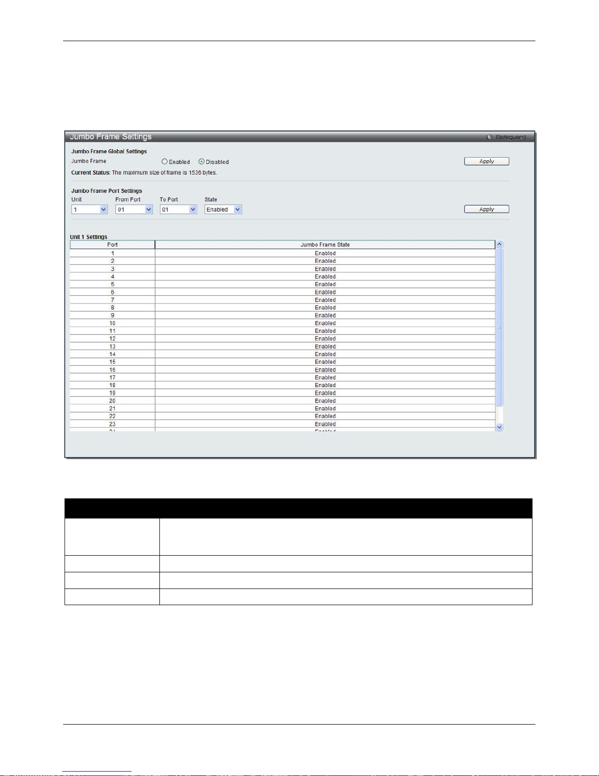
xStack® DGS-3620 Series Managed Switch Web UI Reference Guide
14
Jumbo Frame Settings
The Switch supports jumbo frames. Jumbo frames are Ethernet frames with more than 1,518 bytes of payload. The
Switch supports jumbo frames with a maximum frame size of up to 13312 bytes.
To view the following window, click System Configuration > Port Configuration > Jumbo Frame Settin g s, as
show below:
Figure 2-7 Jumbo Frame Settings window
The fields that can be configured are described below:
Parameter Description
Jumbo Frame
Use the radio buttons to enable or disable the Jumbo Frame function on the Switch. The
default is Disabled. When disabled, the maximum frame size is 1536 bytes. When
enabled, the maximum frame size is 13312 bytes.
Unit
Select the unit you wish to configure.
From Port / To Port
Select the appropriate port range used for the configuration here.
State
Use the drop-down menu to enable the Jumbo Frame for the port.
Click the Apply button to implement changes made.
PoE
The DGS-3620-28PC and DGS-3620-52P switches support Power over Ethernet (PoE) as defined by the IEEE
802.3af and 802.3at. All ports can support PoE up to 30W. Ports 1-24 can supply about 48 VDC power to Powered
Devices (PDs) over Category 5 or Category 3 UTP Ethernet cables. The Switch follows the standard PSE (Power
Sourcing Equipment) pinout Alternative A, whereby power is sent out over pins 1, 2, 3 and 6. The Switches work
with all D-Link 802.3af capable devices.
Page 25
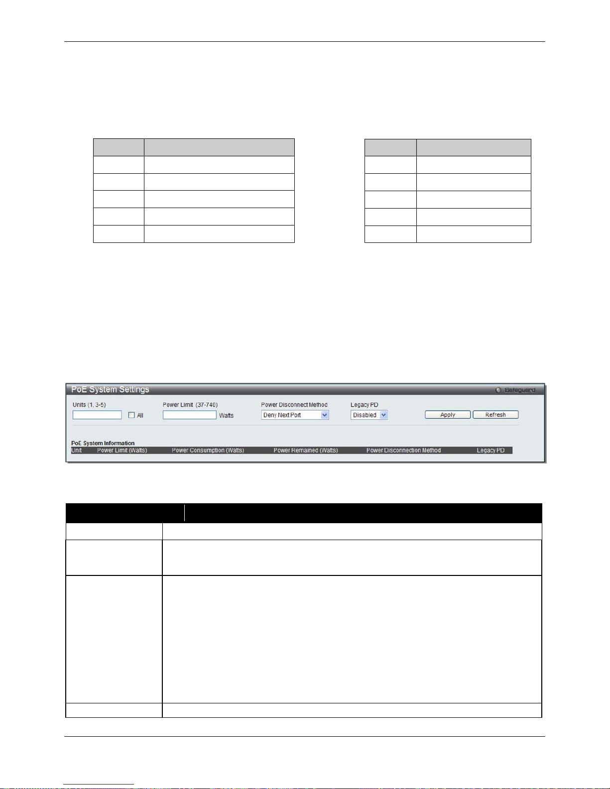
xStack® DGS-3620 Series Managed Switch Web UI Reference Guide
15
The Switch includes the following PoE features:
• Auto-discovery recognizes the connection of a PD (Powered Device) and automatically sends power to it.
• The Auto-disable feature occurs under two conditions: firstly, if the total power consumption exceeds the
system power limit; and secondly, if the per port power consumption exceeds the per port power limit.
• Active circuit protection automatically disables the port if there is a short. Other ports will remain active.
Based on 802.3af/at PDs receive power according to the following classification:
Class Maximum power available to PD
0 12.95W
1 3.84W
2 6.49W
3 12.95W
4 29.5W
To configure the PoE features on the Switch, click System Configuration > PoE. The PoE System Settings
window is used to assign a power limit and power disconnect method for the whole PoE system. To configure the
Power Limit for the PoE system, enter a value between 1W and 370W for the Switch in the Power Limit field.
When the total consumed power exceeds the power limit, the PoE controller (located in the PSE) disconnects the
power to prevent overloading the power supply.
PoE System Settings
To view the following window, click System Configuration > PoE > PoE System Settings, as show below:
Figure 2-8 PoE System Settings window
The following parameters can be configured:
Parameter Description
Unit
Select the unit you wish to configure. Tick the All check box to select all units.
Power Limit (37-
740)
Sets the limit of power to be used from the Switch’s power source to PoE ports. The user
may configure a Power Limit between 1 and 740W for the DGS-3620-28PC and DGS-
3620-52P. The default setting is 740W.
Power Disconnect
Method
The PoE controller uses either Deny Next Port or Deny Low Priority Port to offset the
power limit being exceeded and keeps the Switch’s power at a usable level. Use the drop
down menu to select a Power Disconnect Method. The default Power Disconnect
Method is Deny Next Port. Both Power Disconnection Methods are described below:
Deny Next Port – After the power limit has been exceeded, the next port attempting to
power up is denied, regardless of its priority. If Power Disconnection Method is set to
Deny Next Port, the system cannot utilize out of its maximum power capacity. The
maximum unused watt is 19W.
Deny Low Priority Port – After the power limit has been exceeded, the next port
attempting to power up causes the port with the lowest priority to shut down so as to
allow the high-priority and critical priority ports to power up.
Legacy PD
Use the drop-down menu to enable or disable detecting legacy PDs signal.
Click Apply to implement changes made.
PSE provides power according to the following classification:
Class Max power used by PSE
0 16.2W
1 4.2W
2 7.4W
3 16.2W
User define 31.2W
Page 26
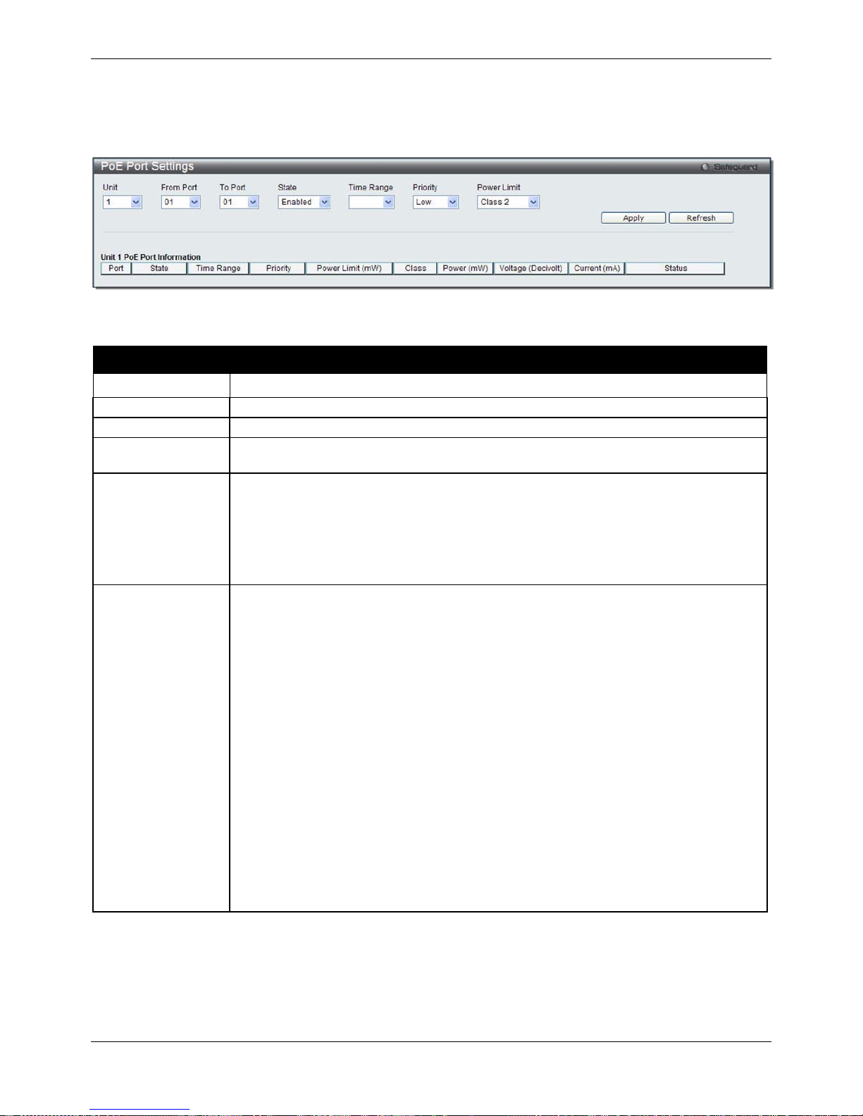
xStack® DGS-3620 Series Managed Switch Web UI Reference Guide
16
PoE Port Settings
To view the following window, click System Configuration > PoE > PoE Port Settings, as show below:
Figure 2-9 PoE Port Settings window
The following parameters can be configured:
Parameter Description
Unit
Select the unit you wish to configure.
From Port / To Port
Select a range of ports from the drop-down menus to be enabled or disabled for PoE.
State
Use the drop-down menu to enable or disable ports for PoE.
Time Range
Select a range of the time to the port set as POE. If Time Range is configured, the power
can only be supplied during the specified period of time.
Priority
Use the drop-down menu to select the priority of the PoE ports. Port priority determines
the priority which the system attempts to supply the power to the ports. There are three
levels of priority that can be selected, Critical, High, and Low. When multiple ports
happen to have the same level of priority, the port ID will be used to determine the
priority. The lower port ID has higher priority. The setting of priority will affect the order of
supplying power. Whether the disconnect method is set to deny low priority port, the
priority of each port will be used by the system to manage the supply of power to ports.
Power Limit
This function is used to configure the per-port power limit. If a port exceeds its power
limit, it will shut down.
Based on 802.3af/802.3at, there are different PD classes and power consumption
ranges;
Class 0 – 0.44~12.95W
Class 1 – 0.44~3.84W
Class 2 – 3.84~6.49W
Class 3 – 6.49~12.95W
Class 4 – 29.5W
The following is the power limit applied to the port for these five classes. For each class,
the power limit is a little more than the power consumption range for that class. This
takes into account any power loss on the cable. Thus, the following are the typical
values;
Class 0 – 16200mW
Class 1 – 4200mW
Class 2 – 7400mW
Class 3 – 16200mW
User Define – 35000mW
Click Apply to implement changes made. The port status of all PoE configured ports is displayed in the table in the
bottom half of the screen shown above.
Page 27
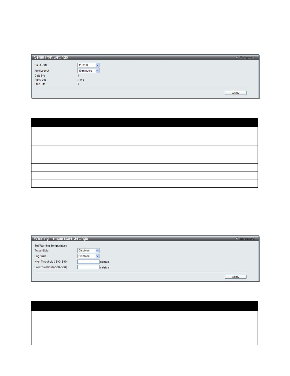
xStack® DGS-3620 Series Managed Switch Web UI Reference Guide
17
Serial Port Settings
This window allows the user to adjust the Baud Rate and the Auto Logout values.
To view the following window, click System Configuration > Serial Port Settings, as show below:
Figure 2-10 Serial Port Settings window
The fields that can be configured are described below:
Parameter Description
Baud Rate
Specify the baud rate for the serial port on the Switch. There are four possible baud rates to
choose from, 9600, 19200, 38400 and 115200. For a connection to the Switch using the
console port, the baud rate must be set to 115200, which is the default setting.
Auto Logout
Select the logout time used for the console interface. This automatically logs the user out
after an idle period of time, as defined. Choose from the following options: 2, 5, 10, 15
minutes or Never. The default setting is 10 minutes.
Data Bits
Display the data bits used for the serial port connection.
Parity Bits
Display the parity bits used for the serial port connection.
Stop Bits
Display the stop bits used for the serial port connection.
Click the Apply button to implement changes made.
Warning Temperature Settings
This window allows the user to configure the system warning temperature parameters.
To view the following window, click System Configuration > Warning Temperature Settings, as show below:
Figure 2-11 Warning Temperature Settings window
The fields that can be configured are described below:
Parameter Description
Traps State
Use the drop-down menu to enable or disable the traps state option of the warning
temperature setting.
Log State
Use the drop-down menu to enable or disable the log state option of the warning
temperature setting.
High Threshold
Enter the high threshold value of the warning temperature setting.
Page 28
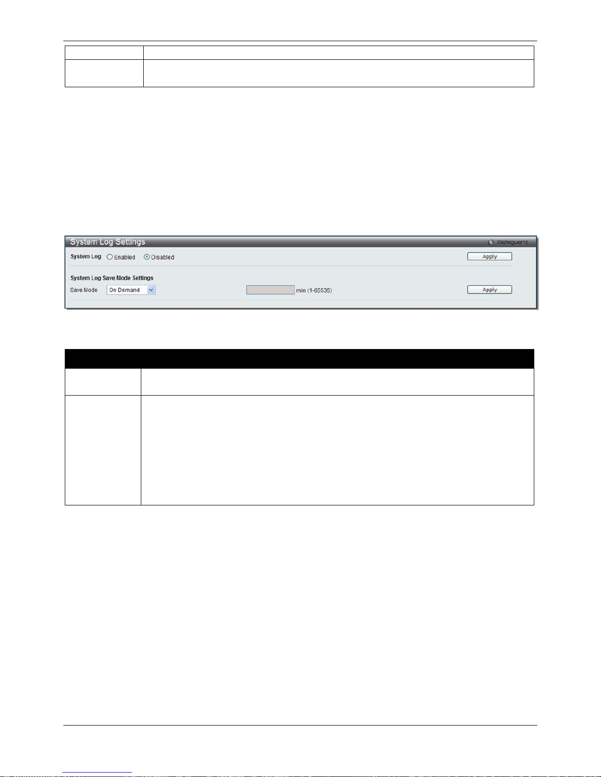
xStack® DGS-3620 Series Managed Switch Web UI Reference Guide
18
(-500-500)
Low Threshold
(-500-500)
Enter the low threshold value of the warning temperature setting.
Click the Apply button to implement changes made.
System Log configuration
System Log Settings
The Switch allows users to choose a method for which to save the switch log to the flash memory of the Switch.
To view the following window, click System Configuration > System Log Configuration > System Log Settings,
as show below:
Figure 2-12 System Log Settings window
The fields that can be configured are described below:
Parameter Description
System Log Use the radio buttons to enable or disable the system log settings. Click the Apply button to
accept the changes made.
Save Mode
Use the drop-down menu to choose the method for saving the switch log to the flash memory.
The user has three options:
On Demand – Users who choose this method will only save log files when they manually tell
the Switch to do so, either using the Save Log link in the Save folder.
Time Interval – Users who choose this method can configure a time interval by which the
Switch will save the log files, in the box adjacent to this configuration field. The user may set
a time between 1 and 65535 minutes.
Log Trigger – Users who choose this method will have log files saved to the Switch every
time a log event occurs on the Switch.
Click the Apply button to implement changes made.
System Log Server Settings
The Switch can send System log messages to up to four designated servers using the System Log Server.
To view the following window, click System Configuration > System Log Configuration > System Log Server
Settings, as show below:
Page 29
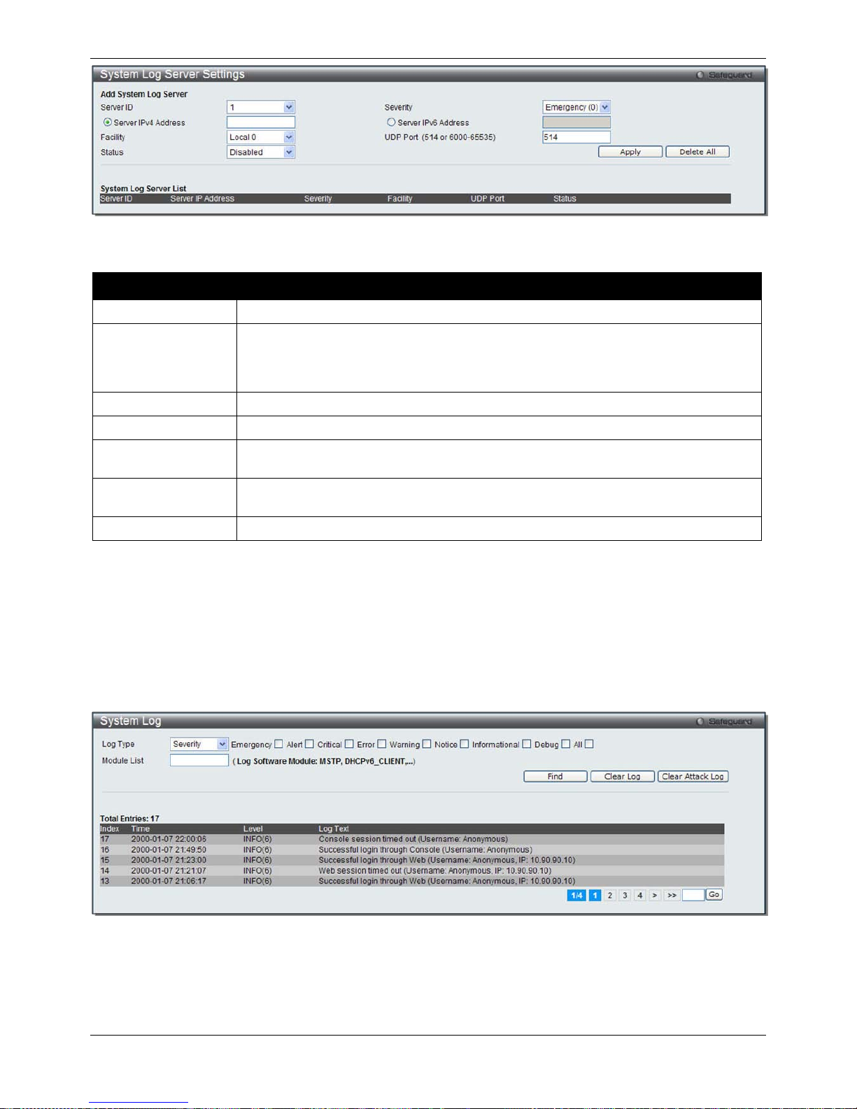
xStack® DGS-3620 Series Managed Switch Web UI Reference Guide
19
Figure 2-13 System Log Server Settings
The fields that can be configured are described below:
Parameter Description
Server ID
Syslog server settings index (1 to 4).
Severity
Use the drop-down menu to select the higher level of messages that will be sent. All
messages which level is higher than selecting level will be sent. The options are
Emergency(0), Alert(1), Critical(2), Error(3), Warning(4), Notice(5), Informational(6) and
Debug(7).
Server IPv4 Address
The IPv4 address of the Syslog server.
Server IPv6 Address
The IPv6 address of the Syslog server.
Facility Use the drop-down menu to select Local 0, Local 1, Local 2, Local 3, Local 4, Local 5,
Local 6, or Local 7.
UDP Port
(514 or 6000-65535)
Type the UDP port number used for sending Syslog messages. The default is 514.
Status
Choose Enabled or Disabled to activate or deactivate.
Click the Apply button to accept the changes made.
Click the Delet e All button to remove all servers configured.
System Log
Users can view and delete the local history log as compiled by the Switch's management agent.
To view the following window, click System Configuration > System Log Configuration > System Log, as show
below:
Figure 2-14 System Log window
The Switch can record event information in its own log. Click Go to go to the next page of the System Log window.
The fields that can be configured or displayed are described below:
Page 30
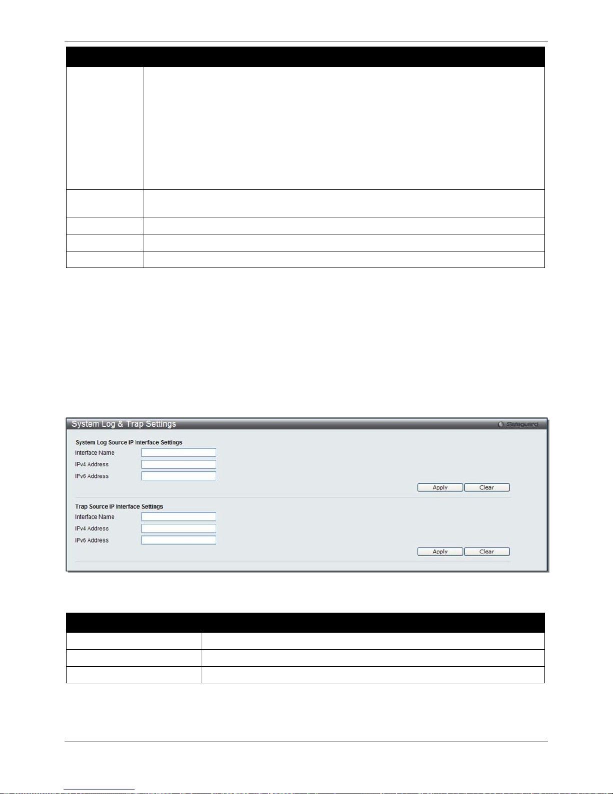
xStack® DGS-3620 Series Managed Switch Web UI Reference Guide
20
Parameter Description
Log Type
In the drop-down menu the user can select the log type that will be displayed.
Severity - When selecting Severity from the drop-down menu, a secondary tick must be
made. Secondary ticks are Emergency, Alert, Critical, Error, Warning, Notice,
Informational and Debug. To view all information in the log, simply tick the All check box.
Enter the module name to search for the specific module.
Module List - When selecting Module List, the module name must be manually entered.
Available modules are CFM_EXT, DHCPv6_CLIENT, DHCPv6_RELAY, DHCPv6_SERVER,
ERPS, ERROR_LOG MSTP, OSPFV2 and VRRP.
Attack Log - When selecting Attack Log all attacks will be listed. Select a unit from the drop-
down menu to display the result of the unit.
Index
A counter incremented whenever an entry to the Switch's history log is made. The table
displays the last entry (highest sequence number) first.
Time
Display the time in days, hours, minutes, and seconds since the Switch was last restarted.
Level
Display the level of the log entry.
Log Text
Display text describing the event that triggered the history log entry.
Click the Find button to display the log in the display section according to the selection made.
Click the Clear Log button to clear the entries from the log in the display section.
Click the Clear Attack Log button to clear the entries from the attack log in the display section.
Enter a page number and click the Go button to navigate to a specific page when multiple pages exist.
System Log & Trap Settings
The Switch allows users to configure the system log source IP interface addresses here.
To view the following window, click System Configuration > System Log Configuration > System Log & Trap
Settings, as show below:
Figure 2-15 System Log & Trap Settings window
The fields that can be configured are described below:
Parameter Description
Interface Name
Enter the IP interface name used.
IPv4 Address
Enter the IPv4 address used.
IPv6 Address
Enter the IPv6 address used.
Click the Apply button to accept the changes made.
Click the Clear button to clear all the information entered in the fields.
Page 31

xStack® DGS-3620 Series Managed Switch Web UI Reference Guide
21
System Severity Settings
The Switch can be configured to allow alerts be logged or sent as a trap to an SNMP agent. The level at which the
alert triggers either a log entry or a trap message can be set as well. Use the System Severity Settings window to
set the criteria for alerts. The current settings are displayed below the System Severity Table.
To view the following window, click System Configuration > System Log Configuration > System Severity
Settings, as show below:
Figure 2-16 System Severity Settings wind o w
The fields that can be configured are described below:
Parameter Description
System Severity Choose how the alerts are used from the drop-down menu. Select Log to send the alert
of the Severity Type configured to the Switch’s log for analysis. Choose Trap to send it
to an SNMP agent for analysis, or select All to send the chosen alert type to an SNMP
agent and the Switch’s log for analysis.
Severity Level
This drop-down menu allows you to select the level of messages that will be sent. The
options are Emergency (0), Alert (1), Critical (2), Error (3), Warning (4), Notice (5),
Information (6) and Debug (7).
Click the Apply button to accept the changes made.
Time Range Settings
Time range is a time period that the respective function will take an effect on, such as ACL. For example, the
administrator can configure the time-based ACL to allow users to surf the Internet on every Saturday and every
Sunday, meanwhile to deny users to surf the Internet on weekdays.
The user may enter up to 64 time range entries on the Switch.
To view the following window, click System Configuration > Time Range Settings, as show below:
Figure 2-17 Time Range Settings window
The fields that can be configured are described below:
Parameter Description
Range Name
Enter a name of no more than 32 alphanumeric characters that will be used to identify
this time range on the Switch. This range name will be used in the Access Profile table
to identify the access profile and associated rule to be enabled during this time range.
Page 32

xStack® DGS-3620 Series Managed Switch Web UI Reference Guide
22
Hours (HH MM SS)
This parameter is used to set the time in the day that this time range is to be enabled
using the following parameters:
Start Time - Use this parameter to identify the starting time of the time range, in hours,
minutes and seconds, based on the 24-hour time system.
End Time - Use this parameter to identify the ending time of the time range, in hours,
minutes and seconds, based on the 24-hour time system.
Weekdays
Use the check boxes to select the corresponding days of the week that this time range
is to be enabled. Tick the Select All Days check box to configure this time range for
every day of the week.
Click the Apply button to accept the changes made. Current configured entries will be displayed in the Time
Range Information table in the bottom half of the window shown above.
Port Group Settings
This window is used to create port groups, and add or delete ports from the port groups.
To view the following window, click System Configuration > Port Group Settings, as show below:
Figure 2-18 Port Group Settings window
The fields that can be configured are described below:
Parameter
Description
Group Name
Enter the name of a port group.
Group ID (1-64)
Enter the ID of a port group
Port List
Enter a port or list of ports. Tick the All check box to apply to all ports.
Action
Use the drop-down menu to select Create Port Group, Add Ports or Delete Ports.
Click the Apply button to accept the changes made.
Click the Delete button to remove the specific entry.
Time Settings
Users can configure the time settings for the Switch.
To view the following window, click System Configuration > Time Settings, as show below:
Figure 2-19 Time Settings window
The fields that can be configured are described below:
Page 33

xStack® DGS-3620 Series Managed Switch Web UI Reference Guide
23
Parameter Description
Date (DD/MM/YYYY)
Enter the current day, month, and year to update the system clock.
Time (HH:MM:SS)
Enter the current time in hours, minutes, and seconds.
Click the Apply button to accept the changes made.
User Accounts Settings
The Switch allows the control of user privileges.
To view the following window, click System Configuration > User Accounts Settings, as show below:
Figure 2-20 User Accounts Settings window
To add a new user, type in a User Name and New Password and retype the same password in the Confirm New
Password field. Choose the level of privilege (Admin, Operator, Power User or User) from the Access Right dropdown menu.
Management
Admin
Operator
Power User
User
Configuration Read/Write Read/Write–
partly
Read/Write–
partly
No
Network Monitoring
Read/Write
Read/Write
Read-only
Read-only
Community Strings and Trap
Stations
Read/Write Read-only Read-only Read-only
Update Firmware and
Configuration Files
Read/Write No No No
System Utilities
Read/Write
Read-only
Read-only
Read-only
Factory Reset
Read/Write
No
No
No
User Account Management
Add/Update/Delete User Accounts
Read/Write
No
No
No
View User Accounts
Read/Write
No
No
No
The fields that can be configured are described below:
Parameter Description
User Name
Enter a new user name for the Switch.
Access Right
Specify the access right for this user.
Encryption Specifies that encryption will be applied to this account. Option to choose from are Plain
Text, and SHA-1.
Password
Enter a new password for the Switch.
Confirm Password
Re-type in a new password for the Switch.
Click the Apply button to accept the changes made.
Page 34

xStack® DGS-3620 Series Managed Switch Web UI Reference Guide
24
NOTICE: In case of lost passwords or password corruption, refer to Appendix B Password Recovery
Procedure which will guide you through the steps necessary to resolve this issue.
NOTE: User Name should be less than 16 characters. Password should be less than 16 or 35
characters.
Command Logging Settings
This window is used to enable or disable the command logging settings.
To view this window, click System Configuration > Command Logging Settings, as shown below:
Figure 2-21 Command Logging Settings window
The fields that can be configured are described below:
Parameter Description
Command Logging State
Use the radio buttons to enable or disable the function.
Click the Apply button to accept the changes made.
NOTE: When the switch is under the booting or executing downloaded configuration procedure, all
configuration commands will not be logged. When the user uses AAA authentication to logged
in, the user name should not be changed if the user has used the Enable Admin function to
replace its privilege.
Stacking
From firmware release v1.00 of this Switch, the Switch now supports switch stacking, where a set of 12 switches
can be combined to be managed by one IP address through Telnet, the GUI interface (web), the console port or
through SNMP. Each switch of this series has two stacking ports located at the rear of the device, which can be
used to connect other devices and make them stack together. After adding these stacking ports, the user may
connect these ports together using copper cables (also sold separately) in one of two possible topologies.
Duplex Chain – As shown in Figure 2-22, The Duplex Chain topology stacks switches together in a chain-link
format. Using this method, data transfer is only possible in one direction and if there is a break in the chain, then
data transfer will obviously be affected.
Duplex Ring – As shown in Figure 2-23, the Duplex Ring stacks switches in a ring or circle format where data can
be transferred in two directions. This topology is very resilient due to the fact that if there is a break in the ring, data
can still be transferred through the stacking cables between switches in the stack.
Page 35

xStack® DGS-3620 Series Managed Switch Web UI Reference Guide
25
Figure 2-22 Switches stacked in a Duplex Chain Figure 2-23 Switches stacked in a Duplex Ring
Within each of these topologies, each switch plays a role in the Switch stack. These roles can be set by the user
per individual Switch, or if desired, can be automatically determined by the Switch stack. Three possible roles exist
when stacking with the Switch.
Primary Master – The Primary Master is the leader of the stack. It will maintain normal operations, monitor
operations and the running topology of the Stack. This switch will also assign Stack Unit IDs, synchronize
configurations and transmit commands to remaining switches in the switch stack. The Primary Master can be
manually set by assigning this Switch the highest priority (a lower number denotes a higher priority) before
physically assembling the stack, or it can be determined automatically by the stack through an election process
which determines the lowest MAC address and then will assign that switch as the Primary Master, if all priorities
are the same. The Primary master are physically displayed by the seven segment LED to the far right on the front
panel of the switch where this LED will flash between its given Box ID and ‘H’.
Backup Master – The Backup Master is the backup to the Primary Master, and will take over the functions of the
Primary Master if the Primary Master fails or is removed from the Stack. It also monitors the status of neighboring
switches in the stack, will perform commands assigned to it by the Primary Master and will monitor the running
status of the Primary Master. The Backup Master can be set by the user by assigning this Switch the second
highest priority before physically assembling the stack, or it can be determined automatically by the stack through
an election process which determines the second lowest MAC address and then will assign that switch as the
Backup Master, if all priorities are the same. The Backup master are physically displayed by the seven segment
LED to the far right on the front panel of the switch where this LED will flash between its given Box ID and ‘h’.
Slave – Slave switches constitute the rest of the switch stack and although not Primary or Backup Masters, they
can be placed into these roles when these other two roles fail or are removed from the stack. Slave switches
perform operations requested by the master, monitor the status of neighbor switches in the stack and the stack
topology and adhere to the Backup Master’s commands once it becomes a Primary Master. Slave switches will do
a self-check to determine if it is to become the Backup Master if the Backup Master is promoted to the Primary
Master, or if the Backup Master fails or is removed from the switch stack. If both Primary and Backup masters fail,
or are removed from the Switch stack, it will determine if it is to become the Primary Master. These roles will be
determined, first by priority and if the priority is the same, the lowest MAC address.
Once switches have been assembled in the topology desired by the user and powered on, the stack will undergo
three processes until it reaches a functioning state.
Initialization State – This is the first state of the stack, where the runtime codes are set and initialized and the
system conducts a peripheral diagnosis to determine each individual switch is functioning properly.
Master Election State – Once the codes are loaded and initialized, the stack will undergo the Master Election
State where it will discover the type of topology used, elect a Primary Master and then a Backup Master.
Synchronization State – Once the Primary Master and the Backup Master have been established, the Primary
Master will assign Stacking Unit IDs to switches in the stack, synchronize configurations for all switches and then
transmit commands to the rest of the switches based on the users configurations of the Primary Master.
Once these steps have been completed, the switch stack will enter a normal operating mode.
Stack Switch Swapping
The stacking feature of the Switch supports “hot swapping” of switches in and out of the running stack. Users may
remove or add switches to the stack without powering down or largely affecting the transfer of data between
switches in the stack, with a few minor provisions.
When switches are “hot inserted” into the running stack, the new switch may take on the Primary Master, Backup
Master or Slave role, depending on configurations set on the newly added switch, such as configured priority or
Page 36

xStack® DGS-3620 Series Managed Switch Web UI Reference Guide
26
MAC address. Yet, if adding two stacks together that have both previously undergone the election process, and
therefore both have a Primary Master and a Backup master, a new Primary Master will be elected from one of the
already existing Primary Masters, based on priority or MAC address. This Primary Master will take over all of the
Primary Master’s roles for all new switches that were hot inserted. This process is done using discovery packets
that circulate through the switch stack every 1.5 seconds until the discovery process has been completed.
The “hot remove” action means removing a device from the stack while the stack is still running. The hot removal is
detected by the stack when it fails to receive heartbeat packets during its specified interval from a device, or when
one of the stacking ports links is down. Once the device has been removed, the remaining switches will update
their stacking topology database to reflect the change. Any one of the three roles, Primary Master, Backup Master
or Slave, may be removed from the stack, yet different processes occur for each specific device removal.
If a Slave device has been removed, the Primary Master will inform other switches of the hot remove of this device
through the use of unit leave messages. Switches in the stack will clear the configurations of the unit removed, and
dynamically learned databases, such as ARP, will be cleared as well.
If the Backup Master has been hot removed, a new Backup Master will be chosen through the election process
previously described. Switches in the stack will clear the configurations of the unit removed, and dynamically
learned databases, such as ARP, will be cleared as well. Then the Backup Master will begin backing up the
Primary Master when the database synchronization has been completed by the stack.
If the Primary Master is removed, the Backup Master will assume the Primary Master’s role and a new Backup
Master will be chosen using the election process. Switches in the stack will clear the configurations of the unit
removed, and dynamically learned databases, such as ARP, will be cleared as well. The new Primary Master will
inherit the MAC and IP address of the previous Primary Master to avoid conflict within the stack and the network
itself.
If both the Primary Master and the Backup Master are removed, the election process is immediately processed and
a new Primary Master and Backup Master is determined. Switches in the stack will clear the configurations of the
units removed, and dynamically learned databases, such as ARP, will be cleared as well. Static switch
configurations still remain in the database of the remaining switches in the stack and those functions will not be
affected.
NOTE: If there is a Box ID conflict when the stack is in the discovery phase, the device will enter
a special standalone topology mode. Users can only get device information, configure
Box IDs, save and reboot. All stacking ports will be disabled and an error message will be
produced on the local console port of each device in the stack. Users must reconfigure
Box IDs and reboot the stack.
Stacking Device Table
This window is used to display the current devices in the Switch Stack.
To view this window, click System Configuration > Stacking > Stacking Device, as shown below:
Figure 2-24 Stacking Device Table wind o w
Stacking Mode Settings
To begin the stacking process, users must first enable this device for stacking by using the Stacking Mode Settings
window.
To view this window, click System Configuration > Stacking > Stacking Mode Settings, as shown below:
Page 37

xStack® DGS-3620 Series Managed Switch Web UI Reference Guide
27
Figure 2-25 Stacking Mode Settings window
The fields that can be configured or viewed are described below:
Parameter Description
Stacking Mode
The stacking mode is disabled by default.
Force Master
Role
Use the radio buttons to enable or disable the function. It is used to ensure the master role
is unchanged when adding a new device to the current stacking topology. If the Enabled
radio button is selected, the master’s priority will become zero after the stacking has
stabilized.
Current Box ID
The Box ID of the switch in the stack to be configured.
New Box ID
The new box ID of the selected switch in the stack that was selected in the Current Box ID
field. The user may choose any number between 1 and 12 to identify the switch in the
switch stack. Auto will automatically assign a box number to the switch in the switch stack.
Priority (1-63)
Displays the priority ID of the Switch. The lower the number, the higher the priority. The
box (switch) with the lowest priority number in the stack is the Primary Master switch. The
Primary Master switch will be used to configure applications of the switch stack.
Click the Apply button to accept the changes made.
Page 38

xStack® DGS-3620 Series Managed Switch Web UI Reference Guide
28
Chapter 3 Management
ARP
Gratuitous ARP
IPv6 Neighbor Settings
IP Interface
Management Settings
Out of Band Management Settings
Session Table
Single IP Management
SNMP Settings
Telnet Settings
Web Settings
ARP
Static ARP Settings
The Address Resolution Protocol is a TCP/IP protocol that converts IP addresses into physical addresses. This
table allows network managers to view, define, modify, and delete ARP information for specific devices. Static
entries can be defined in the ARP table. When static entries are defined, a permanent entry is entered and is used
to translate IP addresses to MAC addresses.
To view the following window, click Management > ARP > Static ARP Settings, as show below:
Figure 3-1 Static ARP Settings window
The fields that can be configured are described below:
Parameter Description
ARP Aging Time (0-65535)
The ARP entry age-out time, in minutes. The default is 20 minutes.
IP Address
The IP address of the ARP entry.
MAC Address
The MAC address of the ARP entry.
Click the Apply button, located in the Global Settings section to accept the changes made in this section.
Click the Apply button, located in the Add Static ARP Entry section to accept the changes made in this section.
Click the Delet e All button to remove all the entries listed.
Click the Edit button to re-configure the specific entry.
Click the Delete button to remove the specific entry.
Page 39

xStack® DGS-3620 Series Managed Switch Web UI Reference Guide
29
Proxy ARP Settings
The Proxy ARP (Address Resolution Protocol) feature of the Switch will allow the Switch to reply to ARP requests
destined for another device by faking its identity (IP and MAC Address) as the original ARP responder. Therefore,
the Switch can then route packets to the intended destination without configuring static routing or a default gateway.
The host, usually a layer 3 switch, will respond to packets destined for another device. For example, if hosts A and
B are on different physical networks, B will not receive ARP broadcast requests from A and therefore cannot
respond. Yet, if the physical network of A is connected by a router or layer 3 switch to B, the router or Layer 3
switch will see the ARP request from A.
This local proxy ARP function allows the Switch to respond to the proxy ARP, if the source IP and destination IP
are in the same interface.
To view the following window, click Management > ARP > Proxy ARP Settings, as show below:
Figure 3-2 Proxy ARP Settings window
Click the Edit button to re-configure the specific entry and select the proxy ARP state of the IP interface. By default,
both the Proxy ARP Stat e and Local Proxy ARP State are disabled.
ARP Table
Users can display current ARP entries on the Switch.
To view the following window, click Management > ARP > ARP Table, as show below:
Figure 3-3 ARP Table window
The fields that can be configured are described below:
Parameter Description
Interface Name
Enter or view the Interface name used.
IP Address
Enter or view the IP Address used.
MAC Address
Enter or view the MAC Address used.
Click the Find button to locate a specific entry based on the information entered.
Click the Show Static button to display only the static entries in the display table.
Click the C l e a r Al l button to remove all the entries listed in the table.
Enter a page number and click the Go button to navigate to a specific page when multiple pages exist.
Page 40

xStack® DGS-3620 Series Managed Switch Web UI Reference Guide
30
Gratuitous ARP
Gratuitous ARP Global Settings
The user can enable or disable the gratuitous ARP global settings here.
To view the following window, click Management > Gratuitous ARP > Gratuitous ARP Global Settings, as show
below:
Figure 3-4 Gratuitous ARP Global Settings Window
The fields that can be configured are described below:
Parameter Description
Send On IP Interface
Status Up
The command is used to enable/disable sending of gratuitous ARP request packet
while the IPIF interface become up. This is used to automatically announce the
interface’s IP address to other nodes. By default, the state is disabled, and only one
gratuitous ARP packet will be broadcast.
Send On Duplicate IP
Detected
The command is used to enable/disable the sending of gratuitous ARP request
packet while a duplicate IP is detected. By default, the state is disabled. For this
command, the duplicate IP detected means that the system received an ARP request
packet that is sent by an IP address that match the system’s own IP address. In this
case, the system knows that somebody out there uses an IP address that is conflict
with the system. In order to reclaim the correct host of this IP address, the system can
send out the gratuitous ARP request packets for this duplicate IP address.
Gratuitous ARP
Learning
Normally, the system will only learn the ARP reply packet or a normal ARP request
packet that asks for the MAC address that corresponds to the system’s IP address.
The command is used to enable/disable learning of ARP entry in ARP cache based
on the received gratuitous ARP packet. The gratuitous ARP packet is sent by a
source IP address that is identical to the IP that the packet is queries for. By default,
the state is Disabled status.
Click the Apply button to accept the changes made.
NOTE: With the gratuitous ARP learning, the system will not learn new entry but only do the update on
the ARP table based on the received gratuitous ARP packet.
Gratuitous ARP Settings
The user can configure the IP interface’s gratuitous ARP parameter.
To view the following window, click Management > Gratuitous ARP > Gratuitous ARP Settings, as show below:
Page 41

xStack® DGS-3620 Series Managed Switch Web UI Reference Guide
31
Figure 3-5 Gratuitous ARP Settings window
The fields that can be configured are described below:
Parameter Description
Trap
Use the drop-down menu to enable or disable the trap option. By default the trap is
disabled.
Log
Use the drop-down menu to enable or disable the logging option. By default the
event log is enabled.
Interface Name Enter the interface name of the Layer 3 interface. Select All to enable or disable
gratuitous ARP trap or log on all interfaces.
Interval Time (0-65535)
Enter the periodically send gratuitous ARP interval time in seconds. 0 means that
gratuitous ARP request will not be sent periodically. By default the interval time is 0.
Click the Apply button, located in the Gratuitous ARP Trap/Log section to accept the changes made in this
section.
Click the Apply button, located in the Gratuitous ARP Periodical Send Interval section to accept the changes
made in this section.
IPv6 Neighbor Settings
The user can configure the Switch’s IPv6 neighbor settings. The Switch’s current IPv6 neighbor settings will be
displayed in the table at the bottom of this window.
To view the following window, click Management > IPv6 Neighbor Settings, as show below:
Figure 3-6 IPv6 Neighbor Settings window
The fields that can be configured are described below:
Parameter Description
Interface Name
Enter the interface name of the IPv6 neighbor.
Neighbor IPv6 Address
Enter the neighbor IPv6 address.
Link Layer MAC Address
Enter the link layer MAC address.
Page 42

xStack® DGS-3620 Series Managed Switch Web UI Reference Guide
32
Interface Name Enter the interface name of the IPv6 neighbor. Tick the All check box to search
for all current interfaces on the Switch. Tick the Hardware check box to display all
the neighbor cache entries which were written into the hardware table.
State
Use the drop-down menu to select All, Address, Static, or Dynamic. When the
user selects address from the drop-down menu, the user will be able to enter an
IPv6 address in the space provided next to the state option.
Click the Add button to add a new entry based on the information entered.
Click the Find button to locate a specific entry based on the information entered.
Click the Clear button to clear all the information entered in the fields.
IP Interface
System IP Address Settings
The IP address may initially be set using the console interface prior to connecting to it through the Ethernet. The
Web manager will display the Switch’s current IP settings.
NOTE: The Switch’s factory default IP address is 10.90.90.90 with a subnet mask of 255.0.0.0 and a
default gateway of 0.0.0.0.
To view the following window, click Management > IP Interface > System IP Address Settings, as show below:
Figure 3-7 System IP Address Settings window
The fields that can be configured are described below:
Parameter Description
Static
Allow the entry of an IP address, subnet mask, and a default gateway for the Switch.
These fields should be of the form xxx.xxx.xxx.xxx, where each xxx is a number
(represented in decimal form) between 0 and 255. This address should be a unique
address on the network assigned for use by the network administrator.
DHCP
The Switch will send out a DHCP broadcast request when it is powered up. The
DHCP protocol allows IP addresses, network masks, and default gateways to be
assigned by a DHCP server. If this option is set, the Switch will first look for a DHCP
server to provide it with this information before using the default or previously entered
settings.
Page 43

xStack® DGS-3620 Series Managed Switch Web UI Reference Guide
33
BOOTP
The Switch will send out a BOOTP broadcast request when it is powered up. The
BOOTP protocol allows IP addresses, network masks, and default gateways to be
assigned by a central BOOTP server. If this option is set, the Switch will first look for a
BOOTP server to provide it with this information before using the default or previously
entered settings.
The following table will describe the fields that are about the System Interface.
Parameter Description
Interface Name
Display the System interface name.
Management VLAN
Name
This allows the entry of a VLAN name from which a management station will be
allowed to manage the Switch using TCP/IP (in-band via Web manager or Telnet).
Management stations that are on VLANs other than the one entered here will not be
able to manage the Switch in-band unless their IP addresses are entered in the
Trusted Host window (Security > Trusted Host). If VLANs have not yet been
configured for the Switch, the default VLAN contains all of the Switch’s ports. There
are no entries in the Trusted Host table, by default, so any management station that
can connect to the Switch can access the Switch until a management VLAN is
specified or Management Station IP addresses are assigned.
Interface Admin State
Use the drop-down menu to enable or disable the configuration on this interface. If
the state is disabled, the IP interface cannot be accessed.
IP Address
This field allows the entry of an IPv4 address to be assigned to this IP interface.
Subnet Mask
A Bitmask that determines the extent of the subnet that the Switch is on. Should be of
the form xxx.xxx.xxx.xxx, where each xxx is a number (represented in decimal)
between 0 and 255. The value should be 255.0.0.0 for a Class A network,
255.255.0.0 for a Class B network, and 255.255.255.0 for a Class C network, but
custom subnet masks are allowed.
Gateway
IP address that determines where packets with a destination address outside the
current subnet should be sent. This is usually the address of a router or a host acting
as an IP gateway. If your network is not part of an intranet, or you do not want the
Switch to be accessible outside your local network, you can leave this field
unchanged.
Click the Apply button to accept the changes made.
Interface Settings
Users can display the Switch’s current IP interface settings.
To view the following window, click Management > IP Interface > Interface Settings, as show below:
Figure 3-8 Interface Settings window
The fields that can be configured are described below:
Parameter Description
Interface Name
Enter the name of the IP interface to search for.
Click the Find button to locate a specific entry based on the information entered.
Click the Add button to add a new entry based on the information entered.
Page 44

xStack® DGS-3620 Series Managed Switch Web UI Reference Guide
34
Click the Delet e All button to remove all the entries listed.
Click the IPv4 Ed it button to edit the IPv4 settings for the specific entry.
Click the IPv6 Ed it button to edit the IPv6 settings for the specific entry.
Click the Delete button to remove the specific entry.
NOTE: To create IPv6 interfaces, the user has to create an IPv4 interface then edit it to IPv6.
Click the Add button to see the following window.
Figure 3-9 IPv4 Interface Settings window
The fields that can be configured are described below:
Parameter Description
Interface Name
Enter the name of the IP interface being created.
IPv4 Address
Enter the IPv4 address used.
Subnet Mask
Enter the IPv4 subnet mask used.
VLAN Name
Enter the VLAN Name used.
Interface Admin State
Use the drop-down menu to enable or disable the Interface Admin State.
Secondary Interface
Tick the check box to use this Interface as a Secondary Interface. When the primary
IP is not available, the VLAN will switch to the secondary interface. It will switch back
when the primary IP was recovered.
Click the Apply button to accept the changes made.
Click the <<Back button to discard the changes made and return to the previous page.
Click the IPv4 Edit button to see the following window.
Figure 3-10 IPv4 Interface Settings – Edit window
The fields that can be configured are described below:
Page 45

xStack® DGS-3620 Series Managed Switch Web UI Reference Guide
35
Parameter Description
IP MTU (512-1712)
Enter the IP Layer MTU value used. The value is between 512 and 1712. The default
value is 1500.
IP Directed Broadcast
Use the drop-down menu to enable or disable the IP directed-broadcast state of the
interface.
Get IP From
Use the drop-down menu to specify the method that this Interface uses to acquire an
IP address.
Interface Name
Enter the name of the IP interface being configured.
IPv4 Address
Enter the IPv4 address used.
Subnet Mask
Enter the IPv4 subnet mask used.
VLAN Name
Enter the VLAN Name used.
IPv4 State
Use the drop-down menu to enable or disable IPv4 State.
Interface Admin State
Use the drop-down menu to enable or disable the Interface Admin State.
Click the Apply button to accept the changes made for each individual section.
Click the <<Back button to discard the changes made and return to the previous page.
Click the IPv6 Ed it button to see the following window.
Figure 3-11 IPv6 Interface Settings window
The fields that can be configured or displayed are described below:
Parameter Description
Interface Name
Display the IPv6 interface name.
IPv6 State
Use the drop-down menu to enable or disable IPv6 State.
Interface Admin State
Use the drop-down menu to enable or disable the Interface Admin State.
IPv6 Network Address
Enter the neighbor’s global or local link address.
DHCPv6 Client
Use the drop-down menu to enable or disable DHCPv6 client.
NS Retransmit Time
(0-4294967295)
Enter the Neighbor solicitation’s retransmit timer in millisecond here. It has the same
value as the RA retransmit time in the config ipv6 nd ra command. If this field is
configured, it will duplicate the entry into the RA field.
Page 46

xStack® DGS-3620 Series Managed Switch Web UI Reference Guide
36
Automatic Link Local
Address
Use the drop-down menu to enable or disable the Automatic Link Local Address.
State
Use the drop-down menu to enable or disable router advertisement.
Life Time (0-9000)
Enter the lifetime of the router between 0 and 9000 seconds as the default router.
Reachable Time (0-
3600000)
Enter the amount of time that a node can consider a neighboring node reachable
after receiving a reachability confirmation, in milliseconds.
Retransmit Time (0-
4294967295)
Enter the amount of time between retransmissions of router advertisement message
in millisecond, and the router advertisement packet will take it to host.
Hop Limit (0-255)
Enter the default value of the hop limit field in the IPv6 header for packets sent by
hosts that receive this RA message.
Managed Flag
Use the drop-down menu to enable or disable the function. When Enabled, it
indicates that hosts receiving this RA must use a stateful address configuration
protocol to obtain an address, in addition to the addresses derived from the
stateless address configuration. Set to Disabled to stop hosts receiving the RA from
using a stateful address configuration to obtain an address.
Other Configuration
Flag
Use the drop-down menu to enable or disable the function. When Enabled, it
indicates that hosts receiving this RA must use a stateful address configuration
protocol to obtain the address configuration information. Set to Disabled to stop
hosts receiving this RA from using a stateful address configuration protocol to obtain
the address configuration information.
Min Router AdvInterval
(3-1350)
Enter the minimum time allowed between sending unsolicited multicast Router
Advertisements from the interface, in seconds. It must be no less than 3 seconds
and no greater than .75 * MaxRtrAdvInterval. The default is 0.33 *
MaxRtrAdvInterval.
Max Router AdvInterval
(4-1800)
Enter the maximum time allowed between sending unsolicited multicast Router
Advertisements from the interface, in seconds. It must be no less than 4 seconds
and no greater than 1800 seconds. The default is 600 seconds.
Click the Apply button to accept the changes made for each individual section.
Click the <<Back button to discard the changes made and return to the previous page.
Click the
View All IPv6 Address
Click the
link to view all the current IPv6 address.
View Neighbor Discover
link to view all IPv6 neighbor discover.
Click the
View All IPv6 Address link to see the following window.
Figure 3-12 IPv6 Interface Settings – View All IPv6 Address window
Click the <<Back button to return to the previous page.
Click the
View Neighbor Discover link to see the following window.
Figure 3-13 IPv6 Interface Settings – View Neighbor Discover window
Click the <<Back button to return to the previous page.
Page 47

xStack® DGS-3620 Series Managed Switch Web UI Reference Guide
37
Loopback Interface Settings
This window is used to configure loopback interfaces. A loopback interface is a logical IP interface which is always
active, until a user disables or deletes it. It is independent of the state of any physical interfaces.
To view this window, click Management > IP Interface > Loopback Interfaces Settings, as show below:
Figure 3-14 Loopback Interface Settings
The fields that can be configured are described below:
Parameter Description
Interface Name
Enter an interface name.
Click the Find button to locate a specific entry based on the information entered.
Click the View All button to display all the existing entries.
Click the Add button to create a new entry.
Click the Delet e All button to remove all the entries listed in the table.
Click the Edit button to re-configure the specific entry.
Click the Delete button to remove the specific entry.
Click the Add or Edit button to see the following window.
Figure 3-15 Loopback Interface Settings - Add/Edit window
The fields that can be configured are described below:
Parameter Description
Interface Name
The name of the loopback interface.
NOTE: The loopback ipif has the same name domain space with the regular ipif, so
its name can’t be a duplicate with the regular ipif.
IPv4 Address
Enter a 32-bit IPv4 address for the loopback interface.
Subnet Mask
Enter a subnet mask to be applied to the loopback interface.
Interface Admin State
Use the drop-down menu to enable or disable the loopback interface.
Click the Apply button to accept the changes made for each individual section.
Click the <<Back button to discard the changes made and return to the previous page.
Page 48

xStack® DGS-3620 Series Managed Switch Web UI Reference Guide
38
Management Settings
Users can stop the scrolling of multiple pages beyond the limits of the console when using the Command Line
Interface.
This window is also used to enable the DHCP auto configuration feature on the Switch. When enabled, the Switch
is instructed to receive a configuration file from a TFTP server, which will set the Switch to become a DHCP client
automatically on boot-up. To employ this method, the DHCP server must be set up to deliver the TFTP server IP
address and configuration file name information in the DHCP reply packet. The TFTP server must be up and
running and hold the necessary configuration file stored in its base directory when the request is received from the
Switch. For more information about loading a configuration file for use by a client, see the DHCP server and/or
TFTP server software instructions. The user may also consult the Upload Log File window description located in
the Tools section of this manual.
If the Switch is unable to complete the DHCP auto configuration, the previously saved configuration file present in
the Switch’s memory will be used.
This window also allows the user to implement the Switch’s built-in power saving feature. When power saving is
enabled, a port which has a link down status will be turned off to save power to the Switch. This will not affect the
port’s capabilities when the port status is link up.
Users can also configure Password Encryption on the Switch.
To view the following window, click Management > Management Settings, as show below:
Figure 3-16 Management Settings window
The fields that can be configured are described below:
Parameter Description
CLI Paging State
Command Line Interface paging stops each page at the end of the console. This
allows you to stop the scrolling of multiple pages of text beyond the limits of the
console. CLI Paging is Enabled by default. To disable it, click the Disabled radio
button.
DHCP Auto
Configuration State
Enable or disable the Switch’s DHCP auto configuration feature. When enabled, the
Switch is instructed to receive a configuration file from a TFTP server, which will set
the Switch to become a DHCP client automatically on boot-up. To employ this
method, the DHCP server must be set up to deliver the TFTP server IP address and
configuration file name information in the DHCP reply packet. The TFTP server must
be up and running and hold the necessary configuration file stored in its base
directory when the request is received from the Switch.
Power Saving State
Enable or disable the link down power saving mode of each physical port. The switch
Page 49

xStack® DGS-3620 Series Managed Switch Web UI Reference Guide
39
port will go into sleep mode when a port is not connected.
Length Detection
State
Enable or disable the length detection power saving mode on the physical ports. The
switch port will reduce the power feed for shorter cables.
Password Encryption
State
Password encryption will encrypt the password configuration in configuration files.
Password encryption is Disabled by default. To enable password encryption, click the
Enabled radio button.
Running
Configuration
Under the Password Recovery option, the running configuration can be enabled or
disable. Being enabled, will allow the user to perform a password recovery of the
running configuration.
Click the Apply button to accept the changes made.
To learn more about the D-Link Green Technologies, go to
http://green.dlink.com/ for more details.
Out of Band Management Settings
This window is used to configure the out of band management port settings.
To view the following window, click Management > Out of Band Management Settings, as show below:
Figure 3-17 Out of Band managem ent Setti ngs wind o w
The fields that can be configured are described below:
Parameter Description
IP Address
Enter the IP address of the interface.
Subnet Mask
Enter the subnet mask of the IP address.
Gateway
Enter the gateway IP address of the out-of-band management network.
Satus
Use the drop-down menu to enable or disable the interface status.
Click the Apply button to accept the changes made.
Session Table
Users can display the management sessions since the Switch was last rebooted.
To view the following window, click Management > Session Table, as show below:
Figure 3-18 Session Table window
Click the Refresh button to refresh the display table so that new entries will appear.
Page 50

xStack® DGS-3620 Series Managed Switch Web UI Reference Guide
40
Single IP Management
Simply put, D-Link Single IP Management is a concept that will stack switches together over Ethernet instead of
using stacking ports or modules. There are some advantages in implementing the “Single IP Management” feature:
1. SIM can simplify management of small workgroups or wiring closets while scaling the network to handle
increased bandwidth demand.
2. SIM can reduce the number of IP address needed in your network.
3. SIM can eliminate any specialized cables for stacking connectivity and remove the distance barriers that
typically limit your topology options when using other stacking technology.
Switches using D-Link Single IP Management (labeled here as SIM) must conform to the following rules:
• SIM is an optional feature on the Switch and can easily be enabled or disabled through the Command Line
Interface or Web Interface. SIM grouping has no effect on the normal operation of the Switch in the user’s
network.
• There are three classifications for switches using SIM. The Commander Switch (CS), which is the master
switch of the group, Member Switch (MS), which is a switch that is recognized by the CS a member of a
SIM group, and a Candidate Switch (CaS), which is a Switch that has a physical link to the SIM group but
has not been recognized by the CS as a member of the SIM group.
• A SIM group can only have one Commander Switch (CS).
• A SIM group accepts up to 32 switches (numbered 1-32), not including the Commander Switch (numbered
0).
• Members of a SIM group cannot cross a router.
• There is no limit to the number of SIM groups in the same IP subnet (broadcast domain); however a single
switch can only belong to one group.
• If multiple VLANs are configured, the SIM group will only utilize the default VLAN on any switch.
• SIM allows intermediate devices that do not support SIM. This enables the user to manage switches that
are more than one hop away from the CS.
The SIM group is a group of switches that are managed as a single entity. The Switch may take on three different
roles:
1. Commander Switch (CS) – This is a switch that has been manually configured as the controlling device
for a group, and takes on the following characteristics:
a. It has an IP Address.
b. It is not a command switch or member switch of another Single IP group.
c. It is connected to the member switches through its management VLAN.
2. Member Switch (MS) – This is a switch that has joined a single IP group and is accessible from the CS,
and it takes on the following characteristics:
a. It is not a CS or MS of another IP group.
b. It is connected to the CS through the CS management VLAN.
3. Candidate Switch (CaS) – This is a switch that is ready to join a SIM group but is not yet a member of the
SIM group. The Candidate Switch may join the SIM group of the Switch by manually configuring it to be a
MS of a SIM group. A switch configured as a CaS is not a member of a SIM group and will take on the
following characteristics:
a. It is not a CS or MS of another Single IP group.
b. It is connected to the CS through the CS management VLAN
The following rules also apply to the above roles:
• Each device begins in a Candidate state.
• CSs must change their role to CaS and then to MS, to become a MS of a SIM group. Thus, the CS cannot
directly be converted to a MS.
• The user can manually configure a CS to become a CaS.
• A MS can become a CaS by:
o Being configured as a CaS through the CS.
o If report packets from the CS to the MS time out.
Page 51

xStack® DGS-3620 Series Managed Switch Web UI Reference Guide
41
• The user can manually configure a CaS to become a CS
• The CaS can be configured through the CS to become a MS.
After configuring one switch to operate as the CS of a SIM group, additional DGS-3620 Series switches may join
the group by manually configuring the Switch to be a MS. The CS will then serve as the in band entry point for
access to the MS. The CS’s IP address will become the path to all MS’s of the group and the CS’s Administrator’s
password, and/or authentication will control access to all MS’s of the SIM group.
With SIM enabled, the applications in the CS will redirect the packet instead of executing the packets. The
applications will decode the packet from the administrator, modify some data, and then send it to the MS. After
execution, the CS may receive a response packet from the MS, which it will encode and send it back to the
administrator.
When a CaS becomes a MS, it automatically becomes a member of the first SNMP community (includes read/write
and read only) to which the CS belongs. However, if a MS has its own IP address, it can belong to SNMP
communities to which other switches in the group, including the CS, do not belong.
To better improve SIM management, the DGS-3620 Series switches have been upgraded to version 1.61 in this
release. Many improvements have been made, including:
Upgrade to v1.61
1. The Commander Switch (CS) now has the capability
to automatically rediscover member switches that
have left the SIM group, either through a reboot or
web malfunction. This feature is accomplished
through the use of Discover packets and Maintenance
packets that previously set SIM members will emit
after a reboot. Once a MS has had its MAC address
and password saved to the CS’s database, if a reboot
occurs in the MS, the CS will keep this MS
information in its database and when a MS has been
rediscovered, it will add the MS back into the SIM tree
automatically. No configuration will be necessary to
rediscover these switches.
There are some instances where pre-saved MS switches
cannot be rediscovered. For example, if the Switch is still
powered down, if it has become the member of another group,
or if it has been configured to be a Commander Switch, the
rediscovery process cannot occur.
2. The topology map now includes new features for connections that are a member of a port trunking group. It
will display the speed and number of Ethernet connections creating this port trunk group, as shown in the
adjacent picture.
3. This version will support switch upload and downloads for firmware, configuration files and log files, as
follows:
a. Firmware – The switch now supports MS firmware downloads from a TFTP server.
b. Configuration Files – This switch now supports downloading and uploading of configuration files both
to (for configuration restoration) and from (for configuration backup) MS’s, using a TFTP server.
c. Log – The Switch now supports uploading MS log files to a TFTP server.
4. The user may zoom in and zoom out when utilizing the topology window to get a better, more defined view
of the configurations.
Single IP Settings
The Switch is set as a Candidate (CaS) as the factory default configuration and Single IP Management is disabled.
To view the following window, click Management > Single IP Management > Single IP Settings, as show below:
Page 52

xStack® DGS-3620 Series Managed Switch Web UI Reference Guide
42
Figure 3-19 Single IP Settings window
The fields that can be configured are described below:
Parameter Description
SIM State Use the drop-down menu to either enable or disable the SIM state on the Switch. Disabled
will render all SIM functions on the Switch inoperable.
Role State
Use the drop-down menu to change the SIM role of the Switch. The two choices are:
Candidate – A Candidate Switch (CaS) is not the member of a SIM group but is connected
to a Commander Switch. This is the default setting for the SIM role of the Switch.
Commander – Choosing this parameter will make the Switch a Commander Switch (CS).
The user may join other switches to this Switch, over Ethernet, to be part of its SIM group.
Choosing this option will also enable the Switch to be configured for SIM.
Group Name
Enter a Group Name in this textbox. This is optional. This name is used to segment
switches into different SIM groups.
Discovery
Interval (30-90)
The user may set the discovery protocol interval, in seconds that the Switch will send out
discovery packets. Returning information to a Commander Switch will include information
about other switches connected to it. (Ex. MS, CaS). The user may set the Discovery
Interval from 30 to 90 seconds. The default value is 30 seconds.
Hold Time Count
(100-255)
This parameter may be set for the time, in seconds; the Switch will hold information sent to
it from other switches, utilizing the Discovery Interval. The user may set the hold time from
100 to 255 seconds. The default value is 100 seconds.
Click the Apply button to accept the changes made.
After enabling the Switch to be a Commander Switch (CS), the Single IP Management folder will then contain four
added links to aid the user in configuring SIM through the web, including Topology, Firmware Upgrade,
Configuration Backup/Restore and Upload Log File.
Topology
This window will be used to configure and manage the Switch within the SIM group and requires Java script to
function properly on your computer.
The Java Runtime Environment on your server should initiate and lead you to the Topology window, as seen below.
Page 53

xStack® DGS-3620 Series Managed Switch Web UI Reference Guide
43
Figure 3-20 Single IP Management window - Tree View
The Topology window holds the following information on the Data tab:
Parameter Description
Device Name
This field will display the Device Name of the switches in the SIM group configured by the
user. If no device is configured by the name, it will be given the name default and tagged
with the last six digits of the MAC Address to identify it.
Local Port
Displays the number of the physical port on the CS that the MS or CaS is connected to. The
CS will have no entry in this field.
Speed
Displays the connection speed between the CS and the MS or CaS.
Remote Port
Displays the number of the physical port on the MS or CaS to which the CS is connected.
The CS will have no entry in this field.
MAC Address
Displays the MAC Address of the corresponding Switch.
Model Name
Displays the full Model Name of the corresponding Switch.
To view the Topology View window, open the View drop-down menu in the toolbar and then click Topology, which
will open the following Topology Map. This window will refresh itself periodically (20 seconds by default).
Page 54

xStack® DGS-3620 Series Managed Switch Web UI Reference Guide
44
Figure 3-21 Topology view
This window will display how the devices within the Single IP Management Group connect to other groups and
devices. Possible icons on this window are as follows:
Icon Description Icon Description
Group
Layer 3 member switch
Layer 2 commander switch
Member switch of other group
Layer 3 commander switch
Layer 2 candidate switch
Commander switch of other group
Layer 3 candidate switch
Layer 2 member switch.
Unknown device
Non-SIM devices
In the Topology view window, the mouse plays an important role in configuration and in viewing device information.
Setting the mouse cursor over a specific device in the topology window (tool tip) will display the same information
about a specific device as the Tree view does. See the window below for an example.
Tool Tips
Page 55

xStack® DGS-3620 Series Managed Switch Web UI Reference Guide
45
Figure 3-22 Device Information Utilizing the Tool Tip
Setting the mouse cursor over a line between two devices will display the connection speed between the two
devices, as shown below.
Figure 3-23 Port Speed Utilizing the Tool Tip
Right-clicking on a device will allow the user to perform various functions, depending on the role of the Switch in
the SIM group and the icon associated with it.
Right-Click
Group Icon
Page 56

xStack® DGS-3620 Series Managed Switch Web UI Reference Guide
46
Figure 3-24 Right-Clicking a Group Icon
The following options may appear for the user to configure:
• Collapse – To collapse the group that will be represented by a single icon.
• Expand – To expand the SIM group, in detail.
• Property – To pop up a window to display the group information.
Figure 3-25 Property window
Parameter Description
Device Name
This field will display the Device Name of the switches in the SIM group configured by the
user. If no Device Name is configured by the name, it will be given the name default and
tagged with the last six digits of the MAC Address to identify it.
Module Name
Displays the full module name of the switch that was right-clicked.
MAC Address
Displays the MAC Address of the corresponding Switch.
Remote Port No
Displays the number of the physical port on the MS or CaS that the CS is connected to.
The CS will have no entry in this field.
Local Port No
Displays the number of the physical port on the CS that the MS or CaS is connected to.
The CS will have no entry in this field.
Port Speed
Displays the connection speed between the CS and the MS or CaS
Click the Close button to close the property window.
Commander Switch Icon
Figure 3-26 Right-clicking a Command er Icon
The following options may appear for the user to configure:
• Collapse – To collapse the group that will be represented by a single icon.
Page 57

xStack® DGS-3620 Series Managed Switch Web UI Reference Guide
47
• Expand – To expand the SIM group, in detail.
• Property – To pop up a window to display the group information.
Member Switch Icon
Figure 3-27 Right-clicking a Member icon
The following options may appear for the user to configure:
• Collapse – To collapse the group that will be represented by a single icon.
• Expand – To expand the SIM group, in detail.
• Remove from group – Remove a member from a group.
• Configure – Launch the web management to configure the Switch.
• Property – To pop up a window to display the device information.
Candidate Switch Icon
Figure 3-28 Right-clicking a Candidate icon
The following options may appear for the user to configure:
• Collapse – To collapse the group that will be represented by a single icon.
• Expand – To expand the SIM group, in detail.
• Add to group – Add a candidate to a group. Clicking this option will reveal the following dialog box for
the user to enter a password for authentication from the Candidate Switch before being added to the
SIM group. Click OK to enter the password or Cancel to exit the dialog box.
Figure 3-29 Input password window
• Property – To pop up a window to display the device information.
The Single IP Management window contains a menu bar for device configurations, as seen below.
Menu Bar
Figure 3-30 Menu Bar of the Topology View
• Print Setup – Will view the image to be printed.
File
• Print Topology – Will print the topology map.
Page 58

xStack® DGS-3620 Series Managed Switch Web UI Reference Guide
48
• Preference – Will set display properties, such as polling interval, and the views to open at SIM startup.
• Add to group – Add a candidate to a group. Clicking this option will reveal the following dialog box for
the user to enter a password for authentication from the Candidate Switch before being added to the
SIM group. Click OK to enter the password or Cancel to exit the dialog box.
Group
Figure 3-31 Input password window
• Remove from Group – Remove an MS from the group.
• Configure – Will open the Web manager for the specific device.
Device
• Refresh – Update the views with the latest status.
View
• Topology – Display the Topology view.
• About – Will display the SIM information, including the current SIM version.
Help
Figure 3-32 About window
Firmware Upgrade
This screen is used to upgrade firmware from the Commander Switch to the Member Switch. Member Switches will
be listed in the table and will be specified by Port (port on the CS where the MS resides), MAC Ad d r e s s, Model
Name and Version. To specify a certain Switch for firmware download, click its corresponding check box under the
Port heading. To update the firmware, enter the Server IP Address where the firmware resides and enter the
Path/Filename of the firmware. Click Download to initiate the file transfer.
To view the following window, click Management > Single IP Management > Firmware Upgrade, as show below:
Figure 3-33 Firmware Upgrade window
Page 59

xStack® DGS-3620 Series Managed Switch Web UI Reference Guide
49
Configuration File Backup/Restore
This screen is used to upgrade configuration files from the Commander Switch to the Member Switch using a TFTP
server. Member Switches will be listed in the table and will be specified by ID, Port (port on the CS where the MS
resides), M AC Ad d r ess, Model Name and Firmware Version. To update the configuration file, enter the Server
IP Address where the file resides and enter the Path/Filename of the configuration file. Click Restore to initiate
the file transfer from a TFTP server to the Switch. Click Backup to backup the configuration file to a TFTP server.
To view the following window, click Management > Single IP Management > Configuration File
Backup/Restore, as show below:
Figure 3-34 Configuration File Backup/Restore window
Upload Log File
The following window is used to upload log files from SIM member switches to a specified PC. To upload a log file,
enter the Server IP address of the SIM member switch and then enter a Path\Filename on your PC where you wish
to save this file. Click Upload to initiate the file transfer.
To view the following window, click Management > Single IP Management > Upload Log File, as show below:
Figure 3-35 Upload Log File window
SNMP Settings
Simple Network Management Protocol (SNMP) is an OSI Layer 7 (Application Layer) designed specifically for
managing and monitoring network devices. SNMP enables network management stations to read and modify the
settings of gateways, routers, switches, and other network devices. Use SNMP to configure system features for
proper operation, monitor performance and detect potential problems in the Switch, switch group or network.
Managed devices that support SNMP include software (referred to as an agent), which runs locally on the device. A
defined set of variables (managed objects) is maintained by the SNMP agent and used to manage the device.
These objects are defined in a Management Information Base (MIB), which provides a standard presentation of the
information controlled by the on-board SNMP agent. SNMP defines both the format of the MIB specifications and
the protocol used to access this information over the network.
The Switch supports the SNMP versions 1, 2c, and 3. The three versions of SNMP vary in the level of security
provided between the management station and the network device.
In SNMP v.1 and v.2, user authentication is accomplished using ‘community strings’, which function like passwords.
The remote user SNMP application and the Switch SNMP must use the same community string. SNMP packets
from any station that has not been authenticated are ignored (dropped).
The default community strings for the Switch used for SNMP v.1 and v.2 management access are:
• public – Allows authorized management stations to retrieve MIB objects.
Page 60

xStack® DGS-3620 Series Managed Switch Web UI Reference Guide
50
• private – Allows authorized management stations to retrieve and modify MIB objects.
SNMPv3 uses a more sophisticated authentication process that is separated into two parts. The first part is to
maintain a list of users and their attributes that are allowed to act as SNMP managers. The second part describes
what each user on that list can do as an SNMP manager.
The Switch allows groups of users to be listed and configured with a shared set of privileges. The SNMP version
may also be set for a listed group of SNMP managers. Thus, you may create a group of SNMP managers that are
allowed to view read-only information or receive traps using SNMPv1 while assigning a higher level of security to
another group, granting read/write privileges using SNMPv3.
Using SNMPv3 individual users or groups of SNMP managers can be allowed to perform or be restricted from
performing specific SNMP management functions. The functions allowed or restricted are defined using the Object
Identifier (OID) associated with a specific MIB. An additional layer of security is available for SNMPv3 in that SNMP
messages may be encrypted. To read more about how to configure SNMPv3 settings for the Switch read the next
section.
Traps are messages that alert network personnel of events that occur on the Switch. The events can be as serious
as a reboot (someone accidentally turned OFF the Switch), or less serious like a port status change. The Switch
generates traps and sends them to the trap recipient (or network manager). Typical traps include trap messages for
Authentication Failure, Topology Change and Broadcast\Multicast Storm.
Traps
The Switch in the Management Information Base (MIB) stores management and counter information. The Switch
uses the standard MIB-II Management Information Base module. Consequently, values for MIB objects can be
retrieved from any SNMP-based network management software. In addition to the standard MIB-II, the Switch also
supports its own proprietary enterprise MIB as an extended Management Information Base. Specifying the MIB
Object Identifier may also retrieve the proprietary MIB. MIB values can be either read-only or read-write.
MIBs
The Switch incorporates a flexible SNMP management for the switching environment. SNMP management can be
customized to suit the needs of the networks and the preferences of the network administrator. Use the SNMP V3
menus to select the SNMP version used for specific tasks.
The Switch supports the Simple Network Management Protocol (SNMP) versions 1, 2c, and 3. The administrator
can specify the SNMP version used to monitor and control the Switch. The three versions of SNMP vary in the
level of security provided between the management station and the network device.
SNMP settings are configured using the menus located on the SNMP V3 folder of the Web manager. W orkstations
on the network that are allowed SNMP privileged access to the Switch can be restricted with the Management
Station IP Address menu.
SNMP Global Settings
SNMP global state settings can be enabled or disabled.
To view the following window, click Management > SNMP Settings > SNMP Global Settings, as show below:
Figure 3-36 SNMP Global Settings window
The fields that can be configured are described below:
Page 61

xStack® DGS-3620 Series Managed Switch Web UI Reference Guide
51
Parameter Description
SNMP State
Enable this option to use the SNMP feature.
Click the Apply button to accept the changes made.
SNMP Traps Settings
Users can enable and disable the SNMP trap support function of the switch and SNMP authentication failure trap
support, respectively.
To view the following window, click Management > SNMP Settings > SNMP Traps Settings, as show below:
Figure 3-37 SNMP Traps Settings window
The fields that can be configured are described below:
Parameter Description
SNMP Traps
Enable this option to use the SNMP Traps feature.
SNMP Authentication
Trap
Enable this option to use the SNMP Authentication Traps feature.
Linkchange Traps
Enable this option to use the SNMP Link Change Traps feature.
Coldstart Traps
Enable this option to use the SNMP Cold Start Traps feature.
Warmstart Traps
Enable this option to use the SNMP Warm Start Traps feature.
Click the Apply button to accept the changes made.
SNMP Linkchange Traps Settings
On this page the user can configure the SNMP link change trap settings.
To view the following window, click Management > SNMP Settings > SNMP Linkchange Traps Settin g s, as
show below:
Page 62

xStack® DGS-3620 Series Managed Switch Web UI Reference Guide
52
Figure 3-38 SNMP Linkchange Traps Settings window
The fields that can be configured are described below:
Parameter Description
Unit
Select the unit you want to configure.
From Port / To Port
Select the starting and ending ports to use.
State
Use the drop-down menu to enable or disable the SNMP link change Trap.
Click the Apply button to accept the changes made.
SNMP View Table Settings
Users can assign views to community strings that define which MIB objects can be accessed by a remote SNMP
manager. The SNMP Group created with this table maps SNMP users (identified in the SNMP User Table) to the
views created in the previous window.
To view the following window, click Management > SNMP Settings > SNMP View Table Settings, as show below:
Page 63

xStack® DGS-3620 Series Managed Switch Web UI Reference Guide
53
Figure 3-39 SNMP View Table Settings window
The fields that can be configured are described below:
Parameter Description
View Name
Type an alphanumeric string of up to 32 characters. This is used to identify the new SNMP
view being created.
Subtree OID
Type the Object Identifier (OID) Subtree for the view. The OID identifies an object tree (MIB
tree) that will be included or excluded from access by an SNMP manager.
View Type
Select Included to include this object in the list of objects that an SNMP manager can access.
Select Excluded to exclude this object from the list of objects that an SNMP manager can
access.
Click the Apply button to accept the changes made.
Click the Delete button to remove the specific entry.
SNMP Community Table Settings
Users can create an SNMP community string to define the relationship between the SNMP manager and an agent.
The community string acts like a password to permit access to the agent on the Switch. One or more of the
following characteristics can be associated with the community string:
• An Access List of IP addresses of SNMP managers that are permitted to use the community string to gain
access to the Switch’s SNMP agent.
• Any MIB view that defines the subset of all MIB objects will be accessible to the SNMP community.
• Read/write or read-only level permission for the MIB objects accessible to the SNMP community.
To view the following window, click Management > SNMP Settings > SNMP Community Table Settings, as
show below:
Figure 3-40 SNMP community Table Settings window
The fields that can be configured are described below:
Page 64

xStack® DGS-3620 Series Managed Switch Web UI Reference Guide
54
Parameter Description
Community Name
Type an alphanumeric string of up to 32 characters that is used to identify members of
an SNMP community. This string is used like a password to give remote SNMP
managers access to MIB objects in the Switch’s SNMP agent.
View Name
Type an alphanumeric string of up to 32 characters that is used to identify the group of
MIB objects that a remote SNMP manager is allowed to access on the Switch. The view
name must exist in the SNMP View Table.
Access Right Read Only – Specify that SNMP community members using the community string
created can only read the contents of the MIBs on the Switch.
Read Write – Specify that SNMP community members using the community string
created can read from, and write to the contents of the MIBs on the Switch.
Click the Apply button to accept the changes made.
Click the Delete button to remove the specific entry.
SNMP Group Table Settings
An SNMP Group created with this table maps SNMP users (identified in the SNMP User Table) to the views
created in the previous window.
To view the following window, click Management > SNMP Settings > SNMP Group Table Settings, as show
below:
Figure 3-41 SNMP Group Table Settings window
The fields that can be configured are described below:
Parameter Description
Group Name
Type an alphanumeric string of up to 32 characters. This is used to identify the new
SNMP group of SNMP users.
Read View Name
This name is used to specify the SNMP group created can request SNMP messages.
Write View Name
Specify a SNMP group name for users that are allowed SNMP write privileges to the
Switch’s SNMP agent.
Notify View Name
Specify a SNMP group name for users that can receive SNMP trap messages
generated by the Switch’s SNMP agent.
User-based Security
Model
SNMPv1 – Specify that SNMP version 1 will be used.
SNMPv2 – Specify that SNMP version 2c will be used. The SNMPv2 supports both
centralized and distributed network management strategies. It includes improvements
in the Structure of Management Information (SMI) and adds some security features.
SNMPv3 – Specify that the SNMP version 3 will be used. SNMPv3 provides secure
Page 65

xStack® DGS-3620 Series Managed Switch Web UI Reference Guide
55
access to devices through a combination of authentication and encrypting packets
over the network.
Security Level
The Security Level settings only apply to SNMPv3.
NoAuthNoPriv – Specify that there will be no authorization and no encryption of
packets sent between the Switch and a remote SNMP manager.
AuthNoPriv – Specify that authorization will be required, but there will be no
encryption of packets sent between the Switch and a remote SNMP manager.
AuthPriv – Specify that authorization will be required, and that packets sent between
the Switch and a remote SNMP manger will be encrypted.
Click the Apply button to accept the changes made.
Click the Delete button to remove the specific entry.
SNMP Engine ID Settings
The Engine ID is a unique identifier used for SNMP V3 implementations on the Switch.
To view the following window, click Management > SNMP Settings > SNMP Engine ID Settings, as show below:
Figure 3-42 SNMP Engine ID Settings window
The fields that can be configured are described below:
Parameter Description
Engine ID
To change the Engine ID, type the new Engine ID value in the space provided. The SNMP
engine ID displays the identification of the SNMP engine on the Switch. The default value is
suggested in RFC2271. The very first bit is 1, and the first four octets are set to the binary
equivalent of the agent’s SNMP management private enterprise number as assigned by
IANA (D-Link is 171). The fifth octet is 03 to indicate the rest is the MAC address of this
device. The sixth to eleventh octets is the MAC address.
Click the Apply button to accept the changes made.
NOTE: The Engine ID length is 10-64 and accepted characters can range from 0 to F.
SNMP User Table Settings
This window displays all of the SNMP User’s currently configured on the Switch.
To view the following window, click Management > SNM P Settings > SNMP User Table Settings, as show below:
Page 66

xStack® DGS-3620 Series Managed Switch Web UI Reference Guide
56
Figure 3-43 SNMP User Table Settings window
The fields that can be configured are described below:
Parameter Description
User Name
An alphanumeric string of up to 32 characters. This is used to identify the SNMP
users.
Group Name
This name is used to specify the SNMP group created can request SNMP messages.
SNMP Version
V3 – Indicates that SNMP version 3 is in use.
SNMP V3 Encryption
Use the drop-down menu to enable encryption for SNMP V3. This is only operable in
SNMP V3 mode. The choices are None, Password, or Key.
Auth-Protocol MD5 – Specify that the HMAC-MD5-96 authentication level will be used. This field is
only operable when V3 is selected in the SNMP Version field and the Encryption field
has been checked. This field will require the user to enter a password.
SHA – Specify that the HMAC-SHA authentication protocol will be used. This field is
only operable when V3 is selected in the SNMP Version field and the Encryption field
has been checked. This field will require the user to enter a password.
Priv-Protocol None – Specify that no authorization protocol is in use.
DES – Specify that DES 56-bit encryption is in use, based on the CBC-DES (DES-56)
standard. This field is only operable when V3 is selected in the SNMP Version field
and the Encryption field has been checked. This field will require the user to enter a
password.
Click the Apply button to accept the changes made.
Click the Delete button to remove the specific entry.
SNMP Host Table Settings
Users can set up SNMP trap recipients for IPv4.
To view the following window, click Management > SNM P Settings > SNMP Host Table Settings, as show below:
Figure 3-44 SNMP Host Table Settings window
Page 67

xStack® DGS-3620 Series Managed Switch Web UI Reference Guide
57
The fields that can be configured are described below:
Parameter Description
Host IP Address
Type the IP address of the remote management station that will serve as the SNMP
host for the Switch.
User-based Security
Model
SNMPv1 – Specify that SNMP version 1 will be used.
SNMPv2 – Specify that SNMP version 2 will be used.
SNMPv3 – Specify that SNMP version 3 will be used.
Security Level NoAuthNoPriv – To specify that the SNMP version 3 will be used, with a NoAuth-
NoPriv security level.
AuthNoPriv – To specify that the SNMP version 3 will be used, with an Auth-NoPriv
security level.
AuthPriv – To specify that the SNMP version 3 will be used, with an Auth-Priv security
level.
Community String /
SNMPv3 User Name
Type in the community string or SNMP V3 user name as appropriate.
Click the Apply button to accept the changes made.
Click the Delete button to remove the specific entry.
SNMPv6 Host Table Settings
Users can set up SNMP trap recipients for IPv6.
To view the following window, click Management > SNMP Settings > SNMPv6 Host Table Settings, as show
below:
3-45 SNMPv6 Host Table Settings
The fields that can be configured are described below:
Parameter Description
Host IPv6 Address
Type the IPv6 address of the remote management station that will serve as the
SNMP host for the Switch.
User-based Security
Model
SNMPv1 – Specifies that SNMP version 1 will be used.
SNMPv2 – Specifies that SNMP version 2 will be used.
SNMPv3 – Specifies that SNMP version 3 will be used.
Security Level NoAuthNoPriv – To specify that the SNMP version 3 will be used, with a NoAuth-
NoPriv security level.
AuthNoPriv – To specify that the SNMP version 3 will be used, with an Auth-NoPriv
security level.
AuthPriv – To specify that the SNMP version 3 will be used, with an Auth-Priv security
level.
Community String /
SNMPv3 User Name
Type in the community string or SNMP V3 user name as appropriate.
Page 68

xStack® DGS-3620 Series Managed Switch Web UI Reference Guide
58
Click the Apply button to accept the changes made.
Click the Delete button to remove the specific entry.
RMON Settings
This window is used to enable or disable remote monitoring (RMON) for the rising and falling alarm trap feature for
the SNMP function on the Switch.
To view the following window, click Management > SNMP Settings > RMON Settings, as show below:
Figure 3-46 RMON Settings window
The fields that can be configured are described below:
Parameter Description
RMON Rising Alarm
Trap
Enable this option to use the RMON Rising Alarm Trap Feature.
RMON Falling Alarm
Trap
Enable this option to use the RMON Falling Alarm Trap Feature.
Click the Apply button to accept the changes made.
SNMP Community Encryption Settings
This window is used to enable or disable the encryption state on the SNMP community string.
To view the following window, click Management > SNMP Settings > SNMP Community Encryption Settings,
as show below:
Figure 3-47 SNMP Community Encryption Settings window
The fields that can be configured are described below:
Parameter Description
SNMP Community
Encryption State
Click the Enabled or Disabled radio button to enable or disable the encryption.
Click the Apply button to accept the changes made.
SNMP Community Masking Settings
This window is used to choose a security method for creating an SNMP community string, but the community string
encrypted or not depends on the SNMP community encryption state.
To view the following window, click Management > SNMP Settings > SNMP Community Masking Settings, as
show below:
Page 69

xStack® DGS-3620 Series Managed Switch Web UI Reference Guide
59
Figure 3-48 SNMP community Maskking Settings window
The fields that can be configured are described below:
Parameter Description
View Name
Use the drop-down menu to choose the MIB view name.
Access right
Use the drop-down menu to select the access right for the user using the
community string. Available options are Read Only and Read Write.
Enter a case-sensitive
community
Enter a case-sensitive community string.
Enter the community
again for confirmation
Retype the community string for confirmation.
Click the Apply button to accept the changes made.
Telnet Settings
Users can configure Telnet Settings on the Switch.
To view the following window, click Management > Telnet Settings, as show below:
Figure 3-49 Telnet Settings window
The fields that can be configured are described below:
Parameter Description
Telnet State
Telnet configuration is Enabled by default. If you do not want to allow configuration of the
system through Telnet choose Disabled.
Port (1-65535)
The TCP port number used for Telnet management of the Switch. The “well-known” TCP
port for the Telnet protocol is 23.
Click the Apply button to accept the changes made.
Web Settings
Users can configure the Web settings on the Switch.
To view the following window, click Management > Web Settings, as show below:
Page 70

xStack® DGS-3620 Series Managed Switch Web UI Reference Guide
60
Figure 3-50 Web Settings window
The fields that can be configured are described below:
Parameter Description
Web Status
Web-based management is Enabled by default. If you choose to disable this by clicking
Disabled, you will lose the ability to configure the system through the web interface as
soon as these settings are applied.
Port (1-65535)
The TCP port number used for web-based management of the Switch. The “well-known”
TCP port for the Web protocol is 80.
Click the Apply button to accept the changes made.
Page 71

xStack® DGS-3620 Series Managed Switch Web UI Reference Guide
61
Chapter 4 L2 Features
VLAN
QinQ
Layer 2 Protocol Tunneling Settings
Spanning Tree
Link Aggregation
FDB
L2 Multicast Control
Multicast Filtering
ERPS Settings
LLDP
NLB FDB Settings
PTP
VLAN
Priority tagging is a function defined by the IEEE 802.1p standard designed to provide a means of managing traffic
on a network where many different types of data may be transmitted simultaneously. It is intended to alleviate
problems associated with the delivery of time critical data over congested networks. The quality of applications that
are dependent on such time critical data, such as video conferencing, can be severely and adversely affected by
even very small delays in transmission.
Understanding IEEE 802.1p Priori ty
Network devices that are in compliance with the IEEE 802.1p standard have the ability to recognize the priority
level of data packets. These devices can also assign a priority label or tag to packets. Compliant devices can also
strip priority tags from packets. This priority tag determines the packet’s degree of expeditiousness and determines
the queue to which it will be assigned.
Priority tags are given values from 0 to 7 with 0 being assigned to the lowest priority data and 7 assigned to the
highest. The highest priority tag 7 is generally only used for data associated with video or audio applications, which
are sensitive to even slight delays, or for data from specified end users whose data transmissions warrant special
consideration.
The Switch allows you to further tailor how priority tagged data packets are handled on your network. Using queues
to manage priority tagged data allows you to specify its relative priority to suit the needs of your network. There
may be circumstances where it would be advantageous to group two or more differently tagged packets into the
same queue. Generally, however, it is recommended that the highest priority queue, Queue 7, be reserved for data
packets with a priority value of 7. Packets that have not been given any priority value are placed in Queue 0 and
thus given the lowest priority for delivery.
Strict mode and weighted round robin system are employed on the Switch to determine the rate at which the
queues are emptied of packets. The ratio used for clearing the queues is 4:1. This means that the highest priority
queue, Queue 7, will clear 4 packets for every 1 packet cleared from Queue 0.
Remember, the priority queue settings on the Switch are for all ports, and all devices connected to the Switch will
be affected. This priority queuing system will be especially beneficial if your network employs switches with the
capability of assigning priority tags.
A Virtual Local Area Network (VLAN) is a network topology configured according to a logical scheme rather than
the physical layout. VLANs can be used to combine any collection of LAN segments into an autonomous user
group that appears as a single LAN. VLANs also logically segment the network into different broadcast domains so
VLAN Description
Page 72

xStack® DGS-3620 Series Managed Switch Web UI Reference Guide
62
that packets are forwarded only between ports within the VLAN. Typically, a VLAN corresponds to a particular
subnet, although not necessarily.
VLANs can enhance performance by conserving bandwidth, and improve security by limiting traffic to specific
domains.
A VLAN is a collection of end nodes grouped by logic instead of physical location. End nodes that frequently
communicate with each other are assigned to the same VLAN, regardless of where they are physically on the
network. Logically, a VLAN can be equated to a broadcast domain, because broadcast packets are forwarded to
only members of the VLAN on which the broadcast was initiated.
• No matter what basis is used to uniquely identify end nodes and assign these nodes VLAN membership,
packets cannot cross VLANs without a network device performing a routing function between the VLANs.
Notes about VLANs on the Switch
• The Switch supports IEEE 802.1Q VLANs. The port untagging function can be used to remove the 802.1Q
tag from packet headers to maintain compatibility with devices that are tag-unaware.
• The Switch’s default is to assign all ports to a single 802.1Q VLAN named “default.”
• The “default” VLAN has a VID = 1.
• The member ports of Port-based VLANs may overlap, if desired.
Some relevant terms:
IEEE 802.1Q VLANs
• Tagging – The act of putting 802.1Q VLAN information into the header of a packet.
• Untagging – The act of stripping 802.1Q VLAN information out of the packet header.
• Ingress port – A port on a switch where packets are flowing into the Switch and VLAN decisions must be
made.
• Egress port – A port on a switch where packets are flowing out of the Switch, either to another switch or to
an end station, and tagging decisions must be made.
IEEE 802.1Q (tagged) VLANs are implemented on the Switch. 802.1Q VLANs require tagging, which enables them
to span the entire network (assuming all switches on the network are IEEE 802.1Q-compliant).
VLANs allow a network to be segmented in order to reduce the size of broadcast domains. All packets entering a
VLAN will only be forwarded to the stations (over IEEE 802.1Q enabled switches) that are members of that VLAN,
and this includes broadcast, multicast and unicast packets from unknown sources.
VLANs can also provide a level of security to your network. IEEE 802.1Q VLANs will only deliver packets between
stations that are members of the VLAN.
Any port can be configured as either tagging or untagging. The untagging feature of IEEE 802.1Q VLANs allows
VLANs to work with legacy switches that don’t recognize VLAN tags in packet headers. The tagging feature allows
VLANs to span multiple 802.1Q-compliant switches through a single physical connection and allows Spanning Tree
to be enabled on all ports and work normally.
The IEEE 802.1Q standard restricts the forwarding of untagged packets to the VLAN the receiving port is a
member of.
Page 73

xStack® DGS-3620 Series Managed Switch Web UI Reference Guide
63
The main characteristics of IEEE 802.1Q are as follows:
• Assigns packets to VLANs by filtering.
• Assumes the presence of a single global
spanning tree.
• Uses an explicit tagging scheme with one-level
tagging.
• 802.1Q VLAN Packet Forwarding
• Packet forwarding decisions are made based
upon the following three types of rules:
o Ingress rules – rules relevant to the
classification of received frames belonging
to a VLAN.
o Forwarding rules between ports – decides
whether to filter or forward the packet.
o Egress rules – determines if the packet must
be sent tagged or untagged.
Figure 4-1 IEEE 802.1Q Packet Forwarding
802.1Q VLAN Tags
The figure below shows the 802.1Q VLAN tag. There are four additional octets inserted after the source MAC
address. Their presence is indicated by a value of 0x8100 in the EtherType field. When a packet’s EtherType field
is equal to 0x8100, the packet carries the IEEE 802.1Q/802.1p tag. The tag is contained in the following two octets
and consists of 3 bits of user priority, 1 bit of Canonical Format Identifier (CFI – used for encapsulating Token Ring
packets so they can be carried across Ethernet backbones), and 12 bits of VLAN ID (VID). The 3 bits of user
priority are used by 802.1p. The VID is the VLAN identifier and is used by the 802.1Q standard. Because the VID is
12 bits long, 4094 unique VLANs can be identified.
The tag is inserted into the packet header making the entire packet longer by 4 octets. All of the information
originally contained in the packet is retained.
Figure 4-2 IEEE 802.1Q Tag
The EtherType and VLAN ID are inserted after the MAC source address, but before the original EtherType/Length
or Logical Link Control. Because the packet is now a bit longer than it was originally, the Cyclic Redundancy Check
(CRC) must be recalculated.
Page 74

xStack® DGS-3620 Series Managed Switch Web UI Reference Guide
64
Figure 4-3 Adding an IEEE 802.1Q Tag
Packets that are tagged (are carrying the 802.1Q VID information) can be transmitted from one 802.1Q compliant
network device to another with the VLAN information intact. This allows 802.1Q VLANs to span network devices
(and indeed, the entire network, if all network devices are 802.1Q compliant).
Port VLAN ID
Unfortunately, not all network devices are 802.1Q compliant. These devices are referred to as tag-unaware.
802.1Q devices are referred to as tag-aware.
Prior to the adoption of 802.1Q VLANs, port-based and MAC-based VLANs were in common use. These VLANs
relied upon a Port VLAN ID (PVID) to forward packets. An untagged packet received on a given port would be
assigned that port’s PVID and then be forwarded to the port that corresponded to the packet’s destination address
(found in the Switch’s forwarding table).
Within the Switch, different PVIDs mean different VLANs (remember that two VLANs cannot communicate without
an external router). So, VLAN identification based upon the PVIDs cannot create VLANs that extend outside a
given switch (or switch stack).
Every physical port on a switch has a PVID. 802.1Q ports are also assigned a PVID, for use within the Switch. If no
VLANs are defined on the Switch, all ports are then assigned to a default VLAN with a PVID equal to 1. Untagged
packets are assigned the PVID of the port on which they were received. Forwarding decisions are based upon this
PVID, in so far as VLANs are concerned. Tagged packets are forwarded according to the VID contained within the
tag.
Tag-aware switches must keep a table to relate PVIDs within the Switch to VIDs on the network. The Switch will
compare the VID of a packet to be transmitted to the VID of the port that is to transmit the packet. If the two VIDs
are different, the Switch will drop the packet. Because of the existence of the PVID for untagged packets and the
VID for tagged packets, tag-aware and tag-unaware network devices can coexist on the same network.
A switch port can have only one PVID, but can have as many VIDs as the Switch has memory in its VLAN table to
store them.
Because some devices on a network may be tag-unaware, a decision must be made at each port on a tag-aware
device before packets are transmitted – should the packet to be transmitted have a tag or not? If the transmitting
port is connected to a tag-unaware device, the packet should be untagged. If the transmitting port is connected to a
tag-aware device, the packet should be tagged.
Every port on an 802.1Q compliant switch can be configured as tagging or untagging.
Tagging and Untagging
Ports with tagging enabled will put the VID number, priority and other VLAN information into the header of all
packets that flow into and out of it.
Page 75

xStack® DGS-3620 Series Managed Switch Web UI Reference Guide
65
If a packet has previously been tagged, the port will not alter the packet, thus keeping the VLAN information intact.
Other 802.1Q compliant devices on the network to make packet-forwarding decisions can then use the VLAN
information in the tag.
Ports with untagging enabled will strip the 802.1Q tag from all packets that flow into and out of those ports. If the
packet doesn’t have an 802.1Q VLAN tag, the port will not alter the packet. Thus, all packets received by and
forwarded by an untagging port will have no 802.1Q VLAN information. (Remember that the PVID is only used
internally within the Switch). Untagging is used to send packets from an 802.1Q-compliant network device to a noncompliant network device.
A port on a switch where packets are flowing into the Switch and VLAN decisions must be made is referred to as
an ingress port. If ingress filtering is enabled for a port, the Switch will examine the VLAN information in the packet
header (if present) and decide whether or not to forward the packet.
Ingress Filtering
If the packet is tagged with VLAN information, the ingress port will first determine if the ingress port itself is a
member of the VLAN. If it is not, the packet will be dropped. If the ingress port is a member of the 802.1Q VLAN,
the Switch then determines if the destination port is a member of the 802.1Q VLAN. If it is not, the packet is
dropped. If the destination port is a member of the 802.1Q VLAN, the packet is forwarded and the destination port
transmits it to its attached network segment.
If the packet is not tagged with VLAN information, the ingress port will tag the packet with its own PVID as a VID.
The switch then determines if the destination port is a member of the same VLAN (has the same VID) as the
ingress port. If it does not, the packet is dropped. If it has the same VID, the packet is forwarded and the
destination port transmits it on its attached network segment.
This process is referred to as ingress filtering and is used to conserve bandwidth within the Switch by dropping
packets that are not on the same VLAN as the ingress port at the point of reception. This eliminates the
subsequent processing of packets that will just be dropped by the destination port.
The Switch initially configures one VLAN, VID = 1, called “default.” The factory default setting assigns all ports on
the Switch to the “default.” As new VLANs are configured in Port-based mode, their respective member ports are
removed from the “default.”
Default VLANs
Packets cannot cross VLANs. If a member of one VLAN wants to connect to another VLAN, the link must be
through an external router.
NOTE: If no VLANs are configured on the Switch, then all packets will be forwarded to any destination
port. Packets with unknown source addresses will be flooded to all ports. Broadcast and
multicast packets will also be flooded to all ports.
An example is presented below:
VLAN Name VID Switch Ports
System (default)
1
5, 6, 7
Engineering
2
9, 10
Sales
5
1, 2, 3, 4
Port-based VLANs limit traffic that flows into and out of switch ports. Thus, all devices connected to a port are
members of the VLAN(s) the port belongs to, whether there is a single computer directly connected to a switch, or
an entire department.
Port-based VLANs
Page 76

xStack® DGS-3620 Series Managed Switch Web UI Reference Guide
66
On port-based VLANs, NICs do not need to be able to identify 802.1Q tags in packet headers. NICs send and
receive normal Ethernet packets. If the packet’s destination lies on the same segment, communications take place
using normal Ethernet protocols. Even though this is always the case, when the destination for a packet lies on
another switch port, VLAN considerations come into play to decide if the packet gets dropped by the Switch or
delivered.
Take for example a packet that is transmitted by a machine on Port 1 that is a member of VLAN 2. If the destination
lies on another port (found through a normal forwarding table lookup), the Switch then looks to see if the other port
(Port 10) is a member of VLAN 2 (and can therefore receive VLAN 2 packets). If Port 10 is not a member of VLAN
2, then the packet will be dropped by the Switch and will not reach its destination. If Port 10 is a member of VLAN 2,
the packet will go through. This selective forwarding feature based on VLAN criteria is how VLANs segment
networks. The key point being that Port 1 will only transmit on VLAN 2.
VLAN Segmentation
802.1Q VLAN Settings
The VLAN List tab lists all previously configured VLANs by VLAN ID and VLAN Name.
To view the following window, click L2 Features > VLAN > 802.1Q VLAN Settings, as show below:
Figure 4-4 802.1Q VLAN Settings –VLAN List Tab window
Click the Edit button to re-configure the specific entry.
Click the Delete button to remove the specific entry.
Enter a page number and click the Go button to navigate to a specific page when multiple pages exist.
To create a new 802.1Q VLAN or modify an existing 802.1Q VLAN, click the Add/Edit VLAN tab.
A new tab will appear, as shown below, to configure the port settings and to assign a unique name and number to
the new VLAN.
Page 77

xStack® DGS-3620 Series Managed Switch Web UI Reference Guide
67
Figure 4-5 802.1Q VLAN Settings – Add/Edit VLAN Tab window
The fields that can be configured are described below:
Parameter Description
VID Allow the entry of a VLAN ID or displays the VLAN ID of an existing VLAN in the Add/Edit
VLAN tab. VLANs can be identified by either the VID or the VLAN name.
VLAN Name Allow the entry of a name for the new VLAN or for editing the VLAN name in the Add/Edit
VLAN
tab.
Unit
Select the unit you want to configure.
Advertisement
Enable this function to allow the Switch sending out GVRP packets to outside sources,
notifying that they may join the existing VLAN.
Port
Display all ports of the Switch for the configuration option.
Tagged
Specify the port as 802.1Q tagging. Clicking the radio button will designate the port as
tagged. Click the All button to select all ports.
Untagged
Specify the port as 802.1Q untagged. Clicking the radio button will designate the port as
untagged. Click the
All
button to select all ports.
Forbidden
Click the radio button to specify the port as not being a member of the VLAN and that the
port is forbidden from becoming a member of the VLAN dynamically. Click the All button to
select all ports.
Not Member
Click the radio button to allow an individual port to be specified as a non-VLAN member.
Click the All button to select all ports.
Click the Apply button to accept the changes made.
To search for a VLAN, click the Find VLAN tab. A new tab will appear, as shown below.
Page 78

xStack® DGS-3620 Series Managed Switch Web UI Reference Guide
68
Figure 4-6 802.1Q VLAN Settings – Find VLAN Tab window
Enter the VLAN ID number in the field offered and then click the Find button. You will be redirected to the VLAN
List tab.
To create, delete and configure a VLAN Batch entry click the VLAN Batch Settings tab, as shown below.
Figure 4-7 802.1Q VLAN Settings – VLAN Batch Settings Tab window
The fields that can be configured are described below:
Parameter Description
VID List
Enter a VLAN ID List that can be added, deleted or configured.
Advertisement
Enabling this function will allow the Switch to send out GVRP packets to outside sources,
notifying that they may join the existing VLAN.
Port List
Allows an individual port list to be added or deleted as a member of the VLAN.
Tagged
Specify the port as 802.1Q tagged. Use the drop-down menu to designate the port as
tagged.
Untagged
Specify the port as 802.1Q untagged. Use the drop-down menu to designate the port as
untagged.
Forbidden
Specify the port as not being a member of the VLAN and that the port is forbidden from
Page 79

xStack® DGS-3620 Series Managed Switch Web UI Reference Guide
69
becoming a member of the VLAN dynamically. Use the drop-down menu to designate
the port as forbidden.
Click the Apply button to accept the changes made.
NOTE: The Switch supports up to 4k static VLAN entries.
802.1v Protocol VLAN
802.1v Protocol Group Settings
The user can create Protocol VLAN groups and add protocols to that group. The 802.1v Protocol VLAN Group
Settings support multiple VLANs for each protocol and allows the user to configure the untagged ports of different
protocols on the same physical port. For example, it allows the user to configure an 802.1Q and 802.1v untagged
port on the same physical port. The lower half of the table displays any previously created groups.
To view the following window, click L2 Features > VLAN > 802.1v protocol VLAN > 802.1v Protocol Group
Settings, as show below:
Figure 4-8 802.1v Protocol Group Settings window
The fields that can be configured are described below:
Parameter Description
Group ID
Select an ID number for the group, between 1 and 16.
Group Name
This is used to identify the new Protocol VLAN group. Type an alphanumeric string of up
to 32 characters.
Protocol
This function maps packets to protocol-defined VLANs by examining the type octet within
the packet header to discover the type of protocol associated with it. Use the drop-down
menu to toggle between Ethernet II, IEEE802.3 SNAP, and IEEE802.3 LLC.
Protocol Value
Enter a value for the Group. The protocol value is used to identify a protocol of the frame
type specified. The form of the input is 0x0 to 0xffff. Depending on the frame type, the
octet string will have one of the following values: For Ethernet II, this is a 16-bit (2-octet)
hex value. For example, IPv4 is 800, IPv6 is 86dd, ARP is 806, etc. For IEEE802.3 SNAP,
this is a 16-bit (2-octet) hex value. For IEEE802.3 LLC, this is a 2-octet IEEE 802.2 Link
Service Access Point (LSAP) pair. The first octet is for Destination Service Access Point
(DSAP) and the second octet is for Source.
Click the Add button to add a new entry based on the information entered.
Click the Delet e All button to remove all the entries based on the information entered.
Click the Edit button to re-configure the specific entry.
Click the Delete Settings button to remove the Protocol for the Protocol VLAN Group information for the specific
entry.
Page 80

xStack® DGS-3620 Series Managed Switch Web UI Reference Guide
70
Click the Delete Group button to remove the entry completely.
NOTE: The Group name value should be less than 33 characters.
802.1v Protocol VLAN Settings
The user can configure Protocol VLAN settings. The lower half of the table displays any previously created settings.
To view the following window, click L2 Features > VLAN > 802.1v protocol VLAN > 802.1v Protocol VLAN
Settings, as show below:
Figure 4-9 802.1v Protocol VLAN Settings window
The fields that can be configured are described below:
Parameter Description
Group ID
Select a previously configured Group ID from the drop-down menu.
Group Name
Select a previously configured Group Name from the drop-down menu.
VID (1-4094)
This is the VLAN ID that, along with the VLAN Name, identifies the VLAN the user wishes
to create.
VLAN Name
This is the VLAN Name that, along with the VLAN ID, identifies the VLAN the user wishes
to create.
802.1p Priority
This parameter is specified if you want to re-write the 802.1p default priority previously set
in the Switch, which is used to determine the CoS queue to which packets are forwarded
to. Once this field is specified, packets accepted by the Switch that match this priority are
forwarded to the CoS queue specified previously by the user.
Click the corresponding box if you want to set the 802.1p default priority of a packet to the
value entered in the Priority (0-7) field, which meets the criteria specified previously in this
command, before forwarding it on to the specified CoS queue. Otherwise, a packet will
have its incoming 802.1p user priority re-written to its original value before being
forwarded by the Switch.
For more information on priority queues, CoS queues and mapping for 802.1p, see the
QoS section of this manual.
Port List
Select the specified ports you wish to configure by entering the port number in this field, or
tick the
All Ports
check box.
Search Port List
This function allows the user to search all previously configured port list settings and
display them on the lower half of the table. To search for a port list enter the port number
you wish to view and click Find. To display all previously configured port lists on the
bottom half of the screen click the Show All button, to clear all previously configured lists
click the
Delete All
button.
Click the Add button to add a new entry based on the information entered.
Click the Find button to locate a specific entry based on the information entered.
Page 81

xStack® DGS-3620 Series Managed Switch Web UI Reference Guide
71
Click the Show All button to display all the Protocol VLANs configured.
Click the Delet e All button to remove all the entries listed.
Click the Edit button to re-configure the specific entry.
Click the Delete button to remove the specific entry.
Asymmetric VLAN Settings
Shared VLAN Learning is a primary example of the requirement for Asymmetric VLANs. Under normal
circumstances, a pair of devices communicating in a VLAN environment will both send and receive using the same
VLAN; however, there are some circumstances in which it is convenient to make use of two distinct VLANs, one
used for A to transmit to B and the other used for B to transmit to A in these cases Asymmetric VLANs are needed.
An example of when this type of configuration might be required, would be if the client was on a distinct IP subnet,
or if there was some confidentiality-related need to segregate traffic between the clients.
To view this window click L2 Features > VL AN > Asymmetric VLAN Settings, as show below:
Figure 4-10 Asymmetric VLAN Settings window
Click Apply to implement changes.
GVRP
GVRP Global Settings
Users can determine whether the Switch will share its VLAN configuration information with other GARP VLAN
Registration Protocol (GVRP) enabled switches. In addition, Ingress Checking can be used to limit traffic by filtering
incoming packets whose VID does not match the PVID of the port. Results can be seen in the table under the
configuration settings.
To view the following window, click L2 Features > VLAN > GVRP > GVRP Global Settings, as show below:
Figure 4-11 GVRP Global Settings window
The fields that can be configured are described below:
Page 82

xStack® DGS-3620 Series Managed Switch Web UI Reference Guide
72
Parameter Description
GVRP State
Click the radio buttons to enable or disable the GVRP State.
Join Time
(100-100000)
Enter the Join Time value in milliseconds.
Leave Time
(100-100000)
Enter the Leave Time value in milliseconds.
Leave All Time
(100-100000)
Enter the Leave All Time value in milliseconds.
NNI BPDU Address
Used to determine the BPDU protocol address for GVRP in service provide site. It can
use 802.1d GVRP address, 802.1ad service provider GVRP address or a user defined
multicast address. The range of the user defined address is 0180C2000000 -
0180C2FFFFFF.
Click the Apply button to accept the changes made for each individual section.
NOTE: The Leave Time value should be greater than twice the Join Time value. The Leave All Time
value should be greater than the Leave Time value.
GVRP Port Settings
On this page the user can configure the GVRP port parameters.
To view the following window, click L2 Features > VLAN > GVRP > GVRP Port Settings, as show below:
Figure 4-12 GVRP Port Settings window
The fields that can be configured are described below:
Parameter Description
Unit
Select the unit you want to configure.
From Port / To Port
Select the starting and ending ports to use.
Page 83

xStack® DGS-3620 Series Managed Switch Web UI Reference Guide
73
PVID (1-4094)
This field is used to manually assign a PVID to a VLAN. The Switch's default is to
assign all ports to the default VLAN with a VID of 1.The PVID is used by the port to
tag internally outgoing, untagged packets, and to make filtering decisions about
incoming packets.
GVRP
The GARP VLAN Registration Protocol (GVRP) enables the port to dynamically
become a member of a VLAN. GVRP is Disabled by default.
Ingress Checking
This drop-down menu allows the user to enable the port to compare the VID tag of
an incoming packet with the port’s VLAN setting, including PVID and tag LAN
settings. If enable ingress checking and the reception port is not the member port of
the frame’s VLAN, the frame shall be discarded.
Acceptable Frame Type
This field denotes the type of frame that will be accepted by the port. The user may
choose between Tagged Only, which means only VLAN tagged frames will be
accepted, and All, which mean both tagged and untagged frames will be accepted.
All is enabled by default.
Click the Apply button to accept the changes made.
MAC-based VLAN Settings
Users can create new MAC-based VLAN entries, search and delete existing entries. When a static MAC-based
VLAN entry is created for a user, the traffic from this user will be able to be serviced under the specified VLAN
regardless of the authentication function operating on this port.
To view the following window, click L2 Features > VLAN > MAC-based VLAN Settings, as show below:
Figure 4-13 MAC-based VLAN Settings
The fields that can be configured are described below:
Parameter Description
MAC Address
Enter the unicast MAC address.
VID (1-4094)
Select this option and enter the VLAN ID.
VLAN Name
Select this option and enter the VLAN name of a previously configured VLAN.
Priority
Use the drop-down menu to select the priority that is assigned to untagged packets.
Click the Find button to locate a specific entry based on the information entered.
Click the Add button to add a new entry based on the information entered.
Click the Vi ew All button to display all the existing entries.
Click the Delet e All button to remove all the entries listed.
Click the Delete button to remove the specific entry.
Private VLAN Settings
A private VLAN is comprised of a primary VLAN, up to one isolated VLAN, and a number of community VLANs. A
private VLAN ID is presented by the VLAN ID of the primary VLAN. The command used to associate or deassociate a secondary VLAN with a primary VLAN.
Page 84

xStack® DGS-3620 Series Managed Switch Web UI Reference Guide
74
A secondary VLAN cannot be associated with multiple primary VLANs. The untagged member port of the primary
VLAN is named as the promiscuous port. The tagged member port of the primary VLAN is named as the trunk port.
A promiscuous port of a private VLAN cannot be promiscuous port of other private VLANs. The primary VLAN
member port cannot be a secondary VLAN member at the same time, or vice versa. A secondary VLAN can only
have the untagged member port. The member port of a secondary VLAN cannot be member port of other
secondary VLAN at the same time. When a VLAN is associated with a primary VLAN as the secondary VLAN, the
promiscuous port of the primary VLAN will behave as the untagged member of the secondary VLAN, and the trunk
port of the primary VLAN will behave as the tagged member of the secondary VLAN. A secondary VLAN cannot be
specified with advertisement. Only the primary VLAN can be configured as a layer 3 interface. The private VLAN
member port cannot be configured with the traffic segmentation function.
This window allows the user to configure the private VLAN parameters.
To view the following window, click L2 Features > VLAN > Private VLAN Settings, as show below:
Figure 4-14 Private VLAN Settings window
The fields that can be configured are described below:
Parameter Description
VLAN Name
Enter a VLAN name.
VID (2-4094)
Enter a VID value.
VLAN List
Enter a list of VLAN ID.
Click the Add button to add a new entry based on the information entered.
Click the Find button to locate a specific entry based on the information entered.
Click the View All button to display all the existing entries.
Click the Edit button to configure the secondary VLAN.
Click the Delete button to remove the specific entry.
Click the Edit button to see the following window.
Figure 4-15 Private VLAN Settings - Edit window
The fields that can be configured are described below:
Page 85

xStack® DGS-3620 Series Managed Switch Web UI Reference Guide
75
Parameter Description
Secondary VLAN Type Use the drop-down menu to select secondary VLAN type between Isolated or
Community.
Secondary VLAN Name
Enter a secondary VLAN name.
Secondary VLAN List
Enter a list of secondary VLAN ID.
Click the Add button to add a new entry based on the information entered.
Click the
View Private VLAN List
link to view all the private VLAN.
PVID Auto Assign Settings
This window is used to enable or disable PVID Auto Assign Status. The default setting is enabled.
To view the following window, click L2 Features > VLAN > PVID Auto Assign Settings, as show below:
Figure 4-16 PVID Auto Assign Settings window
Click the Apply button to accept the changes made.
Subnet VLAN
Subnet VLAN Settings
A subnet VLAN entry is an IP subnet-based VLAN classification rule. If an untagged or priority-tagged IP packet is
received on a port, its source IP address will be used to match the subnet VLAN entries. If the source IP is in the
subnet of an entry, the packet will be classified to the VLAN defined for this subnet.
The user can configure the subnet VLAN parameters here.
To view the following window, click L2 Features > VLAN > Subnet VLAN > Subnet VLAN Settings, as show
below:
Figure 4-17 Subnet VLAN Settings Window
The fields that can be configured are described below:
Parameter Description
VLAN Name
Enter a VLAN Name.
Page 86

xStack® DGS-3620 Series Managed Switch Web UI Reference Guide
76
VID
Enter a VLAN ID.
VID List
Enter a list of VLAN IDs.
IPv4 Network Address
The user can enter the IPv4 address used in here. Remember to include the subnet
mask using the / notation.
IPv6 Network Address
The user can enter the IPv6 address used in here. Remember to include the subnet
mask using the / notation.
Click the Add button to add a new entry based on the information entered.
Click the Find button to locate a specific entry based on the information entered.
Click the Delete button to remove the specific entry based on the information entered.
Click the Show All button to display all the existing entries.
Click the Delet e All button to remove all the entries listed.
VLAN Precedence Settings
This window is used to configure VLAN precedence settings.
To view the following window, click L2 Features > VLAN > Subnet VLAN > VLAN Precedence Settings, as show
below:
Figure 4-18 VLAN Precedence Settings window
The fields that can be configured are described below:
Parameter Description
Unit
Select the unit you want to configure.
From Port / To Port
Select the starting and ending ports to use.
VLAN Precedence Use the drop-down menu to select the VLAN precedence as MAC-based VLAN or
Subnet VLAN.
Click the Apply button to accept the changes made.
Page 87

xStack® DGS-3620 Series Managed Switch Web UI Reference Guide
77
Super VLAN
This section is used to create a super VLAN. The specified VLAN must be an 802.1Q VLAN. If the specified VLAN
does not exist, the operation will not be successful.
NOTE:
1. If a user specifies the super VLAN name, the VLAN must be an existing 802.1Q VLAN.
2. L3 route protocols, VRRP, multicast protocols, and IPV6 protocols cannot run on a super VLAN interface.
A super VLAN is used to aggregate multiple sub VLANs in the same IP subnet. A sub-VLAN is a L2 separate
broadcast domain. The super VLAN cannot have any physical member ports; hosts reside on sub VLANs. Once an
IP interface is bound to a super VLAN, the proxy ARP will enable automatically on the interface for communication
between its sub VLANs. If an IP interface is bound to a super VLAN, it cannot bind to other VLANs. A super VLAN
cannot be a sub VLAN of other super VLANs.
Super VLAN Settings
This window is used to configure a super VLAN.
To view the following window, click L2 Features > VLAN > Super VLAN > Super VLAN Settings, as shown below:
Figure 4-19 Super VLAN Settings window
The fields that can be configured are described below:
Parameter Description
VLAN Name
Enter the name of the super VLAN. The VLAN name must be an existing 802.1Q
VLAN.
VID (1-4094)
Enter the VLAN ID of the super VLAN.
Sub VID List
Enter the sub VLANs of the super VLAN. By default, a newly created super VLAN
does not have any sub VLANs configured.
Click the Add button to add a new entry based on the information entered.
Click the Find button to locate a specific entry based on the information entered.
Click the View All button to display all the existing entries.
Click the Modify button to re-configure the specific entry.
Click the Delete button to remove the specific entry.
After clicking the Modify button, the following page will appear:
Page 88

xStack® DGS-3620 Series Managed Switch Web UI Reference Guide
78
Figure 4-20 Super VLAN Settings - Modify window
The fields that can be configured are described below:
Parameter Description
Action
Use the drop-down menu to add or delete the specified sub VLANs.
Sub VID List
Enter the sub VLANs of the super VLAN.
Click the Apply button to accept the changes made.
Click the <<Back button to return to the previous page.
Sub VLAN Settings
This window is used to configure the sub VLANs of a super VLAN. A sub VLAN only can belong to one super
VLAN and users cannot bind an IP interface to it. The maximum number of sub VLANs for a super VLAN is 80.
To view the following window, click L2 Features > VLAN > Super VLAN > Sub VLAN Settings, as shown below:
Figure 4-21 Sub VLAN Settings window
The fields that can be configured are described below:
Parameter Description
VLAN Name
Enter the name of the sub VLAN.
VID List
Enter the VLAN ID list of the sub VLAN.
Click the Find button to locate a specific entry based on the information entered.
Click the View All button to display all the existing entries.
Enter a page number and click the Go button to navigate to a specific page when multiple pages exist.
Click the
IP Range List
link to configure the IP range for the specified sub VLAN.
Click the
IP Range List link to see the following window.
Page 89

xStack® DGS-3620 Series Managed Switch Web UI Reference Guide
79
Figure 4-22 Sub VLAN Settings - IP Range List window
The fields that can be configured are described below:
Parameter Description
Action
Use the drop-down menu to add or delete the specified IP addresses of the sub VLANs.
From IP Address
Enter the IP address to start from.
To IP Address
Enter the IP address to end with.
Click the Apply button to accept the changes made.
Click the <<Back button to return to the previous page.
Voice VLAN
Voice VLAN Global Settings
Voice VLAN is a VLAN used to carry voice traffic from IP phone. Because the sound quality of an IP phone call will
be deteriorated if the data is unevenly sent, the quality of service (QoS) for voice traffic shall be configured to
ensure the transmission priority of voice packet is higher than normal traffic.
The switches determine whether a received packet is a voice packet by checking its source MAC address. If the
source MAC addresses of packets comply with the organizationally unique identifier (OUI) addresses configured by
the system, the packets are determined as voice packets and transmitted in voice VLAN.
To view the following window, click L2 Features > VLAN > Voice VLAN > Voice VLAN Global Settings, as show
below:
Figure 4-23 Voice VLAN Global Settings window
The fields that can be configured are described below:
Parameter Description
Voice VLAN State
The state of the voice VLAN.
Voice VLAN Name
The name of the voice VLAN.
Voice VID (1-4094)
The VLAN ID of the voice VLAN.
Page 90

xStack® DGS-3620 Series Managed Switch Web UI Reference Guide
80
Priority
The priority of the voice VLAN, the range is 0 – 7. The default priority is 5.
Aging Time (1-65535)
The aging time to set, the range is 1 – 65535 minutes. The default value is 720
minutes. The aging time is used to remove a port from voice VLAN if the port is an
automatic VLAN member. When the last voice device stops sending traffic and the
MAC address of this voice device is aged out, the voice VLAN aging timer will be
started. The port will be removed from the voice VLAN after expiration of voice VLAN
aging timer. If the voice traffic resumes during the aging time, the aging timer will be
reset and stop.
Log State
Used to enable/disable sending of issue of voice VLAN log.
Click the Apply button to accept the changes made for each individual section.
Voice VLAN Port Settings
This window is used to show the ports voice VLAN information.
To view the following window, click L2 Features > VLAN > Voice VLAN > Voice VLAN Port Settings, as show
below:
Figure 4-24 Voice VLAN Port Settings window
The fields that can be configured are described below:
Parameter
Description
Unit
Select the unit you want to configure.
From Port / To Port
Here the user can select a range of port to display.
State
Here the user can configure the state of the port.
Mode
Here the user can configure the mode of the port.
Click the Apply button to accept the changes made.
Page 91

xStack® DGS-3620 Series Managed Switch Web UI Reference Guide
81
Voice VLAN OUI Settings
This window is used to configure the user-defined voice traffic’s OUI. The OUI is used to identify the voice traffic.
There are a number of pre-defined OUIs. The user can further define the user-defined OUIs if needed. The userdefined OUI cannot be the same as the pre-defined OUI.
To view the following window, click L2 Features > VLAN > Voice VLAN > Voice VLAN OUI Settings, as show
below:
Figure 4-25 Voice VLAN OUI Settings window
The fields that can be configured are described below:
Parameter Description
OU I Addr ess
User defined OUI MAC address.
Mask
User defined OUI MAC address mask.
Description
The description for the user defined OUI.
Click the Apply button to accept the changes made.
Click the Delet e All button to remove all the user-defined entries listed.
Click the Edit button to re-configure the specific entry.
Click the Delete button to remove the specific entry.
Voice VLAN Device
This window is used to show voice devices that are connected to the ports. The start time is the time when the
device is detected on this port, the activate time is the latest time saw the device sending the traffic.
To view the following window, click L2 Features > VLAN > Voice VLAN > Voice VLAN Device, as show below:
Figure 4-26 Voice VLAN Device window
Voice VLAN LLDP-MED Voice Device
This window displays the voice VLAN LLDP-MED voice devices connected to the Switch.
To view the following window, click L2 Features > VLAN > Voice VLAN > Voice VLAN LLDP-MED Voice Device,
as show below:
Page 92

xStack® DGS-3620 Series Managed Switch Web UI Reference Guide
82
Figure 4-27 Voice VLAN LLDP-MED Voice Device window
Enter a page number and click the Go button to navigate to a specific page when multiple pages exist.
VLAN Trunk Settings
Enable VLAN on a port to allow frames belonging to unknown VLAN groups to pass through that port. This is useful
if you want to set up VLAN groups on end devices without having to configure the same VLAN groups on
intermediary devices.
Suppose you want to create VLAN groups 1 and 2 (V1 and V2) on devices A and B. Without a VLAN Trunk, you
must first configure VLAN groups 1 and 2 on all intermediary switches C, D and E; otherwise they will drop frames
with unknown VLAN group tags. However, with VLAN Trunk enabled on a port(s) in each intermediary switch, you
only need to create VLAN groups in the end devices (A and B). C, D and E automatically allow frames with VLAN
group tags 1 and 2 (VLAN groups that are unknown to those switches) to pass through their VLAN trunking port(s).
Refer to the following figure for an illustrated example.
Figure 4-28 Example of VLAN Trunk
Users can combine a number of VLAN ports together to create VLAN trunks.
To view the following window, click L2 Features > VLAN > VLAN Trunk Settings, as show below:
Figure 4-29 VLAN Trunk Settings window
The fields that can be configured are described below:
Parameter Description
VLAN Trunk State
Enable or disable the VLAN trunking global state.
Unit
Select the unit you want to configure.
Ports The ports to be configured. By clicking the Select All button, all the ports will be
included. By clicking the
Clear All
button, all the ports will not be included.
Click the Apply button to accept the changes made for each individual section.
Page 93

xStack® DGS-3620 Series Managed Switch Web UI Reference Guide
83
Browse VLAN
Users can display the VLAN status for each of the Switch's ports viewed by VLAN. Enter a VID (VLAN ID) in the
field at the top of the window and click the Find button.
To view the following window, click L2 Features > VLAN > Browse VLAN, as show below:
Figure 4-30 Browse VLAN window
Enter a page number and click the Go button to navigate to a specific page when multiple pages exist.
NOTE: The abbreviations used on this page are Tagged Port (T), Untagged Port (U) and Forbidden
Port (F).
Show VLAN Ports
Users can display the VLAN ports of the Switch's viewed by VID. Enter a Port or a Port List in the field at the top of
the window and click the Find button.
To view the following window, click L2 Features > VLAN > Show VLAN Ports, as show below:
Figure 4-31 Show VLAN Ports window
Click the View All button to display all the existing entries.
Enter a page number and click the Go button to navigate to a specific page when multiple pages exist.
QinQ
Page 94

xStack® DGS-3620 Series Managed Switch Web UI Reference Guide
84
Q-in-Q VLANs allow network providers to expand their VLAN configurations to place customer VLANs within a
larger inclusive VLAN, which adds a new layer to the VLAN configuration. This basically lets large ISP's create L2
Virtual Private Networks and also create transparent LANs for their customers, which will connect two or more
customer LAN points without over-complicating configurations on the client's side. Not only will over-complication
be avoided, but also now the administrator has over 4000 VLANs in which over 4000 VLANs can be placed,
therefore greatly expanding the VLAN network and enabling greater support of customers utilizing multiple VLANs
on the network.
Q-in-Q VLANs are basically VLAN tags placed within existing IEEE 802.1Q VLANs which we will call SPVIDs
(Service Provider VLAN IDs). These VLANs are marked by a TPID (Tagged Protocol ID), configured in hex form to
be encapsulated within the VLAN tag of the packet. This identifies the packet as double-tagged and segregates it
from other VLANs on the network, therefore creating a hierarchy of VLANs within a single packet.
Here is an example Q-in-Q VLAN tagged packet.
Destination
Address
Source Address
SPVLAN (TPID
+ Service
Provider VLAN
Tag)
802.1Q
CEVLAN Tag
(TPID +
Customer VLAN
Tag)
Ether Type Payload
Consider the example below:
Figure 4-32 QinQ example window
In this example, the Service Provider Access Network switch (Provider edge switch) is the device creating and
configuring Q-in-Q VLANs. Both CEVLANs (Customer VLANs), 10 and 11, are tagged with the SPVID 100 on the
Service Provider Access Network and therefore belong to one VLAN on the Service Provider’s network, thus being
a member of two VLANs. In this way, the Customer can retain its normal VLAN and the Service Provider can
congregate multiple Customer VLANs within one SPVLAN, thus greatly regulating traffic and routing on the Service
Provider switch. This information is then routed to the Service Provider’s main network and regarded there as one
VLAN, with one set of protocols and one routing behavior.
1. Some rules and regulations apply with the implementation of the Q-in-Q VLAN procedure.
Regulations for Q-in-Q VLANs
Page 95

xStack® DGS-3620 Series Managed Switch Web UI Reference Guide
85
2. Ports can be configured as UNI ports or NNI ports. UNI ports can only be Ethernet ports while NNI ports
must be Gigabit ports.
3. Provider Edge switches must allow frames of at least 1522 bytes or more, due to the addition of the SPVID
tag.
4. UNI ports must be an un-tagged port of the service provider VLANs. NNI ports must be a tagged port of the
service provider VLANs.
5. The switch cannot have both double and normal VLANs co-existing. Once the change of VLAN is made, all
Access Control lists are cleared and must be reconfigured.
6. When Q-in-Q VLANs are enabled, GVRP can work with Q-in-Q VLANs.
7. The tags of all packets sent from the CPU to the UNI ports must be striped or replaced.
8. The following functions will not operate when the switch is in Q-in-Q VLAN mode:
• Guest VLANs.
• Web-based Access Control.
• IP Multicast Routing.
• All Regular 802.1Q VLAN functions.
QinQ Settings
The user can configure the Q-in-Q parameters in this page.
To view the following window, click L2 Features > QinQ > QinQ Settings, as show below:
Figure 4-33 QinQ Settings Window
The fields that can be configured are described below:
Parameter Description
QinQ State
Selecting this option enable the Q-in-Q feature.
Inner TPID
Enter an Inner TPID in customer VLAN tag here.
Page 96

xStack® DGS-3620 Series Managed Switch Web UI Reference Guide
86
Unit
Select the unit you want to configure.
From Port / To Port
Here the user can select a range of ports to use in the configuration.
Role
Port role in Q-in-Q mode, it can be UNI port or NNI port.
Missdrop
This option enables or disables C-VLAN based SP-VLAN assignment miss drop. If
Missdrop is enabled, the packet that does not match any assignment rule in the Q-in-Q
profile will be dropped. If disabled, then the packet will be forwarded and will be assigned
to the PVID of the received port.
Outer TPID
Enter an Outer TPID in SP-VLAN tag here.
Use Inner Priority
Use the drop-down menu to specify whether to use the priority in the C-VLAN tag as the
priority in the S-VLAN tag. By default, the setting is Disabled.
Add Inner Tag Deselect the Disable check box and enter an entry that an Inner Tag will be added to the
entry. By default the Disabled check box is selected.
Click the Apply button to accept the changes made for each individual section.
VLAN Translation Settings
This page can be used to add translation relationship between C-VLAN and SP-VLAN. On ingress at UNI port, the
C-VLAN tagged packets will be translated to SP-VLAN tagged packets by adding or replacing according the
configured rule. On egress at this port, the SP-VLAN tag will be recovered to C-VLAN tag or be striped. The priority
will be the priority in the SP-VLAN tag if the inner priority flag is disabled for the receipt port.
To view the following window, click L2 Features > QinQ > VLAN Translation Settings, as show below:
Figure 4-34 VLAN Translation Settings Window
The fields that can be configured are described below:
Parameter Description
Unit
Select the unit you want to configure.
From Port / To Port
Select a range of ports to use in the configuration.
CVID (1, 5-7)
Enter the C-VLAN ID to match.
Action
The action indicates to add an S-tag before a C-tag or to replace the original C-tag by an
S-tag.
SVID (1-4094)
Enter the SP-VLAN ID.
Priority
Select the priority of the s-tag.
Click the Apply button to accept the changes made for each individual section.
Click the Delet e All button to remove all the entries listed.
Click the Edit button to re-configure the specific entry.
Click the Delete button to remove a specific entry.
Enter a page number and click the Go button to navigate to a specific page when multiple pages exist.
Page 97

xStack® DGS-3620 Series Managed Switch Web UI Reference Guide
87
Layer 2 Protocol Tunneling Settings
This window is used to configure the layer 2 Protocol tunneling port settings.
To view the following window, click L2 Features > Layer 2 Protocol Tunneling Settings, as show below:
Figure 4-35 Layer 2 Protocol Tunneling Settings window
The fields that can be configured are described below:
Parameter Description
Layer 2 protocol
tunneling State
Use the radio buttons to enable or disable the layer 2 protocol tunneling function
globally on the Switch.
Unit
Select the unit you want to configure.
From Port / To Port
Select a range of ports to use in the configuration.
Type Use the drop-down menu to select the type of the ports. Available choices are UNI, NNI
and None. The default type is None.
Tunneled Protocol When UNI is selected in the Type drop-down menu, this drop-down menu shows the
following options:
STP- Specify the BPDU received on these UNI will be tunneled.
GVRP - Specify the GVRP PDU received on these UNI will be tunneled.
Protocol MAC - Specify the destination MAC address of the L2 protocol packets that will
tunneled on these UNI ports. At present, the MAC address can be 01-00-0C-CC-CC-CC
or 01-00-0C-CC-CC-CD.
All - Specify all supported.
Threshold (0-65535)
Enter the drop threshold for packets-per-second accepted on this UNI port. The port
drops the PDU if the protocol’s threshold is exceeded. The range of the threshold value
is 0 to 65535 (packet/second). The value 0 means unlimited. By default, the value is 0.
Click the Apply button to accept the changes made for each individual section.
Spanning Tree
This Switch supports three versions of the Spanning Tree Protocol: 802.1D-1998 STP, 802.1D-2004 Rapid STP,
and 802.1Q-2005 MSTP. 802.1D-1998 STP will be familiar to most networking professionals. However, since
802.1D-2004 RSTP and 802.1Q-2005 MSTP have been recently introduced to D-Link managed Ethernet switches,
a brief introduction to the technology is provided below followed by a description of how to set up 802.1D-1998 STP,
802.1D-2004 RSTP, and 802.1Q-2005 MSTP.
802.1Q-2005 MSTP
Multiple Spanning Tree Protocol, or MSTP, is a standard defined by the IEEE community that allows multiple
VLANs to be mapped to a single spanning tree instance, which will provide multiple pathways across the network.
Therefore, these MSTP configurations will balance the traffic load, preventing wide scale disruptions when a single
spanning tree instance fails. This will allow for faster convergences of new topologies for the failed instance.
Page 98

xStack® DGS-3620 Series Managed Switch Web UI Reference Guide
88
Frames designated for these VLANs will be processed quickly and completely throughout interconnected bridges
utilizing any of the three spanning tree protocols (STP, RSTP or MSTP).
This protocol will also tag BPDU packets so receiving devices can distinguish spanning tree instances, spanning
tree regions and the VLANs associated with them. An MSTI ID will classify these instances. MSTP will connect
multiple spanning trees with a Common and Internal Spanning Tree (CIST). The CIST will automatically determine
each MSTP region, its maximum possible extent and will appear as one virtual bridge that runs a single spanning
tree. Consequentially, frames assigned to different VLANs will follow different data routes within administratively
established regions on the network, continuing to allow simple and full processing of frames, regardless of
administrative errors in defining VLANs and their respective spanning trees.
Each switch utilizing the MSTP on a network will have a single MSTP configuration that will have the following three
attributes:
1. A configuration name defined by an alphanumeric string of up to 32 characters (defined in the MST
Configuration Identification window in the Configuration Name field).
2. A configuration revision number (named here as a Revision Level and found in the MST Configuration
Identification window) and;
3. A 4094-element table (defined here as a VID List in the MST Configuration Identification window), which
will associate each of the possible 4094 VLANs supported by the Switch for a given instance.
To utilize the MSTP function on the Switch, three steps need to be taken:
1. The Switch must be set to the MSTP setting (found in the STP Bridge Global Settings window in the STP
Version field)
2. The correct spanning tree priority for the MSTP instance must be entered (defined here as a Priority in the
MSTI Config Information window when configuring MSTI ID settings).
3. VLANs that will be shared must be added to the MSTP Instance ID (defined here as a VID List in the MST
Configuration Identification window when configuring an MSTI ID settings).
802.1D-2004 Rapid Spanning Tree
The Switch implements three versions of the Spanning Tree Protocol, the Multiple Spanning Tree Protocol (MSTP)
as defined by the IEEE 802.1Q-2005, the Rapid Spanning Tree Protocol (RSTP) as defined by the IEEE 802.1D2004 specification and a version compatible with the IEEE 802.1D-1998 STP. RSTP can operate with legacy
equipment implementing IEEE 802.1D-1998; however the advantages of using RSTP will be lost.
The IEEE 802.1D-2004 Rapid Spanning Tree Protocol (RSTP) evolved from the 802.1D-1998 STP standard. RSTP
was developed in order to overcome some limitations of STP that impede the function of some recent switching
innovations, in particular, certain Layer 3 functions that are increasingly handled by Ethernet switches. The basic
function and much of the terminology is the same as STP. Most of the settings configured for STP are also used for
RSTP. This section introduces some new Spanning Tree concepts and illustrates the main differences between the
two protocols.
An essential difference between the three protocols is in the way ports transition to a forwarding state and in the
way this transition relates to the role of the port (forwarding or not forwarding) in the topology. MSTP and RSTP
combine the transition states disabled, blocking and listening used in 802.1D-1998 and creates a single state
Discarding. In either case, ports do not forward packets. In the STP port transition states disabled, blocking or
listening or in the RSTP/MSTP port state discarding, there is no functional difference, the port is not active in the
network topology. Table 7-3 below compares how the three protocols differ regarding the port state transition.
Port Transition States
All three protocols calculate a stable topology in the same way. Every segment will have a single path to the root
bridge. All bridges listen for BPDU packets. However, BPDU packets are sent more frequently - with every Hello
packet. BPDU packets are sent even if a BPDU packet was not received. Therefore, each link between bridges is
sensitive to the status of the link. Ultimately this difference results in faster detection of failed links, and thus faster
topology adjustment. A drawback of 802.1D-1998 is this absence of immediate feedback from adjacent bridges.
Page 99

xStack® DGS-3620 Series Managed Switch Web UI Reference Guide
89
802.1Q-2005 MSTP 802.1D-2004 RSTP 802.1D-1998 STP Forwarding Learning
Disabled
Disabled
Disabled
No
No
Discarding
Discarding
Blocking
No
No
Discarding
Discarding
Listening
No
No
Learning
Learning
Learning
No
Yes
Forwarding
Forwarding
Forwarding
Yes
Yes
RSTP is capable of a more rapid transition to a forwarding state - it no longer relies on timer configurations - RSTP
compliant bridges are sensitive to feedback from other RSTP compliant bridge links. Ports do not need to wait for
the topology to stabilize before transitioning to a forwarding state. In order to allow this rapid transition, the protocol
introduces two new variables: the edge port and the point-to-point (P2P) port.
The edge port is a configurable designation used for a port that is directly connected to a segment where a loop
cannot be created. An example would be a port connected directly to a single workstation. Ports that are
designated as edge ports transition to a forwarding state immediately without going through the listening and
learning states. An edge port loses its status if it receives a BPDU packet, immediately becoming a normal
spanning tree port.
Edge Port
A P2P port is also capable of rapid transition. P2P ports may be used to connect to other bridges. Under
RSTP/MSTP, all ports operating in full-duplex mode are considered to be P2P ports, unless manually overridden
through configuration.
P2P Port
MSTP or RSTP can interoperate with legacy equipment and is capable of automatically adjusting BPDU packets to
802.1D-1998 format when necessary. However, any segment using 802.1D-1998 STP will not benefit from the
rapid transition and rapid topology change detection of MSTP or RSTP. The protocol also provides for a variable
used for migration in the event that legacy equipment on a segment is updated to use RSTP or MSTP.
802.1D-1998/802.1D-2004/802.1Q-2005 Compatibility
The Spanning Tree Protocol (STP) operates on two levels:
1. On the switch level, the settings are globally implemented.
2. On the port level, the settings are implemented on a per-user-defined group of ports basis.
STP Bridge Global Settings
On this page the user can configure the STP bridge global parameters.
To view the following window, click L2 Features > Spanning Tree > STP Bridge Global Settings, as show below:
Page 100

xStack® DGS-3620 Series Managed Switch Web UI Reference Guide
90
Figure 4-36 STP Bridge Global Settings window
The fields that can be configured are described below:
Parameter Description
STP Status
Use the radio button to globally enable or disable STP.
STP Version
Use the drop-down menu to choose the desired version of STP:
STP - Select this parameter to set the Spanning Tree Protocol (STP) globally on
the switch.
RSTP - Select this parameter to set the Rapid Spanning Tree Protocol (RSTP)
globally on the Switch.
MSTP - Select this parameter to set the Multiple Spanning Tree Protocol (MSTP)
globally on the Switch.
Forwarding BPDU This field can be Enabled or Disabled. When Enabled, it allows the forwarding of
STP BPDU packets from other network devices. The default is Enabled.
Bridge Max Age (6-40)
The Max Age may be set to ensure that old information does not endlessly circulate
through redundant paths in the network, preventing the effective propagation of the
new information. Set by the Root Bridge, this value will aid in determining that the
Switch has spanning tree configuration values consistent with other devices on the
bridged LAN. The user may choose a time between 6 and 40 seconds. The default
value is 20 seconds.
Bridge Hello Time (1-2) The Hello Time can be set from 1 to 2 seconds. This is the interval between two
transmissions of BPDU packets sent by the Root Bridge to tell all other switches
that it is indeed the Root Bridge. This field will only appear here when STP or RSTP
is selected for the STP Version. For MSTP, the Hello Time must be set on a port
per port basis. The default is 2 seconds.
Bridge Forward Delay
(4-30)
The Forward Delay can be from 4 to 30 seconds. Any port on the Switch spends
this time in the listening state while moving from the blocking state to the forwarding
state. The default is 15 seconds
Tx Hold Count (1-10)
Used to set the maximum number of Hello packets transmitted per interval. The
count can be specified from 1 to 10. The default is 6.
Max Hops (6-40)
Used to set the number of hops between devices in a spanning tree region before
the BPDU (bridge protocol data unit) packet sent by the Switch will be discarded.
Each switch on the hop count will reduce the hop count by one until the value
reaches zero. The Switch will then discard the BDPU packet and the information
held for the port will age out. The user may set a hop count from 6 to 40. The
default is 20.
NNI BPDU Address
Used to determine the BPDU protocol address for GVRP in service provide site. It
can use 802.1d GVRP address, 802.1ad service provider GVRP address or a user
defined multicast address. The range of the user defined address is 0180C2000000
- 0180C2FFFFFF.
Click the Apply button to accept the changes made for each individual section.
 Loading...