

Page 1

Fast Ethernet PC Card
DFE-650 Series
User’s Guide
Rev. 01 (August, 1997)
6DFE650.01
Printed in Taiwan
RECYCLABLE
Page 2

Table of Contents
1.
INTRODUCTION
General Description...............................................1
About Fast Ethernet...................................................2
About Autonegotiation................................................3
LED Indicators.............................................................5
Summary of Features................................................. 5
2. HARDWARE INSTALLATION
Unpack and Inspect....................................................8
Hardware Installation..................................................9
Remove the PC Card ...............................................12
Connect the Network Cable.....................................14
Connecting for Fast Ethernet...................................14
Connecting for 10Mbps Ethernet............................14
3. SOFTWARE INSTALLATION
Run Installation Director......................................... 16
DOS Platfo rm i n Net Ware Net wo rk
Expanded Installation Istructions............................17
Windows 3.1 Platform in NetWare Network
Expanded Installation Instructions..........................23
A. TROUBLESHOOTING
Troubleshooting the Hardware Installation............30
Troubleshooting the Software Installation..............30
...........................................................1
.....................................8
....................................16
...............................................30
B. DFE-650TX SPECIFICATIONS
................................40
Page 3

1
Introducti on
Thank you for choosing D-Link DFE-650, the value leader among
PC-Card Fast Ethernet adapters. This chapter provides a general
description of DFE-650 Series features, with a summary of features
at the end of the chapter. Installation instructions are given in
Chapter 2.
General Description
The D-Link DFE-650 Series Fast Ethernet PC Card i s a credit -card
sized Fast-Ethernet adapter for connecting a notebook PC to an
IEEE 802.3 or 802.3u Ethernet network. The notebook PC must be
equipped with a Type II or Type III PC Card slot .
The terms "PC Card" and "PC Card slot" are used
NOTE:
throughout this manual to refer to those objects as defined
in the Personal Computer Memory Card Industry Association (PCMCIA) standards.
The DFE-650 automatically detects the parameters of its Ethernet
environment, and automatically negotiates and determines its own
speed and duplex settings as required for maximum performance in
its environment.
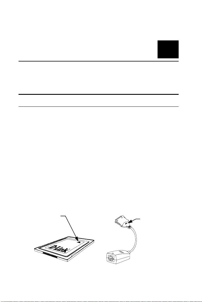
Inside its compact PC-Card package, the D-Link DFE-650 holds an
Ethernet controller, network processing interface, 64 Kb RAM data
buffer, a 68-pin PC Card Standard front-end plug which connects to
the notebook PC, and a 15-pin back-end receptacle for connecting
Page 4

DFE-650 Series Fast Ethernet PC Card User's Guide
the media coupler. The DFE-650 requires no pre-installation setup
simply insert its front end int o t he not e book PC's PC-Card slot.
––
The DFE-650 is supplied with a media coupler which plugs into the
back end (15-pin receptacle) of the DFE-650. The other end of the
media coupler has an RJ-45 receptacle which receives the network
cable. The media coupler features LED indications for linkage and
activity states, and for the speed and duplex settings.
About Fast Ethernet
Fast Ethernet is a network technology specified by IEEE Standard
802.3u. It extends the traditional 10Mbps (10 megabit/sec)
Ethernet technology to achieve 100Mbps (100 megabit/sec)
transmission and reception. Because Fast Ethernet retains the
traditional Ethernet CSMA/CD (Carrier Sense, Multiple Access,
Collision Detect) protocol, it remains wholly compatible with
10Mbps Ethernet while providing a tenfold increase in network
capacity.
The Fast Ethernet standard specifies three subtypes, corresponding
to three media types:
100Base-TX (using two twisted pairs in EIA 568 Category 5
UTP or STP cable)
100Base-T4 (using four twisted pairs in a Category 3,
Category 4, or Category 5 UTP cable)
100Base-FX (using two fiber-optic strands).
D-Link DFE-650 Series Fast Ethernet PC Cards offer half-duplex
100Base-TX operation (in Category 5 twisted-pair cable
environments). These products do not support 100Base-T4 or
100Base-FX operation. To provide for traditional 10Mbps Ethernet
operation in twisted-pair cable environments, the DFE-650 series
2
Introduction
Page 5

DFE-650 Series Fast Ethernet PC Card User's Guide
also offers 10Mbps Ethernet operation, in full-duplex and halfduplex modes. Selection of the best operation mode in any given
installation is automatically governed by autonegotiation.
About Autonegotiation
The basic idea of autonegotiation can be understood by reflecting
for a moment on the familiar process of making a dialup connection
between two modems. You have probably heard some
gravelly−sounding exchanges between your local modem and a
modem at the other end of a telephone line. (These exchanges are
ordinarily played out through a speaker in your local modem). As
irritating as those few seconds of noise may be, they do let you
know that your modem and the remote modem are on the job,
preparing for your intended communication with the remote
computer.
The preparatory work of the two mode ms during those fe w seconds
before you see the “connect” message is to
negotiate
communication scheme which is supported by both modems, and
which is suitable for the quality of the telephone-line connection
between them. The parameters to be settled between the two
modems include best baud rate, compression method, and error
correction method. When the two modems have tested the phoneline quality and have switched to the combination of parameters
which will provide the best data communication, then you are given
the “ connect” message which signals the end of the inter-modem
negotiation and the beginning of your intended communication with
the remote computer.
the best data
Autonegotiation between devices within an Ethernet LAN is similar
in concept, but much briefer. The two devices involved in the
autonegotiation will be your DFE-650 Series PC Card and the hub
or switch through which it is connected into the LAN. (Switches
ordinarily provide autonegotiation functionality; hubs usually do
Introduction
3
Page 6

DFE-650 Series Fast Ethernet PC Card User's Guide
not.) The parameters to be negotiated between the DFE-650 and its
supporting hub or switch include speed (100Mbps = Fast Ethernet,
or 10Mbps = traditional Ethernet) and duplex m ode (half-duplex or
full-duplex).
Startup communication between the two devices occurs when both
devices are operating, the cable connection between them is good,
and the connected notebook PC's network software is loaded. As
soon as those conditions are satisfied, the preparatory process of
autonegotiation between the DFE-650 and its supporting device
begins and proceeds automatically.
If the supporting hub or switch has autonegotiation functionality,
then it and the DFE-650 exchange a series of messages in which
each device signals its capabilities and listens for corresponding
information about the other. The autonegotiation process requires
only a few milliseconds, and the two devices select the best
communication parameters supported by both devices.
If the supporting device does not have autonegotiation
functionality, then its monotone (single capability) message will be
recognized by the DFE-650’s autonegotiation facility, and the DFE650 will simply switch to the one of its own capabilities which
matches that of the supporting device.
Once the autonegotiation is completed, then the line is ready, and it
will provide an optimal data channel between the DFE-650 and the
supporting device. The line will remain ready without further
autonegotiation action until the linkage is broken. Autonegotiation
then reoccurs at any time that the linkage is restored, again making
the line ready for optimal data communications.
4
Introduction
Page 7

DFE-650 Series Fast Ethernet PC Card User's Guide
LED Indicators
The media coupler features three LED indicators:
1. 10/100 Indicator
Steady green indicates Fast Ethernet selected.
Dark indicates 10Mbps Ethernet selected.
2. Half /Full Indicator
Steady green indicates Full-Duplex selected.
Dark indicates Half-Duplex selected.
3. Ln/Act Indicator
Steady green indicates that there is good linkage to the network
("Linkage" state, quiescent).
Flashing green indicates that the DFE-650 is transmitting or
receiving ("Activity" state). In 10Mbps mode, flashing will be
regular and periodic. In 100Mbps mode, flashing may be
irregular, with longer dark periods during heavy traffic activity.
Summary of Features
Features of Model DFE-650TX Fast Ethernet PC Card:
100Mbps and 10Mbps data rates in compliance with IEEE
•
802.3 Ethernet standa rds 100Base-TX and 10Ba se-T
Complies with PCMCIA V2.x, JEIDA V4.x, and 16-Bit PC
•
Card Standards
PC Card Standard 68-pin front-end connector
•
15-pin back-end connector for media coupler
•
Introduction
5
Page 8

DFE-650 Series Fast Ethernet PC Card User's Guide
Built-in 64KB RAM data buffer
•
Full-Duplex capable in 10Mbps mode
•
Autonegotiation per IEEE 802.3u specification
•
No manual setup switches –– fully automatic configuration
•
Low power consumption (2 watts max.)
•
Electronics miniaturization by VLSI and surface-mount
•
fabrication technologies
Laser-welded stainless steel case
•
RJ-45 connector with auto-detection of network speed
•
Software support:
•
Install Program
Diagnostic Program
NDIS 2.0 for Banyan
NDIS 2.0 for IBM Lan Support/Services
NDIS 2.0 for IBM Wrap Server, Lan Server,
and Communication Manager 1.x
NDIS 2.0 for MicroSoft Lan Manager for DOS
NDIS 2.0 for MicroSoft Network Client 3.0
for DOS
NDIS 2.0 for WIN/TCP PathWay Access
SUN PC-NFS V5.0
NetWare Client32 for Windows 95
NetWare Client32 for DOS/Windows 3.1
NetWare Server 3.12
NetWare Server 4.x
6
Introduction
Page 9

DFE-650 Series Fast Ethernet PC Card User's Guide
NetWare DOS ODI
NetWare Lite
Personal NetWare
Windows 95
Windows 95 OSR2
Windows NT 3.51
Windows NT 4.0
Packet Driver for NCSA
Packet Driver for FTP PC/TCP
Packet Driver for IPX
Packet Driver for Winsock
Introduction
7
Page 10
Hardware Installation
g
Unpack and Inspect
2
NOTE:
Open the shipping carton and carefully remove all items. In
addition to this User's Guide, ascertain that you have:
•
•
•
•
Under ordinary circumstances, the DFE-650 Series Fast
Ether net PC Card w ill not be aff ected by static charge as
may be received through your body during handling of the
unit. In special circum-stances where you may carry an
extraordinarily high static charge, it is good practice to
reduce the charge by touching a ground before handling the
DFE-650.
One DFE-650 Series Fast Ethernet PC Card
One plastic storage bag for the PC Card
One media coupler
One D-Link DFE-650 Series Fast Ethernet PC Card Driver
diskette
Yellow arrow
on top side of
PC Card points
to front end plu
DF E -65 0 S eries
Fast Ethernet PC Card
Media Coupler
Triangle
cast into
plastic
marks top
side of plug
Page 11
DFE-650 Series Fast Ethernet PC Card User's Guide
(s)
In the event that any item is missing, or if you find any mismatch or
damage, promptly contact your dealer for correction.
Hardware Installation
Follow these four steps to install the DFE-650 :
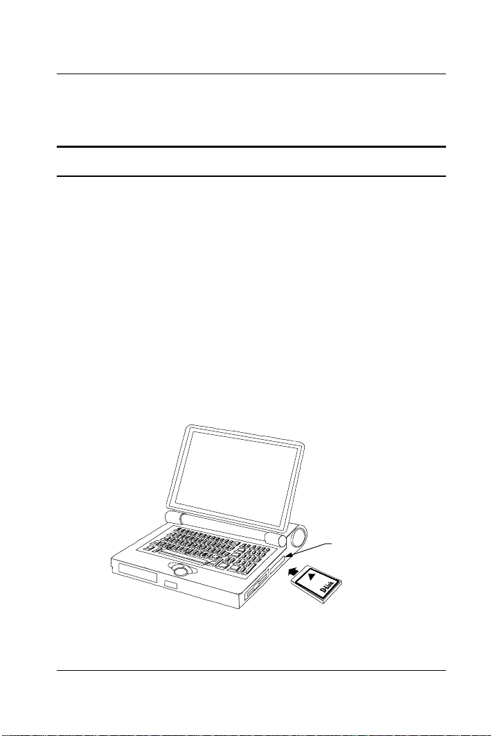
Step 1 Insert the DFE - 650
Under the PCMCIA standard and the corresponding Japanese
JEIDA standard, PC Cards may safely be "hot swapped" –– it is not
necessary to switch the computer's power off before installing or
removing the DFE-650, or any othe r PC Card.
Find/select an open Type II or Type III PC Card slot on your
notebook computer's side or rea r pa nel . Hold the DFE-650 with the
colorful D-Link splash label upward. Notice that the splash label
features a yellow triangle or "arrow," which points to the front end
of the PC Card. Insert the front e nd of the PC Card into the PC
Card slot, and slide the PC Card all the way into the slot until it
reaches a firm stop.
NOTE:
Hardware Installati on
Many notebook PCs feature a stacked pair of PC card slots,
logically (but not physically) designated as Slot 1 and Slot 2.
Type II or Type III
PC Card slot
D-Link color-splash
label facing up
9
Page 12
DFE-650 Series Fast Ethernet PC Card User's Guide
It is most usual for the lower one of the two slots in the
stack to be designated Slot 1, but there are exceptions. In
the subsequent procedure for DFE-650 software
installation, it may be necessary for you to know whether
your DFE-650 is installed in Slot 1 or Slot 2. Under
Windows 95, you can check by opening the Control Panel /
PC Card display. Under DOS it is also possible to make a
software check, but it is more difficult. If you are unable to
determine the DFE-650's slot number in advance, then you
can make a trial-and-error determination later, according to
instructions given in the Software Installation section of this
chapter.
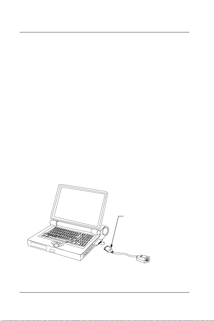
Step 2 Attach the Media Coupler
The back-end receptacle of the DFE-650 remains accessible
(approximately flush with the case of the computer) when the DFE650 is properly seated in its PC Card slot. Taking care to keep the
top side of the media coupler plug up, insert the plug into the DFE650's receptacle until it is firmly seated and latched. (The top side
of the plug is labeled with a triangle molded into the plastic.)
Keep the triang le mark on
top when you plug the media
coupler into the DFE-650
W hen the media coupler plug is firmly seated, it is held in
NOTE:
place by small latching hooks at either side of the plug. To
10
Hardware Installati on
Page 13
DFE-650 Series Fast Ethernet PC Card User's Guide
avoid damage when detaching the plug from the DFE-650, it
is necessary to depress the latch wings of the plug. See
the following section, "Remove Ethernet PC Card."
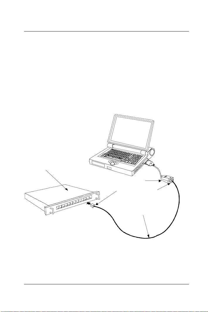
Step 3 Connect to the Network Medium
Make the network connection by running a UTP cable from the
supporting hub to your media coupler. Simply plug one end (RJ-45
connector) of the cable into an available hub port, and plug the
other end (RJ-45 connector) into the RJ-45 socket of the media
coupler.
Ethernet / Fast
Ethernet Hub
Media Coupler
RJ-45 Connectors
UTP Cable
UTP cable connecting media coupler to the supporting hub
Hardware Installati on
11
Page 14

DFE-650 Series Fast Ethernet PC Card User's Guide
Step 4 Confirm Connection (Ln/Act Indicator)
When the notebook computer's power is ON, the DFE-650 is firmly
seated in the slot connector, the media adapter plug is firmly
engaged (and latched) in the back-end receptacle of the DFE-650,
the media adapter has a good cable connection to the supporting
hub, and the supporting hub is power on and functioning properly,
then the media coupler’s Ln/Act LED glows steady green
("linkage" state).
If the Ln/Act LED remains dark without apparent cause, then the
most likely fault is poor engagement of the 68-pin front-end plug.
Review the following section titled "Remove the DFE-650," then
remove the DFE-650 from its slot. Repeat the procedures of the
above Step 1, "Insert the DFE-650," t aking care to ensure that the
DFE-650 is right side up and front-end first, and that it seats firmly
in a suitable PC Card slot of your notebook. Repeat procedures of
Steps 2 and 3 as necessary get the Ln/Act LED confirmation.
NOTE:
You might need to wait a few seconds following notebook
powerup, or following insertion of a PC Card, for the
software processing to be completed. The Ln/Act indicator
will rem ain dark until t he soft wa re processing is completed.
Remove the PC Card
Follow these two steps to remove the DFE-650 it s slot:
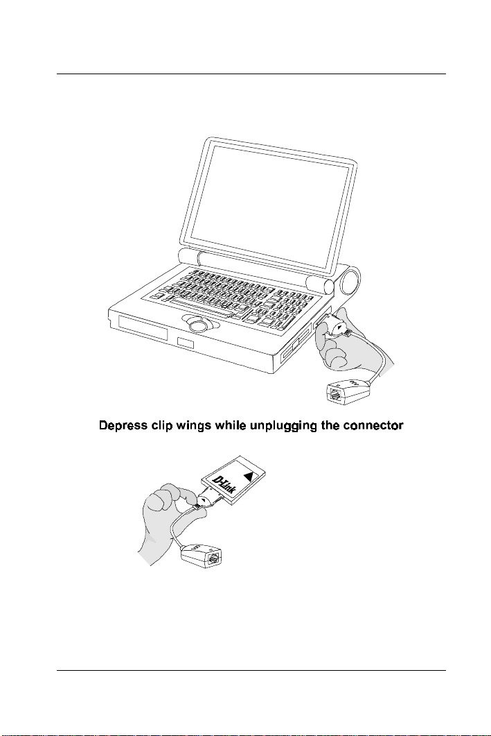
Step 1 Disconnect the Media Coupler Plug from the DFE-650
Unplug the media coupler from the DFE-650 before ejecting the
DFE-650 from the PC Card slot. The me dia couple r plug is held in
place by small latching hooks at either side of the plug. To remove
the media coupler plug from the DFE-650, it is necessary to unlatch
the hooks by depressing the two small latch wings of the plug. Use
12
Hardware Installati on
Page 15
DFE-650 Series Fast Ethernet PC Card User's Guide
thumb and forefinger to squeeze the latch wings into the plug body
and gently pull the plug out of its receptacle.
Don't pull the connector without depressing the clip wings
WARNING:
Pulling the coupler plug out of its receptacle without
depressing the clip wings will cause d amage to t he plug.
Hardware Installati on
13
Page 16

DFE-650 Series Fast Ethernet PC Card User's Guide
Step 2 Eject t he DFE-650 fro m t he Computer
Firmly press the computer's PC Card Eject button to disengage the
DFE-650 from the slot connector. The DFE-650 will then protrude
from the PC Card slot. Grip its protruding end bet ween your fingers
and withdraw it from the PC Card slot.
Connect the Network Cable
Category 5 UTP cable is good enough to qualify under both the
Fast Ethernet cabling rules and the traditional Ethernet cabling
rules. The maximum individual cable run between any station and
its supporting hub or switch is 100m. The maximum individual
cable run joining two hubs is 10m in general, but is 100m when
both hubs qualify as Ethernet Class 2 Repeaters (
Ethernet hubs do qualify). But these cable runs may need to be
shorter than the given individual maximum lengths, because their
lengths are also restricted by the rule that the maximum
cable run between any two stations is 205m.
Connecting for Fast Ethernet
D-Link
all
aggregated
Category 5 UTP cable is required for Fast Ethernet operation. The
maximum cable run between the DFE-650 and the supporting hub
is 300 ft. The cable must be “straight” (not a “ crossover” cable),
with an RJ-45 plug at each end. Make the network connection by
plugging one end of the cable into the RJ-45 receptacle of the
media coupler, and t he othe r e nd int o a port of t he supporting hub.
Connecting for 10Mbps Ethernet
Category 3, Category 4, and Category 5 UTP cable, as well as
EIA/TIA - 568 100-ohm STP cable, all qualify under traditional
Ethernet cabli ng rules. The maximum c able run between the DFE-
14
Hardware Installati on
Page 17

DFE-650 Series Fast Ethernet PC Card User's Guide
650 and the supporting hub is 300 ft. The cable m ust be “ straight”
(not a “ crossover” cable) with RJ-45 plug at each end. Make the
network connection by plugging one end of the cable into the RJ-45
receptacle of the DFE-650, and the other end into a port of the
supporting hub.
Hardware Installati on
15
Page 18

3
Software Installation
Hardware installation as described in Chapter 2 must be completed
before you proceed with software installation.
Instructions for software installation are given as README files on
the D-Link DFE-650 Series Fast Ethernet PC Card Driver diskette.
The diskette also holds the Installation Director program, which
helps you access the installation instructions appropriate to your
station OS and the network environment.
Run Installation Director
For proper function of Installation Director, it is necessary that the
DFE-650 to be plugged into a PC Card slot of the notebook PC.
Ascertain that the DFE-650 is in place, according to Step 1 of
Hardware Installation, Chapter 1, then insert the D-Link DFE-650
Series Fast Ethernet PC Card Driver diskette into the diskette drive
of the notebook PC. Then select that drive as the active drive. In
the Run dialog box, or at the command prompt, type the letter
designator for that drive (here assumed to be A), and complete the
line as follows:
A:\install.exe
Then key
to, and display, the appropriate installation instructions.
Installation Director provides installation instructions for every
combination of plat form OS and network environm ent in which t he
DFE-650 can be used.
<Enter>
to run Installation Director. It will guide you
Page 19

DFE-650 Series Fast Ethernet PC Card User's Guide
During your Installation Director run, if you choose DOS as your
station OS, then in some cases Installation Director will provide
additional services. In such cases, you will be prompted to select a
target directory for storage of software modules that Installation
Director will copy over from the D-Link DFE-650 Series Fast
Ethernet PC Card Driver diskette. The README te xt will provide
full information on the additional services provided..
Installation Director also provides access to the Diagnostic
Program, which may be used to check t he hardware components of
the DFE-650, as well as its proper interoperation with your
network.
For the case that you have a Novell NetWare network environment
and your notebook PC workstation is running MS-DOS (or
equivalent) or Windows 3.1, then Installation Director will lead you
to the appropriate installation README, and you will also find
expanded installation instructions in the following subsections of
this chapter. Refer to whichever instructions you find most
comfortable.
Expanded Installation Instructions:
DOS Platform in NetWare Network
If your notebook PC is running MS-DOS or an equivalent OS, then
you have a choice between two flavors of NetWare client software.
You can choose to install the traditional 16-bit NetWare Client for
DOS, or you can install the 32-bit NetWare Client32 for DOS.
Both types of client software will provide excellent service. It is
not certain whether there is a performance benefit in using the 32bit client software under DOS. But the procedure for i nstallation of
the 32-bit client software is by far more complicated. Thus you
might choose to make an overview comparison of the following
installation instructions for the two kinds of client software before
you decide which to install.
Software Installation
17
Page 20

DFE-650 Series Fast Ethernet PC Card User's Guide
Installing 16-bit NetWare Client for DOS
Installation Director includes a Quick Install option for the DFE650 support software required for interoperation with the 16-bit
NetWare Client for DOS. The scr een text, status line guide text,
and helptext of Installation Director will assist you through the
Quick Install procedure.
Installing NetWare Client32 for DOS
Installation of the 32-bit support software for the DFE-650 can only
be accomplished as part of a new installation, or a re-installation of
the Client32 software on your notebook PC workstation. The
NetWare Client32 software includes a DOS-based installer
program, INSTALL.EXE, which is used for the original
installation, and for any necessary re-installation, of the Client32
software on your station. Thus INSTALL.EXE is also the
installation program for the DFE-650 support software required for
interoperation with NetWare Client32 for DOS.
Before you can proceed with any of the steps which follow, it will
be necessary for you to find a source for the NetWare Client32
software. Depending on decisions which have been made by the
NetWare administrator for your LAN, the Client32 software may be
available from a NetWare server on the LAN or, alternatively, it
may be necessary for you to install from the Client32 CD-ROM or
diskettes. If you are in doubt as to the proper source for the
Client32 software, please consult your NetWare administrator.
Irrespective which form your source takes, you will need to identify
the directory which holds the Client32 for DOS software. If your
source for the Client32 software is the Novell NetWare 4.11 CDROM, then the appropriate directory will be (assuming that the CDROM drive is E:),
E:\PRODUCTS\DOSWIN32\IBM_6
18
Software Installation
Page 21

DFE-650 Series Fast Ethernet PC Card User's Guide
Navigate to the appropriate directory in your Client32 source, so
that it is your active directory, and find INSTALL.EXE in that
directory. The n a t t he DOS prom pt (shown here a s
), type:
>
> INSTALL.EXE
and
<Return>
screen in the INSTALL.EXE run will be the "Select the products"
screen.
. Following the copyright notice screen, the next
"Select the products" Screen
This screen offers simultaneous installation of several network
software packages. NetWare Client 32 for DOS app ears at t he top
of the list. Follow the on-screen instructions, and select the
checkbox at the left of NetWare Client 32 for DOS:
[X] NetWare Client 32 for DOS
For the purpose of basic LAN operations, it is not necessary to
select any of the other products. If you are in doubt whether any of
the other packages offere d by t his scree n should be inc l uded in your
installation, then consult your LAN administrator. After the proper
selections are made (marked with an X), key
<F10>
to continue.
"Select a LAN Driver Type" Screen
In this screen, use the up or down arrow keys to highl ight
32-bit LAN drivers
Then key
<F10>
"32-Bit Netw ork Board Drivers" Screen
to continue.
Use the down arrow key, or the Page Down key to scroll to the
bottom of the long list of driver modules (drivers which are
included with the NetWare software). At the bottom of the list,
Software Installation
19
Page 22

DFE-650 Series Fast Ethernet PC Card User's Guide
following the last of the included drivers, there are some additional
options. Highlight
USER SPECIFIED 32 BIT DRIVER
Then key
<F10>
to continue.
"Insert The Driver Di sk" Dialog Box
Insert the D-Link DFE-650 Series Fast Ethernet PC Card Driver
diskette into a diskette drive of the notebook PC. Type this pathname into the textbox (here assuming the diskette drive to be Drive
A):
A:\NETWARE\32BITLAN\
Then key
DFE-650 driver name appears highlighted in the "32-Bit Network
Board Drivers" screen. Key
<Enter>
"Settings for D-Link DFE-650 Fast Ethernet PC Card
Driver"
This screen provides control of four settings. The
setting is an aggregate setting which includes Line Speed
Type
(10Mbps or 100Mbps) and Duplex (Half Duplex or Full Duplex). It
is recommended that you deselect all line speed and duplex
settings, by celecting “none” as
WARNING:
It is ordinarily best not to change either of the next two settings,
Driver Retries
values. The first of these two parameters affects the errorcorrection processing of defective data packets. The default value
to continue. The dial og box closes, and the
<F10>
to continue.
Connection
Connection Type
Whenever any value is shown for either Line Speed
or Duplex (i.e., the Connection Type setting is
different from “none”), then the entire autonegot iation
function of the DFE-650 will b e disabled (turned off).
or
Frame Type
, from their default
.
20
Software Installation
Page 23

DFE-650 Series Fast Ethernet PC Card User's Guide
is 5, and that is ordinarily a suitable value. The second parameter is
a list of the data frame formats that the DFE-650 and the client
software will be enabled to handle. The default setting enables four
different frame types. That is the maximum range of frame types,
and that is the most appropriate choice in most environments.
The last parameter,
blank, as well. It provides for entry of an alias hardware address,
which is rarely needed.
When your entries are settled, key
Node Address
, should ordinarily be left
<Esc>
to continue.
"Installation Configuration Summary" Screen
This is the last screen before the automatic portion of the
installation. It offers a default target path/directory name, and
allows for your option/permission to automatically alter the
AUTOEXEC. B AT and CONFIG.SYS f iles.
If the offered default path/directory name for the installation is not
acceptable, then key in the path/directory name of your choice. In
all events, make a note of the path/directory name, which will be
needed in the "Edit STARTNET.BAT" section, below.
The permission choice is captioned
Modify AUTOEXEC.BAT and CONFIG.SYS:
If you elect
into your AUTOEXEC.BAT file. In that case, the network
software will automatically be loaded each time you power up the
notebook PC.
If you elect
STARTNET.BAT
time that you want to enable the notebook PC for network
operation. If you want to maximize your notebook PC's resources
which will be available during off-line operations, just choose
, then a STARTNET.BAT command will be added
Yes
, then it will be necessary for you to enter the
No
command manually at the DOS prompt any
No
Software Installation
21
Page 24

DFE-650 Series Fast Ethernet PC Card User's Guide
(key an n, followed by
to enter the
and prepare for network operations.
Key
<F10>
portion of the installation process. (Or key
abort.)
STARTNET.BAT
to approve the installation and initiate the automatic
<Enter>
). And you must then remember
command each time you connect
<Alt + F10>
to
Final Screen of INSTALL.EXE
At completion of the INSTALL.EXE run, there will be an a screen
of advisory information which also instructs you to reboot the
notebook PC. In order to avoid some troublesome diagnostics
which would follow a restart at this time, it is necessary to edit the
file STARTNET.BAT before the restart. Key
INSTALL.EXE.
<ENTER>
to exit
Edit ST ARTNET.BAT
At the DOS prom pt, c hange active directory to the target directory
(named in the Installation Configuration Summary screen). Then
use the DOS Edit utility to edit STARTNET.BAT. For example:
C:\NOVELL\CLIENT32\> EDIT STARTNET.BAT
For each enabled frame type (four types at maximum),
STARTNET.BAT will include a line similar to this shortened
example:
LOAD C:\...\DFE650.LAN FRAME=...
Edit each such statement (there will be a maximum of four) as
follows: just ahead of the FRAME keyword, insert "
separated by at least one space before and after (but if you know
that the DFE-650 is in PC Card Slot No. 2 of the not ebook PC, then
you should insert "
then read,
22
SLOT=2
). The shortened exam ple a bove would
SLOT=1
Software Installation
"
Page 25

DFE-650 Series Fast Ethernet PC Card User's Guide
LOAD C:\...\DFE650.LAN SLOT=1 FRAME=...
When you have completed the edit for each such line in
STARTNET.BAT, then save STARTNET.BAT and e xit from Edit.
If you are uncertain whether the DFE-650 occupies Slot 1 or Slot 2,
and you have entered the wrong slot number, the n when you restart
the notebook PC, there will be a diagnostic which advises that "the
PC Card is not present" and there will be no network connection. If
you do not get a network connection upon your restart, then rework
your editing of STARTNET.BAT, entering the alternate PC Card
Slot Number (substitute SLOT=2 in each place where you have
added SLOT=1).
Restart the notebook PC. Excepting the possibility that the wrong
PC Card Slot Number is indicated in STARTNET.BAT, you should
get a NetWare login upon this restart.
Expanded Installation Instructions:
Windows 3.1 Platform in NetWare Network
If your notebook PC station is running Windows 3.1, then you need
to install Client32 for DOS. (Fundamentally, the DFE-650 support
software modules to be installed are the same under Windows 3.1
and DOS. But the Windows 3.1-based installer program
SETUP.EXE does produce a different result from the installation
made by the DOS-based installer, INSTALL.EXE.)
Installing NetWare Client32 for DOS (under Windows 3.1)
Installation of the support software for the DFE-650 can only be
accomplished as part of a new installation, or a re-installation of the
Client32 software on your notebook PC. The NetWare Client32
software includes a Windows-based installer program, SETUP.EXE
which is used for the original installation, and for any necessary reinstallation, of NetWare Client32 for DOS on your station.. Thus
Software Installation
23
Page 26

DFE-650 Series Fast Ethernet PC Card User's Guide
the NetWare SETUP.EXE program is also the installation program
for the DFE-650 software.
Before you can proceed with any of the steps which follow, it will
be necessary for you to have a source for the NetWare client
software. Depending on decisions which have been made by the
NetWare administrator for your LAN, the NetWare client software
may be available from a NetWare server on the LAN, or it may be
necessary for you to install from the Novell NetWare CD-ROM or
diskettes. If you are in doubt as to the proper source for your
NetWare client software, then please consult your NetWare
administrator.
Irrespective which form your source takes, you will need to identify
the directory which holds the NetWare Client32 for DOS softwar e.
If your source for NetWare Client32 for DOS is the NetWare 4.11
CD-ROM, then the appropriate directory will be (assuming that the
CD-ROM drive is E:),
E:\PRODUCTS\DOSWIN32\IBM_6
In Program Manager, choose RUN under the FILE menu, then, in
the RUN dialog box, choose the
which holds the software source, then navigate to the appropriate
directory. Double-click SETUP.EXE to initiate the installation run.
Browse
button. Select the drive
The initial screen in the SETUP.EXE run is only for the purpose of
selecting the language in which the screen instructions which will
appear during the rest of the SETUP.EXE run. Choose the
button for English, or select another one of the languages offered,
and then choose the
screen then appears.
button. The NetWare Client 32 Welcome
OK
OK
NetWare Clien t 32 Welcome Screen
The Welcome screen provides some orientation information, and
offers you the choice of reading additional technical information in
the README file before going ahead with installation. It might be
24
Software Installation
Page 27

DFE-650 Series Fast Ethernet PC Card User's Guide
your best choice to go ahead with the installation run by choosing
the Continue button. If the installation run is not successful, then
the information given in the README file might be more useful at
this stage in a second attempt.
When you choose the
Agreement screen appears. Accept the provisions of the Software
License Agreement, and continue the installation run, by choosing
the
button. The Directory Locations screen appears.
Yes
Continue
button, the Software License
Directory Lo cat ions Dialog
It is ordinarily suitable to approve the default entries which appear
in this dialog's two text boxes, by simply choosing the
button.
The first textbox provides for selection of a target directory to
receive your computer's copies of the necessary Client 32 files.
The textbox shows a default directory name which is ordinarily a
suitable choice. There is a "browse" button at the right of the
textbox. In all events, it is a good idea to write down the name of
this target directory, because you will need to know the directory
name at a later stage of the installation procedure.
The second textbox in this screen shows the name of the directory
which holds the currently active WIN.COM file. The textbox
provides for entry of a Windows filename different from the
currently active Windows directory. Do not change this textbox
unless you are doing a special procedure involving multiple copies
of the Windows 3.1 system software on your computer.
When you choose
appears.
Next>
, then the ODI Driver Selection screen
Next>
Software Installation
25
Page 28

DFE-650 Series Fast Ethernet PC Card User's Guide
ODI Driver Selection Screen
Disregard the "Board" textbox at the top of this dialog box. In the
"Driver" section below the textbox, select the
button, then choose the
the ODI Driver Path dialog box.
The ODI Driver Path dialog box features a textbox for specification
of the full path filename to the ODI driver (Open Data Interface
driver module) needed for operation of the DFE-650 under DOS or
Windows 3.1 OS. That module is supplied on the D-Link DFE-650
Series Fast Ethernet PC Card Driver diskette.
Insert the D-Link DFE-650 Series Fast Ethernet PC Card Driver
diskette into a diskette drive of your notebook PC (here assumed to
be drive A), and type in the textbox to complete the following
entry:
Other Boards
32 bit
button. This brings up
option
A:\NETWARE\32BITLAN\DFE650.LAN
Then choose the OK button to close the ODI Driver Path dialog
box. In the Select a Board dialog box which then appears, there
will be just one entry:
PC Card Driver
installing the DFE-650, then choose the
Select a Board dialog box.
D-Link
. Click that entry to confirm that you are
DFE-650 Fast Ethernet
button to close the
OK
This returns control to the ODI Driver Selection dialog box. Now
choose the
dialog box appears.
Driver Settings
button. The Driver Settings
Driver Settings Screen
This screen provides control of four settings. The
setting is an aggregate setting which includes Line Speed
Type
(10Mbps or 100Mbps) and Duplex (Half Duplex or Full Duplex). It
is recommended that you deselect all line speed and duplex
settings, by celecting “none” as
26
Connection Type
Connection
.
Software Installation
Page 29

DFE-650 Series Fast Ethernet PC Card User's Guide
WARNING:
It is ordinarily best not to change either of the next two settings,
Driver Retries
values. The first of these two parameters affects the errorcorrection processing of defective data packets. The default value
is 5, and that is ordinarily a suitable value. The second parameter is
a list of the data frame formats that the DFE-650 and the client
software will be enabled to handle. The default setting enables four
different frame types. That is the maximum range of frame types,
and that is the most appropriate choice in most environments.
The last parameter,
blank, as well. It provides for entry of an alias hardware address,
which is rarely needed.
When your entries are choose the OK button to continue. This
returns control once more to the ODI Driver Selection dialog box.
Choose the
dialog box appears.
Whenever any value is shown for either Line Speed
or Duplex (i.e., the Connection Type setting is
different from “none”), then the entire autonegot iation
function of the DFE-650 will b e disabled (turned off).
Next>
or
Frame Type
Node Address
button to continue. The Additional Options
, from their default
, should ordinarily be left
Additional Options Screen
The Additional Options screen is the last preparatory step before
starting the automatic portion of the installation procedure. This
screen features a checkbox for authorizing modification of your
notebook PC's AUTOEXEC.BAT file, and it also offers the option
to simultaneously install several additional network software
packages.
If you select the
NetWare Client 32
command will be added into your
case, the network software will automatically be loaded each time
you power up the notebook PC.
Software Installation
Update AUTOEXEC.BAT to load
checkbox, then a
AUTOEXEC.BAT
STARTNET.BAT
file. In that
27
Page 30

DFE-650 Series Fast Ethernet PC Card User's Guide
If you de-select the checkbox, then it will be necessary for you to
run
STARTNET.BAT
the notebook PC for network operation. If you want to maximize
your notebook PC's resources which will be available during offline operations, then de-select the checkbox (so that it is "blank").
Then remember to run
and prepare for network operations.
For the purpose of basic LAN operations, it is not necessary to
select any of the Additional Software items. If you are in doubt
whether any of the additional software items offered by this screen
should be included in your installation, then consult your LAN
administrator. It might also be useful review the help text which
you can access by choosing the Help button
When you have made your selections in the Additional Options
screen, then choose the
portion of the installation procedure.
When the automatic procedure is completed, SETUP will offer to
restart the computer. In order to avoid some troublesome
diagnostics which would follow a restart at this time, it is necessary
to edit the file STARTNET.BAT before the restart. Exit SETUP.
manually any time that you want to enable
STARTNET.BAT
Next>
button to initiate the automatic
each time you connect
Edit ST ARTNET.BAT
In Program Manager, open a DOS window. At the DOS prompt ,
change active directory to the target directory (named in the
Installation Configuration Summary screen). Then use the DOS
Edit utility to edit STARTNET.BAT. For example:
C:\NOVELL\CLIENT32\> EDIT STARTNET.BAT
For each enabled frame type (four types at maximum),
STARTNET.BAT will include a line similar to this shortened
example:
LOAD C:\...\DFE650.LAN FRAME=...
28
Software Installation
Page 31

DFE-650 Series Fast Ethernet PC Card User's Guide
Edit every such statement (there will be a maximum of four such
statements), as follows: just ahead of the FRAME keyword, insert
"
SLOT=1
" separated by at least one space before and after(but if
you know that the DFE-650 is in PC Card Slot No. 2 of the
notebook PC, then you should insert "
SLOT=2
). The shortened
example above would the n re ad,
LOAD C:\...\DFE650.LAN SLOT=1 FRAME=...
When you have completed the edit for each such line in
STARTNET.BAT, then save STARTNET.BAT and e xit from Edit.
If you are uncertain whether the DFE-650 occupies Slot 1 or Slot 2,
and you have entered the wrong slot number, the n when you restart
the notebook PC, there will be a diagnostic which advises that "the
PC Card is not present" and there will be no network connection. If
you do not get a network connection upon your restart, then rework
your editing of STARTNET.BAT, entering the alternate PC Card
Slot Number (substitute SLOT=2 in each place where you have
added SLOT=1).
Restart the notebook PC. Excepting the possibility that the wrong
PC Card Sl ot Number is indicated in STARTNET.BAT, you should
get a NetWare login upon this restart.
Software Installation
29
Page 32

A
Troubleshooting
Troubleshooting the
If you experience any problems with the hardware installation, first
ascertain that all network cable connections are firm, that the
proper grade of cable is used for the network connection, and that
the cable makeup is correct (straight –– without un-needed
crossovers in the connector wiring). Check that the supporting hub
is power-on and operating normally, and that the hub is properly
qualified (under 10Base-T and/or 100Base-TX standards).
Hardware
Installation
Troubleshooting the Software Installation
You Get the
You are running Installation Director, and in the Main Menu you
have selected
Quick Install 16-bit Driver for Dos Netware Client
The Quick Install run is then interrupted by an error message which
says that the DFE-650 PC Card is not detected by the system.
You have followed the instruction given by the error message, to
repeat Step 1 of the Hardware Installation procedure given at the
beginning of Chapter 2 of the User's Guide. And you have then rerun Installation Director. And the same error message has come up.
%')(0983 3& &DUG 1RW 'HWHFWHG%
Error
Page 33

DFE-650 Series Fast Ethernet PC Card User's Guide
Proceed as follows:
1. Exit Installation Director. Examine the CONFIG.SYS file in
the root directory of your notebook PC's startup drive (hard
drive). Ascertain that CONFIG.SYS contains a DEVICE
statement for Extended Memory Manager (EMM). Such a
statement should resemble the following example,
DEVICE = C:\DOS\EMM386.EXE X=D000-D7FF
2. If there is no similar DEVICE statement in your notebook
PC's CONFIG.SYS file, then edit the CONFIG.SYS file,
adding a statement copied exactly from the above example.
3. If there such a statement in CONFIG.SYS but the "DFE-650
PC Card not detected" error appears on each attempted Quick
Install run anyway, then edit that statement to read exactly the
same as the above example.
4. If, after you have completed the above instructions, the "DFE650 PC Card not detected" error still appears on each
subsequent restart of the notebook PC, then please contact
your dealer or your nearest D-Link office, as listed at the end
of this User's Guide.
You need to "unloa d the conflicting network driver"
You are running Installation Director, and in the Main Menu you
have selected
Quick Install 16-bit Driver for Dos Netware
Client.
Then you have seen the warning message which advises that the
presence in memory of anot her network card driver could cause a
system halt. (That warning messages appears in every Quick Install
run –– it does not indicate that there is another network card driver
already loaded into memory.) Then you have elected to continue
Troubleshooting
31
Page 34

DFE-650 Series Fast Ethernet PC Card User's Guide
the Quick Install run. And the Quick Install run has indeed
produced a halt (system hangup).
If you have not been through all of those steps, then you should not
be reading this. You should be in the Software Installation section
of Chapter 2. And you should be staying on track with your Quick
Install run. Continue reading here
your Quick Install run is
only if
actually obstructed by a system halt (so that you can only restore
your control of the notebook PC by a restart). And
only if
after
your restart (which provides assurance of a "clean" DOS
environment) you have tried Quick Install once more (and
experienced the system halt once more). Only then should you
conclude that you must "unload the conflicting network driver."
Stay Cool
The first thing you need to know is that "unload the conflicting
network driver" is easier said than done. . . . This Troubleshooting
section will provide some guidance, and if you don't have a great
deal of experience in such matters, this guidance will be helpful.
But if you have easy access to a network administrator (or other
resident expert), now might be a good time to go for help. If it is
your choice to have a go at it alone, then don't be hurried or
worried. Just pour yourself a cup of coffee, relax, and read on. If
this Troubleshooting section is not sufficient guidance, and you do
not have ready access to an expert, then help may be available from
the dealer who has supplied your DFE-650, and you can also get
help by calling D-Link Technical Support at the D-Link office
nearest to you (see the list of office locations at the end of this
User's Guid e ) .
"Unload" Really Means "Avoid Loading at Startup"
It is true that driver programs and related software modules, such as
those supplied on your D-Link DFE-650 Series Fast Ethernet PC
Card Driver diskette, are often written so that the addition of a "/u"
switch or "-u" option to the command line for loading the driver
32
Troubleshooting
Page 35

DFE-650 Series Fast Ethernet PC Card User's Guide
will cause unloading of the same driver (if it is in fact already
loaded). But such unloading is only possible under special
circumstances. So, as a practical matter, what we really must do is
avoid loading of the conflicting driver
upon startup of the notebook
PC.
A software installation procedure (such as "Quick Install 16-bit
Driver for DOS NetWare Client") copies the necessary drivers and
related modules from the supplied DFE-650 Series Fast Ethernet
PC Card Driver diskette, into the target directory of the notebook
PC's hard drive or other storage. The installation program also adds
commands to the computer's AUTOEXEC.BAT file, so that each
time the computer is subsequently booted up (and you then make
certain choices in the startup menus, if any), the drivers and related
modules are automatically loaded into memory.
The "conflicting driver" problem now at hand arises because certain
commands already present in your notebook PC's
AUTOEXEC.BAT file are being executed during bootup, and are
causing some kind of previously installed network driver module to
be loaded into memory. The presence of that network driver in
memory is now making it im possible to load the DFE-650 network
driver software (16-bit dri ver for DOS N etWare client).
So the fix is to delete from AUTOEXEC.BAT the line which is
causing the conflicting driver to be loaded. Thus we will
loading of the conflicting driver
when we next restart the notebook
avoid
PC. And the trick is to delete that line from AUTOEXEC.BAT
without deleting or changing anything which needs to remain
unchanged in AUTOEXEC.BAT (so that your notebook PC will
behave as you expect it to after each startup).
So which line of AUTOEXEC.BAT do we need to delete?
Now there is a really good question! It gets right to the heart of the
problem. If you are savvy enough about such matters, then you
may be able to go directly into DOS Edit,
Troubleshooting
33
Page 36

DFE-650 Series Fast Ethernet PC Card User's Guide
C:\> edit autoexec.bat
and find the troublesome line by inspection, and simply delete it.
But if you are that clever, then it is very unlikely that you will be
reading this. So here is a procedure which will help you to identify
the troublesome line of AUTOEXEC.BAT.
Use the
MEM
Command to Help Identify the Conflicting
Network Driver
At the DOS prompt (here re pre sent e d by C: \>), type
C:\> mem /d | find "Program"
exactly as shown here, including the vertical bar (DOS "pipe"
symbol, |), then
<Enter>
. The resulting display of memory
allocation information will be a few rows of tabular data. Here is
an example:
0122E 80 (0K) MSDOS System
Program
01236 2,656 (3K) COMMAND Program
012F8 5,376 (5K) LSL Program
0144F 32,994 (32K) DFE650 Program
01718 16,640 (16K) IPXODI Program
01B28 48,688 (48K) NETX Program
0270B 29,024 (28K) SMARTDRV Program
02E2D 27,952 (27K) MSCDEX Program
03500 4,144 (4K) DOSKEY Program
03610 88,992 (87K) MEM Program
The next-last column lists the names of certain program modules
present in memory. We will disregard all the other columns.
34
Troubleshooting
Page 37

DFE-650 Series Fast Ethernet PC Card User's Guide
Now we can cull that list of program names, by disregarding any
item which is obviously not the name of a network driver. You
might notice that some of the items (as in the example above) are
names of DOS commands. (A convenient way to determine
whether any item is the name of a DOS command is to search for
that name in the alphabetical index of DOS commands which
appears when you type "
help"
at the DOS prompt .) T hus, in our
example, we have a list of ten names, and we can
disrega rd MSDOS, because it is the "System Program," and
thus is not a network driver
disregard COMMAND, because it appears in the
alphabetical list of DOS commands
disregard SMARTDRV, because it appears in the
alphabetical list of DOS commands
disregard MSCDEX, because it appears in the alphabetical
list of DOS commands
disregard DOSKEY, because it appears in the alphabetical
list of DOS commands
disregard MEM, because it appears in the alphabetical list of
DOS commands
This leaves us to deal with just four possibilities as to the name of
the network driver which is conflicting with our Quick Install:
LSL, DFE650, IPXODI, and NETX
Let's call this list the "short list." One of the items in the short list
is certain to be the conflicting driver.
Now It's Trial-and-Error Time
It is good news that the short list is short. The bad news is that
there is only one method guaranteed to determine which of the
Troubleshooting
35
Page 38

DFE-650 Series Fast Ethernet PC Card User's Guide
items on the short list is the culprit (conflicting driver). And that
method is trial and error. So we begin testing each of the items on
the short list in turn. We take the items in the same order as they
appear in the short list (because taking them in that order will
ordinarily lead us to the earliest success). LSL is the first item on
our example short list, so we begin our trial-and-error round by
starting with LSL and following t hi s procedure :
1. Find the AUTOEXEC.BAT line which invokes the first item
in your short list (LSL in our exampl e ):
At the DOS prompt (here re pre sent e d by
C:\>
), type
C:\> find /n/i "LSL" autoexec.bat
then
<RETURN>. T
his will display the line from
AUTOEXEC.BAT which causes the LSL program to be
loaded.
---------- AUTOEXEC.BAT
[2]C:\ODI.DOS\LSL.COM
Ignore the header line of the displa y, which only ident ifies the
subject file. To help locate the LSL line of the
AUTOEXEC.BAT file, the line's line number in
AUTOEXEC.BAT is shown in brackets to the left of the
actual text of the line. If LSL appears in more than one line of
AUTOEXEC.BAT, then you will need to decide which of the
several lines is the one that causes loading –– but it is most
likely that any additional lines will simply be remark lines,
which you can ignore.
Note that in this step, you must name the first item of
short list, rather than LSL, which is used here only for
purposes of example.
2. Edit AUTOEXEC.BAT to cancel out that line.
At the DOS prompt (here re pre sent e d by
C:\>
), type
your
36
Troubleshooting
Page 39

DFE-650 Series Fast Ethernet PC Card User's Guide
C:\> edit autoexec.bat
then
<RETURN>.
The content of AUTOEXEC.BAT is
shown in the Edit window. Notice that the line number of the
cursor position is shown at the right end of the status bar (at
the foot of the Edit window; the line position of the cursor is
shown ahead of a colon, and the column position of the cursor
within the line is shown after the colon).
Take care
not to
introduce any inadvertent changes while you have
AUTOEXEC.BAT in the Edit window. Use the down arrow
key to move the cursor down until you reach the line number
as found in Step 1. Check that the l ine m arke d by t he c ursor is
the same as that displayed in Step 1. Then type in the word
REMARK at the beginning of the line. Immediately save,
then exit from Edit .
3. Remove the D-Link DFE-650 Series Fast Ethernet PC Card
Driver diskette from its drive, and key
DELETE>
to restart the notebook PC.
<CTRL + ALT +
4. At the DOS prompt, insert the D-Link DFE-650 Series Fast
Ethernet PC Card Driver diskette and run Installation Director,
again choosing
Quick Install 16-bit Driver for
DOS NetWare Client
and proceed with the installation run. If the installation run
completes normally, then you are all through with the
problem!
Give yourself a big pat on the back
, and return
"Installing 16-bit NetWare Client for DOS" in Chapter 3 .
5. If the installation run again ends with a crash (halt), then the
short list item we have just tested (LSL in our example case)
is
the culprit. Repeat Step 1 above, but substitute the next
not
program named in your short list (in our example we
substitute DFE650 in place of LSL):
C:\> find /n/i "DFE650" autoexec.bat
Troubleshooting
37
Page 40

DFE-650 Series Fast Ethernet PC Card User's Guide
Note that in this step, you must name the next item of
your
short list, rather than DFE650, which is used here only for
purposes of example.
6. Repeat Step 2 above, but before you REMARK the line which
invokes DFE650 (in the example case) you must
editing previously done in Step 2
. That is (in our example
undo the
case), delete the six letters REMARK from the beginning of
the line which invokes LSL (first item in
short list).
your
Then go ahead and REMARK the line which invokes the next
program named in your short list (DFE650 in our example
case). Immediately save, then exit from Edit.
7. Repeat Step 3
8. Repeat Step 4
9. If necessary, repeat Step 5.
10. Repeat Step 6
If You're Still Reading . . .
It's hard to guess why you might still be reading this
Troubleshooting section, but maybe it's because you are still having
trouble. So here is a little bit of clarification to the above procedure
description. The example references (to LSL and DFE650) will
only be useful in getting started on the cyclic pattern of the above
instructions. After you are well into the rhythm of it, the example
references are best ignored because they are specifically
appropriate to the initial passes. By the time you get to testing the
third item in your short list, the example references in the above
description will be excess baggage –– refer only to
your
short list.
You Are Now an Uncertified Expert!
If you are not still having trouble, but you are still reading, then
maybe it is because you are simply excited about your success in
38
Troubleshooting
Page 41

DFE-650 Series Fast Ethernet PC Card User's Guide
the above "trial by fire." You are excited about being an
Uncertified Expert. Congratulations! But, you ask: How is a
Certified Expert a ny di ffere nt ?
The difference is only this: certain items in your short list would be
old friends to the Certified Expert. He or she would have
recognized them by name just as surely as you know your friend's
face when you meet in a crowd. In the example case, the short list
included four items,
LSL, DFE650, IPXODI, and NETX.
The Certified Expert would have recognized NETX as a NetWare
shell module, therefore not the culprit conflicting network driver.
And the Certified Expert would have recognized LSL as most likely
being a link support layer module, which functions in a higher layer
of the communications system, while a hardware-specific network
adapter driver functions in a lower (physical) layer. And the
Certified Expert would have recognized or guessed that the
IPXODI module is a protocol-layer element concerned with the
transmission/reception of NetWare IPX packets by an ODI (Open
Data Interface) network adapter. Thus the Certified Expert would
have known, by a simple process of elimination, that the DFE650
element is the conflicting driver. So the Certified Expert would
have been able to skip the trial and error process, which we needed
to grunt through, in order to know which line of AUTOEXEC.BAT
to cancel.
And here is one more bit of insight. Since the conflicting driver
must be a hardware-specific driver, then it is likely to bear a name
which suggests the model name of the PC Card it serves. The
Certified Expert will be acquainted with a large range of PC Card
products. So he or she will be able to know which element in the
short list has a name which suggests a PC Card model name. Now
you know what lies between you and being a Certified Expert.
Troubleshooting
39
Page 42

DFE-650TX
Specifications
Network Type:
Ethernet 100Base-TX
•
Ethernet IEEE 802.3u standard for 100Mbps baseband
CSMA/CD local area network
Ethernet 10BASE-T
•
Ethernet IEEE 802.3 standard for 10Mbps baseband CSMA/CD
local area network
Jumperless Hardware
Autonegotiation functionality
Media interface: RJ-45
LAN Chip Set:
Interface controller, DLI-0019C
•
Transceiver interface, LTX970QC
•
EMI Certifications:
FCC Class B
VCCI Class 2
CISPR B
Canada ICES-003, Class B
CE Certification
Host interface: PCI Bus (Bus Master)
I/O base address assigned by Plug and Play system
Interrupt Number Assigne d by Pl ug a nd Pl ay syste m
B
Page 43

DFE-650TX Fast Ethernet PC Card User's Guide
Physical Dimensions: 85.6 × 54.0 × 5.0 mm
Environment:
Storage:
Operating: 0° to 55° C, (32° to 131° F)
Humidity: 10% t o 90% non-conde nsing
to 80°C, (4° to 176° F)
−20°
Power Consumption: 2.0W
PCB Construction: 2 layers
Device Drivers*
NDIS 2.0 for Banyan
•
NDIS 2.0 for IBM Wrap
•
Server, Lan Server,
and Communication
Manager 1.x
NDIS 2.0 for MicroSoft
•
Network Client 3.0 for
DOS
SUN PC-NFS V5.0
•
NetWare Client32 for
•
DOS/Windows 3.1
NetWare Server 4.x
•
NetWare Lite
•
Windows 95
•
Windows NT 3.51
•
Packet Driver for NCSA
•
Packet Driver for IPX
•
*Check
http://www.dlink.com
NDIS 2.0 for IBM Lan
•
Support/Services
NDIS 2.0 for
•
MicroSoft Lan Manager
for DOS
NDIS 2.0 for WIN/TCP
•
PathWay Access
NetWare Client32 for
•
Windows 95
NetWare Server 3.12
•
NetWare DOS ODI
•
Personal NetWare
•
Windows 95 OSR2
•
Windows NT 4.0
•
Packet Driver for FTP
•
PC/TCP
Packet Driver for
•
Winsock
for newest
DFE-650TX Specifications
41
Page 44

DFE-650 Series Fast Ethernet PC Card User's Guide
releases of drivers.
42
DFE-650TX Specifications
Page 45

[this page is a placeholder only -- l/c standard]
Index
100Mbps/10Mbps LED, 6; 18
10Mbps Ethernet, 1; 2; 5; 10
Active LED, 6; 18
autonegotiation, 2 - 4; 5; 19
BIOS Program, 8; 17
Boot ROM, 7; 8
cabling, 2; 3; 5; 9; 10; 12; 15;
17; 18
CMOS Setup, 9; 1 7
Collision LED, 6; 18
communication parameters, 4
D-Link DFE-650 Ser i es Fas t
Ethernet PC Card Driver
, 7; 15
diskette
D-Link WWW Ser ver, 20
Driver progr ams, 20
Ethernet standards, 5; 19
expansion slot, 8
Fast Ethern et, 1 - 3; 5; 9
Full/Half Duplex LED, 6; 18
hub, autonegotiation function, 3
- 4
latency, 5
LED indicators, 6; 18
Link LED 6; 18
Loopbac k tes ts, 12; 15
networ k operating system, 11;
20
PCI Bus, 4; 5; 8; 19
README files, 11
second station, 12; 15; 16
Softwa re upgrades, 20
static charge, 7
Page 46

Contacting Technical Support
You can find software updates and user documentation on the D-Link website.
D-Link provides free technical support for customers within the United States and within
Canada for the duration of the warranty period on this product.
U.S. and Canadian customers can contact D-Link technical support through our web
site, or by phone.
Tech Support for customers within the United States:
D-Link Technical Support over the Telephone:
(877) 453-5465
24 hours/ 7 days a week
D-Link Technical Support over the Internet:
http://support.dlink.com
email:support@dlink.com
Tech Support for customers within Canada:
D-Link Technical Support over the Telephone:
(800) 361-5265
Monday to Friday 7:30am to 12:00am EST
D-Link Technical Support over the Internet:
http://support.dlink.ca
email:support@dlink.ca
When contacting technical support, please provide the following information:
·
·
·
Serial number of the unit
Model number or product name
Software type and version number
Page 47

Subject to the terms and conditions set forth herein, D-Link Systems, Inc. (“D-Link”)
provides this Limited Warranty:
• Only to the person or entity that originally purchased the product from D-Link or its
authorized reseller or distributor, and
• Onl y for products purchased and delivered within the fifty states of the United States,
the District of Columbia, U.S. Possessions or Protectorates, U.S. Military
Installations, or addresses with an APO or FPO.
Limited Warranty: D-Link warrants that the hardware portion of the D-Link product
described below (“Hardware”) will be free from material defects in workmanship and
materials under normal use from the date of original retail purchase of the product, for the
period set forth below (“Warranty Period”), except as otherwise stated herein.
• Hardware (excluding power supplies and fans): One (1) year
• Power supplies and fans: One (1) year
• Spare parts and spare kits: Ninety (90) days
The customer's sole and exclusive remedy and the entire liability of D-Link and its
suppliers under this Limited Warranty will be, at D-Link’s option, to repair or replace the
defective Hardware during the Warranty Period at no charge to the original owner or to
refund the actual purchase price paid. Any repair or replacement will be rendered by DLink at an Authorized D-Link Service Office. The replacement hardware need not be new
or have an identical make, model or part. D-Link may, at its option, replace the defective
Hardware or any part thereof with any reconditioned product that D-Link reasonably
determines is substantially equivalent (or superior) in all material respects to the defective
Hardware. Repaired or replacement hardware will be warranted for the remainder of the
original Warranty Period or ninety (90) days, whichever is longer, and is subject to the
same limitations and exclusions. If a material defect is incapable of correction, or if D-Link
determines that it is not practical to repair or replace the defective Hardware, the actual
price paid by the original purchaser for the defective Hardware will be refunded by D-Link
upon return to D-Link of the defective Hardware. All Hardware or part thereof that is
replaced by D-Link, or for which the purchase price is refunded, shall become the property
of D-Link upon replacement or refund.
Limited Software Warranty: D-Link warrants that the software portion of the product
(“Software”) will substantially conform to D-Link’s then current functional specifications for
the Software, as set forth in the applicable documentation, from the date of original retail
purchase of the Software for a period of ninety (90) days (“Software War ranty Period”),
provided that the Software is properly installed on approved hardware and operated as
contemplated in its documentation. D-Link further warrants that, during the Software
Warranty Period, the magnetic media on which D-Link delivers the Software will be free of
physical defects. The customer's sole and exclusive remedy and the entire liability of DLink and its suppliers under this Limited Warranty will be, at D-Link’s option, to replace the
non-conforming Software (or defective media) with software that substantially conforms to
D-Link’s functional specifications for the Software or to refund the portion of the actual
purchase price paid that is attributable to the Software. Except as otherwise agreed by D-
Page 48

Link in writing, the replacement Software is provided only to the original licensee, and is
subject to the terms and conditions of the license granted by D-Link for the Software.
Replacement Software will be warranted for the remainder of the original Warranty Period
and is subject to the same limitations and exclusions. If a material non-conformance is
incapable of correction, or if D-Link determines in its sole discretion that it is not practical
to replace the non-conforming Software, the price paid by the original licensee for the
non-conforming Software will be refunded by D-Link; provided that the non-conforming
Software (and all copies thereof) is first returned to D-Link. The license granted
respecting any Software for which a refund is given automatically terminates.
Non-Applicability of Warranty: The Limited Warranty provided hereunder for Hardware
and Software portions of D-Link's products will not be applied to and does not cover any
refurbished product and any product purchased through the inventory clearance or
liquidation sale or other sales in which D-Link, the sellers, or the liquidators expressly
disclaim their warranty obligation pertaining to the product and in that case, the product is
being sold "As-Is" without any warranty whatsoever including, without limitation, the
Limited Warranty as described herein, notwithstanding anything stated herein to the
contrary.
Submitting A Claim: The customer shall return the product to the original purchase point
based on its return policy. In case the return policy period has expired and the product is
within warranty, the customer shall submit a claim to D-Link as outlined below:
• The customer m ust submit with the product as part of the claim a written description
of the Hardware defect or Software nonconformance in sufficient detail to allow DLink to confirm the same, along with proof of purchase of the product (such as a copy
of the dated purchase invoice for the product) if the product is not registered.
• The customer must obtain a Case ID Number from D-Link Technical Support at 1-
877-453-5465, who will attempt to assist the customer in resolving any suspected
defects with the product. If the product is considered defective, the customer must
obtain a Return Material Authorization (“RMA”) number by completing the RMA form
and entering the assigned Case ID Number at https://rma.dlink.com/
• After an RMA number is issued, the defective product must be packaged securely in
the original or other suitable shipping package to ensure that it will not be damaged
in transit, and the RMA number must be prominently marked on the outside of the
package. Do not include any manuals or accessories in the shipping package. DLink will only replace the defective portion of the product and will not ship back any
accessories.
• The customer is responsible for all in-bound shipping charges to D-Link. No Cash on
Delivery (“COD”) is allowed. Products sent COD will either be rejected by D-Link or
become the property of D-Link. Products shall be fully insured by the customer and
shipped to D-Link Systems, Inc., 17595 Mt. Herrmann, Fountain Valley, CA
92708. D-Link will not be held responsible for any packages that are lost in transit to
D-Link. The repaired or replaced packages will be shipped to the customer via UPS
Ground or any common carrier selected by D-Link. Return shipping charges shall be
prepaid by D-Link if you use an address in the United States, otherwise we will ship
the product to you freight collect. Expedited shipping is available upon request and
provided shipping charges are prepaid by the customer.
D-Link may reject or return any product that is not packaged and shipped in strict
compliance with the foregoing requirements, or for which an RMA number is not visible
from the outside of the package. The product owner agrees to pay D-Link’s reasonable
handling and return shipping charges for any product that is not packaged and shipped in
accordance with the foregoing requirements, or that is determined by D-Link not to be
defective or non-conforming.
What Is Not Covered: The Limited Warranty provided herein by D-Link does not cover:
Products that, in D-Link’s judgment, have been subjected to abuse, accident, alteration,
modification, tampering, negligence, misuse, faulty installation, lack of reasonable care,
.
Page 49

repair or service in any way that is not contemplated in the documentation for the product,
or if the model or serial number has been altered, tampered with, defaced or removed;
Initial installation, installation and removal of the product for repair, and shipping costs;
Operational adjustments covered in the operating manual for the product, and normal
maintenance; Damage that occurs in shipment, due to act of God, failures due to power
surge, and cosmetic damage; Any hardware, software, firmware or other products or
services provided by anyone other than D-Link; and Products that have been purchased
from inventory clearance or liquidation sales or other sales in which D-Link, the sellers, or
the liquidators expressly disclaim their warranty obligation pertaining to the product.
While necessary maintenance or repairs on your Product can be performed by any
company, we recommend that you use only an Authorized D-Link Service Office.
Improper or incorrectly performed maintenance or repair voids this Limited Warranty.
Disclaimer of Other Warranties: EXCEPT FOR THE LIMITED WARRANTY SPECIFIED
HEREIN, THE PRODUCT IS PROVIDED “AS-IS” WITHOUT ANY WARRANTY OF ANY
KIND WHATSOEVER INCLUDING, WITHOUT LIMITATION, ANY WARRANTY OF
MERCHANTABILITY, FITNESS FOR A PARTICULAR PURPOSE AND NONINFRINGEMENT. IF ANY IMPLIED WARRANTY CANNOT BE DISCLAIMED IN ANY
TERRITORY WHERE A PRODUCT IS SOLD, THE DURATION OF SUCH IMPLIED
WARRANTY SHALL BE LIMITED TO THE DURATION OF THE APPLICABLE
WARRANTY PERIOD SET FORTH ABOVE. EXCEPT AS EXPRESSLY COVERED
UNDER THE LIMITED WARRANTY PROVIDED HEREIN, THE ENTIRE RISK AS TO
THE QUALITY, SELECTION AND PERFORMANCE OF THE PRODUCT IS WITH THE
PURCHASER OF THE PRODUCT.
Limitation of Liability: TO THE MAXIMUM EXTENT PERMITTED BY LAW, D-LINK IS
NOT LIABLE UNDER ANY CONTRACT, NEGLIGENCE, STRICT LIABILITY OR OTHER
LEGAL OR EQUITABLE THEORY FOR ANY LOSS OF USE OF THE PRODUCT,
INCONVENIENCE OR DAMAGES OF ANY CHARACTER, WHETHER DIRECT,
SPECIAL, INCIDENTAL OR CONSEQUENTIAL (INCLUDING, BUT NOT LIMITED TO,
DAMAGES FOR LOSS OF GOODWILL, LOSS OF REVENUE OR PROFIT, WORK
STOPPAGE, COMPUTER FAILURE OR MALFUNCTION, FAILURE OF OTHER
EQUIPMENT OR COMPUTER PROGRAMS TO WHICH D-LINK’S PRODUCT IS
CONNECTED WITH, LOSS OF INFORMATION OR DATA CONTAINED IN, STORED
ON, OR INTEGRATED WITH ANY PRODUCT RETURNED TO D-LINK FOR
WARRANTY SERVICE) RESULTING FROM THE USE OF THE PRODUCT, RELATING
TO WARRANTY SERVICE, OR ARISING OUT OF ANY BREACH OF THIS LIMITED
WARRANTY, EVEN IF D-LINK HAS BEEN ADVISED OF THE POSSIBILITY OF SUCH
DAMAGES. THE SOLE REMEDY FOR A BREACH OF THE FOREGOING LIMITED
WARRANTY IS REPAIR, REPLACEMENT OR REFUND OF THE DEFECTIVE OR NONCONFORMING PRODUCT. THE MAXIMUM LIABILITY OF D-LINK UNDER THIS
WARRANTY IS LIMITED TO THE PURCHASE PRICE OF THE PRODUCT COVERED
BY THE WARRANTY. THE FOREGOING EXPRESS WRITTEN WARRANTIES AND
REMEDIES ARE EXCLUSIVE AND ARE IN LIEU OF ANY OTHER WARRANTIES OR
REMEDIES, EXPRESS, IMPLIED OR STATUTORY.
Governing Law: This Limited Warranty shall be governed by the laws of the State of
California. Some states do not allow exclusion or limitation of incidental or consequential
damages, or limitations on how long an implied warranty lasts, so the foregoing limitations
and exclusions may not apply. This Limited Warranty provides specific legal rights and
you may also have other rights which vary from state to state.
Trademarks: D-Link is a registered trademark of D-Link Systems, Inc. Other trademarks
or registered trademarks are the property of their respective owners.
Copyright Statement: No part of this publication or documentation accompanying this
product may be reproduced in any form or by any means or used to make any derivative
such as translation, transformation, or adaptation without permission from D-Link
Corporation/D-Link Systems, Inc., as stipulated by the United States Copyright Act of
1976 and any amendments thereto. Contents are subject to change without prior notice.
Copyright 2005 by D-Link Corporation/D-Link Systems, Inc. All rights reserved.
Page 50

CE Mark Warning: This is a Class B product. In a domestic environment, this product
may cause radio interference, in which case the user may be required to take adequate
measures.
FCC Statement: This equipment has been tested and found to comply with the limits for
a Class B digital device, pursuant to part 15 of the FCC Rules. These limits are designed
to provide reasonable protection against harmful interference in a residential installation.
This equipment generates, uses, and can radiate radio frequency energy and, if not
installed and used in accordance with the instructions, may cause harmful interference to
radio communication. However, there is no guarantee that interference will not occur in a
particular installation. If this equipment does cause harmful interference to radio or
television reception, which can be determined by turning the equipment off and on, the
user is encouraged to try to correct the interference by one or more of the following
measures:
• Reorient or relocate the receiving antenna.
• Increase the separation between the equipment and receiver.
• Connect the equipment into an outlet on a circuit different from that to which the
receiver is connected.
• Consult the dealer or an experienced radio/TV technician for help.
For detailed warranty information applicable to products purchased outside
the United States, please contact the corresponding local D-Link office.
Page 51

Registration
Product registration is entirely voluntary and failure to complete or
return this form will not diminish your warranty rights.
 Loading...