


Getting Started Guide
Erste Schritte
Guide de démarrage
Guida introduttiva
Guía de introducción
Краткое руководство пользователя
快速安裝指南
Guia inicial
Petunjuk Pemasangan
本製品のご利用にあたって

About This Guide
Rack Installation
This guide gives step-by-step instructions for setting up
all D-Link Web Smart switches. Please note that the
model you have purchased may appear slightly different
from those shown in the illustrations.
For more detailed information about your switch, its
components, making network connections, and technical
specifications, please refer to the User’s Guide included
with your switch.
Step 1 – Unpacking
Open the shipping carton and carefully unpack its
contents. Please consult the packing list located in the
User Guide to make sure all items are present and
undamaged. If any item is missing or damaged, please
contact your local D-Link reseller for replacement.
- One D-Link Web Smart Switch
- Rack mounting bracket
- Power cord
- User’s Guide CD with SmartConsole Utility program
- One multilingual Getting Started Guide
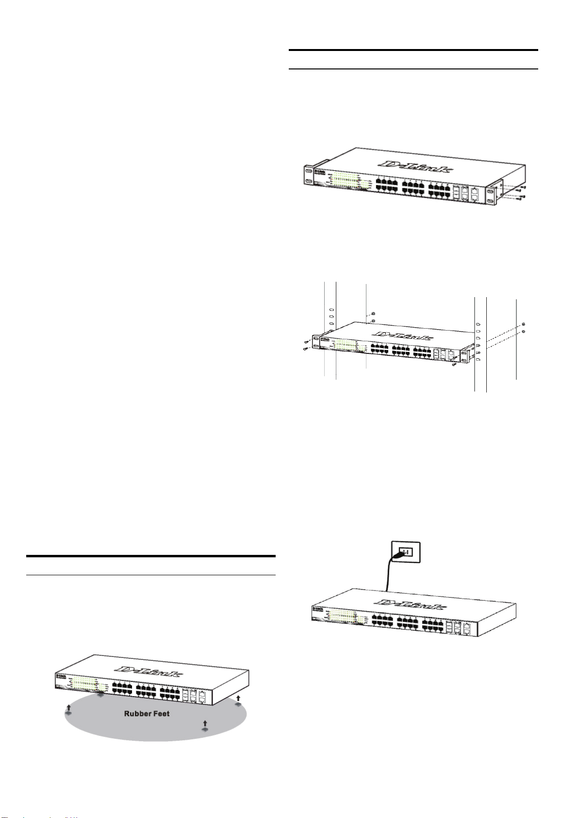
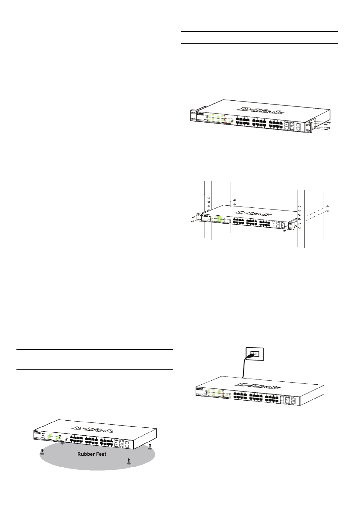
The switch can be mounted in an EIA standard size 19inch rack, which can be placed in a wiring closet with
other equipment. To install, attach the mounting brackets
to the switch’s side panels (one on each side) and
secure them with the screws provided.
Figure 2. Attaching the mounting brackets
Then, use the screws provided with the equipment rack
to mount the switch in the rack.
Step 2 – Switch Installation
For safe switch installation and operation, it is
recommended that you:
Visually inspect the power cord to see that it is
secured fully to the AC power connector
Make sure that there is proper heat dissipation and
adequate ventilation around the switch
Do not place heavy objects on the switch
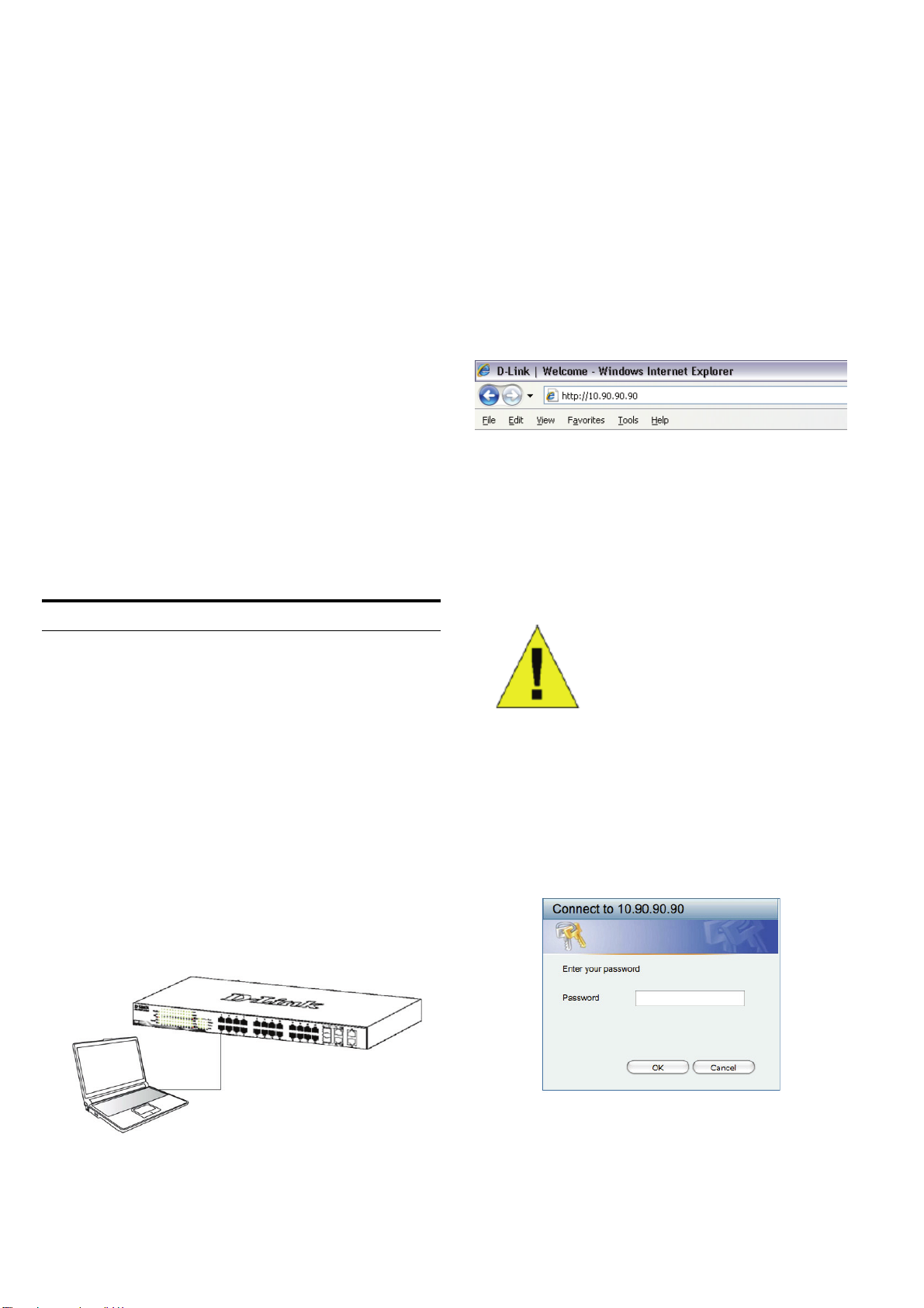
Desktop or Shelf Installation
When installing the switch on a desktop or shelf, the
rubber feet included with the device must be attached on
the bottom at each corner of the device’s base. Allow
enough ventilation space between the device and the
objects around it.
Figure 3. Installing the switch in a standard-sized
equipment rack
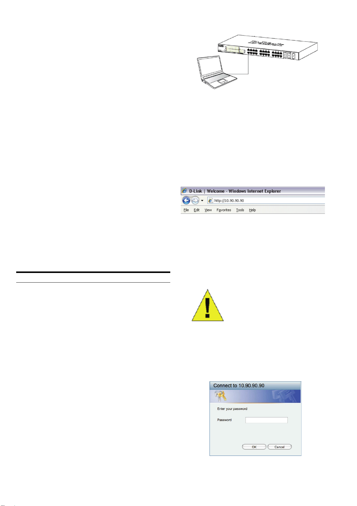
Step 3 – Plugging in the AC
Power Cord
You can now connect the AC power cord into the rear of
the switch and to an electrical outlet (preferably one that
is grounded and surge protected).
Figure 4. Plugging the switch into an outlet
Power Failure
Figure 1. Attaching the rubber feet
As a precaution, the switch should be unplugged in case
of power failure. When power is resumed, plug the switch
back in.
2

Management Options
The D-Link Web Smart Switch can be managed in-band
by using Telnet. The user may also choose the Web-
based Management, accessible through a web browser
or through any PC using the SmartConsole Utility.
If you want to manage only one D-Link Web Smart
Switch, the Web-Based Management is the better option.
Each switch must be assigned its own IP Address, which
is used for communication with Web-Based Management
or an SNMP network manager and the PC should have
an IP address in the same range as the switch.
However, if you want to manage multiple D-Link Web
Smart Switches, the SmartConsole Utility is the better
option. Using the SmartConsole Utility, you don’t need to
change the IP address of your PC and it is easy to start
the initial setting of multiple Smart Switches.
Please refer to the following detailed installation
instructions for the Web-Based Management,
SmartConsole Utility, Telnet Management and SNMPBased Management.
Web-based Management Interface
Step 2
In order to login and configure the switch via an Ethernet
connection, the PC must have an IP address in the same
range as the switch. For example, if the switch has an IP
address of 10.90.90.90, the PC should have an IP
address of 10.x.y.z (where x/y is a number between 0 ~
254 and z is a number between 1 ~254), and a subnet
mask of 255.0.0.0.
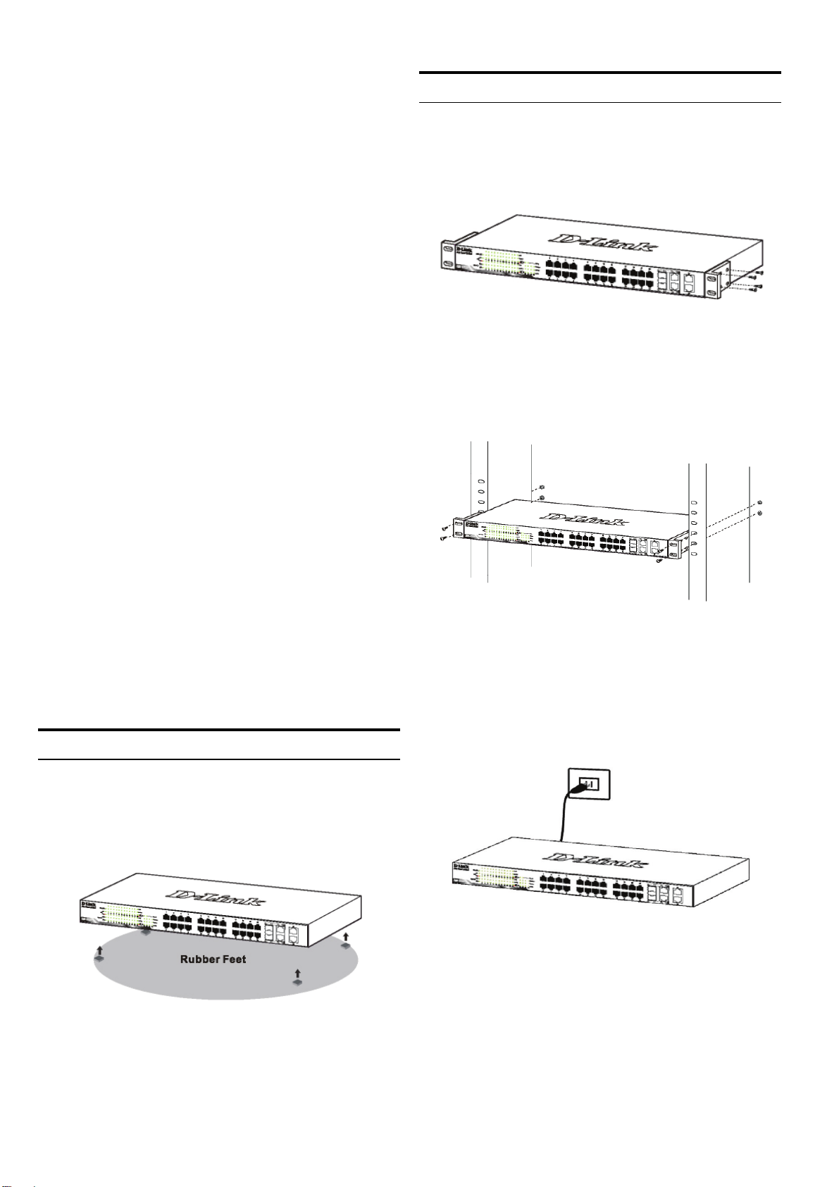
Open your web browser and enter http://10.90.90.90
(the factory-default IP address) in the address box. Then
press <Enter>.
Figure 7. Enter the IP address 10.90.90.90 in the web
browser
The web configuration can also be accessed through the
SmartConsole Utility. Open the SmartConsole Utility
and double-click the switch as it appears in the Device
List. This will automatically load the web configuration in
your web browser.
After a successful physical installation, you can configure
the switch, monitor the LED panel, and display statistics
graphically using a web browser, such as Netscape
Navigator (version 6.2 and higher) or Microsoft
Explorer (version 5.0 and higher).
You need the following equipment to begin the web
configuration of your device:
A PC with a RJ-45 Ethernet connection
A standard Ethernet cable
®
Internet
Step 1
Connect the Ethernet cable to any of the ports on the
front panel of the switch and to the Ethernet port on the
PC.
NOTE: The switch's factory
default IP address is 10.90.90.90
with a subnet mask of 255.0.0.0
and a default gateway of 0.0.0.0
Step 3
When the following logon box appears, enter “admin” for
the password. Press OK to enter the main configuration
window.
Figure 8. User authentication window
Figure 6. Connected Ethernet cable
3

Step 4
Before entering the Web-based Management, the
Smart Wizard will guide you to quickly configure some
functions, such as Password Settings, SNMP Settings,
and System Settings. If you don’t plan to change
anything, click Exit to exit the Wizard and enter the Webbased Management. For a detailed look at the Smart
Wizard’s functions, please refer to the Smart Wizard
introduction in the user manual.
SmartConsole Utility
The SmartConsole Utility included on the installation CD
is a program for discovering Smart Switches with the
same L2 network segment connected to your PC. This
tool is only for computers running Windows 2000,
Windows XP, and Windows Vista x64/86 operating
systems. There are two options for the installation of
SmartConsole Utility, one is through the autorun program
on the installation CD and the other is manual installation.
6. Just connect the Smart Switch to the same L2
network segment of your PC and use the
SmartConsole Utility to discover the Smart
Switches.
For a detailed look at SmartConsole’s functions, please
refer to the SmartConsole Utility introduction in the user
manual.
Telnet Management
Users may also access the switch through Telnet using
your PC’s Command Prompt. To access it from your
computer, users must first ensure that a valid connection
is made through the Ethernet port of the Switch and your
PC, and then click Start > Programs > Accessories >
Command Prompt on your computer. Once the console
window opens, enter the command telnet 10.90.90.90
(depending on configured IP address) and press Enter
on your keyboard. You should be directed to the opening
console screen for the Command Line Interface of the
switch, enter the “admin” for the default user name and
password for the Switch and press the Enter key.
Note: Please be sure to remove any existing
SmartConsole Utility from your PC before installing the
latest SmartConsole Utility.
Option 1: Follow these steps to install the
SmartConsole Utility via the autorun program on the
installation CD.
1. Insert the Utility CD into your CD-Rom Drive.
2. The autorun program will pop up automatically
3. Simply click on the ”Install SmartConsole Utility”
button and an installation wizard will guide you
through the process.
4. After successfully installing the SmartConsole Utility,
you can open the utility by clicking Start > Programs
> D-Link SmartConsole Utility.
5. Just connect the Smart Switch to the same L2
network segment of your PC and use the
SmartConsole Utility to discover the Smart
Switches.
Option 2: Follow these steps to install the
SmartConsole Utility manually.
SNMP-Based Management
You can manage the Switch with D-Link D-View or any
SNMP-compatible program. The SNMP function is
default Disabled for D-Link Web Smart switches.
Additional Information
If you are encountering problems setting up your network,
please refer to the user manual that came with the switch.
It contains many more rules, charts, explanations, and
examples to help you get your network up and running.
Additional help is available through our offices listed at
the back of the user manual or online. To find out more
about D-Link products or marketing information, please
visit the website http://www.dlink.com.tw; for any support
issue, please visit the website http://support.dlink.com.tw,
which will re-direct you to appropriate local D-Link
website.
1. Insert the Utility CD into your CD-Rom Drive.
2. From the Start
choose Run.
3. In the Run dialog box, type D:\D-Link
SmartConsole Utility\setup.exe (where D:\
represents the drive letter of your CD-Rom) and
click OK.
4. Follow the on-screen instructions to install the utility.
5. Upon completion, go to
SmartConsole Utility and open the SmartConsole
Utility.
menu on the Windows desktop,
Start > Programs > D-Link
4

5

Über dieses Handbuch
Abbildung 1: Gummifüße anbringen
Diese Kurzanleitung für die Installation hilft Ihnen Schritt
für Schritt bei der Inbetriebnahme aller Web Smart
Switches von D-Link. Bitte beachten Sie, dass das von
Ihnen erworbene Modell im äußeren Erscheinungsbild
leicht von den in den Illustrationen abgebildeten
Modellen abweichen kann.
Einzelheiten über Ihr Gerät, seine Komponenten, das
Einrichten von Netzwerkverbindungen sowie die
technischen Daten können Sie dem mitgelieferten
Benutzerhandbuch entnehmen.
Schritt 1 – Auspacken
Öffnen Sie die Transportverpackung, und entnehmen Sie
vorsichtig den Inhalt. Vergewissern Sie sich anhand der
Packliste im Benutzerhandbuch, dass alle Bestandteile
vollständig und unbeschädigt vorhanden sind. Sollte
eines der Teile fehlen oder beschädigt sein, wenden Sie
sich bitte an Ihren D-Link-Fachhändler.
- Ein D-Link Web Smart Switch
- Einbauwinkel
- Stromkabel
Rackmontage
Der Switch kann in einem 19-Zoll-Rack (EIAStandardgröße) montiert und mit weiteren Geräten in
einem Verkabelungsschrank installiert werden. Bringen
Sie an jedem Seitenblech des Switch einen Einbauwinkel
an, und schrauben Sie die Winkel mit den beiliegenden
Schrauben fest.
Montieren Sie danach den Switch im Einschub mit den
Schrauben, die Sie zu Ihrem Rack erhalten haben.
Abbildung 2: Einbauwinkel anbringen
- CD-ROM mit Benutzerhandbuch und dem
Dienstprogramm SmartConsole
- Eine Kurzanleitung in mehreren Sprachen
Schritt 2 – Switch installieren
Gehen Sie zum sicheren Installieren und Betreiben des
Switch wie folgt vor:
Vergewissern Sie sich, dass das Stromkabel
unbeschädigt ist, und achten Sie auf den festen
Sitz der Steckverbindungen.
Sorgen Sie für eine funktionierende
Wärmeableitung und eine ausreichende Belüftung
in der Umgebung des Switch.
Stellen Sie keine schweren Gegenstände auf den
Switch.
Tisch- oder Regalmontage
Wenn Sie den Switch auf einem Tisch oder in einem
Regal aufstellen möchten, bringen Sie vorher die
mitgelieferten Gummifüße in den vier Ecken an der
Unterseite des Gehäuses an. Lassen Sie um das Gerät
herum genug Platz zur Belüftung frei.
Abbildung 3: Switch im Standardrack installieren
Schritt 3 – An die
Stromversorgung anschließen
Schließen Sie das Stromkabel an eine Steckdose
(möglichst geerdet und mit Überspannungsschutz) und
an den Netzanschluss auf der Rückseite des Switch an.
Abbildung 4: Switch an die Stromversorgung anschließen
Stromausfall
Aus Sicherheitsgründen sollten Sie bei einem
Stromausfall den Netzstecker ziehen. Ist die
Stromversorgung wieder gewährleistet, können Sie den
Netzstecker des Switch wieder einstecken.
6

Verwaltungsoptionen
Mithilfe von Telnet ist ein In-Band-Management des Web
Smart Switch von D-Link möglich. Sie können aber auch
das webbasierte Management wählen, auf das Sie über
einen Webbrowser oder über jeden PC zugreifen können,
der die SmartConsole Utility verwendet.
Wenn Sie nur einen D-Link Web Smart Switch verwalten
möchten, eignet sich dafür am besten die webbasierte
Verwaltungsoberfläche. Jedem Switch muss eine eigene
IP-Adresse zugewiesen werden, die für die
Kommunikation mit dem webbasierten
Verwaltungsprogramm oder einem SNMPNetzwerkmanager verwendet wird. Die IP-Adresse des
PC sollte im gleichen Bereich liegen wie die des Switch.
Wenn Sie mehrere D-Link Web Smart Switches
verwalten möchten, verwenden Sie am besten das
Dienstprogramm SmartConsole. In diesem Fall
brauchen Sie die IP-Adresse Ihres PC nicht zu ändern
und die Ersteinstellung mehrerer Smart Switches kann
auf einfache Weise vorgenommen werden.
In den folgenden Abschnitten dieser Anleitung finden Sie
detaillierte Informationen zum webbasierten
Verwaltungsprogramm und zum Dienstprogramm
SmartConsole, Telnet-Management und SNMP-
basiertes Management.
Die webbasierte Management-Benutzeroberfläche
Schritt 2
Zur Anmeldung und um den Switch über eine EthernetVerbindung zu konfigurieren, muss der PC eine IPAdresse im gleichen Adressenbereich wie der Switch
aufweisen. Beispiel: Wenn der Switch die IP-Adresse
10.90.90.90 hat, sollte der PC die IP-Adresse 10.x.y.z
haben (wobei x/y eine Zahl zwischen 0 ~ 254 und z eine
zwischen 1 ~254 ist) und eine Subnetzmaske 255.0.0.0.
Öffnen Sie Ihren Webbrowser, und geben Sie
http://10.90.90.90 (die werkseitige Standard-IP-Adresse)
in die Adresszeile ein. Drücken Sie anschließend die
Eingabetaste.
Abbildung 7: IP-Adresse 10.90.90.90 in den Webbrowser
Die Webkonfiguration kann auch über das
Dienstprogramm SmartConsole vorgenommen werden.
Öffnen Sie SmartConsole, und doppelklicken Sie in der
Geräteliste auf den Switch. Daraufhin wird die
Webkonfiguration automatisch in Ihrem Webbrowser
geladen.
eingeben
Nach erfolgreicher Installation können Sie den Switch
konfigurieren, die LED-Anzeigen überwachen und
Statistiken grafisch über einen Webbrowser anzeigen
lassen, z. B. mit Netscape Navigator (Version 6.2 und
höher) oder Microsoft
höher).
Sie benötigen das folgende Zubehör, um mit der
Webkonfiguration Ihres Geräts zu beginnen:
Einen PC mit einem RJ-45-Ethernet-Anschluss
Ein Standard-Ethernetkabel
®
Internet Explorer (Version 5.0 und
Schritt 1
Verbinden Sie das Ethernetkabel mit einem beliebigen
Anschluss auf der Vorderseite des Switch und mit dem
Ethernetanschluss an Ihrem PC.
HINWEIS: Die werkseitige Standard-IPAdresse des Switch lautet 10.90.90.90, die
Subnetzmaske 255.0.0.0 und das
Standard-Gateway 0.0.0.0
Schritt 3
Wenn der folgende Anmeldedialog angezeigt wird,
geben Sie „admin“ als Kennwort ein. Klicken Sie
anschließend auf OK.
Abbildung 8: Benutzerauthentifizierung
Schritt 4
Bevor Sie jedoch das webbasierte Management
Abbildung 6: Ethernetkabel anschließen
verwenden, gibt Ihnen der Assistent (Smart Wizard)
7

Anleitungen zur schnellen Konfiguration einiger
Funktionen, wie zum Einrichten von Kennwörtern
(Password Settings), den SNMP-Einstellungen (SNMP
Settings) und den Systemeinstellungen (System
Settings). Wenn Sie keine Änderungen geplant haben,
klicken Sie auf Exit (Beenden), um den Assistenten zu
beenden und auf die webbasierte ManagementBenutzeroberfläche zuzugreifen. Genaue
Beschreibungen der Funktionen des Assistenten finden
Sie in der Einführung zum Smart Wizard im
Benutzerhandbuch.
SmartConsole
Das Dienstprogramm SmartConsole befindet sich auf der
Installations-CD und ist ein Programm zur Suche von
Smart Switches mit dem gleichen L2-Netzwerksegment,
mit dem Ihr PC verbunden ist. Dieses Tool läuft nur auf
Computern mit dem Betriebssystem Windows 2000,
Windows XP oder Windows Vista x64/86. Sie können
SmartConsole auf zwei Arten installieren: über das
Installationsprogramm auf der Installations-CD oder
manuell.
Hinweis: Falls auf Ihrem Computer bereits eine Version
von SmartConsole installiert ist, müssen Sie diese
deinstallieren, bevor Sie die neueste Version von
SmartConsole installieren können.
1. Option: Führen Sie die folgenden Schritte durch,
um SmartConsole über das auf der Installations-CD
vorhandene Installationsprogramm zu installieren.
1. Legen Sie die CD in das CD-ROM-Laufwerk ein.
2. Das Installationsprogramm wird automatisch geöffnet.
3. Klicken Sie auf die Schaltfläche Install
SmartConsole Utility (SmartConsole installieren).
Der daraufhin angezeigte Installationsassistent wird
Sie durch den Installationsvorgang führen.
4. Nachdem Sie SmartConsole erfolgreich installiert
haben, können Sie das Dienstprogramm über Start
> Programs (Programme) > D-Link SmartConsole
Utility öffnen.
5. Schließen Sie den Smart Switch an das gleiche L2Netzwerksegment Ihres PC an, und führen Sie mit
SmartConsole eine Suche nach Smart Switches
durch.
2. Option: Führen Sie die folgenden Schritte durch,
um das Dienstprogramm SmartConsole manuell zu
installieren.
1. Legen Sie die CD in das CD-ROM-Laufwerk ein.
2. Klicken Sie unter Windows im Menü Start auf Run
(Ausführen).
3. Geben Sie im Dialogfeld Run (Ausführen)
folgende Befehlszeile ein: D:\SmartConsole
Utility\setup.exe (hierbei steht „D:“ für den
Laufwerksbuchstaben Ihres CD-ROM-Laufwerks).
Klicken Sie anschließend auf OK.
4. Befolgen Sie die Installationsanweisungen auf dem
Bildschirm.
5. Klicken Sie nach Abschluss der Installation zum
Starten des Dienstprogramms SmartConsole auf
Start -> Programs (Programme) -> SmartConsole
Utility.
6. Schließen Sie den Smart Switch an das gleiche L2Netzwerksegment Ihres PC an, und führen Sie mit
SmartConsole eine Suche nach Smart Switches
durch.
Weitere Informationen zu den Funktionen von
SmartConsole finden Sie im Benutzerhandbuch in der
Einführung zu SmartConsole.
Das Telnet-Management
Zugriff auf den Switch ist auch über Telnet mithilfe der
Eingabeaufforderungsfunktion Ihres PCs möglich. Dazu
müssen Sie zunächst sicherstellen, dass über den
Ethernet-Port des Switches und Ihrem PC eine
Verbindung besteht. Klicken Sie dann auf Ihrem
Computer auf Start > Programme > Zubehör>
Eingabeaufforderung. Sobald das Console-Fenster
geöffnet ist, geben Sie den Befehl telnet 10.90.90.90
(abhängig von der konfigurierten IP-Adresse) ein und
drücken Sie auf die Eingabetaste auf Ihrer Tastatur.
Damit wird das Hauptfenster der Console für die
Befehlszeilen-Schnittstelle geöffnet. Geben Sie dort
“admin” als standardmäßig vorgegebenen
Benutzernamen und als Kennwort für den Switch ein und
drücken Sie auf die Eingabetaste.
Das SNMP-basierte Management
Die Verwaltung des Switches ist auch mit D-View von DLink oder jedem SNMP-kompatiblen Programm möglich.
Die SNMP-Funktion ist jedoch standardmäßig für Web
Smart Switches von D-Link deaktiviert.
Ergänzende Hinweise
Falls es bei der Konfiguration des Netzwerks Probleme
gibt, schlagen Sie am besten zuerst im
Benutzerhandbuch nach. Es enthält zusätzliche
Richtlinien, Abbildungen, Erklärungen und Beispiele, die
Sie bei Aufbau und Inbetriebnahme Ihres Netzwerks
unterstützen.
Weitere Hilfe erhalten Sie im Internet oder bei unseren
Niederlassungen, die auf der Rückseite des
Benutzerhandbuchs aufgelistet sind. Für weitere
Informationen zu den Produkten von D-Link sowie
Marketing-Informationen besuchen Sie die Website
http://www.dlink.eu. Bei Support-Fragen gehen Sie
ebenfalls auf diese Website http://support.dlink.com.tw.
Hier werden Sie dann auf die entsprechende lokale DLink-Seite geleitet.
8

9

À propos de ce guide
Installation dans une armoire
Ce guide vous explique, étape par étape, comment
configurer tous les Smart Switches Web de D-Link.
Remarque : il se peut que votre modèle d’appareil diffère
légèrement de ceux illustrés dans le présent manuel.
Pour obtenir des informations plus détaillées sur votre
switch, ses composants, ses connexions réseau et ses
spécifications techniques, reportez-vous au Guide de
l’utilisateur fourni dans son emballage.
Étape 1 : déballage
Ouvrez le carton d’expédition et sortez-en le contenu
avec précaution. Le Guide de l’utilisateur contient une
liste des éléments devant se trouver dans l’emballage ;
en vous y reportant, vérifiez que tous les composants
sont présents et en parfait état. Si un élément est absent
ou détérioré, contactez votre revendeur D-Link pour en
obtenir un nouveau.
- Un Smart Switch Web D-Link
- Un support pour montage en armoire
- Un cordon d’alimentation
- Le CD du Guide de l’utilisateur, incluant l’utilitaire
SmartConsole
Vous pouvez monter votre switch dans une armoire
19 pouces EIA standard, à insérer dans une armoire de
câblage avec d’autres équipements. Pour cela, installez
les supports sur les panneaux latéraux du switch (un de
chaque côté) et fixez-les à l’aide des vis fournies.
Figure 2. Fixation des supports de montage
Utilisez ensuite les vis fournies pour monter le switch
dans l’armoire.
- Un guide de démarrage multilingue
Étape 2 : installation du switch
Pour installer et utiliser le switch en toute sécurité, nous
vous recommandons de procéder comme suit :
Inspectez le cordon d’alimentation et assurez-vous
qu’il est parfaitement relié au connecteur
d’alimentation secteur.
Vérifiez que le switch présente une dissipation de
chaleur adaptée et qu’il est entouré d’un espace
suffisant pour garantir une bonne ventilation.
Ne posez pas d’objets lourds sur le switch.
Installation sur un bureau ou sur une
étagère
Pour installer le switch sur un bureau ou une étagère,
vous devez ajouter les pieds en caoutchouc fournis aux
quatre coins de sa base. À des fins de ventilation,
prévoyez un espace suffisant entre l’appareil et les
objets environnants.
Figure 3. Installation du switch dans une armoire de taille
standard
Étape 3 : raccordement au
secteur
À présent, reliez le switch à une prise de courant (de
préférence mise à la terre et dotée d’un parasurtenseur)
à l’aide du cordon d’alimentation secteur branché à
l’arrière du switch.
Figure 4. Raccordement du switch à une prise de courant
Panne de courant
En cas de panne de courant, par précaution, débranchez
le switch. Rebranchez-le une fois le courant rétabli.
Pieds en caoutchouc
Figure 1. Fixation des pieds en caoutchouc
10

Options d’administration
Le commutateur Web intelligent D-Link peut être géré
intrabande via Telnet. L'utilisateur peut aussi choisir
l'interface de gestion Web, accessible par
l'intermédiaire d'un navigateur Web ou de n'importe quel
PC utilisant l'utilitaire SmartConsole.
Si vous ne souhaitez administrer qu’un seul Smart
Switch Web D-Link, nous vous recommandons l’utilitaire
de gestion Web. Chaque switch doit disposer de sa
propre adresse IP pour communiquer avec l’utilitaire de
gestion Web ou un gestionnaire de réseau SNMP. Par
ailleurs, le PC doit être associé à une adresse IP
comprise dans la même plage que celle du switch.
Cependant, si vous souhaitez gérer plusieurs Smart
Switches Web D-Link, l’utilitaire SmartConsole est la
meilleure solution. Grâce à l’utilitaire SmartConsole,
vous n’avez plus besoin de changer l’adresse IP de votre
PC et la configuration initiale de Smart Switches
multiples est plus simple à lancer.
Pour savoir comment installer les utilitaires de gestion
Web et SmartConsole, veuillez consulter les
instructions détaillées suivantes, Interface de gestion
Telnet et interface de gestion SNMP.
Interface de gestion Web
Étape 2
Pour pouvoir ouvrir une session et configurer le
commutateur via une connexion Ethernet, l'adresse IP du
PC doit être dans la même plage que celle du
commutateur. Par exemple, si l'adresse IP du
commutateur est 10.90.90.90, l'adresse IP du PC doit
être 10.x.y.z (où x et y sont compris entre 0 et 254 et z
est compris entre 1 et 254) et son masque de sousréseau doit être 255.0.0.0.
Ouvrez votre navigateur Web et, dans la barre d’adresse,
tapez http://10.90.90.90 (adresse IP par défaut). Ensuite,
appuyez sur <Entrée>.
Figure 7. Saisie de l’adresse IP 10.90.90.90 dans le
Vous pouvez également accéder à la configuration Web
via l’utilitaire SmartConsole. Ouvrez l’utilitaire
SmartConsole et, dans la liste des switches, doublecliquez sur celui de votre choix. La configuration Web est
automatiquement chargée dans votre navigateur Web.
navigateur Web
Une fois l’installation physique effectuée, vous pouvez
configurer le switch, surveiller les voyants et afficher des
graphiques de statistiques à l’aide d’un navigateur Web
(Netscape Navigator version 6.2 ou supérieure, ou
Microsoft® Internet Explorer version 5.0 ou supérieure,
par exemple).
Pour commencer la configuration Web de votre unité,
vous avez besoin des éléments suivants :
PC équipé d’une connexion Ethernet RJ-45
Câble Ethernet standard
Étape 1
Connectez une extrémité du câble Ethernet à l’un des
ports disponibles sur le panneau avant du switch et
l’autre extrémité au port Ethernet de l’ordinateur.
REMARQUE : L’adresse IP par
défaut du switch est 10.90.90.90 ; son
masque de sous-réseau est 255.0.0.0
et sa passerelle par défaut, 0.0.0.0
Étape 3
Lorsque la boîte de connexion suivante apparaît, entrez
le mot de passe « admin ». Appuyez sur OK pour ouvrir
la fenêtre de configuration principale.
Figure 8. Fenêtre d’authentification utilisateur
Figure 6. Branchement du câble Ethernet
11

Étape 4
Avant d'accéder à l'interface de gestion Web,
l'assistant intelligent vous aidera à configurer
rapidement certaines fonctions, telles que le mot de
passe, les paramètres SNMP et les paramètres
système. Si vous n'envisagez aucune modification,
cliquez sur Quitter pour fermer l'assistant et accéder à
l'interface de gestion Web. Pour une description détaillée
des fonctions de l'assistant intelligent, consultez la
présentation qui lui est consacrée dans le manuel
d'utilisation.
4. Pour installer l’utilitaire, suivez les instructions
affichées à l’écran.
5. Une fois l’installation terminée, sélectionnez
Démarrer > Tous les programmes > D-Link
SmartConsole Utility (Utilitaire D-Link
SmartConsole), puis lancez l’utilitaire
SmartConsole
6. Connectez le Smart Switch au même segment de
réseau de niveau 2 que le PC et détectez les Smart
Switches présents via l’utilitaire SmartConsole.
Pour une présentation détaillée des fonctions de
l’utilitaire SmartConsole, consultez la présentation qui lui
est consacrée dans le Guide de l’utilisateur.
.
Utilitaire SmartConsole
L’utilitaire SmartConsole est inclus dans le CD
d’installation. Il s’agit d’un programme de détection des
Smart Switches connectés au même segment de réseau
de niveau 2 que le PC. Cet outil concerne uniquement
les PC exécutant Windows 2000, Windows XP et
Windows Vista x64/86. Vous pouvez procéder de deux
manières pour installer cet utilitaire : en lançant le
programme d’installation automatique présent sur le CD
ou manuellement.
Remarque : avant d’installer la dernière version de
l’utilitaire SmartConsole, veillez à supprimer toute
installation précédente.
Option 1 : la procédure suivante vous permet
d’installer l’utilitaire SmartConsole via le programme
d’installation automatique du CD.
1. Insérez le CD de l’utilitaire dans le lecteur de CDROM.
2. Le programme d’installation automatique apparaît.
3. Cliquez sur le bouton “Install SmartConsole Utility”
(Installer l’utilitaire SmartConsole). Un assistant vous
guidera tout au long du processus.
4. Une fois l’utilitaire installé, ouvrez-le en cliquant sur
Démarrer > Tous les programmes > D-Link
SmartConsole Utility (Utilitaire D-Link
SmartConsole).
5. Connectez le Smart Switch au même segment de
réseau de niveau 2 que le PC et détectez les Smart
Switches présents via l’utilitaire SmartConsole.
Option 2 : la procédure suivante vous permet
d’installer l’utilitaire SmartConsole manuellement.
1. Insérez le CD de l’utilitaire dans le lecteur de CD-
ROM.
2. Dans le menu Démarrer du bureau Windows,
choisissez Exécuter
3. Dans la boîte de dialogue Exécuter, tapez D:\D-
Link SmartConsole Utility\setup.exe (où D:\
correspond à votre lecteur de CD-ROM), puis
cliquez sur OK.
.
Interface de gestion Telnet
Vous pouvez également accéder au commutateur via Telnet au
moyen d'une invite de commande du PC Pour y accéder depuis
l'ordinateur, commencez par vous assurer qu'une connexion
valable est établie entre le port Ethernet du commutateur et le
PC, puis sur ce dernier cliquez sur Démarrer > Programmes >
Accessoires > Invite de commandes. Dans la fenêtre de la
console qui s'ouvre, entrez la commande telnet 10.90.90.90
(selon l'adresses IP configurée), puis appuyez sur la touche
Entrée du clavier. Vous devriez alors accéder à l'écran de la
console pour l'interface de ligne de commande du commutateur.
Entrez « admin » comme nom d'utilisateur et mot de passe par
défaut du commutateur, puis appuyez sur Entrée.
Interface de gestion SNMP
Vous pouvez gérer le commutateur à l'aide de D-Link DView ou de n'importe quel programme SNMP compatible.
La fonction SNMP est désactivée par défaut pour les
commutateurs Web intelligents D-Link.
Informations supplémentaires
Si vous rencontrez des problèmes lors de la
configuration du réseau, reportez-vous au Guide de
l’utilisateur fourni avec le switch. Il contient un grand
nombre d’instructions, de croquis, d’explications et
d’exemples pour vous aider à installer votre réseau.
Vous trouverez également une aide supplémentaire
auprès de nos bureaux indiqués au dos du Guide de
l’utilisateur ou en ligne. Pour en savoir plus sur les
produits D-Link et pour toute information d’ordre
marketing, visitez notre site Web à l’adresse
http://www.dlink.eu. Pour une aide technique, visitez le
site Web à l’adresse http://support.dlink.com.tw, qui vous
redirigera vers votre site Web D-Link local.
12

13
Sobre esta guía
Instalación en rack
Esta guía ofrece las instrucciones detalladas para
configurar todos los switches Web Smart de D-Link.
Tenga en cuenta que el modelo que ha comprado puede
ser algo diferente al que se muestra en las ilustraciones.
Si desea más información sobre el switch, sus
componentes, la manera de realizar las conexiones de
red o las especificaciones técnicas, consulte la Guía del
usuario que se incluye con el switch.
Paso 1. Desempaquetar
Abra la caja y con cuidado saque el contenido. Consulte
la lista de componentes en la Guía del usuario para
asegurarse de que están todos los elementos y que se
encuentran en perfecto estado. Si falta algún
componente o ha sufrido algún daño, contacte con su
distribuidor de D-Link para que se lo cambie.
- Un switch Web Smart de D-Link.
- Ángulo para montaje en rack.
- Cable de alimentación
- CD con la Guía del usuario y el programa
SmartConsole.
El switch se puede montar en un rack EIA estándar de
19'', que se puede colocar en un armario de cableado
junto a otros equipos. Para instalarlo, fije los ángulos de
montaje en los laterales del switch (uno a cada lado)con
los tornillos suministrados.
Figura 2. Fijar los ángulos de montaje
Luego, con los tornillos suministrados con el rack, monte
el switch en el rack.
- Una Guía de iniciación multilingüe.
Paso 2. Instalación del switch
Para que la instalación y el funcionamiento del switch
sean seguros, se recomienda que:
Inspeccione visualmente el cable de alimentación
para comprobar que está correctamente
conectado al conector de alimentación AC.
Se asegure de que, alrededor del switch, el calor
se disipa correctamente y se ventila
adecuadamente.
No sitúa objetos pesados sobre el switch.
Instalación de sobremesa o en estante
Para instalar el switch sobre una mesa o en un estante,
debe fijar los pies de goma que se incluyen con el
dispositivo en la base del mismo, uno en cada esquina.
Deje suficiente espacio entre el dispositivo y los objetos
que haya alrededor para la ventilación.
Figura 3. Instalar el switch en un rack estándar
Paso 3. Conexión del cable de
alimentación AC
Ahora puede conectar el cable de alimentación AC a la
parte posterior del switch y a una toma eléctrica
(preferiblemente una que disponga de toma de tierra y
protector de sobretensión).
Figura 4. Conectar el switch a una toma eléctrica
Corte del suministro eléctrico
Como precaución, en caso de corte del suministro
eléctrico, el switch debería desenchufarse. Cuando se
restablece el consumo eléctrico, puede volver a
enchufarlo.
Figura 1. Fijar los pies de goma
14

Opciones de gestión
El switch Web Smart de D-Link puede gestionarse a
través de cualquier puerto del dispositivo usando la
utilidad de gestión basada en web, o bien a través de
cualquier PC usando la utilidad SmartConsole.
Si quiere gestionar solo un switch Web Smart de D-Link,
la mejor opción es la utilidad de gestión basada en web.
Cada switch debe tener asignada su propia dirección IP,
que se usa para comunicarse con la utilidad de gestión
basada en web o con un gestor de red SNMP, y el PC
ha de tener una dirección IP en el mismo rango que el
switch.
Sin embargo, si quiere gestionar varios switches Web
Smart de D-Link, la mejor opción es la utilidad
SmartConsole. Con la utilidad SmartConsole, no
necesita cambiar la dirección IP del PC y es fácil realizar
la configuración inicial de varios switches Smart.
Vea las instrucciones detalladas que figuran a
continuación sobre la utilidad de gestión basada en
web y la utilidad SmartConsole, Gestión de Telnet y
gestión basada en SNMP.
Paso 2
Para iniciar sesión y configurar el switch a través de una
conexión Ethernet, el PC debe tener una dirección IP en
el mismo rango que el switch. Por ejemplo, si el switch
tiene una dirección IP de 10.90.90.90, el PC debe tener
una dirección IP de 10.x.y.z (donde x/y es un número
entre 0 y 254 y z es un número entre 1 y 254), y una
máscara de subred de 255.0.0.0.
Abra el navegador web y escriba http://10.90.90.90 (la
dirección IP por defecto) en el campo de direcciones.
Luego pulse <Intro>.
Figura 7. Introducir la dirección IP 10.90.90.90 en el
navegador web
A la configuración web también se puede acceder a
través de la utilidad SmartConsole. Abra la utilidad
SmartConsole y haga doble clic sobre el switch, que
figura en la lista de dispositivos. De este modo, se
cargará la configuración web en el navegador web.
Interfaz de gestión basada en web
Tras haber realizado la instalación física sin problemas,
puede configurar el switch, controlar el panel de
indicadores LED y visualizar las estadísticas
gráficamente por medio de un navegador web, como
Netscape Navigator (versión 6.2 o superior) o Microsoft
Internet Explorer (versión 5.0 o superior).
Para realizar la configuración web del dispositivo,
necesita el equipo siguiente:
Un PC con una conexión Ethernet RJ-45.
Un cable Ethernet estándar.
Paso 1
Conecte el cable Ethernet a cualquiera de los puertos
del panel delantero del switch y al puerto Ethernet del
PC.
NOTA: La dirección IP por
defecto del switch es
10.90.90.90, con una máscara
de subred de 255.0.0.0 y un
®
gateway por defecto de 0.0.0.0
Paso 3
Cuando aparezca la siguiente caja de entrada al sistema,
escriba «admin» en el campo contraseña. Pulse OK
para entrar en la ventana principal de configuración.
Figura 8. Ventana de autentificación del usuario
Paso 4
Figura 6. Conectar el cable Ethernet
Antes de acceder a la gestión basada en web, el
Asistente inteligente le guiará para configurar
15

rápidamente algunas funciones como Parámetros de
contraseña, Parámetros de SNMP y Parámetros del
sistema. Si no tiene previsto cambiar nada, haga clic en
Salir para salir del asistente y entrar en la gestión
basada en web. Para ver detalladamente las funciones
del Asistente inteligente, consulte la introducción al
Asistente inteligente en el manual de usuario.
6. Conecte el switch Smart Switch al mismo segmento
de red L2 de su PC y use la utilidad
SmartConsole para detectar los switches Smart.
Si desea más información sobre las funciones de la
utilidad SmartConsole, consulte la introducción a la
utilidad SmartConsole en el Manual del usuario.
Gestión de Telnet
Utilidad SmartConsole
La utilidad SmartConsole incluida en el CD de
instalación es un programa para detectar switches con el
mismo segmento de red L2 conectados a su PC. Esta
herramienta es solo para ordenadores con los sistemas
operativos Windows 2000, Windows XP, y Windows
Vista x64/86. Para la instalación de la utilidad
SmartConsole se dispone de dos opciones: a través del
programa autorun del CD de instalación, o bien del
manual de instalación.
Nota: Asegúrese de que ha eliminado cualquier utilidad
SmartConsole que pudiera haber en su PC antes de
instalar la última versión de la utilidad SmartConsole.
Opción 1: Siga estos pasos para instalar la utilidad
SmartConsole a través del programa autorun del CD
de instalación.
1. Introduzca el CD de la utilidad en la unidad de CDROM.
2. El programa autorun se abrirá automáticamente.
3. Haga clic en el botón «Instalar utilidad
SmartConsole» y un asistente de instalación lo
guiará a lo largo del proceso.
4. Tras haber instalado correctamente la utilidad
SmartConsole, abra la utilidad haciendo clic en
Inicio > Programas > D-Link SmartConsole Utility.
5. Conecte el switch Smart Switch al mismo segmento
de red L2 de su PC y use la utilidad SmartConsole
para detectar los switches Smart.
Opción 2: Siga estos pasos para instalar la utilidad
SmartConsole manualmente.
1. Introduzca el CD de la utilidad en la unidad de CD-
ROM.
2. En el menú Inicio
Ejecutar.
3. En el cuadro de diálogo Ejecutar, escriba «D:\D-
Link SmartConsole Utility\setup.exe» (donde D:\
representa la letra de la unidad de su CD-ROM) y
haga clic en OK.
4. Siga las instrucciones que aparecen en la pantalla
para instalar la utilidad.
5. Tras completarlo, vaya a
Link SmartConsole Utility y abra la utilidad
SmartConsole.
del escritorio de Windows, elija
Inicio > Programas > D-
Los usuarios pueden acceder también al switch a través de
Telnet utilizando el símbolo del sistema del PC. Para acceder
al mismo desde el ordenador, los usuarios deben asegurarse
en primer lugar de que se ha establecido una conexión válida a
través del puerto Ethernet del switch y el PC y, a continuación,
haga clic en Inicio > Programas > Accesorios > Símbolo del
sistema en su ordenador. Una vez abierta la ventana de la
consola, introduzca el comando telnet 10.90.90.90 (en función
de la dirección IP configurada) y pulse Intro en el teclado. El
sistema le dirigirá a pantalla de bienvenida de la consola de la
Interfaz de línea de comandos del switch, introduzca “admin”
para el nombre de usuario y contraseña predeterminado para
el switch y pulse la tecla Intro.
Gestión basada en SNMP
Puede gestionar el switch con el software D-View de DLink o cualquier programa compatible con SNMP. La
función SNMP se desactiva de forma predeterminada
para los Smart Switches D-Link.
Información adicional
Si le surgen problemas al configurar la red, consulte el
Manual del usuario que se adjunta con el switch.
Contiene muchas más reglas, esquemas, explicaciones
y ejemplos que le ayudarán a tener la red lista y en
funcionamiento.
En nuestras oficinas, que figuran al final del Manual del
usuario o en línea, encontrará más ayuda. Si desea más
información sobre los productos de D-Link o sobre
márquetin, visite el sitio web: http://www.dlink.com.tw; si
se requiere asistencia, visite el sitio web:
http://support.dlink.com.tw, que le redirigirá hacia su sitio
web local de D-Link.
16

17

Informazioni sul presente
Installazione su rack
manuale
Il presente manuale rapido d’installazione fornisce le
istruzioni per impostare tutti i Web Smart Switch di DLink. Il modello acquistato potrebbe differire leggermente
da quello riportato nelle illustrazioni.
Maggiori informazioni sullo switch, i suoi componenti, le
connessioni di rete e le specifiche tecniche sono
contenute nel Manuale utente fornito con il prodotto.
Fase 1 – Disimballaggio
Aprire la confezione ed estrarne delicatamente il
contenuto. Verificare il contenuto del pacchetto,
confrontandolo con l’elenco riportato nel manuale utente.
Se un componente dovesse risultare mancante o
danneggiato, contattare il rivenditore D-Link locale per la
sostituzione.
- 1 Web Smart Switch D-Link
- Staffe per montaggio su rack
- Cavo di alimentazione
- CD del Manuale utente con programma SmartConsole
Utility
- 1 manuale rapido di installazione multilingue
Lo switch può essere montato in un rack da 19 pollici,
conforme allo standard EIA, posizionabile in un armadio
elettrico. Fissare le staffe di montaggio ai pannelli laterali
dello switch (una per lato) e fermarle con le viti fornite.
Figura 2. Fissaggio delle staffe di montaggio
Montare lo switch all’interno del rack, utilizzando le viti
fornite con quest’ultimo.
Figura 3. Installazione dello switch all’interno del rack
Fase 2 – Installazione dello
switch
Per una installazione sicura dello switch, si consiglia di:
Ispezionare il cavo di alimentazione e verificare
che sia correttamente fissato al relativo connettore
CA.
Verificare che attorno allo switch ci sia lo spazio
sufficiente per un’adeguata ventilazione e
dissipazione del calore.
Non posizionare oggetti pesanti sopra lo switch.
Installazione su un ripiano o una scrivania
Per installare lo switch su un ripiano o una scrivania,
fissare i piedini in gomma forniti con il dispositivo ai
quattro angoli del pannello inferiore. Per consentire una
corretta ventilazione è necessario lasciare uno spazio
sufficiente tra il dispositivo e gli oggetti circostanti.
Fase 3 – Collegamento del cavo
di alimentazione CA
È ora possibile connettere il cavo di alimentazione CA al
relativo connettore posto sul pannello posteriore dello
switch e a una presa di corrente (preferibilmente dotata
di messa a terra e protezione da sovratensioni).
Figura 4. Collegamento dello switch alla presa di corrente
Interruzione di corrente
Per precauzione, in caso di un’interruzione di corrente si
consiglia di disconnettere lo switch. Riconnettere il
dispositivo quando l’erogazione di corrente elettrica torna
alla normalità.
Figura 1. Fissaggio dei piedini in gomma
18
Opzioni di gestione
Il switch D-Link Web Smart può essere gestito in banda
utilizzando Telnet. Inoltre l’utente può scegliere la
gestione basata sul Web, accessibile tramite browser
web oppure tramite qualunque PC usando la
SmartConsole Utility.
Per la gestione di un unico Web Smart Switch di D-Link,
l'opzione migliore è rappresentata dall'Utility di gestione
basata sul web. Per consentire la comunicazione con
l'Utility di gestione basata sul web o con un gestore di
rete SNMP, è necessario assegnare un indirizzo IP ad
ogni switch. Il PC deve avere un indirizzo IP
appartenente alla stessa gamma di indirizzi IP dello
switch.
Tuttavia, per gestire più di un Web Smart Switch di DLink, la SmartConsole Utility rappresenta l'opzione
migliore. Utilizzando la SmartConsole Utility, non è
necessario modificare l'indirizzo IP del PC e la procedura
iniziale di configurazione risulta notevolmente
semplificata.
Consultare le seguenti istruzioni sull'utilizzo dell'Utility di
gestione basata sul web e della SmartConsole Utility,
Gestione Telnet e gestione basata su SNMP.
Fase 2:
Per poter effettuare l'accesso e configurare lo switch
tramite una connessione Ethernet, gli indirizzi IP del PC
e dello switch devono essere compresi nello stesso
intervallo. Ad esempio, se l'indirizzo IP dello switch è
10.90.90.90, l'indirizzo IP del PC deve essere 10.x.y.z
(dove x/y è un numero compreso tra 0 e 254 e z è un
numero compreso tra 1 e 254), mentre la subnet mask
deve essere 255.0.0.0.
Aprire il browser web e inserire http://10.90.90.90
(indirizzo IP di default) nel campo indirizzo. Premere
<Invio>.
Figure 7. Inserire l'indirizzo IP 10.90.90.90 nel browser
Anche la SmartConsole Utility consente di accedere
alla procedura di configurazione attraverso il web. Aprire
la SmartConsole Utility e fare doppio clic sullo switch
presente nell'Elenco dispositivi. La procedura di
configurazione viene automaticamente caricata nel
browser web.
Interfaccia di gestione basata sul Web
Al termine dell’installazione fisica, è possibile configurare
lo switch, monitorare il pannello dei LED e visualizzare
graficamente le statistiche utilizzando un browser come
Netscape Navigator (versione 6.2 o superiore) o
Microsoft
Requisiti necessari per la configurazione del dispositivo:
PC dotato di connessione Ethernet RJ-45
Cavo Ethernet standard
®
Internet Explorer (versione 5.0 o superiore).
Fase 1:
Collegare il cavo Ethernet a una delle porte poste sul
pannello frontale dello switch e a una porta Ethernet del
PC.
NOTA: L’indirizzo IP di default
dello switch è 10.90.90.90 con
subnet mask 255.0.0.0 e
gateway di default 0.0.0.0
Fase 3:
Quando appare la finestra di login illustrata di seguito,
inserire “admin” nel campo password. Premere OK per
accedere alla finestra principale della procedura di
configurazione.
Figura 8. Finestra di autenticazione dell'utente
Figura 6. Connessione del cavo Ethernet
19

Fase 4:
Prima di avviare la gestione basata sul Web,
utilizzando la procedura guidata Smart Wizard sarà
possibile configurare alcune funzioni, quali
Impostazioni password, Impostazioni SNMP e
Impostazioni di sistema. Nel caso non sia necessario
effettuare modifiche, fare clic su Esci per uscire dalla
procedura guidata e avviare la gestione basata sul Web.
Per informazioni dettagliate sulle funzioni della procedura
guidata Smart Wizard, fare riferimento al relativo capitolo
introduttivo presente nel manuale dell’utente.
SmartConsole Utility
La SmartConsole Utility inclusa nel CD di installazione è
un programma che consente di individuare gli Smart
Switch appartenenti al segmento di rete L2 connesso al
PC. Questo strumento può essere utilizzato
esclusivamente con computer dotati di sistema operativo
Windows 2000, Windows XP o Windows Vista x64/86.
Per l'installazione della SmartConsole Utility sono
disponibili due opzioni: installazione mediante
programma autorun sul CD di installazione o
installazione manuale.
Nota: Rimuovere tutte le SmartConsole Utility presenti
sul PC prima di installare l'ultima versione del
programma.
Opzione 1: per installare la SmartConsole Utility,
utilizzando il programma autorun presente sul CD di
installazione, eseguire i passi descritti di seguito.
5. Al termine del processo, selezionare
Start >
Programmi > D-Link SmartConsole Utility per
aprire il programma.
6. Connettere lo Smart Switch allo stesso segmento di
rete L2 del PC e utilizzare la SmartConsole Utility
per individuare il dispositivo.
Il capitolo Introduzione alla SmartConsole Utility del
manuale utente contiene una panoramica dettagliata
delle funzioni disponibili.
Gestione Telnet
Gli utenti possono accedere al switch tramite Telnet utilizzando
il prompt dei comandi del PC. Per accedervi dal proprio
computer, gli utenti devono prima verificare che esista una
connessione valida tra la porta Ethernet del switch e il PC,
quindi fare clic su Start > Programmi > Accessori > Prompt dei
comandi sul computer. All'apertura della finestra relativa alla
console, inserire il comando telnet 10.90.90.90 (a seconda
dell'indirizzo IP configurato) e premere Invio sulla tastiera. A
questo punto comparirà la schermata della console per
l’Interfaccia della riga di comando del switch, inserire “admin”
come nome utente e password predefiniti per il switch e
premere il tasto Invio.
Gestione basata su SNMP
È possibile gestire il switch tramite D-Link D-View o
qualsiasi altro programma compatibile SNMP. Come
impostazione predefinita, per i switch D-Link Web Smart,
la funzione SNMP è disabilitata.
Informazioni aggiuntive
1. Inserire il CD dell'Utility nella relativa unità.
2. Il programma viene caricato automaticamente.
3. Cliccare sul pulsante ”Installa la SmartConsole
Utility” per avviare la procedura di installazione.
4. Al termine dell'installazione della SmartConsole
Utility, è possibile aprire il programma cliccando su
Start > Programmi > D-Link SmartConsole Utility.
5. Connettere lo Smart Switch allo stesso segmento di
rete L2 del PC e utilizzare la SmartConsole Utility
per individuare il dispositivo.
Opzione 2: per installare manualmente la
SmartConsole eseguire i seguenti passi.
1. Inserire il CD dell'Utility nella relativa unità.
2. Dal menu Start
del desktop di Windows,
selezionare Esegui.
3. Nella finestra di dialogo Esegui, digitare D:\D-Link
SmartConsole Utility\setup.exe (D:\ è la lettera che
rappresenta l'unità CD-Rom) e cliccare su OK.
4. Seguire le istruzioni visualizzate per installare
l'utility.
Se si verificano problemi durante la configurazione della
rete, consultare il manuale utente fornito con lo switch. Il
Manuale utente contiene regole, diagrammi, istruzioni ed
esempi che assistono l’utente nella messa in opera della
rete.
Ulteriori informazioni sono disponibili online o presso i
nostri uffici elencati sul retro del manuale utente. Per
maggiori informazioni marketing o sui prodotti D-Link
visitare il sito http://www.dlink.com.tw. Per problemi di
supporto accedere al sito http://support.dlink.com.tw che
vi ridirigerà al sito D-Link locale più appropriato.
20

21

Введение
Данное руководство содержит пошаговые инструкции
для настройки всех коммутаторов серии D-Link Web
Smart. Пожалуйста, имейте в виду, что
приобретенная модель может незначительно
отличаться от изображенной на иллюстрациях. За
более подробной информацией о коммутаторе, его
компонентах, подключении к сети и технической
спецификацией, пожалуйста, обратитесь к
руководству пользователя, включенного в комплект
поставки коммутатора.
Рисунок 1. Крепление резиновых ножек
Установка в стойку
Шаг 1 – Распаковка
Откройте коробку и аккуратно достаньте ее
содержимое. Пожалуйста, сверьтесь со списком
комплекта поставки, расположенным в руководстве
пользователя. Если какой-то из этих элементов
отсутствует или поврежден, пожалуйста, обратитесь
к продавцу для замены.
- Один коммутатор D-Link Web Smart
- Кронштейны для монтажа в стойку
- Шнур питания
- Компакт-диск с руководством пользователя и
утилитой SmartConsole
-
Одно мультиязычное руководство по быстрой
установке
Шаг 2 – Установка коммутатора
Для безопасной работы и установки коммутатора
необходимо сделать следующие шаги:
Визуально проверьте силовой кабель и
убедитесь в безопасности его подключения к
разъему питания переменного тока
Убедитесь, что вокруг коммутатора достаточно
пространства для вентиляции
Не размещайте тяжелые или нагревающиеся
объекты на коммутаторе
Коммутатор допускает установку в 19-дюймовую
стойку EIA , которая, как правило, размещается в
серверной комнате вместе с другим оборудованием.
Прикрепите монтажные уголки к боковым панелям
коммутатора (по одному с каждой стороны) и
закрепите их прилагаемыми винтами.
Рисунок 2. Крепление монтажных уголков
Затем, используя винты от стойки, закрепите на ней
коммутатор.
Рисунок 3. Установка коммутатора в стандартную
стойку
Шаг 3 – Подключение кабеля
питания переменного тока
Установка на стол или поверхность
При установке коммутатора на стол или какую-нибудь
поверхность, необходимо прикрепить к нему
поставляемые вместе с ним резиновые ножки.
Самоклеющиеся ножки крепятся на дне устройства
по его углам. Обеспечьте достаточное пространство
для вентиляции между устройством и объектами
вокруг него.
На данном шаге подключите кабель питания к
розетке сети питания (желательно заземленной и
защищенной от перепадов напряжения).
Рисунок 4. Подключение коммутатора к розетке
22
Сбой питания
В случае сбоя питания коммутатор должен быть
отключен. При восстановлении питания включите его
снова.
Функции управления
Управление коммутатором D-Link серии Web Smart
может осуществляться с помощью протокола Telnet.
Можно также выбрать управление на основе Web-
интерфейса, доступное через Web-браузер или
через любой компьютер с помощью утилиты
SmartConsole.
Если необходимо управлять только одним
коммутатором D-Link Web Smart, утилита Web-Based
Management Utility является лучшим выбором.
Каждый коммутатор должен получить свой IP-адрес,
который используется для коммуникации с утилитой
Web-Based Management Utility или
SNMP-управления, компьютер должен иметь IPадрес из того же диапазона, что и коммутатор.
Однако, если необходимо управлять несколькими
коммутаторами D-Link Web Smart, утилита
SmartConsole Utility является лучшим выбором. С
помощью утилиты SmartConsole Utility не следует
менять IP-адрес компьютера, и с ее помощью можно
легко начать настройку нескольких коммутаторов
серии Web Smart. Пожалуйста, обратитесь к
следующим
для Web-Based Management Utility и SmartConsole
Utility, Управление на основе Telnet и SNMP.
Управление на основе Web-интерфейса
подробным инструкциям по установке
с менеджером
Рисунок 6. Подключение Ethernet-кабеля
Шаг 2
Чтобы зарегистрироваться и настроить коммутатор
через Ethernet-соединение, необходимо назначить
компьютеру IP-адрес из того же диапазона, что и IPадрес коммутатора. Например, если коммутатору
присвоен IP-адрес 10.90.90.90, то компьютеру
необходимо присвоить IP-адрес вида 10.x.y.z (где
x/y – числа от 0 до 254, а z – число от 1 до 254) и
маску подсети 255.0.0.0.
Рисунок 7. Введите IP-адрес 10.90.90.90 в адресной
строке Web-браузера
К Web-настройке также можно получить доступ с
помощью утилиты SmartConsole Utility. Запустите
утилиту SmartConsole Utility и дважды нажмите на
нужный коммутатор из списка устройств. Это
автоматически загрузит Web-конфигуратор в Webбраузере.
После успешной установки можно начать настройку
коммутатора, следить за индикаторами на панели, и
отображать графическую статистику с помощью Web
-браузера, такого как Netscape Navigator (версии 6.2 и
выше) или Microsoft
выше).
Для Web-настройки устройства необходимо
следующее оборудование:
Компьютер с разъемом RJ-45 для Ethernet-
соединения
Стандартный кабель Ethernet
®
Internet Explorer (версии 5.0 и
Шаг 1
Подключите кабель Ethernet к любому порту на
передней панели коммутатора и к порту Ethernet на
компьютере.
ПРИМЕЧАНИЕ: На
коммутаторах по умолчанию
используется IP-адрес
10.90.90.90 с маской подсети -
255.0.0.0 и шлюзом по
умолчанию - 0.0.0.0
Шаг 3
После того как появится окно регистрации, введите
“admin” в поле пароля. Нажмите OK для входа в
главное окно конфигурации.
Рисунок 8. Окно аутентификации пользователя
23

Шаг 4
Прежде чем перейти в меню Web-based Management
(Управление на основе Web-интерфейса), с помощью
Мастера установки Smart Wizard выполните быструю
настройку нескольких функций, таких как Password
Settings (Настройки пароля), SNMP Settings
(Настройки SNMP) и System Settings (Настройки
системы). Если изменять эти настройки нет
необходимости, то нажмите Exit (Выйти), чтобы
выйти из Мастера установки и перейти в
based Management (Управление на основе Webинтерфейса). Для получения более подробной
информации о функциях Мастера установки,
пожалуйста, обратитесь к соответствующему разделу
в Руководстве пользователя.
меню Web-
3. В диалоговом окне Запуск программы, введите
D:\D-Link SmartConsole Utility\setup.exe (где D:\ буква привода CD-ROM) и нажмите OK.
4. Следуйте инструкциям на экране для установки
утилиты.
5. После завершения установки, нажмите Пуск >
Программы > D-Link SmartConsole Utility и
запустите утилиту SmartConsole.
6. Подключите коммутатор Smart к тому же
сетевому сегменту 2 уровня, что и компьютер,
затем используйте утилиту SmartConsole для
обнаружения коммутаторов Smart.
За детальной информацией по функциям утилиты
SmartConsole, пожалуйста, обратитесь к описанию
утилиты SmartConsole в руководстве пользователя.
Утилита SmartConsole
Утилита SmartConsole, включенная в установочный
компакт-диск, является программой для обнаружения
Smart-коммутаторов в одном сетевом сегменте 2
уровня, подключенных к компьютеру. Данную утилиту
можно установить только на компьютеры под
управлением следующих операционных систем:
Windows 2000, Windows XP и Windows Vista x64/86.
Имеется два варианта установки утилиты
SmartConsole, первый – через программу автозапуска
на установочном компакт-диске и другой – установка
вручную.
Примечание: Перед установкой последней версии
SmartConsole, пожалуйста, убедитесь в том, что
любая старая версия утилиты SmartConsole
удалена из компьютера.
Вариант 1: Следуйте за этими шагами по
установке утилиты SmartConsole через
программу автозагрузки на установочном
компакт-диске.
1. Поместите компакт-диск с утилитой в привод CDROM.
2. Программа автозагрузки откроется
автоматически
3. Нажмите на кнопку ”Install SmartConsole Utility”
(
Установить утилиту SmartConsole) и мастер
установки проведет через процесс установки.
4. После окончания установки утилиты
SmartConsole можно запустить ее, нажав на Пуск
> Программы > D-Link SmartConsole Utility.
Вариант 2: Следуйте этим шагам по установке
утилиты SmartConsole вручную.
1. Поместите компакт-диск с утилитой в привод
CD-ROM.
2. Из меню Пуск
выберите Выполнить.
на рабочем столе Windows,
Управление на основе Telnet
Пользователи могут также получить доступ к
коммутатору через Telnet с помощью командной
строки. Для доступа с компьютера пользователя,
прежде всего, необходимо убедиться в надежном
соединении коммутатора с компьютером через порт
Ethernet, затем нажать Start (Пуск) > Programs
(Программы) > Accessories (Стандартные) >
Command Prompt (Командная строка). В окне
консоли введите команду telnet 10.90.90.90 (в
зависимости от
кнопку Enter на клавиатуре. Перейдите в окно
консоли для управления коммутатором с помощью
интерфейса командной строки, введите “admin” в
качестве имени пользователя по умолчанию и пароль,
а затем нажмите кнопку Enter.
Управление на основе SNMP
Управление коммутатором осуществляется также с
помощью дополнительного программного
обеспечения D-Link D-View или любой другой
программы, совместимой с SNMP. На коммутаторах
D-Link серии Web Smart функция SNMP отключена по
умолчанию.
настроенного IP-адреса) и нажмите
Дополнительная информация
При возникновении проблем с настройкой сети,
пожалуйста, обратитесь к руководству пользователя,
которое включено в комплект поставки коммутатора.
Руководство содержит множество правил, диаграмм,
объяснений и примеров для помощи в настройке и
запуске сети.
Дополнительная помощь доступна через офисы,
перечисленные в конце руководства пользователя
или через онлайн. За подробной информацией по
продуктам D-Link или
обратитесь, пожалуйста, на Web-сайт
http://www.dlink.ru, за любой другой поддержкой - на
Web-сайт http://dlink.ru/technical/index.php
маркетинговой информацией
24

25
關於本指南
機架安裝
本指南提供設定 D-Link 智慧型交換器的的說明,請注意
您購買的產品可能與下列說明有些許差異。
更多關於您的交換器細節資訊、配件、設定網連接路與技
術規格,請參閱產品包裝中的使用手冊。
步驟
小心打開包裝後,請參閱包裝內容物資料,確認所有品項
數量正確以及均正常沒有損壞,假如有任何品項遺失或損
壞,請聯絡當地的零售商更換。
- D-Link Web 智慧型交換器。
- 機架固定架。
- 電源線。
- 使用手冊光碟片(包含 SmartConsole Utility
- 多國語言版設定指南。
1 –
program)。
打開包裝
交換器可以安裝在 EIA 標準尺寸的 19 吋機架,安裝時,
請將利用螺絲將機架固定架固定鎖緊在交換器的側面(兩
邊均要安裝)。
圖 2. 固定機架固定架
然後,使用包裝內所提供的螺絲,將交換器鎖到機架上
面。
步驟
為了讓交換器安裝與運作安全,建議您以下幾件事情:
檢查電源線的外表,並確認 AC 電源連接插頭是安
請確認交換器周圍為適當的通風散熱環境。
不要放重物在交換器上。
2 –
全的。
交換器安裝
桌上型或架上行安裝
當安裝交換器在桌上或架子上,產品包裝內的橡膠腳墊請
安裝至交換器底部的四個角落,讓交換器與桌面有適當的
通風空間。
圖 3. 安裝交換器到標準尺寸的機架
步驟
您可以連接 AC 電源線至交換器後方的的電源插孔(電源
插孔最好具備接地或高壓保護機制)
3 – 將AC
圖 4. 將交換器電源插上牆壁插座
電源線連接至交換器
電源中斷
圖 1. 安裝橡膠腳墊
為了預防危險,如果發生電源中斷, 請立即拔掉插座,當
電源回覆,請將電源插上。
26

管理設定
D-Link 網頁智慧型交換器可以使用 Telnet 做 in-band管理,
使用者可以選擇 Web 進行管理,也可透過瀏覽器或利用任
何電腦使用 SmartConsole Utility 管理。
假如您僅想要管理一部 D-Link Web 智慧型交換器,Web-
Based Management Utility 將會是比較好的選擇,每部交
換器會取得自己的 IP 位址,可以讓 Web-Based
Management Utility 或 SNMP 網路管理者或電腦在相同
的 IP 網段進行通訊溝通之用。
假如您要管理多部 Web 智慧型交換器,SmartConsole
Utility 會是比較好的選擇,使用 SmartConsole Utility,
您不需要更換您電腦的 IP 位址,即可輕鬆開始進行多部
智慧型交換器的初始設定,請參考接下來 Web-Based
Management Utility 與 SmartConsole Utility 的詳細安
裝說明,Telnet 管理與 SNMP-Based 管理。
圖 7. 在瀏覽器輸入 IP 位址 10.90.90.90
網頁設定也可以透過 SmartConsole Utility 開啟,打開
SmartConsole Utility 當出現設備列表時,雙擊該交換
器,將會自動下載設定至您的瀏覽器中。
注意:交換器的 IP 位址原廠設定
值為 10.90.90.90、子網路遮罩為
255.0.0.0 與預設閘道為 0.0.0.0。
步驟
3
Web-based 管理介面
設備成功安裝後,您可以設定交換器、監控LED面板顯示
與使用Netscape Navigator (6.2或以後版本)或Microsoft
Internet Explorer(5.0或以後版本)進行圖形化統計資料
顯示。
開始 Web 設定您的交換器時,您需要以下的設備:
電腦具備提供 RJ-45 介面乙太網路卡。
標準乙太網路線。
步驟
1
使用標準網路線連接電腦網路卡與交換器前方任何網路
埠。
當下面的登入視窗顯示,請在密碼欄輸入輸入“admin”,
接著按下 OK 至設定主視窗畫面。
®
圖 8. 使用者認證視窗
步驟
4
在進入 Web 管理介面之前,Smart Wizard 設定精靈將導引
您快速設定功能,像是密碼設定、SNMP 設定與系統設
定,假如您不想調整任何設定,點擊 Exit離開設定精靈,
進入 Web 設定管理,Smart Wizard 設定精靈的功能更詳細
的功能說明,請參考手冊中的說明。
圖 6. 連接乙太網路線
步驟
2
電腦必須取得與交換器相同網段的 IP 位址,始可透過乙太
網路線連結登入與設定交換器,舉例來說,假如交換器的
IP 位址為 10.90.90.90,電腦的 IP 位址必須為 10.x.y.z (其中
x/y 需介於 0 ~ 254 之間,z 需介於 1 ~ 254 之間)
SmartConsole Utility
產品提供 SmartConsole Utility 程式,可以利用它經由電
腦搜尋與該電腦相同 L2 網段的交換器,這個工具僅支援
使用 Windows 2000、XP 與 Vista x64/86 作業系統的電
腦,安裝 SmartConsole Utility 有兩種方式,一是透過安
裝光碟片自動執行,另一種是手動安裝。
27

注意:請在安裝最新版
除任何現在在電腦的
SmartConsole Utility。
SmartConsole Utility
前,確認移
SNMP-Based 管理
方式 1:透過安裝光碟片自動執行 SmartConsole
Utility ,請依據下面幾個步驟安裝。
1. 將 Utility 光碟片放入您電腦的光碟機中。
2. 自動執行程式將會彈出自動執行。
3. 點選”Install SmartConsole Utility”按鍵,安裝精靈
將會引導您設定過程。
4. 成功安裝 SmartConsole Utility 後,您可以透過點選開
始 > 程式集 > D-Link SmartConsole Utility 開啟
Utility。
5. 您的電腦僅需要與智慧型交換器放在相同的 L2 網段
中,就可以透過 SmartConsole Utility 尋找到交換
器。
方式 2:透過手動安裝 SmartConsole Utility ,請依據下
面幾個步驟安裝。
1. 將 Utility 光碟片放入您電腦的光碟機中。
2. 在 Windows 中點選開始,選擇執行。
3. 在執行對話框中,輸入 D:\D-Link SmartConsole
Utility\setup.exe(D:\表示您的光碟機位址),接著
點選 OK。
4. 接著可以隨著螢幕的說明繼續安裝 Utility。
5. 完成後,點選開始,選擇程式集 >
D-Link
SmartConsole Utility ,打開 SmartConsole
Utility。
6. 連接智慧型交換器至與您電腦相同的 L2 網段,使用
SmartConsole Utility 尋找智慧型交換器。
關於SmartConsole更詳細的功能,請參閱使用手冊中的
Smart Wizard文件說明。
您可以透過D-Link D-View或任何SNMP相容的程式管理交
換器,D-Link 網頁智慧型交換器中的SNMP功能預設是關
閉的。
其他資訊
如果您還是遇到設定上面的問題,請參閱包裝內的使用手
冊,裡面包含非常多規則、圖表、解釋與範例,可以協助
您設定網路。
其他協助資訊,請參閱使用手冊背面的說明或線上資訊,
為了尋找更多 D-Link 產品或行銷資訊,請連結至
http://www.dlink.com.tw,如有其他支援需求,請連結至
http://support.dlink.com.tw。
Telnet 管理
使用者可利用您的電腦的指令提示透過 Telnet 存取交換
器,在利用電腦存取之前,您必須先確認您的電腦與交換
器中間已透過有效乙太網路線連結,然後在您的電腦上點
擊 Start > Programs > Accessories > Command Prompt,一旦
console 視窗開啟,請輸入 telnet 10.90.90.90 的指令(依據您
所設定的 IP),與按下鍵盤上的 Enter 按鍵,您應該直接開
啟交換器的 console 視窗的 Command Line 介面,輸入預設
的帳號與密碼“admin" ,與按下鍵盤上的 Enter 按鍵
。
28

29
Sobre esse Guia
Instalação em Rack
Este guia fornece instruções passo a passo para
configurar todos os switches D-Link Web Smart. Favor
observar que o modelo que você adquiriu pode ter um
aspecto ligeiramente diferente dos mostrados nas
ilustrações.
Para informações mais detalhadas sobre o seu switch,
seus componentes, estabelecimento das conexões de
rede e especificações técnicas, favor consultar o Guia do
Usuário incluído com o seu switch.
Etapa 1 – Desembalando
Abra a embalagem e desembale cuidadosamente o seu
conteúdo. Favor consultar o conteúdo da embalagem
localizado no Guia do Usuário para certificar-se de que
todos os itens estejam presentes e intactos. Se qualquer
item estiver faltando ou danificado, favor contatar seu
revendedor local D-Link para realizar a reposição.
- Um Switch D-Link Web Smart
- Braçadeira para montagem em rack
- Cabo de alimentação
- CD contendo o Guia do Usuário com o programa
SmartConsole Utility
O switch pode ser montado em um rack tamanho padrão
de 19 polegadas EIA que pode ser colocado em um
armário de fiação com outros equipamentos. Para
instalar, prenda as braçadeiras de montagem nos
painéis laterais do switch (uma de cada lado), e fixe-as
com os parafusos fornecidos.
Figura 2. Fixando as braçadeiras de montagem
Em seguida, utilize os parafusos fornecidos com o rack
de equipamentos para montar o switch no mesmo.
- Um Guia Rápido multilíngüe
Etapa 2 – Instalação do Switch
Para uma instalação e operação seguras do switch, é
recomendável que você:
Inspecione visualmente o cabo de alimentação
para se certificar-se de que o mesmo esteja
totalmente preso ao conector de alimentação CA
Certifique que há dissipação de calor e ventilação
adequadas em torno do switch
Não coloque objetos pesados sob o switch
Instalação em Mesa de Trabalho ou
Prateleira
Ao instalar o switch sobre uma mesa de trabalho ou
prateleira, os pés de borracha incluídos com o
dispositivo devem ser fixados em cada canto da base do
dispositivo. Permitir espaço de ventilação suficiente
entre o dispositivo e os objetos ao seu redor.
Figura 3. Instalando o switch em um rack de
equipamentos tamanho padrão
Etapa 3 – Conectando o Cabo de
Alimentação CA
Você pode agora conectar o cabo de alimentação CA na
parte traseira do switch a uma tomada
(preferencialmente aterrada e com proteção contra
surtos).
Figura 4. Conectando o switch a uma tomada
Queda de Energia
Por precaução, o switch deverá ser desplugado em caso
de queda de energia. Quando a energia voltar, conecte
novamente o switch.
Figura 1. Fixando os Pés de Borracha
30

Opções de Gerenciamento
O Switch Web Smart da D-Link pode ser gerenciado na
banda (in-band) utilizando-se Telnet. O usuário também
pode escolher o Gerenciamento Baseado na Web,
acessível através de um navegador web ou de qualquer
PC utilizando o SmartConsole Utility.
Se você deseja gerenciar somente um Switch D-Link
Web Smart, o Utilitário de Gerenciamento Baseado na
Web é a melhor opção. Cada switch deve receber seu
próprio Endereço IP, que é usado para comunicação
com o Utilitário de Gerenciamento Baseado na Web
ou um gerenciador de rede SNMP, e o PC deverá ter um
endereço IP na mesma faixa do switch.
No entanto, se você deseja gerenciar múltiplos Switches
D-Link Web Smart, o SmartConsole Utility é a melhor
opção. Utilizando o SmartConsole Utility, você não
precisa alterar o endereço IP do seu PC e é fácil
começar a configuração inicial de múltiplos Smart
Switches
Favor consultar as instruções detalhadas a seguir para
o Utilitário de Gerenciamento Baseado na Web e para
o SmartConsole Utility, Gerenciamento Telnet e
Gerenciamento baseado em SNMP.
Etapa 2
Para acessar e configurar o switch via uma conexão
Ethernet, o PC deve ter um endereço IP no mesmo
alcance do switch. Por exemplo, se o switch tem o
endereço IP 10.90.90.90, o PC deveria ter o endereço IP
10.x.y.z (onde x/y é um número entre 0 ~ 254 e z um
número entre 1 ~ 254) e a máscara de subrede
255.0.0.0.
Abra o seu navegador web e digite http://10.90.90.90 (o
endereço IP padrão de fábrica) na caixa de endereços.
Em seguida, pressione <Enter>.
Figura 7. Digite o endereço IP 10.90.90.90 no navegador
web.
A configuração web também pode ser acessada via o
SmartConsole Utility. Abra o SmartConsole Utility e
dê um duplo clique no switch conforme ele é exibido na
Lista de Dispositivos. Isso vai carregar automaticamente
a configuração web no seu navegador.
Interface de Gerenciamento Baseada na
Web
Após uma instalação física bem sucedida, você pode
configurar o switch, monitorar o painel de LEDs e exibir
estatísticas graficamente utilizando um navegador web,
como o Netscape Navigator (versão 6.2 e superior) ou
Microsoft
Você necessita dos seguintes equipamentos para
começar a configuração web do seu dispositivo:
Um PC com uma conexão Ethernet RJ-45
Um cabo Ethernet padrão
®
Internet Explorer (versão 5.0 e superior).
Etapa 1
Conecte o cabo Ethernet a qualquer uma das portas no
painel frontal do switch e à porta Ethernet no PC.
OBSERVAÇÃO: O endereço IP padrão
de fábrica do switch é 10.90.90.90 com
uma máscara de sub-rede 255.0.0.0 e
gateway padrão 0.0.0.0
Etapa 3
Quando a caixa de logon a seguir for exibida, digite
“admin” como senha Pressione OK para entrar na janela
de configuração principal.
Figura 8. Janela de autenticação do usuário.
Etapa 4
Figura 6. Conecte o cabo Ethernet.
Antes de entrar no Gerenciamento Baseado na Web, o
Smart Wizard vai guiá-lo para configurar rapidamente
algumas funções, tais como Configurações de Senha,
31

Configurações de SNMP, e Configurações de
Sistema. Se você não planeja mudar nada, clique em
Exit para sair do Assistente e entrar no de
Gerenciamento Baseado na Web. Para uma análise
detalhada das funções do Smart Wizard, favor consultar
a introdução ao Smart Wizard no Manual do Usuário.
SmartConsole Utility para identificar os Smart
Switches.
Para uma análise detalhada das funções do
SmartConsole, favor consultar a introdução ao
SmartConsole Utility no Manual do Usuário.
SmartConsole Utility
O SmartConsole Utility incluído no CD de instalação é
um programa para identificar Smart Switches com o
mesmo segmento de rede L2 conectados ao seu PC.
Essa ferramenta é apenas para computadores que
utilizam os sistemas operacionais Windows 2000,
Windows XP e Windows Vista x64/86. Há duas opções
para a instalação do SmartConsole Utility, uma por meio
do programa de execução automática (autorun) no CD
de instalação e a outra é a instalação manual.
Observação: Favor certificar-se de remover qualquer
SmartConsole Utility do seu PC antes de instalar a
última versão do SmartConsole Utility.
Opção 1: Siga essas etapas para instalar o
SmartConsole Utility via o programa de execução
automática no CD de instalação.
1. Insira o CD do Utiltário na sua Unidade de CD-ROM.
2. O programa de execução automática será exibido
automaticamente
3. Basta clicar no botão ”Install SmartConsole Utility”
e um assistente de instalação vai guiá-lo pelo
processo.
4. Após instalar com sucesso o SmartConsole Utility,
você pode abrir o utilitário clicando em Iniciar >
Programas > D-Link SmartConsole Utility.
5. Basta conectar o Smart Switch no mesmo segmento
de rede L2 do seu PC e utilizar o SmartConsole
Utility para identificar os Smart Switches.
Opção 2: Siga as etapas para instalar o
SmartConsole Utility manualmente.
1. Insira o CD do Utilitário na sua Unidade de CD-
ROM.
2. No menu Start
selecione Run.
3. Na caixa de diálogo Run, digite D:\D-Link
SmartConsole Utility\setup.exe (onde D:\
representa a letra da sua unidade de CD-ROM) e
clique em OK.
4. Siga as instruções na tela para instalar o utilitário.
5. Ao concluir, vá para
Link SmartConsole Utility e abra o SmartConsole
Utility.
6. Basta conectar o Smart Switch nno mesmo
segmento de rede L2 do seu PC e utilizar o
na área de trabalho do Windows,
Iniciar > Programas > D-
Gerenciamento Telnet
Os usuários também podem acessar o switch via Telnet
utilizando o Prompt de Comando do seu PC. Para
acessá-lo no seu computador, os usuários devem
primeiro assegurar que uma conexão válida seja
estabelecida por meio da porta Ethernet do Switch e do
seu PC, e então clicar em Iniciar > Programas >
Acessórios > Prompt de comando no seu computador.
Uma vez que a janela do console abrir, digite o comando
telnet 10.90.90.90 (dependendo do endereço IP
configurado) e pressione Enter no seu teclado. Você
deve ser direcionado para a tela do console que se abre,
para a Interface de Linha de Comando do Switch. Digite
“admin” para o nome de usuário padrão e senha para o
Switch e pressione a tecla Enter.
Gerenciamento baseado em SNMP
Você pode gerenciar o Switch como o D-Link D-View ou
qualquer programa compatível com SNMP. A função
SNMP está Desabilitada por default para os switches DLink Web Smart.
Informações Adicionais
Se você está enfrentando problemas na configuração da
sua rede, favor consultar o Manual do Usuário fornecido
com o switch. Ele contém muito mais regras, diagramas,
explicações e exemplos para ajudá-lo a colocar a sua
rede em operação.
Ajuda adicional está disponível por meio dos nossos
escritórios relacionados na parte traseira do manual do
usuário ou on-line. Para obter maiores informações
sobre os produtos da D-Link ou informações de
marketing, favor visitar o website http://www.dlink.com.tw;
para qualquer problema de suporte, favor visitar o
website http://support.dlink.com.tw, que vai redirecionálo para o website local apropriado da D-Link.
32

33

Mengenai Petunjuk Ini
Pemasangan pada Rak
Petunjuk ini memberikan langkah-langkah yang
diperlukan untuk mengatur semua D-Link Web Smart
Switch. Tolong perhatikan bahwa model yang anda beli
mungkin sedikit berbeda dengan yang ditunjukkan dalam
ilustrasi
Untuk informasi yang lebih detil mengenai switch anda,
mengenai komponen-komponen-nya, membuat koneksi
jaringan dan spesifikasi teknis, silahkan melihat pada
Petunjuk Penggunaan yang ada pada CD.
Langkah 1 : Membuka Paket
Buka paket penjualan dan keluarkan semua isinya
dengan hati-hati. Gunakan daftar isi paket penjualan
yang ada pada Petunjuk Penggunaan untuk memastikan
semua isi paket lengkap dan tidak rusak. Jika ada yang
hilang atau rusak, hubungi penjual untuk penggantian.
- Satu D-Link Web-Smart Switch
- Braket untuk pemasangan di Rak
- Satu kabel power AC
- CD-Rom yang berisi aplikasi SmartConsole Utility dan
Petunjuk Penggunaan
Switch dapat dipasang pada rak dengan ukuran standar
EIA 19 inci, dimana dapat ditempatkan pada ruang
komunikasi/server dengan perangkat lainnya. Untuk
memasang pada rack, pasang braket pada bagian
samping switch (satu braket di setiap sisi) dan
kencangkan dengan sekrup yang tersedia dalam paket
penjualan.
Gambar 2. Memasang Braket
Kemudian, gunakan sekrup yang terdapat dalam
penjualan rak untuk memasang switch ke rak.
- Satu petunjuk pemasangan awal dengan multi bahasa
Langkah 2 : Pemasangan Switch
Untuk pemasangan dan pengoperasian switch secara
aman, direkomendasikan :
Lakukan pengecekan langsung kabel power untuk
melihat apakah kabel power sudah terpasang
dengan benar ke colokan listrik
Pastikan ada ruang untuk pelepasan panas dan
ventilasi yang cukup disekitar switch
Jangan menaruh benda yang berat diatas switch
Pemasangan di atas meja atau papan
Ketika memasang switch di atas meja atau papan, kaki
karet yang termasuk dalam paket penjualan harus dipasang
di switch pada setiap sudut bawah switch.
Berikan ruang yang cukup sebagai ventilasi disekitar switch.
Gambar 3. Memasang switch ke rak dengan ukuran
standar
Langkah 3: Colokkan kabel
power AC
Sekarang anda dapat menghubungkan kabel power AC
ke port power dibelakang switch ke colokan listrik.
(Direkomendasikan peralatan sudah di grounded dan
dilengkapi dengan pelindung terhadap lonjakan listrik).
Gambar 4. Mencolokkan switch ke colokan listrik
Pemadaman Listrik
Gambar 1. Memasang kaki karet
Sebagai tindakan pencegahan, kabel power harus
dicabut jika terjadi pemadaman listrik. Ketika listrik
kembali menyala, anda dapat kembali menghubungkan
switch ke listrik.
34

Pilihan Pengaturan
D-Link Web Smart Switch dapat diatur secara in-band
menggunakan Telnet. Pengguna juga dapat memilih
Web-based Management, yang dapat diakses melalui
sebuah browser web atau dari PC mana saja melalui
SmartConsole Utility.
Jika anda hanya ingin mengatur hanya satu unit D-Link
Web Smart Switch maka Pengaturan Berbasiskan Web
merupakan pilihan terbaik. Setiap switch harus
mempunyai alamat IP sendiri, yang digunakan untuk
berkomunikasi dengan Pengaturan Berbasiskan Web
atau dengan sebuah program SNMP network manager
dan PC harus mempunyai alamat IP dari blok yang sama
dengan switch.
Namun, bila anda ingin mengatur beberapa D-Link Web
Smart Switches, maka SmartConsole Utility adalah
pilihan yang terbaik. Menggunakan SmartConsole Utility,
anda tidak perlu mengganti alamat IP dari PC anda dan
akan menjadi sangat mudah untuk melakukan
pengaturan awal pada beberapa Smart Switches.
Silahkan mengacu pada instruksi pemasangan untuk
Pengaturan Berbasiskan Web dan SmartConsole Utility
berikut ini, Pengaturan Telnet dan Pengaturan
Berbasiskan SNMP.
Langkah 2 :
Dalam rangka untuk login dan mengatur switch melalui
koneksi Ethernet, PC harus mempunyai sebuah alamat
IP yang berada dalam jangkauan yang sama. Sebagai
contoh, jika switch mempunyai sebuah alamat IP
10.90.90.90, PC harus mempunyai sebuah alamat IP
10.x.y.z (dimana x/y adalah sebuah angka antara 0 ~
254 dan z adalah sebuah angka antara 1 ~ 254), dan
sebuah subnet mask 255.0.0.0
Buka web browser anda dan ketik http://10.90.90.90
(Alamat IP default) pada kotak alamat, lalu tekan
<Enter>.
Gambar 7. Memasukkan alamat IP 10.90.90.90 pada Web
browser
Konfigurasi berbasiskan web bisa juga diakses melalui
SmartConsole Utility. Buka SmartConsole Utility dan klik
dua kali pada switch yang muncul pada Device List. Ini
akan secara otomatis membuka konfigurasi berbasiskan
web pada web browser anda.
Antar Muka Pengaturan Berbasiskan Web
Setelah pemasangan secara fisik selesai dilakukan,
anda dapat mengatur switch, me-monitor lampu LED dan
menampilkan gambar statistik menggunakan web
browser seperti Netscape Navigator (versi 6.2 atau lebih
tinggi) atau Microsoft® Internet Explorer (versi 5.0 atau
lebih tinggi)
Anda membutuhkan perangkat berikut untuk memulai
mengatur perangkat anda melalui web :
Sebuah PC dengan koneksi ethernet RJ-45
Sebuah kabel Ethernet standar
Langkah 1 :
Hubungkan kabel Ethernet dari port mana saja pada
bagian depan switch ke port Ethernet pada PC.
Catatan : Alamat IP default
switch adalah 10.90.90.90
dengan subnet mask 255.0.0.0
dan default gateway 0.0.0.0
Langkah 3 :
Ketika kotak login muncul, ketik “admin” untuk passwordnya. Lalu tekan OK untuk masuk kedalam jendela utama
konfigurasi.
Gambar 8. Jendela autentikasi user
Gambar 6. Kabel Ethernet yang sudah terhubung
Langkah 4 :
Sebelum memasuki Web-based Management, Smart
Wizard akan menuntun anda untuk mengatur beberapa
35

fungsi secara cepat seperti Password Settings, SNMP
Settings dan System Settings. Jika anda tidak
berencana untuk menggantinya, klik Exit untuk keluar
dari Bantuan dan masuk ke Web-based Management.
Untuk lebih detil mengenai fungsi-fungsi pada Smart
Wizard, silakan mengacu pada pengenalan Smart
Wizard yang ada didalam Petunjuk Penggunaan
.
SmartConsole Utility
SmartConsole Utility yang ada pada CD instalasi adalah
sebuah program untuk menemukan Smart Switches
yang berada dalam segmen jaringan L2 yang sama
dengan PC anda. Tool ini hanya untuk komputer dengan
sistem operasi Windows 2000, Windows XP dan
Windows Vista x64/86. Ada dua pilihan untuk memasang
SmartConsole Utility, yang pertama menggunakan
program autorun yang ada pada CD instalasi dan yang
kedua melalui pemasangan manual.
Catatan : Pastikan anda membuang SmartConsole Utility
yang mungkin ada pada PC anda sebelum anda
memasang SmartConsole Utility yang baru.
Untuk lebih detil mengenai fungsi SmartConsole,
silahkan melihat pada pengenalan SmartConsole Utility
yang ada pada petunjuk penggunaan.
Pengaturan Telnet
Pengguna dapat juga mengakses switch melalui Telnet
menggunakan Command Prompt PC anda. Untuk
mengaksesnya dari komputer anda, pengguna harus
memastikan adanya koneksi yang benar antara port
Ethernet dari Switch dan PC anda, kemudian klik Start >
Programs > Accessories > Command Prompt pada
komputer anda. Begitu jendela konsol terbuka, ketik
perintah telnet 10.90.90.90 (tergantung alamat IP yang
sudah diatur sebelumnya) dan tekan Enter pada
keyboard anda. Anda akan diarahkan ke halaman
pembuka konsol untuk Antar Muka berbasiskan
Command Line dari switch, masukkan “admin” untuk
user name dan password default dari Switch dan tekan
tombol Enter.
Pengaturan Berbasiskan SNMP
Pilihan 1 : Ikuti langkah-langkah berikut untuk
memasang SmartConsole Utility menggunakan
program autorun yang ada pada CD instalasi.
1. Masukkan CD Instalasi pada CD-ROM Drive anda.
2. Program autorun akan muncul secara otomatis
3. Klik tombol “Install SmartConsole Utility” dan
Wizard Pemasangan akan menuntun anda.
4. Setelah proses pemasangan selesai, anda dapat
menjalan program dengan meng-klik Start >
Programs > D-Link SmartConsole Utility.
5. Hubungkan Smart Switch dengan segmen jaringan
L2 yang sama dengan PC anda dan gunakan
SmartConsole Utility untuk menemukan Smart
Switches.
Pilihan 2 : Ikuti langkah-langkah berikut untuk
memasang SmartConsole Utility secara manual.
1. Masukkan CD Instalasi pada CD-ROM Drive anda.
2. Dari menu Start, pilih Run.
3. Pada kotak Run, ketik D:\D-Link SmartConsole
Utility\setup.exe (dimana D:\ melambangkan huruf
drive CD-ROM anda) dan klik OK.
4. Ikuti langkah-langkah yang tertera pada layar untuk
memasang Utility.
5. Setelah selesai, pergi ke Start > Programs > D-
Link SmartConsole Utility dan jalankan
SmartConsole Utility.
6. Hubungkan Smart Switch dengan segmen jaringan
L2 yang sama dengan PC anda dan gunakan
SmartConsole Utility untuk menemukan Smart
Switches..
Anda dapat mengatur switch menggunakan D-Link DView atau program SNMP lainnya. Fungsi SNMP pada
D-Link Web Smart Switches secara default di-Disabled.
Informasi tambahan
Jika anda menemukan masalah dalam mengatur
jaringan anda, silahkan mengacu pada petunjuk
penggunaan yang termasuk dalam paket penjualan
switch. Itu berisi banyak penjelasan, aturan, bagan dan
contoh untuk membantu anda dalam mengatur jaringan
anda.
Bantuan tambahan lainnya tersedia melalui kantor-kantor
kami yang tertera pada bagian belakang petunjuk
penggunaan atau online. Untuk mengetahui lebih lanjut
mengenai produk-produk D-Link atau informasi
marketing, silahkan mengunjungi website kami di
http://www.dlink.com.tw; dan untuk bantuan teknis,
silahkan kunjungi http://support.dlink.com.tw, dimana
akan mengantar anda ke website lokal yang terdekat
dengan lokasi anda.
36

37
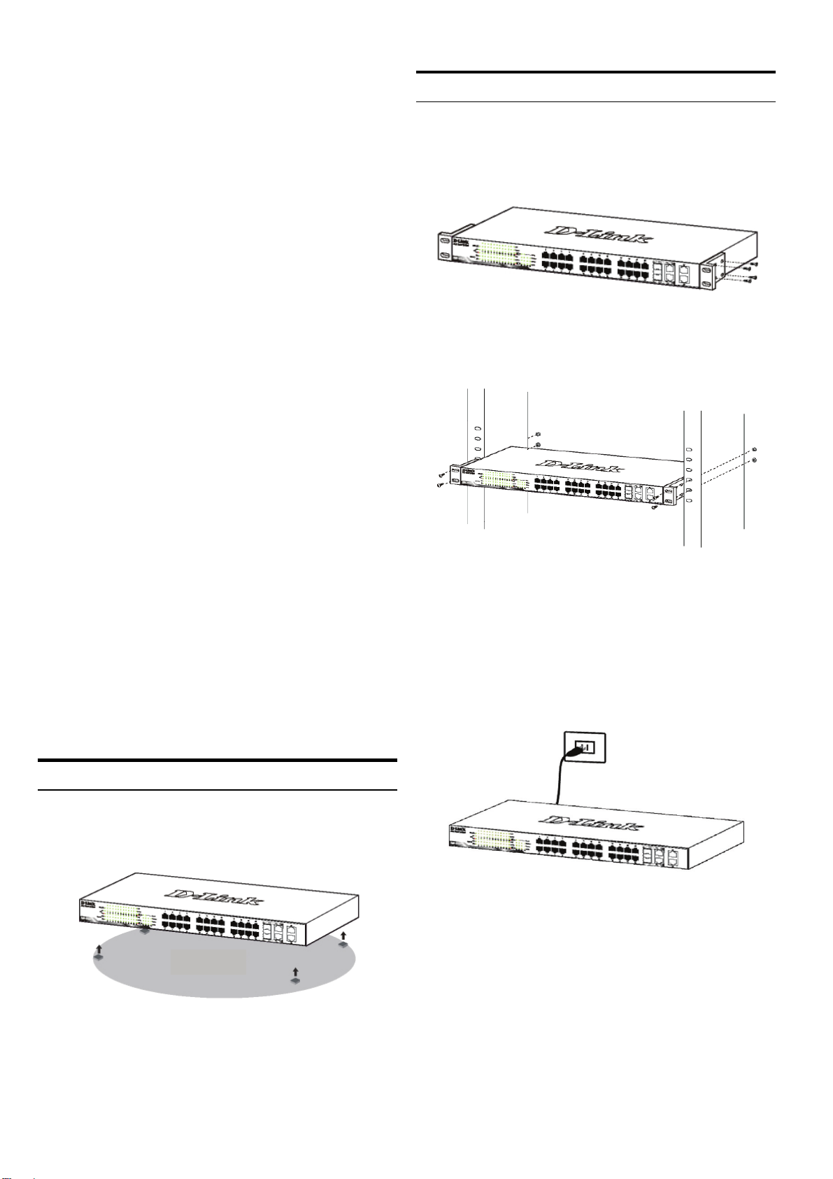
本書の内容
ラックに設置するとき
本書では、D-Link スマートスイッチ全モデル共通の設置・設
定手順を説明しています。使用しているイラストはお手元の
機種とは異なる場合があります。
お手元のスイッチの詳細や、付属品、ネットワーク設定の方
法、スペックなどについては、スイッチに付属のユーザマニュ
アルをご覧ください。
1―パッケージ内容
梱包を開けて、中身をていねいに取り出します。ユーザマニ
ュアルの付属品一覧を見て、同梱物がすべてそろっているか
確認してください。万一不足している部品や破損している部
品がありましたら、弊社ホームページにてユーザ登録を行い、
サポート窓口までご連絡ください。
- D-Link スマートスイッチ 1台
- ラックマウントキット
- 電源ケーブル
- ユーザマニュアル CD(「SmartConsole ユーティリティ」を収
録)
本製品は EIA 規格の 19 インチラックに取り付けることができ、
サーバルームなどに設置する場合に便利です。はじめに、ラ
ックマウントキットを付属のネジで本製品の両側面に取り付
けます。
図2 ラックマウントキットを取り付ける
次に、付属のネジを使用して、スイッチをラックに固定します。
- スタートガイド(多言語版)
2―設置
安全にお使いいただくために、以下の点に注意してください。
電源ケーブルを本体の電源コネクタに確実に差し込ん
でください。
本製品の周囲には、放熱と通気のために十分なスペ
ースを確保してください。
本製品の上に重たいものを置かないでください。
平置きおよび棚などへの設置
平置きおよび棚などに設置する場合は、付属のゴム足を本体底面
の四隅に取り付けます。周囲には通気のために十分なスペースを
確保し設置してください。
図3 スイッチをラックに取り付ける
3―電源ケーブルの接続
電源ケーブルを本体背面の電源コネクタに接続し、もう一方
をコンセントに差し込みます。(コンセントはアース付きでサー
ジ対策のあるものをおすすめします。)
図4 電源ケーブルの接続
停電の際には
ゴム足
図1 ゴム足を取り付ける
停電の際には念のためコンセントを抜きます。電力が復旧し
てから、再度コンセントをつないでください。
38

管理方法
D-Link Web スマートスイッチは Telnet を使ったインバン
ドでの設定管理が可能です。また、ブラウザや
「SmartConsole Utility」を使った Web ベースでも管理を行
うことができます。
管理する D-Link スマートスイッチが1台の場合は、Web
ベース管理ユーティリティをおすすめします。Web ベー
ス管理ユーティリティまたはその他の SNMP ネットワー
ク管理ツールと本製品の通信用に、本製品に固有の IPア
ドレスを割り当てます。また、設定用コンピュータの IP
アドレスは、本製品と同じ IP ネットワークに設定する必
要があります。
複数の D-Link スマートスイッチを管理したい場合は、
SmartConsole ユーティリティの使用をおすすめします。
SmartConsole ユーティリティを使えば、コンピュータの
IP アドレスを変更する必要はありません。複数のスマー
トスイッチの初期設定も簡単に行えます。
ユーティリティのインストールの詳細については、以下
をご覧ください。Telnet 管理と SNMP 管理。
Web ベース管理インターフェイス
Webブラウザを使って、スイッチの設定、ステータスLEDのモ
ニタリング、統計情報のグラフ表示などができます。使用可
能なブラウザは、Netscape Navigator(バージョン6.2以降)や
Microsoft
ウェブブラウザを使ったスイッチの設定には、以下のものが
必要です。
イーサネットポート(RJ-45)を持つコンピュータ
標準的なイーサネットケーブル
®
Internet Explorer(バージョン5.0以降)などです。
ステップ2
イーサネット接続経由でスイッチへのログインや設定を
行なうには、PC はスイッチと同じ範囲内の IP アドレス
を所有している必要があります。スイッチが 10.90.90.90
の IP アドレスを所有している場合、PC は 10.x.y.z(x 及
び y は 0~254、z は 1~254 の値)でサブネットマスクは
255.0.0.0 である必要があります。
Web ブラウザを起動し、アドレス欄に「http://10.90.90.90」(初
期設定の IP アドレス)と入力し、Enter キーを押します。
図7 Web ブラウザ上で IP アドレス「10.90.90.90」を入力
SmartConsole ユーティリティを使って Web 設定画面を開くこ
ともできます。SmartConsole ユーティリティを開いて、
「Device List」からスイッチ名をダブルクリックすると、ブラウ
ザ上にウェブ設定画面が表示されます。
初期設定値は以下の通りです。
IP アドレス:10.90.90.90
サブネットマスク:255.0.0.0
ゲートウェイ:0.0.0.0
ステップ3
以下のようなログインダイアログが表示されたら、
「Password」に「admin」と入力します。「OK」ボタン
をクリックするとメイン設定画面が表示されます。
ステップ1
イーサネットケーブルを使って、スイッチ前面のいずれかのポ
ートとコンピュータのイーサネットポートを接続します。
図6 イーサネットケーブルの接続
図8 ログインダイアログ
ステップ4
Web ベースでの管理の前に Smart Wizard でパスワードや
SNMP、システムなどの設定ができます。初期設定を変更し
ない場合、Exit をクリックして Smart Wizard を終了し、Web ベ
ース管理を開始してください。Smart Wizard での機能設定の
詳細については、ユーザマニュアルを参照してください。
39

SmartConsole ユーティリティ
インストール CD に収録されている「SmartConsole ユー
ティリティ」は、設定用コンピュータが接続されている
レイヤ2ネットワークセグメント内のスマートスイッチ
を検出します。このユーティリティが動作する OS は、
Windows 2000、Windows XP、Windows Vista x64/86 です。
SmartConsole ユーティリティのインストール方法には、
インストール CD のオートランを利用する方法と、手動
インストールの二通りがあります。
注意:古いバージョンの SmartConsole ユーティリティ
がインストールされている場合は、必ず古いバージョン
をアンインストールしてから最新版をインストールして
ください。
1:インストール CD のオートランを利用したインスト
ール
1. インストール CD をコンピュータの CD-ROM ドライ
ブにセットする
2. オートランが自動的にスタートします。
3. 「Install SmartConsole Utility」ボタンをクリックする
インストールウィザードの指示に従ってインストー
ルしてください。
4. インストールが完了したら、「スタート」メニュー
の 「すべてのプログラム」から「 D-Link
SmartConsole Utility」をクリックし、SmartConsole
ユーティリティを起動します。
5. スマートスイッチを設定用コンピュータと同じレイ
ヤ2ネットワークセグメントに接続し、
SmartConsole ユーティリティを使ってスマートスイ
ッチを検出してください。
2:手動インストール
1. インストール CD をコンピュータの CD-ROM ドラ
イブにセットする
2. Windows の「スタート」メニューから、「ファイル
名を指定して実行」
3. 「名前」に「D:\D-Link SmartConsole
Utility\setup.exe(「D:」の部分はご使用の CD-ROM
ドライブ名を指定してください)」と入力し、
「OK」をクリックする
4. 画面の指示に従ってユーティリティをインストー
ルしてください。
5. インストールが完了したら、「スタート」メニュ
ーの「すべてのプログラム」から「D-Link
SmartConsole Utility」をクリックして SmartConsole
ユーティリティを起動します。
6. スマートスイッチを設定用コンピュータと同じレ
イヤ2ネットワークセグメントに接続し、
を選択する
SmartConsole ユーティリティを使ってスマートス
イッチを検出してください。
SmartConsole ユーティリティの詳細については、ユーザ
マニュアルの SmartConsole ユーティリティのページを
ご覧ください。
Telnet 管理
コンピュータのコマンドプロンプトを使用して、Telnet 経由でス
イッチにアクセスすることができます。コンピュータからのアク
セスにはイーサネット経由でのスイッチとの接続が必要です。
「スタート > プログラム > アクセサリ」から「コマンドプロンプ
ト」をクリックしてください。コンソール画面から telnet
10.90.90.90(IP アドレス)を入力、Enter を押します。コマンドラ
インインターフェイス(CLI)のコンソール画面が直接開かれま
す。ユーザ名(admin)とパスワードを入力して Enter を押しま
す。
SNMP 管理
「D-View」やSNMP対応プログラムでも管理することができま
す。SNMP機能の初期値はDisabled(無効)です。
製品に関するお問い合わせについて
ネットワークの設定について不明な点がある場合は、本製品
に付属のユーザマニュアルをご覧ください。ネットワークを稼
動させるためのアドバイス、図解、説明、事例などがより詳し
く記載されています。
さらにサポートが必要な場合は、下記事項をご確認のうえ、
事前にユーザ登録を行い弊社サポート窓口へお問い合わせ
ください。
1.ユーザマニュアルを再度ご確認ください。
2.弊社ホームページにてサポート情報をご確認ください。
3.ダウンロードサービスをご利用ください。
・ダウンロードサービスをご利用になるためには必ずユーザ登録が必要です
・最新情報は弊社ホームページにてご確認ください。
http://www.dlink-jp.com/
40

41

42

43

44

45

46

47

Ver. 2.01(ww)
2009/09/08
290726001210281
48
 Loading...