

Page 1

CLI Reference Guide
Product Model: DES-1210-52/ME
L2 Managed Metro Ethernet Switch
Version 1.00 (release 20.01)
Page 2

Page 3

Information in this document is subject to change without notice.
© 2009 D-Link Computer Corporation. All rights reserved.
Reproduction in any manner whatsoever without the written permission of D-Link Computer Corporation
is strictly forbidden.
Trademarks used in this text: D-Link and the D-Link logo are trademarks of D-Link Computer
Corporation; Microsoft and Windows are registered trademarks of Microsoft Corporation.
Other trademarks and trade names may be used in th
is document to refer to either the entities claiming the marks and names or their products. D-Link
Computer Corporation disclaims any proprietary interest in trademarks and trade names other than its
own.
FCC Warning
This equipment has been tested and found to comply with the limits for a Class A digital device,
pursuant to Part 15 of the FCC Rules. These limits are designed to provide reasonable protection against
harmful interference when the equipment is operated in a commercial environment. This equipment
generates, uses, and can radiate radio frequency energy and, if not installed and used in accordance
with this user’s guide, may cause harmful interference to radio communications. Operation of this
equipment in a residential area is likely to cause harmful interference in which case the user will be
required to correct the interference at hisown expense.
CE Mark Warning
This is a Class A product. In a domestic environment, this product may cause radio interference in
which case the user may be required to take adequate measures.
Warnung!
Dies ist ein Produkt der Klasse A. Im Wohnbereich kann dieses Produkt Funkstoerungen verursachen. In
diesem Fall kann vom Benutzer verlangt werden, angemessene Massnahmen zu ergreifen.
Precaución!
Este es un producto de Clase A. En un entorno doméstico, puede causar interferencias de radio, en
cuyo case, puede requerirse al usuario para que adopte las medidas adecuadas.
Attention!
Ceci est un produit de classe A. Dans un environnement domestique, ce produit pourrait causer des
interférences radio, auquel cas l`utilisateur devrait prendre les mesures adéquates.
Attenzione!
Il presente prodotto appartiene alla classe A. Se utilizzato in ambiente domestico il prodotto può causare
interferenze radio, nel cui caso è possibile che l`utente debba assumere provvedimenti adeguati.
VCCI Warning
Sept, 2014
Page 4

Table of Contents
INTRODUCTION ...................................................................................................................................................... 1
USING THE CONSOLE CLI ..................................................................................................................................... 3
COMMAND SYNTAX ............................................................................................................................................... 6
BASIC SWITCH COMMANDS ................................................................................................................................. 8
enable password encryption .................................................................................................................................................. 9
disable password encryption ................................................................................................................................................. 9
create account .......................................................................................................................................................................10
config account ......................................................................................................................................................................11
show account ........................................................................................................................................................................11
delete account .......................................................................................................................................................................12
reset account .........................................................................................................................................................................12
show session .........................................................................................................................................................................13
show switch ..........................................................................................................................................................................13
enable jumbo_frame .............................................................................................................................................................14
disable jumbo_frame ............................................................................................................................................................14
show jumbo_frame ...............................................................................................................................................................15
config bootrom password .....................................................................................................................................................15
enable clipaging ...................................................................................................................................................................16
disable clipaging ..................................................................................................................................................................16
enable web ...........................................................................................................................................................................16
disable web ...........................................................................................................................................................................17
enable autoconfig ................................ ................................................................ ................................ .................................17
disable autoconfig ................................................................................................................................................................18
config autoconfig .................................................................................................................................................................18
show autoconfig ...................................................................................................................................................................19
enable auto learning .............................................................................................................................................................19
disable auto learning ............................................................................................................................................................19
save ......................................................................................................................................................................................20
reload config ........................................................................................................................................................................20
reboot ...................................................................................................................................................................................21
reset ......................................................................................................................................................................................24
logout ...................................................................................................................................................................................25
ping ......................................................................................................................................................................................25
ping6 ....................................................................................................................................................................................26
traceroute ................................................................................................ ................................................................ ..............27
traceroute6 ............................................................................................................................................................................27
show cpu port .......................................................................................................................................................................28
reset cpu port ........................................................................................................................................................................29
enable telnet .........................................................................................................................................................................29
disable telnet ........................................................................................................................................................................30
telnet .....................................................................................................................................................................................30
config time_range ................................................................................................................................................................30
show time_range ..................................................................................................................................................................31
show tech support .................................................................................................................................................................32
clear tech support .................................................................................................................................................................33
Page 5

DHCP AUTOIMAGE COMMANDS ........................................................................................................................ 34
enable autoimage ..................................................................................................................................................................34
disable autoimage .................................................................................................................................................................34
show autoimage....................................................................................................................................................................35
SMTP SERVER COMMANDS ............................................................................................................................... 36
enable smtp ..........................................................................................................................................................................36
disable smtp .........................................................................................................................................................................36
config smtp ...........................................................................................................................................................................37
show smtp ............................................................................................................................................................................37
smtp sent_testmsg ................................................................................................................................................................38
MODIFY BANNER AND PROMPT COMMANDS ................................................................................................. 40
config command_prompt .....................................................................................................................................................40
config greeting_message ......................................................................................................................................................41
show greeting_message ........................................................................................................................................................42
SWITCH PORT COMMANDS ................................................................................................................................ 43
config ports ..........................................................................................................................................................................43
config ports ..........................................................................................................................................................................44
show ports ............................................................................................................................................................................45
delete ports ...........................................................................................................................................................................45
LOOPBACK DETECTION COMMANDS ............................................................................................................... 47
enable loopdetect ..................................................................................................................................................................47
disable loopdetect .................................................................................................................................................................47
config loopdetect mode ........................................................................................................................................................48
config loopdetect ports .........................................................................................................................................................48
config loopdetect ..................................................................................................................................................................49
show loopdetect....................................................................................................................................................................49
DOS PREVENTION COMMANDS ......................................................................................................................... 51
config dos_prevention dos_type ..........................................................................................................................................51
show dos_prevention ............................................................................................................................................................52
enable dos_prevention trap_log ...........................................................................................................................................53
disable dos_prevention trap_log...........................................................................................................................................53
PPPOE CIRCUIT ID INSERTION COMMANDS .................................................................................................... 54
config pppoe circuit_id_insertion state ................................................................................................................................54
config pppoe circuit_id_insertion ports ................................................................................................................................55
show pppoe circuit_id_insertion ..........................................................................................................................................55
show pppoe circuit_id_insertion ports .................................................................................................................................56
DHCP SERVER SCREENING COMMANDS ......................................................................................................... 57
config filter dhcp_server ......................................................................................................................................................57
config filter dhcp_server ......................................................................................................................................................58
config filter dhcp_server log state ........................................................................................................................................59
show filter dhcp_server ........................................................................................................................................................59
show dhcp_server screening ................................................................................................................................................59
create filter dhcpv6_server permit_entry .............................................................................................................................60
delete filter dhcpv6_server permit_entry .............................................................................................................................61
config filter dhcpv6_server ports .........................................................................................................................................61
config filter dhcpv6_server log state ....................................................................................................................................62
show filter dhcpv6_server ....................................................................................................................................................62
Page 6

IP-MAC-PORT BINDING COMMANDS ................................................................................................................. 63
create address_binding ip_mac ............................................................................................................................................64
config address_binding ip_mac ports ...................................................................................................................................65
config address_binding ip_mac log ......................................................................................................................................65
show address_binding ip_mac log .......................................................................................................................................66
config address_binding auto_scan .......................................................................................................................................66
config address_binding auto_scan ipv6address ...................................................................................................................66
delete address_binding .........................................................................................................................................................67
show address_binding ..........................................................................................................................................................68
show address_binding auto_scan list ...................................................................................................................................69
enable address_binding dhcp_snoop ....................................................................................................................................69
disable address_binding dhcp_snoop ...................................................................................................................................69
config address_binding dhcp_snoop max_entry ports .........................................................................................................70
show address_binding dhcp_snoop ......................................................................................................................................70
enable address_binding dhcp_pd_snoop ................................................................ ................................ ..............................71
disable address_binding dhcp_pd_snoop .............................................................................................................................71
show address_binding dhcp_pd_snoop ................................................................................................................................72
enable address_binding roaming ..........................................................................................................................................72
disable address_binding roaming .........................................................................................................................................73
show address_binding roaming ............................................................................................................................................73
clear address_binding dhcp_snoop binding_entry ports ......................................................................................................73
NETWORK MANAGEMENT (SNMP) COMMANDS ............................................................................................. 75
create snmp user ...................................................................................................................................................................78
delete snmp user ...................................................................................................................................................................79
show snmp user ....................................................................................................................................................................79
create snmp view ..................................................................................................................................................................80
delete snmp view ..................................................................................................................................................................80
show snmp view ...................................................................................................................................................................81
create snmp community .......................................................................................................................................................81
delete snmp community .......................................................................................................................................................82
show snmp community ........................................................................................................................................................82
config snmp engineID ..........................................................................................................................................................83
show snmp engineID ............................................................................................................................................................83
create snmp group ................................................................................................................................................................84
delete snmp group ................................................................................................................................................................85
show snmp global state ........................................................................................................................................................86
show snmp groups ................................................................................................................................................................86
create snmp host ...................................................................................................................................................................87
delete snmp host ...................................................................................................................................................................88
show snmp host ....................................................................................................................................................................88
create snmp v6host ...............................................................................................................................................................89
delete snmp v6host ...............................................................................................................................................................90
show snmp v6host ................................................................................................................................................................90
enable trusted_host ...............................................................................................................................................................91
disable trusted_host ................................................................................................................................ ..............................91
create trusted_host ................................................................................................................................................................92
show trusted_host .................................................................................................................................................................93
Page 7

delete trusted_host ................................................................................................................................................................93
enable snmp traps .................................................................................................................................................................94
disable snmp traps ................................................................................................................................................................94
enable snmp authenticate_traps ............................................................................................................................................95
disable snmp authenticate_traps ................................................................ ................................................................ ...........95
show snmp traps ...................................................................................................................................................................95
enable snmp linkchange_traps .............................................................................................................................................96
disable snmp linkchange_traps.............................................................................................................................................96
config snmp linkchange_traps ports ....................................................................................................................................97
show snmp traps linkchange_traps .......................................................................................................................................97
config snmp system_contact ................................................................................................................................................98
config snmp system_location ...............................................................................................................................................98
config snmp system_name ...................................................................................................................................................99
config snmp warmstart_traps ...............................................................................................................................................99
config snmp coldstart_traps ...............................................................................................................................................100
enable snmp .......................................................................................................................................................................100
disable snmp .......................................................................................................................................................................100
enable snmp DHCP_ screening traps .................................................................................................................................101
disable snmp DHCP_ screening traps ................................................................................................................................101
enable snmp DHCPv6_ screening traps .............................................................................................................................101
disable snmp DHCPv6_ screening traps ............................................................................................................................102
enable snmp IMPB_violation traps ................................................................................................................................ ....102
disable snmp IMPB_violation traps ...................................................................................................................................103
enable snmp firmware_upgrade_state traps .......................................................................................................................103
disable snmp firmware_upgrade_state traps ......................................................................................................................103
enable snmp LBD traps ......................................................................................................................................................104
disable snmp LBD traps .....................................................................................................................................................104
enable snmp port_security_violation traps .........................................................................................................................105
disable snmp port_security_violation traps ........................................................................................................................105
enable snmp rstpport_state_change traps ...........................................................................................................................105
disable snmp rstpport_state_change traps ..........................................................................................................................106
enable snmp duplicate_IP_detected traps...........................................................................................................................106
disable snmp duplicate_IP_detected traps ................................................................ ................................ ..........................107
DOWNLOAD/UPLOAD COMMANDS ................................................................................................................. 108
download ............................................................................................................................................................................108
upload .................................................................................................................................................................................109
config configuration config_id ...........................................................................................................................................110
show firmware information ................................................................................................................................................110
show config ........................................................................................................................................................................111
show boot_file ....................................................................................................................................................................112
config firmware image_id ..................................................................................................................................................112
DHCP RELAY COMMANDS ................................................................................................................................ 114
enable dhcp_relay ..............................................................................................................................................................115
disable dhcp_relay ..............................................................................................................................................................115
config dhcp_relay port .......................................................................................................................................................116
config dhcp_relay add ipif System .....................................................................................................................................116
config dhcp_relay delete ipif System .................................................................................................................................117
config dhcp_relay hops .....................................................................................................................................................117
Page 8

config dhcp_relay vlan ......................................................................................................................................................117
config dhcp_relay option_82 ..............................................................................................................................................118
config dhcp_relay port_option_82 .....................................................................................................................................119
show dhcp_relay port_option_82 .......................................................................................................................................120
show dhcp_relay ................................................................................................................................................................120
enable dhcp_local_relay .....................................................................................................................................................121
disable dhcp_local_relay ....................................................................................................................................................121
config dhcp_local_relay port ..............................................................................................................................................122
config dhcp_local_relay vlan .............................................................................................................................................122
show dhcp_local_relay .......................................................................................................................................................123
enable dhcpv6_relay ..........................................................................................................................................................123
disable dhcpv6_relay ..........................................................................................................................................................124
show dhcpv6_relay ............................................................................................................................................................124
config dhcpv6_relay ...........................................................................................................................................................125
config dhcpv6_relay hop_count .........................................................................................................................................125
config dhcpv6_relay option_18 ..........................................................................................................................................126
config dhcpv6_relay option_37 ..........................................................................................................................................127
config dhcpv6_relay option_38 ..........................................................................................................................................127
show dhcpv6_relay option_38 ...........................................................................................................................................128
CPU PROTECTION COMMANDS ....................................................................................................................... 129
enable cpu_protect .............................................................................................................................................................129
disable cpu_protect ............................................................................................................................................................129
config cpu_protect type ......................................................................................................................................................130
show cpu_protect ...............................................................................................................................................................130
GRATUITOUS ARP COMMANDS ....................................................................................................................... 132
config gratuitous_arp send ipif_status_up ................................................................................................ ..........................132
config gratuitous_arp send dup_ip_detected ......................................................................................................................133
config gratuitous_arp learning ...........................................................................................................................................133
enable gratuitous_arp log ...................................................................................................................................................134
disable gratuitous_arp log ..................................................................................................................................................134
show gratuitous_arp ...........................................................................................................................................................135
config gratuitous_arp send periodically .............................................................................................................................135
POWER SAVING COMMANDS ........................................................................................................................... 137
config power_saving mode ................................................................................................................................................137
config power_saving ..........................................................................................................................................................137
show power_saving ................................................................................................................................ ............................138
NETWORK MONITORING COMMANDS ............................................................................................................ 139
show packet ports ...............................................................................................................................................................139
show error ports .................................................................................................................................................................140
show utilization ..................................................................................................................................................................141
clear counters .....................................................................................................................................................................142
save log ..............................................................................................................................................................................142
clear log ..............................................................................................................................................................................142
show log .............................................................................................................................................................................143
enable syslog ......................................................................................................................................................................143
disable syslog .....................................................................................................................................................................144
show syslog ........................................................................................................................................................................144
Page 9

create syslog host ...............................................................................................................................................................145
config syslog host...............................................................................................................................................................147
delete syslog host ...............................................................................................................................................................149
show syslog host ................................................................................................................................................................149
cable diagnostic port ..........................................................................................................................................................150
config syslogintimeout .......................................................................................................................................................150
SPANNING TREE COMMANDS.......................................................................................................................... 153
config stp ............................................................................................................................................................................153
config stp ports ...................................................................................................................................................................154
config stp version ...............................................................................................................................................................156
config stp fbpdu .................................................................................................................................................................156
config stp priority ...............................................................................................................................................................157
enable stp ...........................................................................................................................................................................157
disable stp ................................................................................................ ................................................................ ...........157
show stp .............................................................................................................................................................................158
show stp ports ....................................................................................................................................................................159
show stp instance ...............................................................................................................................................................159
show stp mst_config_id......................................................................................................................................................160
create stp instance_id .........................................................................................................................................................160
delete stp instance_id .........................................................................................................................................................161
config stp instance_id .........................................................................................................................................................161
config stp mst_config_id ....................................................................................................................................................162
config stp mst_ports ...........................................................................................................................................................163
config stp trap.....................................................................................................................................................................164
FORWARDING DATABASE COMMANDS ......................................................................................................... 165
create fdb ............................................................................................................................................................................165
create multicast_fdb ...........................................................................................................................................................166
config multicast_fdb ..........................................................................................................................................................166
config fdb aging_time ........................................................................................................................................................167
delete fdb ............................................................................................................................................................................167
enable flood_fdb ................................................................................................................................................................168
disable flood_fdb................................................................................................................................................................168
config flood_fdb .................................................................................................................................................................169
show flood_fdb ..................................................................................................................................................................169
clear flood_fdb ...................................................................................................................................................................169
show flow_meter ................................................................................................................................................................170
show multicast_fdb ............................................................................................................................................................170
show fdb .............................................................................................................................................................................171
config multicast filter .........................................................................................................................................................172
show multicast filter port_mode .........................................................................................................................................172
create auto_fdb ...................................................................................................................................................................173
delete auto_fdb ...................................................................................................................................................................173
show auto_fdb ....................................................................................................................................................................174
BROADCAST STORM CONTROL COMMANDS ............................................................................................... 175
config traffic control ..........................................................................................................................................................175
config traffic control auto_recover_time ............................................................................................................................176
show traffic control ............................................................................................................................................................176
Page 10

config traffic trap ...............................................................................................................................................................177
PASSWORD RECOVERY COMMANDS ............................................................................................................. 178
enable password_recovery .................................................................................................................................................178
disable password_recovery ................................................................................................................................................178
show password_recovery ...................................................................................................................................................179
QOS COMMANDS ............................................................................................................................................... 180
config scheduling ................................ ................................................................................................ ...............................181
show scheduling .................................................................................................................................................................182
config bandwidth_control ..................................................................................................................................................183
show bandwidth_control ....................................................................................................................................................184
config cos mac_mapping....................................................................................................................................................184
show cos mac_mapping .....................................................................................................................................................185
delete cos mac_mapping ....................................................................................................................................................185
config cos ip_mapping ................................................................................................................................ .......................186
show cos ip_mapping .........................................................................................................................................................186
delete cos ip_mapping ........................................................................................................................................................187
config cos ipv6_mapping ...................................................................................................................................................187
show cos ipv6_mapping .....................................................................................................................................................187
delete cos ipv6_mapping ....................................................................................................................................................188
config cos ipv6_tc_mapping ..............................................................................................................................................188
delete cos ipv6_tc_mapping ...............................................................................................................................................189
show cos ipv6_tc_mapping ................................................................................................................................................189
config cos mapping ............................................................................................................................................................190
show cos mapping ..............................................................................................................................................................190
config cos protocol_mapping .............................................................................................................................................191
show cos protocol_mapping ...............................................................................................................................................191
delete cos protocol_mapping ..............................................................................................................................................192
config cos vlanid_mapping ................................................................................................................................................192
show cos vlanid_mapping ..................................................................................................................................................193
delete cos vlanid_mapping .................................................................................................................................................193
config cos tos value ................................................................................................................................ ............................193
show cos tos .......................................................................................................................................................................194
config cos tcp_port_mapping .............................................................................................................................................195
show cos tcp_port_mapping ...............................................................................................................................................195
delete cos tcp_port_mapping ..............................................................................................................................................195
config cos udp_port_mapping ............................................................................................................................................196
show cos udp _port_mapping .............................................................................................................................................196
delete cos udp_port_mapping ............................................................................................................................................197
config 802.1p user_priority ................................................................................................................................................197
show 802.1p user_priority ..................................................................................................................................................198
config 802.1p default_priority ...........................................................................................................................................199
show 802.1p default_priority .............................................................................................................................................199
config scheduling_mechanism ...........................................................................................................................................200
show scheduling_mechanism .............................................................................................................................................200
config dscp mode ...............................................................................................................................................................201
config dscp_mapping .........................................................................................................................................................201
show dscp_mapping ...........................................................................................................................................................202
RMON COMMANDS ............................................................................................................................................ 203
Page 11

enable rmon ........................................................................................................................................................................203
disable rmon .......................................................................................................................................................................204
create rmon alarm ...............................................................................................................................................................204
delete rmon alarm ...............................................................................................................................................................205
create rmon collection stats ................................................................................................................................................205
delete rmon collection stats ................................................................................................................................................206
create rmon collection history ............................................................................................................................................206
delete rmon collection history ............................................................................................................................................207
create rmon event ...............................................................................................................................................................207
delete rmon event ...............................................................................................................................................................208
show rmon ..........................................................................................................................................................................208
show rmon statistics ...........................................................................................................................................................209
PORT MIRRORING COMMANDS ....................................................................................................................... 210
enable mirror ......................................................................................................................................................................210
disable mirror .....................................................................................................................................................................210
config mirror target ............................................................................................................................................................211
show mirror ........................................................................................................................................................................212
VLAN COMMANDS ............................................................................................................................................. 213
create vlan ................................................................................................................................................................ ..........214
delete vlan ..........................................................................................................................................................................214
config vlan .........................................................................................................................................................................215
config gvrp .........................................................................................................................................................................215
config gvrp timer ................................................................................................................................................................216
enable gvrp .........................................................................................................................................................................217
disable gvrp ........................................................................................................................................................................217
show vlan ...........................................................................................................................................................................217
create dot1v_protocol_group .............................................................................................................................................218
config dot1v_protocol_group .............................................................................................................................................219
delete dot1v_protocol_group .............................................................................................................................................219
show dot1v_protocol_group ...............................................................................................................................................220
config port dot1v ports all ..................................................................................................................................................220
show port dot1v ..................................................................................................................................................................221
show gvrp ...........................................................................................................................................................................222
show gvrp timer .................................................................................................................................................................222
enable vlan_trunk ...............................................................................................................................................................223
disable vlan_trunk ..............................................................................................................................................................223
show vlan_trunk .................................................................................................................................................................223
config vlan_trunk ports ......................................................................................................................................................224
enable asymmetric_vlan .....................................................................................................................................................224
disable asymmetric_vlan ....................................................................................................................................................225
show asymmetric_vlan .......................................................................................................................................................225
enable pvid auto_assign .....................................................................................................................................................226
disalbe pvid auto_assign ....................................................................................................................................................226
show pvid auto_assign .......................................................................................................................................................226
Q-IN-Q COMMANDS ............................................................................................................................................ 228
enable qinq .........................................................................................................................................................................228
disable qinq ................................................................ ................................................................................................ ........229
Page 12

show qinq ...........................................................................................................................................................................229
config qinq ports ................................................................................................................................................................230
config qinq inner_tpid ........................................................................................................................................................230
create vlan_translation .......................................................................................................................................................231
show vlan_translation ........................................................................................................................................................231
delete vlan_translation cvid ................................................................................................................................................232
LINK AGGREGATION COMMANDS .................................................................................................................. 233
create link_aggregation ................................ ................................................................ ................................ ......................233
delete link_aggregation ................................ ................................................................................................ ......................234
config link_aggregation group_id ......................................................................................................................................234
config link_aggregation algorithm ................................................................ ................................................................ .....235
config link_aggregation state .............................................................................................................................................235
show link_aggregation .......................................................................................................................................................236
BASIC IP COMMANDS ........................................................................................................................................ 237
create ipif ...........................................................................................................................................................................237
delete ipif ...........................................................................................................................................................................238
enable ipif ................................................................ ................................................................................................ ...........238
disable ipif ..........................................................................................................................................................................238
config ipif ...........................................................................................................................................................................239
BPDU ATTACK PROTECTION COMMANDS .................................................................................................... 241
config bpdu_protection ports .............................................................................................................................................241
config bpdu_protection recovery_timer .............................................................................................................................242
config bpdu_protection ......................................................................................................................................................243
enable bpdu_protection ................................ ................................................................................................ ......................243
disable bpdu_protection .....................................................................................................................................................244
show bpdu_protection ........................................................................................................................................................244
ETHERNET OAM COMMANDS .......................................................................................................................... 246
config ethernet_oam ports ................................ ................................................................................................ ..................246
config ethernet_oam ports ................................ ................................................................................................ ..................247
config ethernet_oam ports ................................ ................................................................................................ ..................247
show ethernet_oam ports....................................................................................................................................................248
show ethernet_oam ports....................................................................................................................................................249
show ethernet_oam ports....................................................................................................................................................250
show ethernet_oam ports....................................................................................................................................................251
clear ethernet_oam ports ....................................................................................................................................................252
MAC NOTIFICATION COMMANDS .................................................................................................................... 253
enable mac_notification .....................................................................................................................................................253
disable mac_notification ....................................................................................................................................................253
config mac_notification .....................................................................................................................................................254
config mac_notification ports ............................................................................................................................................254
show mac_notification .......................................................................................................................................................255
show mac_notification ports ..............................................................................................................................................255
IGMP SNOOPING COMMANDS.......................................................................................................................... 257
config igmp_snooping ........................................................................................................................................................258
config igmp_snooping querier ...........................................................................................................................................259
create igmp_snooping multicast_vlan ................................................................................................................................260
config igmp_snooping multicast_vlan ................................................................ ................................ ...............................260
Page 13

delete igmp_snooping multicast_vlan ................................................................................................................................261
config igmp_snooping multicast_vlan_group ....................................................................................................................261
create igmp_snooping static_group ....................................................................................................................................262
config igmp_snooping static_group ...................................................................................................................................262
delete igmp_snooping static_group ....................................................................................................................................263
show igmp_snooping static_group .....................................................................................................................................263
config igmp_snooping data_driven_learning .....................................................................................................................264
config igmp_snooping data_driven_learning .....................................................................................................................265
clear igmp_snooping data_driven_group ...........................................................................................................................265
config router_ports .............................................................................................................................................................266
config router_ports_forbidden ...........................................................................................................................................266
config igmp access_authentication ports ............................................................................................................................267
show igmp access_authentication ports .............................................................................................................................267
enable igmp_snooping .......................................................................................................................................................268
disable igmp_snooping.......................................................................................................................................................268
show igmp_snooping .........................................................................................................................................................269
show igmp_snooping group ...............................................................................................................................................270
show igmp_snooping forwarding .......................................................................................................................................270
show igmp_snooping host ................................................................................................................................ ..................271
show igmp_snooping multicast_vlan .................................................................................................................................272
show igmp_snooping multicast_vlan_group ......................................................................................................................272
show router_ports ...............................................................................................................................................................273
DIGITAL DIAGNOSTIC MONITORING COMMANDS......................................................................................... 274
config ddm ports ................................................................................................................................................................274
config ddm power_unit ......................................................................................................................................................275
show ddm ports ..................................................................................................................................................................275
MLD SNOOPING COMMANDS ........................................................................................................................... 277
enable mld_snooping .........................................................................................................................................................278
disable mld_snooping ........................................................................................................................................................278
config mld_snooping ..........................................................................................................................................................279
create mld_snooping multicast_vlan ..................................................................................................................................279
config mld_snooping multicast_vlan .................................................................................................................................280
show mld_snooping multicast_vlan ................................................................ ................................ ...................................281
delete mld_snooping multicast_vlan ..................................................................................................................................281
config mld_snooping multicast_vlan_group ......................................................................................................................282
show mld_snooping multicast_vlan_group ........................................................................................................................282
config mld_snooping mrouter_ports ..................................................................................................................................283
config mld_snooping mrouter_port_forbidden ..................................................................................................................283
config mld_snooping querier .............................................................................................................................................284
config mld_snooping data_driven_learning .......................................................................................................................285
clear mld_snooping data_driven_group .............................................................................................................................286
show mld_snooping ...........................................................................................................................................................286
show mld_snooping forwarding ................................................................ ................................................................ .........287
show mld_snooping group .................................................................................................................................................288
show mld_snooping mrouter_ports ....................................................................................................................................288
show mld_snooping host ....................................................................................................................................................289
LIMITED IP MULTICAST ADDRESS COMMANDS ............................................................................................ 290
Page 14

create mcast_filter_profile .................................................................................................................................................290
config mcast_filter_profile profile_id ...............................................................................................................................291
config mcast_filter_profile profile_name ................................................................ ................................ ..........................291
config mcast_filter_profile ipv6 ................................ ................................ ................................................................ ........292
delete mcast_filter_profile .................................................................................................................................................292
show mcast_filter_profile...................................................................................................................................................293
config limited_multicast_addr ...........................................................................................................................................294
show limited_multicast_addr .............................................................................................................................................294
config max_mcast_group ...................................................................................................................................................295
show max_mcast_group .....................................................................................................................................................295
LAYER 2 PROTOCOL TUNNELING COMMANDS ............................................................................................ 297
enable l2protocol_tunnel ....................................................................................................................................................297
disable l2protocol_tunnel ...................................................................................................................................................297
config l2protocol_tunnel ....................................................................................................................................................298
show l2protocol_tunnel ......................................................................................................................................................298
802.1X COMMANDS ............................................................................................................................................ 300
enable 802.1x .....................................................................................................................................................................301
disable 802.1x ....................................................................................................................................................................301
show 802.1x .......................................................................................................................................................................302
show 802.1x auth_state ................................................................................................ ................................ ......................302
show 802.1x auth_configuration ........................................................................................................................................303
config 802.1x auth_parameter ports ...................................................................................................................................304
config 802.1x init ................................................................................................ ................................ ...............................305
config 802.1x auth_protocol ..............................................................................................................................................306
config 802.1x reauth ..........................................................................................................................................................306
config radius add ................................................................................................................................................................307
config radius delete ............................................................................................................................................................308
config radius .......................................................................................................................................................................308
show radius ........................................................................................................................................................................309
config 802.1x fwd_pdu system ..........................................................................................................................................309
show 802.1x fwd_pdu system status ..................................................................................................................................310
config 802.1x auth_mode ................................................................................................................................ ...................310
create 802.1x guest_vlan ....................................................................................................................................................311
delete 802.1x guest_vlan ....................................................................................................................................................311
config 802.1x guest_vlan ports ..........................................................................................................................................312
show 802.1x guest_vlan .....................................................................................................................................................312
create 802.1x user ..............................................................................................................................................................313
show 802.1x user................................................................................................................................................................313
delete 802.1x user ..............................................................................................................................................................314
config 802.1x capability ports ............................................................................................................................................314
PORT SECURITY COMMANDS .......................................................................................................................... 316
config port_security ...........................................................................................................................................................316
show port_security .............................................................................................................................................................317
delete port_security _entry .................................................................................................................................................318
TIME AND SNTP COMMANDS ........................................................................................................................... 319
config sntp ..........................................................................................................................................................................319
show sntp ...........................................................................................................................................................................320
Page 15

enable sntp .........................................................................................................................................................................320
disable sntp .........................................................................................................................................................................321
config time .........................................................................................................................................................................321
config time_zone operator ..................................................................................................................................................322
config dst ............................................................................................................................................................................322
show time ...........................................................................................................................................................................323
ARP COMMANDS ................................................................................................................................................ 325
create ArpSpoofing ............................................................................................................................................................325
show ArpSpoofing .............................................................................................................................................................326
delete ArpSpoofing ............................................................................................................................................................326
config arp_aging time ........................................................................................................................................................327
clear arptable ......................................................................................................................................................................327
create arpentry ....................................................................................................................................................................328
config arpentry ...................................................................................................................................................................328
delete arpentry ....................................................................................................................................................................329
show arpentry ................................................................................................................................................................ .....329
show arpentry aging_time ..................................................................................................................................................330
ROUTING TABLE COMMANDS.......................................................................................................................... 331
create iproute ......................................................................................................................................................................331
delete iproute ......................................................................................................................................................................332
show iproute .......................................................................................................................................................................332
STATIC MAC_BASED VLAN COMMANDS ....................................................................................................... 333
create mac_based_vlan mac_address .................................................................................................................................333
delete mac_based_vlan.......................................................................................................................................................334
show mac_based_vlan ........................................................................................................................................................334
D-LINK UNIDIRECTIONAL LINK DETECTION (DULD) COMMANDS .............................................................. 335
config duld ports ................................................................................................................................................................335
show duld ports ..................................................................................................................................................................336
config duld recover_timer ..................................................................................................................................................336
show duld recover_timer ....................................................................................................................................................337
IPV6 NEIGHBOR DISCOVERY COMMANDS ..................................................................................................... 338
create ipv6 neighbor_cache ................................................................................................................................................338
delete ipv6 neighbor_cache ................................................................................................................................................339
show ipv6 neighbor_cache .................................................................................................................................................339
show ipv6 nd ......................................................................................................................................................................340
config ipv6 nd ns ipif System .............................................................................................................................................340
create ipv6route default ......................................................................................................................................................341
delete ipv6route default ......................................................................................................................................................341
show ipv6route ................................ ................................................................ ................................ ...................................342
enable ipif_ipv6_link_local_auto System ..........................................................................................................................342
disable ipif_ipv6_link_local_auto System .........................................................................................................................343
BANNER COMMANDS ........................................................................................................................................ 344
config log_save_timing ......................................................................................................................................................344
show log_save_timing ........................................................................................................................................................345
show log_software_module ...............................................................................................................................................345
show log .............................................................................................................................................................................346
COMMAND HISTORY LIST COMMANDS .......................................................................................................... 347
Page 16

? ..........................................................................................................................................................................................347
show command_history .....................................................................................................................................................348
dir .......................................................................................................................................................................................349
SSH COMMANDS ................................................................................................................................................ 350
enable ssh ...........................................................................................................................................................................350
disable ssh ..........................................................................................................................................................................351
config ssh algorithm ................................................................................................ ................................ ...........................351
config ssh authmode ...........................................................................................................................................................352
show ssh authmode ............................................................................................................................................................352
config ssh server.................................................................................................................................................................353
show ssh server ..................................................................................................................................................................353
show ssh algorithm .............................................................................................................................................................354
config ssh user ....................................................................................................................................................................355
show ssh user authmode .....................................................................................................................................................355
SSL COMMANDS ................................................................................................................................................ 356
enable ssl ............................................................................................................................................................................356
disable ssl ...........................................................................................................................................................................357
show ssl ................................................................................................................................................................ ..............357
download ssl certificate ......................................................................................................................................................358
ACCESS AUTHENTICATION CONTROL COMMANDS .................................................................................... 359
create authen_login method_list_name ..............................................................................................................................360
config authen_login ............................................................................................................................................................360
delete authen_login method_list_name ..............................................................................................................................362
show authen_login .............................................................................................................................................................362
show authen_policy ............................................................................................................................................................363
create authen_enable method_list_name ............................................................................................................................363
config authen_enable .........................................................................................................................................................364
delete authen_enable method_list_name ............................................................................................................................365
show authen_enable ...........................................................................................................................................................366
enable authen_policy ..........................................................................................................................................................366
disable authen_policy .........................................................................................................................................................367
config authen application ...................................................................................................................................................367
show authen application .....................................................................................................................................................368
config authen parameter .....................................................................................................................................................369
show authen parameter .......................................................................................................................................................369
create authen server_host ...................................................................................................................................................369
config authen server_host ..................................................................................................................................................371
delete authen server_host ...................................................................................................................................................372
show authen server_host ....................................................................................................................................................372
create authen server_group ................................................................................................................................................373
config authen server_group ................................................................................................................................................374
delete authen server_group ................................................................................................................................................374
show authen server_group ..................................................................................................................................................375
enable admin ......................................................................................................................................................................376
config admin local_enable .................................................................................................................................................376
LACP COMMANDS ............................................................................................................................................. 378
config lacp port_priority ....................................................................................................................................................378
Page 17

show lacp ...........................................................................................................................................................................378
config lacp_ports ................................................................................................................................................................379
LLDP COMMANDS .............................................................................................................................................. 381
enable lldp ..........................................................................................................................................................................382
disable lldp .........................................................................................................................................................................382
config lldp message_tx_interval.........................................................................................................................................382
config lldp message_tx_hold_multiplier ................................................................................................ ............................383
config lldp reinit_delay ......................................................................................................................................................383
config lldp tx_delay ...........................................................................................................................................................384
config lldp notification_interval ................................................................ ................................................................ .........384
show lldp ............................................................................................................................................................................384
show lldp ports ...................................................................................................................................................................385
show lldp local_ports .........................................................................................................................................................386
show lldp remote_ports ......................................................................................................................................................386
config lldp ports .................................................................................................................................................................387
show lldp power_pse_tlv....................................................................................................................................................391
show lldp mgt_addr ............................................................................................................................................................392
show lldp statistics .............................................................................................................................................................393
ACCESS CONTROL LIST COMMANDS ............................................................................................................ 394
create access_profile ..........................................................................................................................................................395
config access_profile ..........................................................................................................................................................397
delete access_profile ..........................................................................................................................................................401
show access_profile ...........................................................................................................................................................401
create cpu_access_profile ...................................................................................................................................................402
config cpu_access_profile ..................................................................................................................................................403
delete cpu_access_profile ...................................................................................................................................................405
enable cpu_interface_filtering ............................................................................................................................................406
disable cpu_interface_filtering ...........................................................................................................................................406
show cpu_access_profile ....................................................................................................................................................407
config flow_meter profile_id .............................................................................................................................................407
TRAFFIC SEGMENTATION COMMANDS .......................................................................................................... 409
config traffic_segmentation ...............................................................................................................................................409
show traffic_segmentation .................................................................................................................................................409
SAFEGUARD COMMANDS ................................................................................................................................ 411
config safeguard_engine ....................................................................................................................................................411
show safeguard_engine ................................ ................................................................ ................................ ......................411
DEVICE SPECIFICATIONS ................................................................................................................................. 413
Technical Specifications ....................................................................................................................................................413
Supported Transceivers ......................................................................................................................................................415
Page 18

Page 19
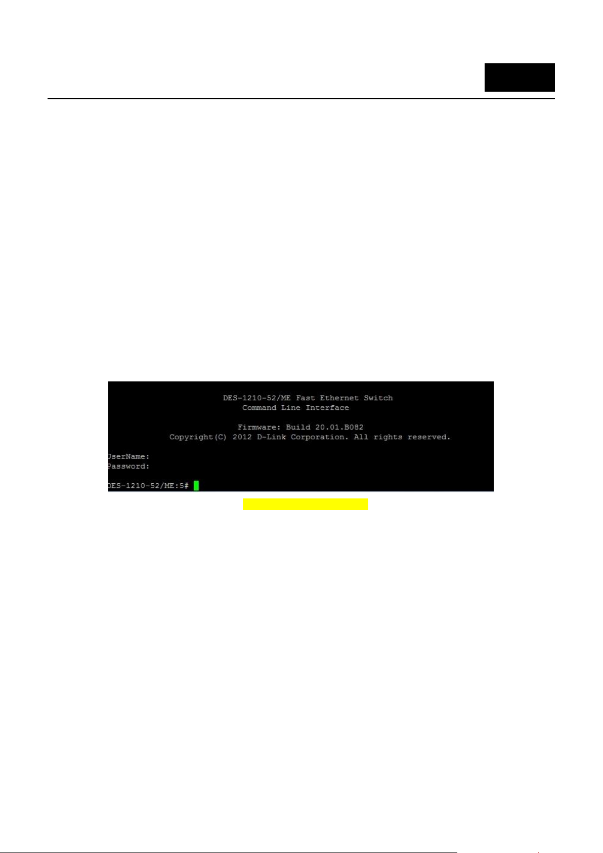
DES-1210-52/ME L2 Metro Ethernet Switch CLI Reference Guide
1
INTRODUCTION
The DES-1210-52/ME is L2 Metro Ethernet switche. It consists of 48 10/100Mbps ports plus 4 combo
10/100/1000Base-T ports and 2 dedicated SFP ports.
The Switch can be managed through the Switch’s serial port, Telnet, or the Web-based management
agent. The Command Line Interface (CLI) can be used to configure and manage the Switch via the serial
port or Telnet interfaces.
This manual provides a reference for all of the commands contained in the CLI. Configuration and
management of the Switch via the Web-based management agent is discussed in the Manual. For
detailed information on installing hardware please refer also to the Manual.
Accessing the Switch via the Serial Port.
The Switch’s serial port’s default settings are as follows:
9600 bps
No parity
8 data bits
1 stop bit
A computer running a terminal emulation program capable of emulating a VT-100 terminal and a serial
port configured as above then connected to the Switch’s serial port via an RJ-45 cable.
With the serial port properly connected to a management computer, the following screen should be
visible. If this screen does not appear, try pressing Ctrl+r to refresh the console screen.
Figure 1–1 Initial CLI screen
There is no initial username or password. Just press the Enter key twice to display the CLI input cursor
− DES-1210-52/ME:5#. This is the command line where all commands are input.
Setting the Switch’s IP Address
Each Switch must be assigned its own IP Address, which is used for communication with an SNMP
network manager or other TCP/IP application (for example BOOTP, TFTP). The Switch’s default IP
address is 10.90.90.90. You can change the default Switch IP address to meet the specification of your
networking address scheme.
The Switch is also assigned a unique MAC address by the factory. This MAC address cannot be changed,
but can be found on the initial boot console screen – shown below.
1
Page 20
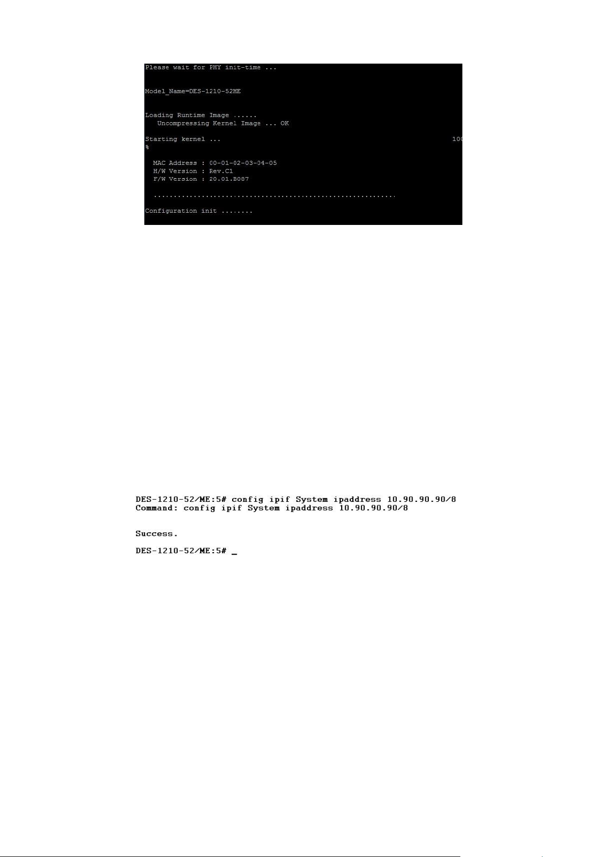
DES-1210-52/ME L2 Metro Ethernet Switch CLI Reference Guide
Figure 1–2 Boot Screen
The Switch’s MAC address can also be found in the Web management program on the Switch
Information (Basic Settings) window in the Configuration folder.
The IP address for the Switch must be set before it can be managed with the Web-based manager. The
Switch IP address can be automatically set using BOOTP or DHCP protocols, in which case the actual
address assigned to the Switch must be known.
The IP address may be set using the Command Line Interface (CLI) over the console serial port as
follows:
Starting at the command line prompt, enter the command config ipif System ipaddress
xxx.xxx.xxx.xxx/yyy.yyy.yyy.yyy. Where the x’s represent the IP address to be assigned to the IP
interface named System and the y’s represent the corresponding subnet mask.
Alternatively, users can enter config ipif System ipaddress xxx.xxx.xxx.xxx/z. Where the x’s represent
the IP address to be assigned to the IP interface named System and the z represents the corresponding
number of subnets in CIDR notation.
The IP interface named System on the Switch can be assigned an IP address and subnet mask which
can then be used to connect a management station to the Switch’s Telnet or Web-based management
agent.
Figure 1–3 Assigning an IP Address
In the above example, the Switch was assigned an IP address of 10.90.90.91 with a subnet mask of
255.0.0.0. The system message Success. indicates that the command was executed Success.fully. The
Switch can now be configured and managed via Telnet, SNMP MIB browser and the CLI or via the Webbased management agent using the above IP address to connect to the Switch.
2
Page 21

DES-1210-52/ME L2 Metro Ethernet Switch CLI Reference Guide
NOTE: Switch configuration settings are saved to non-volatile RAM using the save command.
The current configuration will then be retained in the Switch’s NV-RAM, and reloaded when the
Switch is rebooted. If the Switch is rebooted without using the save command, the last
configuration saved to NV-RAM is loaded.
2
USING THE CONSOLE CLI
The Switch supports a console management interface that allows the user to connect to the Switch’s
management agent via a serial port and a terminal or a computer running a terminal emulation program.
The console can also be used over the network using the TCP/IP Telnet protocol. The console program
can be used to configure the Switch to use a SNMP-based network management software over the
network.
This chapter describes how to use the console interface to access the Switch, change its settings, and
monitor its operation.
Connecting to the Switch
The console interface is used by connecting the Switch to a VT100-compatible terminal or a computer
running an ordinary terminal emulator program (for example, the HyperTerminal program included with
the Windows operating system) using an RJ-45 serial cable. Your terminal parameters will need to be set
to:
VT-100 compatible
9600 bps
8 data bits
No parity
One stop bit
No flow control
The same functions may also be accessed over a Telnet interface. Once an IP address for the Switch has
been set, A Telnet program can be used (in VT-100 compatible terminal mode) to access and control the
Switch. All of the screens are identical, whether accessed from the console port or from a Telnet
interface.
After the Switch reboots and you have to logged in, the console looks like this:
Figure 2–1 Initial Console Screen after Logging In
Commands are entered at the command prompt, DES-1210-52/ME:5#
There are a number of helpful features included in the CLI. Entering the ? command displays a list of all
of the top-level commands.
3
Page 22
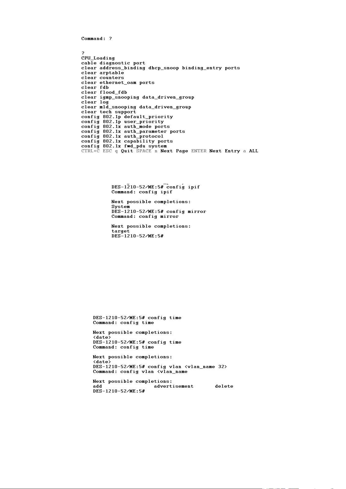
DES-1210-52/ME L2 Metro Ethernet Switch CLI Reference Guide
Figure 2–2 The ? Command
When entering a command without its required parameters, the CLI displays the prompt: command:
config account message and the options listed below.
Figure 2–3 Example Command Parameter Help
In this case, the command config account was entered with the parameter <username>. The CLI will then
prompt to enter the <username> with the message, command: config account. Every command in the
CLI has this feature, and complex commands have several layers of parameter prompting.
In addition, after typing any given command plus one space, users can see all of the next possible subcommands, in sequential order, by pressing the ? key.
To re-enter the previous command at the command prompt, press the up arrow cursor key. The previous
command appears at the command prompt.
Figure 2–4 Using the Up Arrow to Re-enter a Command
In the above example, the command config account was entered without the required parameter
<username>, the CLI returned the command: config account prompt. The up arrow cursor control key
4
Page 23
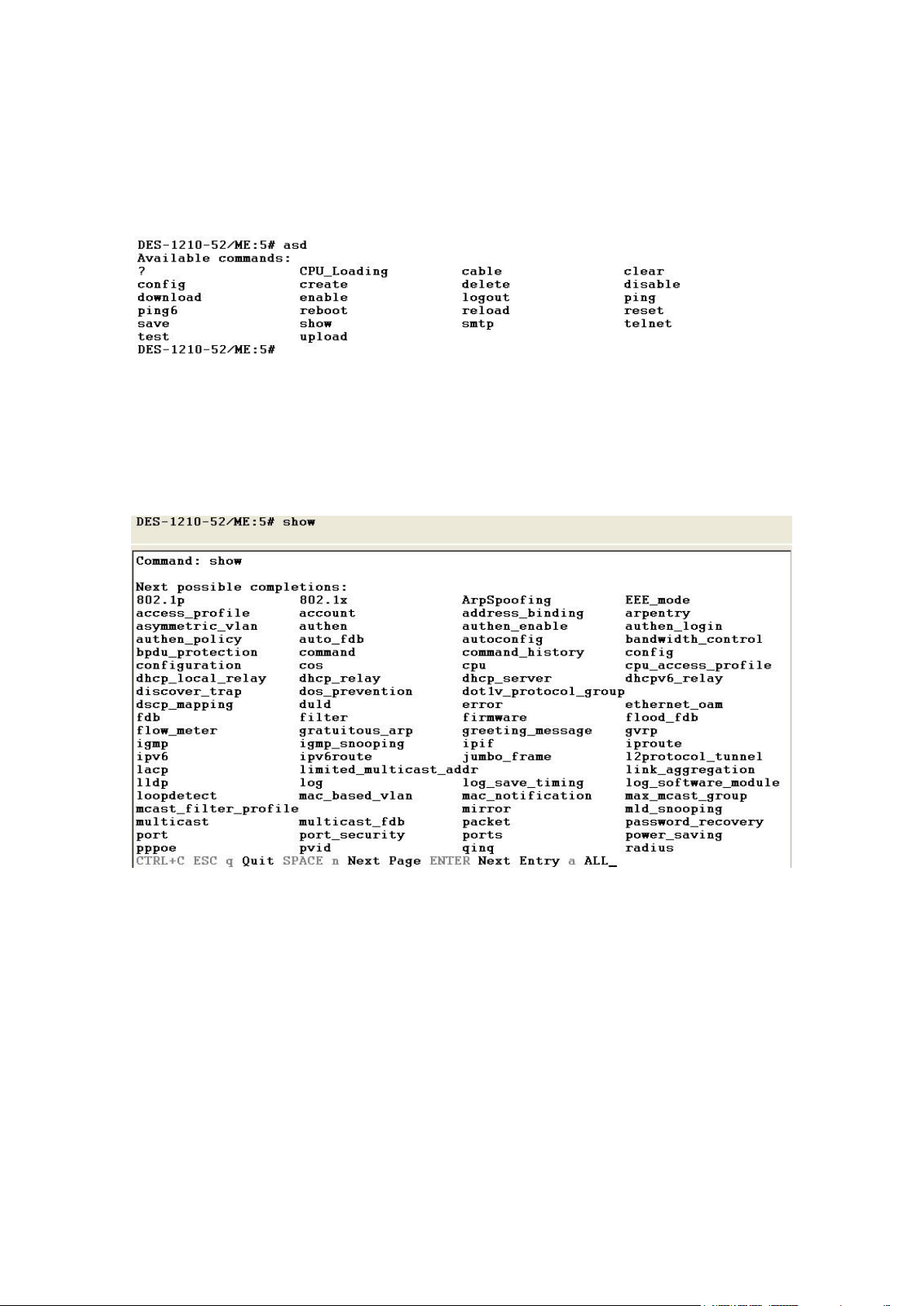
DES-1210-52/ME L2 Metro Ethernet Switch CLI Reference Guide
was pressed to re-enter the previous command (config account) at the command prompt. Now the
appropriate username can be entered and the config account command re-executed.
All commands in the CLI function in this way. In addition, the syntax of the help prompts are the same as
presented in this manual angle brackets < > indicate a numerical value or character string. The < > can
also indicate a word with a number for character allowed.
If a command is entered that is unrecognized by the CLI, the top-level commands are displayed under
the Available commands: prompt.
Figure 2–5 Available Commands
The top-level commands consist of commands such as show or config. Most of these commands
require one or more parameters to narrow the top-level command. This is equivalent to show what? or
config what? Where the what? is the next parameter.
For example, entering the show command with no additional parameters, the CLI will then display all of
the possible next parameters.
Figure 2–6 Next possible completions: Show Command
In the above example, all of the possible next parameters for the show command are displayed. At the
next command prompt in the example, the up arrow was used to re-enter the show command, followed
by the account parameter. The CLI then displays the user accounts configured on the Switch.
5
Page 24

DES-1210-52/ME L2 Metro Ethernet Switch CLI Reference Guide
NOTE: All commands are case-sensitive. Be sure to disable Caps Lock or any other unwanted
function that changes text case.
<angle brackets>
Purpose
Encloses a variable or value that must be specified.
Syntax
create account [admin | operator | power-user |user]
<username 15>
Description
In the above syntax example, supply a username in the <username
15> space. Do not type the angle brackets.
Example
Command
create account admin newadmin1
[square brackets]
Purpose
Encloses a required value or set of required arguments. One value
or argument can be specified.
Syntax
create account [admin | operator | power-user |user]
<username 15>
Description
In the above syntax example, specify admin, oper or a user level
account to be created. Do not type the square brackets.
Example
Command
create account user newuser1
| vertical bar
Purpose
Separates two or more mutually exclusive items in a list, one of
which must be entered.
Syntax
create account [admin | operator | power-user |user]
<username 15>
Description
In the above syntax example, specify admin, oper, or user. Do not
type the vertical bar.
Example
Command
create account user newuser1
3
COMMAND SYNTAX
The following symbols are used to describe how command entries are made and values and arguments
are specified in this manual. The online help contained in the CLI and available through the console
interface uses the same syntax.
All commands are case-sensitive. Be sure to disable Caps Lock or any other unwanted function that
changes text case.
6
Page 25

DES-1210-52/ME L2 Metro Ethernet Switch CLI Reference Guide
{braces}
Purpose
Encloses an optional value or set of optional arguments.
Syntax
reset
Description
execute “reset” will return the switch to its factory default setting.
Example
command
reset
Please be aware that all configuration will be reset to default value.
Are you sure you want to proceed with system reset now? (Y/N)[N] N
Line Editing Key Usage
Delete
Deletes the character under the cursor and then shifts the
remaining characters in the line to the left.
Backspace
Deletes the character to the left of the cursor and then shifts the
remaining characters in the line to the left.
Left Arrow
Moves the cursor to the left.
Right Arrow
Moves the cursor to the right.
Up Arrow
Repeats the previously entered command. Each time the up arrow
is pressed, the command previous to that displayed appears. This
way it is possible to review the command history for the current
session. Use the down arrow to progress sequentially forward
through the command history list.
Down Arrow
The down arrow displays the next command in the command
history entered in the current session. This displays each command
sequentially as it was entered. Use the up arrow to review previous
commands.
Tab
Shifts the cursor to the next field to the left.
Multiple Page Display Control Keys
Space
Displays the next page.
CTRL+c
Stops the display of remaining pages when multiple pages are to be
displayed.
ESC
Stops the display of remaining pages when multiple pages are to be
displayed.
n
Displays the next page.
p
Displays the previous page.
q
Stops the display of remaining pages when multiple pages are to be
displayed.
r
Refreshes the pages currently displayed.
a
Displays the remaining pages without pausing between pages.
Enter
Displays the next line or table entry.
7
Page 26

DES-1210-52/ME L2 Metro Ethernet Switch CLI Reference Guide
Command
Parameter
enable password
encryption
disable password
encryption
create account
[admin | operator | power-user | user] <username 15>
config account
<username 15>
show account
delete account
<username 15>
show session
show switch
enable jumbo_frame
disable jumbo_frame
show jumbo_frame
enable clipaging
disable clipaging
enable web
{<tcp_port_number 1-65535>}
disable web
enable autoconfig
disable autoconfig
save
{[config config_id <value 1-2> | log]}
reload config
config_id <value 1-2>
reboot
reset
{[config | system | account | password | cpu]} {force_agree}
logout
ping
<ipaddr> {times <value 1-255> | timeout <sec 1-99> | size <short 0-2080>}
ping6
<ipv6_addr> {frequency <sec 0-86400> | size <value 1-1522> | source_ip
<ipv6_addr> | timeout <sec 1-99> | times <value 1-255>}
enable telnet
disable telnet
config time_range
<range_name 20> [[hours start_time <start_time 32> end_time <end_time 32>
4
BASIC SWITCH COMMANDS
The Basic Switch commands in the Command Line Interface (CLI) are listed (along with the appropriate
parameters) in the following table.
8
Page 27

DES-1210-52/ME L2 Metro Ethernet Switch CLI Reference Guide
Command
Parameter
weekdays <daylist 32> date from_day year <start_year 2011-2029> month
<start_mth 1-12> date <start_date 1-31> to_day year <end_year 2011-2029>
month <end_mth 1-12> date <end_date 1-31>] | delete]
show time_range
show tech support
Clear tech support
enable password encryption
Purpose
Used to enable password encryption on a user account.
Syntax
enable password encryption
Description
The user account configuration information will be stored in the
configuration file, and can be applied to the system at a time in the
future. If the password encryption is enabled, the password will be in
encrypted form. If password encryption is disabled and the user
specifies the password in encrypted form, or if the password has
been converted to encrypted form by the last enabled password
encryption command, the password will still be in encrypted form. It
can not revert back to plain text.
Parameters
None.
Restrictions
Only Administrator level users can issue this command.
DES-1210-52/ME:5# enable password encryption
Command: enable password encryption
Success.
DES-1210-52/ME:5#
disable password encryption
Purpose
Used to disable password encryption on a user account.
Syntax
disable password encryption
Description
The user account configuration information will be stored in the
configuration file, and can be applied to the system at a time in the
future. If the password encryption is enabled, the password will be in
encrypted form. If password encryption is disabled and the user
specifies the password in encrypted form, or if the password has
been converted to encrypted form by the last enabled password
encryption command, the password will still be in encrypted form. It
can not revert back to plain text.
Parameters
None.
Each command is listed in detail, as follows:
Example usage:
To enable password encryption on the Switch:
9
Page 28

Restrictions
Only Administrat level users can issue this command.
DES-1210-52/ME:5# disable password encryption
Command: disable password encryption
Success.
DES-1210-52/ME:5#
create account
Purpose
To create user accounts.
Syntax
create account [admin | operator | power-user | user]
<username 15>
Description
The create account command creates an administrator, operator,
or user account that consists of a username and an optional
password. Up to 31 accounts can be created. You can enter
username and Enter. In this case, the system prompts for the
account’s password, which may be between 0 and 15 characters.
Alternatively, you can enter the username and password on the
same line.
Parameters
admin − Name of the administrator account.
opeator − Specify an operator level account.
power-user − Specify an power-user level account.
user − Specify a user account with read-only permissions.
<username 1-15> − The account username may be between 1 and
15 characters.
password <password_string> {encrypted} - the account password
can be included, and (optionally) can be encrypted.
Restrictions
Only Administrator level users can issue this command.
Usernames can be between 1 and 15 characters.
Passwords can be between 0 and 15 characters.
NOTE: You are not required to enter a User Name. However, if you do not enter a User Name,
you cannot perform the following actions:
Create a monitor or operator (level 1 or level 14) users until an administrator user (level 15) is
defined.
Delete the last administrator user if there are monitor and/or operator users defined.
DES-1210-52/ME:5# create account admin dlink
Command: create account admin dlink
Example usage:
To disable password encryption on the Switch:
DES-1210-52/ME L2 Metro Ethernet Switch CLI Reference Guide
Example usage:
To create an administrator-level user account with the username ‘dlink’:
10
Page 29

Enter a case-sensitive new password:*****
Enter the new password again for confirmation:*****
Success.
DES-1210-52/ME:5#
config account
Purpose
To change the password for an existing user account.
Syntax
config account <username 15>
Description
The config account command changes the password for a user
account that has been created using the create account command.
The system prompts for the account’s new password, which may be
between 0 and 15 characters.
Parameters
<username 15> − the account username.
Restrictions
Only Administrator-level users can issue this command.
DES-1210-52/ME:5# config account dlink
Enter a old password:****
Enter a case-sensitive new password:******
Enter the new password again for confirmation:******
Success.
DES-1210-52/ME:5#
show account
Purpose
To display information about all user accounts on the Switch.
Syntax
show account
Description
The show account command displays all account usernames and
their access levels created on the Switch. Up to 31 user accounts
can exist on the Switch at one time.
Parameters
None.
Restrictions
Only Administrator-level users can issue this command.
DES-1210-52/ME:5# show account
Command: show account
Username Access Level
------------------ ---------------------
Example usage:
To configure the user password of ‘dlink’ account:
DES-1210-52/ME L2 Metro Ethernet Switch CLI Reference Guide
Example usage:
To display the account which have been created:
11
Page 30

dlink Admin
Total Entries : 1
DES-1210-52/ME:5#
delete account
Purpose
To delete an existing user account.
Syntax
delete account <username 15>
Description
The delete account command deletes a user account that has been
created using the create account command.
Parameters
<username 15> − the account username.
Restrictions
Only Administrator-level users can issue this command.
DES-1210-52/ME:5# delete account System
Command: delete account System
Success.
DES-1210-52/ME:5#
reset account
Purpose
To deletes all the previously created accounts.
Syntax
reset account
Description
The reset account command deletes all the previously created
accounts.
Parameters
None.
Restrictions
Only Administrator-level users can issue this command.
DES-1210-52/ME:5# reset account
Command: reset account
Are you sure to proceed with clean account?(y/n)y
Success.
DES-1210-52/ME:5#
Example usage:
To delete the user account ‘System’:
DES-1210-52/ME L2 Metro Ethernet Switch CLI Reference Guide
Example usage:
To deletes all the previously created accounts:
12
Page 31

show session
Purpose
To display information about currently logged-in users.
Syntax
show session
Description
The show session command displays a list of all the users that are
logged-in at the time the command is issued. The information
includes the session ID (0 for the first logged-in user, 1 for the next
logged-in user, etc.), the Protocol used to connect to the Switch, the
user’s IP address, the user’s access Level (1=user, 15=admin), and
the account name on the Switch.
Parameters
None.
Restrictions
None.
Example usage:
DES-1210-52/ME:5# show session
Command: show session
ID Live Time From Level Name
--- --------------- --------------------------------------- ------- --------------0 00:14:10 Serial Port 5 anonymous
Total Entries: 1
CTRL+C ESC q Quit SPACE n Next Page p Previous Page r Refresh
show switch
Purpose
To display information about the Switch.
Syntax
show switch
Description
The show switch command displays information about the Switch
settings, including Device Type, MAC Address, IP configuration,
Hardware/Software version, System information, and Switch
Network configuration.
Parameters
None.
Restrictions
None.
DES-1210-52/ME:5# show switch
Command: show switch
Device Type : DES-1210-52/ME
MAC Address : 00-01-02-03-04-05
To display the way users logged in:
DES-1210-52/ME L2 Metro Ethernet Switch CLI Reference Guide
Example usage:
To display the Switch information:
13
Page 32

DES-1210-52/ME L2 Metro Ethernet Switch CLI Reference Guide
IP Address : 10.90.90.90 (Manual)
Subnet Mask : 255.0.0.0
Default Gateway : 0.0.0.0
System Boot Version : 1.00.010
System Firmware Version : 20.01.B082
System Hardware Version : C1
System Serial Number : QBDES12105200
System Name :
System Location :
System up time : 1 days, 23 hrs, 50 min, 34 secs
System Contact :
System Time : 02/01/2014 23:50:22
STP : Disabled
GVRP : Disabled
IGMP Snooping : Disabled
VLAN Trunk : Disabled
802.1X Status : Disabled
Telnet : Enabled (TCP 23)
Web : Enabled (TCP 80)
DES-1210-52/ME:5#
enable jumbo_frame
Purpose
To enable jumbo frames on the device.
Syntax
enable jumbo_frame
Description
The enable jumbo_frame command enables jumbo frames on the
device.
Parameters
None.
Restrictions
Only Administrator or operate-level users can issue this command.
Jumbo frames will be enabled after save and restart.
DES-1210-52/ME:5# enable jumbo_frame
Command: enable jumbo_frame.
Success.
DES-1210-52/ME:5#
disable jumbo_frame
Purpose
To disable jumbo frames on the device.
Syntax
disable jumbo_frame
Description
The disable jumbo_frame command disables jumbo frames on the
device.
Parameters
None.
Example usage:
To enable jumbo frames:
14
Page 33

Restrictions
Only Administrator or operate-level users can issue this command.
Jumbo frames will be disabled after save and restart.
Example usage:
DES-1210-52/ME:5# disable jumbo_frame
Command: disable jumbo_frame
Success.
DES-1210-52/ME:5#
show jumbo_frame
Purpose
To display the jumbo frame configuration.
Syntax
show jumbo_frame
Description
The show jumbo_frame command displays the jumbo frame
configuration.
Parameters
None.
Restrictions
None.
DES-1210-52/ME:5# show jumbo_frame
Command: show jumbo_frame
Jumbo Frame is Enabled.
DES-1210-52/ME:5#
config bootrom password
Purpose
Used to configure the password when booting ROM.
Syntax
config bootrom password <string20>
Description
The config bootrom password command is used to configure the
password when booting ROM.
Parameters
<string 20> - Specifies the password.
Restrictions
Only Administrator or operator-level users can issue this command.
DES-1210-52/ME:5# config bootrom password 1234
Command: config bootrom password 1234
Success.
DES-1210-52/ME:5#
To disable jumbo_frames:
DES-1210-52/ME L2 Metro Ethernet Switch CLI Reference Guide
Example usage:
To show the jumbo_frames configuration status on the device:
Example usage:
To configure the boot ROM password:
15
Page 34

enable clipaging
Purpose
Used to pause the scrolling of the console screen when a command
displays more than one page.
Syntax
enable clipaging
Description
The enable clipaging command is used when issuing a command
which causes the console screen to rapidly scroll through several
pages. This command will cause the console to pause at the end of
each page. The default setting is enabled.
Parameters
None.
Restrictions
Only Administrator or operator-level users can issue this command.
Example usage:
DES-1210-52/ME:5# enable clipaging
Command: enable clipaging
Success.
DES-1210-52/ME:5#
disable clipaging
Purpose
Used to disable the pausing of the console screen scrolling at the
end of each page when a command displays more than one screen
of information.
Syntax
disable clipaging
Description
The disable clipaging command is used to disable the pausing of
the console screen at the end of each page when a command would
display more than one screen of information.
Parameters
None.
Restrictions
Only Administrator or operator-level users can issue this command.
DES-1210-52/ME:5# disable clipaging
Command: disable clipaging
Success.
DES-1210-52/ME:5#
enable web
Purpose
To enable the HTTP-based management software on the Switch.
Syntax
enable web {<tcp_port_number 1-65535>}
Description
The enable web command enables the Web-based management
software on the Switch. The user can specify the TCP port number
the Switch uses to listen for Telnet requests.
Parameters
<tcp_port_number 1-65535> − The TCP port number. TCP ports are
numbered between 1 and 65535. The ‘well-known’ port for the Web-
To enable pausing of the screen display when the show command output reaches the end of the page:
DES-1210-52/ME L2 Metro Ethernet Switch CLI Reference Guide
Example usage:
To disable pausing of the screen display when the show command output reaches the end of the page:
16
Page 35

based management software is 80.
Restrictions
Only Administrator or operator-level users can issue this command.
Example usage:
DES-1210-52/ME:5# enable web 80
Command: enable web 80
Success.
DES-1210-52/ME:5#
disable web
Purpose
To disable the HTTP-based management software on the Switch.
Syntax
disable web
Description
The disable web command disables the Web-based management
software on the Switch.
Parameters
None.
Restrictions
Only Administrator or operator-level users can issue this command.
DES-1210-52/ME:5# disable web
Command: disable web
Success.
DES-1210-52/ME:5#
enable autoconfig
Purpose
Used to activate the auto configuration function for the Switch. This
will load a previously saved configuration file for current use.
Syntax
enable autoconfig
Description
When autoconfig is enabled on the Switch, the DHCP reply will
contain a configuration file and path name. It will then request the file
from the TFTP server specified in the reply. When autoconfig is
enabled, the ipif settings will automatically become DHCP client.
Parameters
None.
Restrictions
When autoconfig is enabled, the Switch becomes a DHCP client
automatically (same as: config ipif System dhcp). The DHCP server
must have the TFTP server IP address and configuration file name,
and be configured to deliver this information in the data field of the
DHCP reply packet. The TFTP server must be running and have the
requested configuration file in its base directory when the request is
received from the Switch. Consult the DHCP server and TFTP
server software instructions for information on loading a
configuration file.
To enable HTTP and configure the TCP port number to listen for Telnet requests:
DES-1210-52/ME L2 Metro Ethernet Switch CLI Reference Guide
Example usage:
To disable HTTP-based management software on the Switch:
17
Page 36

If the Switch is unable to complete the auto configuration process
the previously saved local configuration file present in Switch
memory will be loaded.
Only Administrator or operator-level users can issue this command.
Example usage:
DES-1210-52/ME:5# enable autoconfig
Command: enable autoconfig
Success.
DES-1210-52/ME:5#
disable autoconfig
Purpose
Use this to deactivate auto configuration from DHCP.
Syntax
disable autoconfig
Description
The disable autoconfig command is used to instruct the Switch not
to accept auto configuration instruction from the DHCP server. This
does not change the IP settings of the Switch. The ipif settings will
continue as DHCP client until changed with the config ipif command.
Parameters
None.
Restrictions
Only Administrator or operator-level users can issue this command.
DES-1210-52/ME:5# disable autoconfig
Command: disable autoconfig
Success.
DES-1210-52/ME:5#
config autoconfig
Purpose
Use to configure the auto configuration timeout time from DHCP.
Syntax
config autoconfig timeout <value 1-65535>
Description
The config autoconfig command is used to the auto configuration
timeout time from DHCP.
Parameters
timeout <value 1-65535> - Specifies the timeout time. And the value
is from 1 to 65535 seconds.
Restrictions
Only Administrator or operator-level users can issue this command.
DES-1210-52/ME:5# config autoconfig timeout 100
Command: config autoconfig timeout 100
To enable auto configuration on the Switch:
DES-1210-52/ME L2 Metro Ethernet Switch CLI Reference Guide
Example usage:
To stop the auto configuration function:
Example usage:
To configure the auto configuration timeout time to 100 seconds:
18
Page 37

Success.
DES-1210-52/ME:5#
show autoconfig
Purpose
Used to display the current autoconfig status of the Switch.
Syntax
show autoconfig
Description
The show autoconfig command is used to list the current status of
the auto configuration function.
Parameters
None.
Restrictions
None.
DES-1210-52/ME:5# show autoconfig
Command: show autoconfig
Autoconfig State: Disabled
Timeout : 50 sec
DES-1210-52/ME:5#
enable auto learning
Purpose
To enable the MAC address auto learning on the switch.
Syntax
enable auto learning
Description
The enable auto learing command enables the MAC address auto
learning feature on the Switch.
Parameters
None.
Restrictions
Only administrator-level users can issue this command.
DES-1210-52/ME:5# enable auto learning
Command: enable auto learning
Success.
DES-1210-52/ME:5#
disable auto learning
Purpose
To disable the MAC address auto learning of the switch.
Syntax
disable auto learning
Example usage:
To display the autoconfig status:
DES-1210-52/ME L2 Metro Ethernet Switch CLI Reference Guide
Example usage:
To enable auto learning on the Switch:
19
Page 38

Description
The disable auto learing command disables the MAC address auto
learning feature on the Switch.
Parameters
None.
Restrictions
Only administrator-level users can issue this command.
Example usage:
DES-1210-52/ME:5# disable auto learning
Command: disable auto learning
Success.
DES-1210-52/ME:5#
save
Purpose
To save changes in the Switch’s configuration to non-volatile RAM.
Syntax
save {[config config_id <value 1-2> | log]}
Description
The save command used to enter the current switch configuration
into non-volatile RAM. The saved switch configuration will be loaded
into the Switch’s memory each time the Switch is restarted.
Parameters
config – Used to save the current configuration to a file.
config_id <value 1-2> - Specifies which cfg file ID. if cfg ID is not
specified, it refers to the boot_up CFG file.
log – Used to save the current log to a file. The log file cannot be
deleted.
Restrictions
Only administrator or operator-level users can issue this command.
DES-1210-52/ME:5# save
Command: save
Building configuration ...
[OK]
DES-1210-52/ME:5#
reload config
Purpose
To reload the configuration of the Switch.
Syntax
reload config config_id <value 1-2>
Description
The reload config command allows user to reload the configuration
of the Switch.
Parameters
config_id <value 1-2> - Specified the configuration id to be reloaded.
Restrictions
Only Administrator -level users can issue this command.
To disable auto learning on the Switch:
DES-1210-52/ME L2 Metro Ethernet Switch CLI Reference Guide
Example usage:
To save the Switch’s current configuration to non-volatile RAM:
20
Page 39

Example usage:
DES-1210-52/ME:5# reload config config_id 1
Command: reload config config_id 1
Are you sure you want to reload the config?(y/n)y
% Reload config 1 Success.fully.
Are you sure you want to proceed with the system reboot?(y/n)y
% Please wait, the switch is rebooting...
reboot
Purpose
To reboot the Switch. If the Switch is a member of a stack, it may be
rebooted individually, without affecting the other members of the
stack.
Syntax
reboot
Description
The reboot command restarts the Switch.
Parameters
None.
Restrictions
Only Administrator -level users can issue this command.
DES-1210-52/ME:5# reboot
Command: reboot
DES-1210-52/ME Fast Ethernet Switch
Command Line Interface
Firmware: Build 20.01.B045
Copyright(C) 2012 D-Link Corporation. All rights reserved.
DES-1210-52/ME UserName: System will Reboot....
U-Boot 2011.12.41872 (Feb 06 2015 - 19:32:31)
Board: RTL839x CPU:700MHz LXB:200MHz MEM:300MHz
DRAM: 256 MB
SPI-F: 1x32 MB
Loading 1024B env. variables from offset 0xc0000
Switch Model: RTL8353M_DEMO (Port Count: 52)
Switch Chip: RTL8353M
Model Info: 83536802
To reload the Switch:
DES-1210-52/ME L2 Metro Ethernet Switch CLI Reference Guide
Example usage:
To restart the Switch:
21
Page 40

DES-1210-52/ME L2 Metro Ethernet Switch CLI Reference Guide
VLAN Init exclude CPU Port...
### RTL8208 config - MAC ID = 0 ###
### RTL8208 config - MAC ID = 8 ###
### RTL8208 config - MAC ID = 16 ###
### RTL8208 config - MAC ID = 24 ###
### RTL8208 config - MAC ID = 32 ###
### RTL8208 config - MAC ID = 40 ###
### RTL8214B Version C config - Phy0Id = 48 ###
[WARN] Serdes 1 initail fail bb00a478 10000
[WARN] Serdes 1 initail fail bb00a578 0
Please wait for PHY init-time ...
Net: Net Initialization Skipped
rtl8390#0
Model_Name=DES-1210-52ME
=========================================
Hit any key to stop autoboot: 0
Verifying Checksum ...
BOOT:...OK
OS:...OK
FS:...OK
OS:...OK
FS:...OK
Boot/OS/FS Version:...OK
## Booting kernel from Legacy Image at b4100000 ...
Image Name:
Created: 2015-02-06 19:40:17 UTC
Image Type: MIPS Linux Kernel Image (gzip compressed)
Data Size: 933753 Bytes = 911.9 KB
Load Address: 80000000
Entry Point: 80222000
Verifying Checksum ... OK
*** Now go to linux runtime. ***
VLAN Init exclude CPU Port...
Uncompressing Kernel Image ... OK
Starting kernel ...
Linux version 2.6.19 (george@206Server) (gcc version 3.4.4 mipssde-6.03.00-
20051020) #2 PREEMPT Fri Feb 6 19:40:09 CST 2015
CPU revision is: 00019555
Determined physical RAM map:
memory: 02000000 @ 00000000 (usable)
User-defined physical RAM map:
memory: 0f900000 @ 00000000 (usable)
Built 1 zonelists. Total pages: 63246
Kernel command line: console=ttyS0,115200 mem=249M noinitrd
root=/dev/mtdblock3 rw rootfstype=squashfs csb=0x0116B56D cso=0x07979261
22
Page 41

DES-1210-52/ME L2 Metro Ethernet Switch CLI Reference Guide
csf=0x388E21CF bid=DES-1210-52ME/C1 ethaddr=00:01:02:03:04:05
Primary instruction cache 32kB, physically tagged, 4-way, linesize 32 bytes.
Primary data cache 32kB, 4-way, linesize 32 bytes.
Synthesized TLB refill handler (20 instructions).
Synthesized TLB load handler fastpath (32 instructions).
Synthesized TLB store handler fastpath (32 instructions).
Synthesized TLB modify handler fastpath (31 instructions).
Cache parity protection disabled
PID hash table entries: 1024 (order: 10, 4096 bytes)
Dentry cache hash table entries: 32768 (order: 5, 131072 bytes)
Inode-cache hash table entries: 16384 (order: 4, 65536 bytes)
Memory: 250240k/254976k available (1788k kernel code, 4584k reserved, 391k data,
104k init, 0k highmem)
Mount-cache hash table entries: 512
Checking for 'wait' instruction... available.
NET: Registered protocol family 16
NET: Registered protocol family 2
IP route cache hash table entries: 2048 (order: 1, 8192 bytes)
TCP established hash table entries: 8192 (order: 3, 32768 bytes)
TCP bind hash table entries: 4096 (order: 2, 16384 bytes)
TCP: Hash tables configured (established 8192 bind 4096)
TCP reno registered
squashfs: version 3.3 (2007/10/31) Phillip Lougher
JFFS2 version 2.2. (NAND) (C) 2001-2006 Red Hat, Inc.
io scheduler noop registered
io scheduler anticipatory registered
io scheduler deadline registered
io scheduler cfq registered (default)
Serial: 8250/16550 driver $Revision: 1.90 $ 1 ports, IRQ sharing disabled
serial8250: ttyS0 at MMIO 0x0 (irq = 31) is a 16550A
Creating 8 MTD partitions on "Total SPI FLASH":
0x00000000-0x000c0000 : "BOOT"
0x000c0000-0x00100000 : "BDINFO"
0x00100000-0x00280000 : "KERNEL1"
0x00280000-0x00e80000 : "ROOTFS1"
0x00e80000-0x01000000 : "KERNEL2"
0x01000000-0x01040000 : "SYSINFO"
0x01040000-0x01c40000 : "ROOTFS2"
0x01c40000-0x02000000 : "JFFS2"
memmap_pid load
TCP cubic registered
NET: Registered protocol family 1
NET: Registered protocol family 17
VFS: Mounted root (squashfs filesystem) readonly.
Freeing unused kernel memory: 104k freed
init started: BusyBox v1.00 (2015.02.06-11:36+0000) multi-call binary
Starting pid 14, console : '/etc/rc'
Init RTCORE Driver Module....OK 100%
23
Page 42

DES-1210-52/ME L2 Metro Ethernet Switch CLI Reference Guide
MAC Address : 00-01-02-03-04-05
H/W Version :
F/W Version : 20.01.B045
Complete NpHwInit
RTK.0>
............................................................
DES-1210-52/ME Fast Ethernet Switch
Command Line Interface
Firmware: Build 20.01.B045
Copyright(C) 2012 D-Link Corporation. All rights reserved.
DES-1210-52/ME UserName:
reset
Purpose
To reset the Switch to the factory default settings.
Syntax
reset {[config | system | account | password | cpu]}
{force_agree}
Description
The reset command restores the Switch’s configuration to the
default settings assigned from the factory. Execution of the reset
command through the CLI retains the unit’s current stack
membership number.
Parameters
config - If the keyword ‘config’ is specified, all of the factory default
settings are restored on the Switch including the IP address, user
accounts, and the switch history log. The Switch will not save or
reboot.
system − If the keyword ‘system’ is specified all of the factory default
settings are restored on the Switch. The Switch will save and reboot
after the settings are changed to default. Rebooting will clear all
entries in the Forwarding Data Base.
account − If the keyword ‘account is specified, all of the factory
default account settings are restored on the Switch.
password − If the keyword ‘password is specified, all of the factory
default password settings are restored on the Switch.
cpu - If the keyword ‘cpu is specified, all of the factory default cpu
settings are restored on the Switch.
{force_agree} - When force_agree is specified, the reset command
will be executed immediately without further confirmation.
If no parameter is specified, the Switch’s current IP address, user
accounts, and the switch history log are not changed. All other
parameters are restored to the factory default settings. The Switch
will not save or reboot.
Restrictions
Only administrator-level users can issue this command.
Example usage:
To restore all of the Switch’s configuration to their default values:
24
Page 43

DES-1210-52/ME:5# reset config force_agree
Command: reset config force_agree
Success.
DES-1210-52/ME:5#
logout
Purpose
To log out a user from the Switch’s console.
Syntax
Logout
Description
The logout command terminates the current user’s session on the
Switch’s console.
Parameters
None.
Restrictions
None.
DES-1210-52/ME:5# logout
ping
Purpose
To test the connectivity between network devices.
Syntax
ping <ipaddr> {times <value 1-255> | timeout <sec 1-99> | size
<short 0-2080>}
Description
The ping command sends Internet Control Message Protocol
(ICMP) echo messages to a remote IP address. The remote IP
address then ‘echos’ or returns the message. This is used to confirm
connectivity between the Switch and the remote device.
Parameters
<ipaddr> - The IP address of the host.
times <value 1-255> - The number of individual ICMP echo
messages to be sent. The maximum value is 255. The default is 4.
timeout <sec 1-99> - The time-out period while waiting for a
response from the remote device. A value of 1 to 99 seconds can be
specified. The default is 1 second.
size <short 0-2080> - Specify the size of the test packet. A value of
0 to 2080 can be specified.
Restrictions
None.
DES-1210-52/ME:5# ping 10.90.90.97 times 10 timeout 3
Command: ping 10.90.90.97 times 10 timeout 3
Reply Not Received From : 10.90.90.97, Timeout : 3 secs
Reply Not Received From : 10.90.90.97, Timeout : 3 secs
Reply Not Received From : 10.90.90.97, Timeout : 3 secs
Reply Not Received From : 10.90.90.97, Timeout : 3 secs
Example usage:
To terminate the current user’s console session:
DES-1210-52/ME L2 Metro Ethernet Switch CLI Reference Guide
Example usage:
To ping the IP address 10.90.90.97 ten times with timeout 3 seconds:
25
Page 44

DES-1210-52/ME L2 Metro Ethernet Switch CLI Reference Guide
Reply Not Received From : 10.90.90.97, Timeout : 3 secs
Reply Not Received From : 10.90.90.97, Timeout : 3 secs
Reply Not Received From : 10.90.90.97, Timeout : 3 secs
Reply Not Received From : 10.90.90.97, Timeout : 3 secs
Reply Not Received From : 10.90.90.97, Timeout : 3 secs
Reply Not Received From : 10.90.90.97, Timeout : 3 secs
--- 10.90.90.97 Ping Statistics --10 Packets Transmitted, 0 Packets Received, 100% Packets Loss
DES-1210-52/ME:5#
ping6
Purpose
To test the IPv6 connectivity between network devices.
Syntax
ping6 <ipv6_addr> {frequency <sec 0-86400> | size <value 11522> | source_ip <ipv6_addr> | timeout <sec 1-99> | times
<value 1-255>}
Description
The ping6 command sends IPv6 Internet Control Message Protocol
(ICMP) echo messages to a remote IPv6 address. The remote IPv6
address will then “echo” or return the message. This is used to
confirm the IPv6 connectivity between the switch and the remote
device.
Parameters
<ipv6_addr> - The IPv6 address of the host.
frequency <sec 0-86400> - The number of seconds to wait before
repeating a ping test as defined by the value of this parameter.
A single ping test consists of a series of ping probes. The number of
probes is determined by the value of the parameter times. After a
single test completes the number of seconds as defined by the value
of frequency must elapse before the next ping test is started.
A value of 0 for this parameter implies that the test as defined by the
corresponding entry will not be repeated.
size <short 1-1522> - Specify the size of the test packet. A value of
1 to 6000 can be specified.
source_ip <ipv6_addr > - Specify the source IPv6 address of the
ping packets. If specified this parameter, this IPv6 address will be
used as the packets’ source IPv6 address that ping6 sends to the
remote host.
timeout <sec 1-99> - The time-out period while waiting for a
response from the remote device. A value of 1 to 99 seconds can be
specified. The default is 1 second.
times <value 1-255> - The number of individual ICMP echo
messages to be sent. The maximum value is 255. The default is 4.
Restrictions
None.
DES-1210-52/ME:5# ping6 3000::1 times 4
Command: ping6 3000::1 times 4
Reply From : 3000::1, bytes=200, time<10ms
Reply From : 3000::1, bytes=200, time<10ms
Example usage:
To ping the IPv6 address to “3000::1” four times:
26
Page 45

DES-1210-52/ME L2 Metro Ethernet Switch CLI Reference Guide
Reply From : 3000::1, bytes=200, time<10ms
Reply From : 3000::1, bytes=200, time<10ms
--- 3000::1 Ping Statistics --4 Packets Transmitted, 4 Packets Received, 0% Packets Loss
DES-1210-52/ME:5#
traceroute
Purpose
The traceroute User EXEC mode command discovers routes that
packets actually take when traveling to their destination.
Syntax
traceroute <ip_addr> {[max-ttl <short 1-99> | min-ttl <short 199>}
Description
The traceroute command discovers routes that packets actually
take when traveling to their destination.
Parameters
<ip_addr> - Specifies the IP address of the destination host.
max-ttl <short 1-99> - The largest TTL value that can be used.
The traceroute command terminates when the destination is
reached or when this value is reached.
min-ttl <short 1-99> - The smallest TTL value that can be used.
The traceroute command terminates when the destination is
reached or when this value is reached.
Restrictions
Only Administrator or operate-level users can issue this command.
DES-1210-52/ME:5# traceroute 10.90.90.92 max-ttl 10
Command: traceroute 10.90.90.92 max-ttl 10
Tracing Route to 10.90.90.92 with 10 hops max and 1 byte packets
[!N - Network Unreachable !H - Host Unreachable !P - Protocol Unreachable]
1 0.0.0.0 * * *
2 0.0.0.0 * * *
3 0.0.0.0 * * *
4 0.0.0.0 * * *
5 0.0.0.0 * * *
6 0.0.0.0 * * *
7 0.0.0.0 * * *
8 0.0.0.0 * * *
9 0.0.0.0 * * *
10 0.0.0.0 * * *
DES-1210-52/ME:5#
traceroute6
Purpose
The traceroute User EXEC mode command discovers routes that
packets actually take when traveling to their destination.
Example usage:
To trace route IP 10.90.90.92 with max-ttl is 10:
27
Page 46

Syntax
traceroute6 <ipv6_addr> {[max-ttl <short 1-99> | min-ttl <short
1-99>}
Description
The traceroute6 command discovers routes that packets actually
take when traveling to their destination.
Parameters
<ipv6_addr> - Specifies the IPv6 address of the destination host.
max-ttl <short 1-99> - The largest TTL value that can be used.
The traceroute command terminates when the destination is
reached or when this value is reached.
min-ttl <short 1-99> - The smallest TTL value that can be used.
The traceroute command terminates when the destination is
reached or when this value is reached.
Restrictions
Only Administrator or operate-level users can issue this command.
Example usage:
DES-1210-52/ME:5# traceroute6 3000::2 max-ttl 8
Command: traceroute6 3000::2 max-ttl 8
Tracing Route to 3000::2 with 8 hops max and 1 byte packets
[!N - Network Unreachable !H - Host Unreachable !P - Protocol Unreachable]
1 :: * * *
2 :: * * *
3 :: * * *
4 :: * * *
5 :: * * *
6 :: * * *
7 :: * * *
8 :: * * *
DES-1210-52/ME:5#
show cpu port
Purpose
To display the CPU port information.
Syntax
show cpu port
Description
The show cpu port command displays the CPU port information.
Parameters
None.
Restrictions
Only Administrator users can issue this command.
DES-1210-52/ME:5# show cpu port
Command: show cpu port
Type Total Diff
--------------------------- ---------- ----------ARP 0
DHCP 0
DHCPv6 0
To trace route IPv6 3000::2 with max-ttl is 8:
DES-1210-52/ME L2 Metro Ethernet Switch CLI Reference Guide
Example usage:
To display the CPU port information:
28
Page 47

DES-1210-52/ME L2 Metro Ethernet Switch CLI Reference Guide
GVRP 0
ICMP 0
ICMPv6 0
IGMP 0
LACP 0
LLDP 0
PPPoE 0
Reserved Multicast 0
STP 0
TELNET 0
UDP 0
DES-1210-52/ME:5#
reset cpu port
Purpose
To reset the CPU port information.
Syntax
reset cpu port
Description
The reset cpu port command resets the CPU port information.
Parameters
None.
Restrictions
Only Administrator users can issue this command.
DES-1210-52/ME:5# reset cpu port
Command: reset cpu port
Success.
DES-1210-52/ME:5#
enable telnet
Purpose
To enable the telnet.
Syntax
enable telnet
Description
The enable telnet command enables telnet.
Parameters
None.
Restrictions
Only Administrator or operate-level users can issue this command.
DES-1210-52/ME:5# enable telnet
Command: enable telnet
Success.
Example usage:
To reset the CPU port information:
Example usage:
To enable telnet:
29
Page 48

DES-1210-52/ME:5#
disable telnet
Purpose
To disable telnet.
Syntax
disable telnet
Description
The disable telnet command disables telnet.
Parameters
None.
Restrictions
Only Administrator or operate-level users can issue this command.
DES-1210-52/ME:5# disable telnet
Command: disable telnet
Success.
DES-1210-52/ME:5#
telnet
Purpose
To telnet another device.
Syntax
telnet <ipaddr> {-l <string>}
Description
The telnet command is used to telnet another device.
Parameters
None.
Restrictions
Only Administrator or operate-level users can issue this command.
DES-1210-52/ME:5# telnet 10.90.90.91
Command: telnet 10.90.90.91
config time_range
Purpose
To configure the time range on the Switch.
Syntax
config time_range <range_name 20> [[hours start_time
<start_time 32> end_time <end_time 32> weekdays <daylist 32>
date from_day year <start_year 2011-2029> month <start_mth 112> date <start_date 1-31> to_day year <end_year 2011-2029>
month <end_mth 1-12> date <end_date 1-31>] | delete]
Description
The config time_range command defines time ranges for access
lists. If the end time is earlier than the start time, the end time will
move to the following day
Parameters
<range_name 20> – Specifies the time range name. The range of
characters is 1 - 20.
start_time <start_time 32> – defines the time on which the time
range will start to be active.
Example usage:
To disable telnet:
DES-1210-52/ME L2 Metro Ethernet Switch CLI Reference Guide
Example usage:
To telnet another device which IP is 10.90.90.91:
30
Page 49

end_time <end_time 32 >– defines the time on which the time range
will stop to be active.
weekdays <daylist 32> – defines the days of the week on which the
time range will be active.
<start_year 2011-2029 > – Specifies the time range start year.
<start_mth 1-12> – Specifies the time range start month.
<start_date 1-31> – Specifies the time range start date.
<end_year 2011-2029 > – Specifies the time range end year.
<end _mth 1-12> – Specifies the time range end month.
<end _date 1-31> – Specifies the time range end date.
delete – Delete the time range settings.
Restrictions
Only Administrator or operator-level users can issue this command.
Example usage:
DES-1210-52/ME:5# config time_range dd hours start_time 00:22 end_time
12:34 weekdays tue-fri date from_day year 2012 month 1 date 1 to_day year
2012 month 1 date 3
Command: config time_range dd hours start_time 00:22 end_time 12:34
weekdays tue-fri date from_day year 2012 month 1 date 1 to_day year 2012
month 1 date 3
Success!
DES-1210-52/ME:5#
show time_range
Purpose
To display the currently configured access profiles on the Switch.
Syntax
show time_range
Description
The show time_range command displays the time range
configuration.
Parameters
None.
Restrictions
None.
DES-1210-52/ME:5# show time_range
Range name : xxx
Start time : 10:00
End time : 11:00
Days : wed sun
Total Entries : 1
DES-1210-52/ME:5#
To configure the time range on the Switch:
DES-1210-52/ME L2 Metro Ethernet Switch CLI Reference Guide
Example usage:
To display time range settings on the Switch:
31
Page 50

DES-1210-52/ME L2 Metro Ethernet Switch CLI Reference Guide
show tech support
Purpose
To display system and configuration information. to provide to the
Technical Assistance Center when reporting a problem, use the
show tech-support command.
Syntax
show tech support
Description
The show tech support command displays system and
configuration information. to provide to the Technical Assistance
Center when reporting a problem.
By default, this command displays the output for technical-supportrelated show commands. Use keywords to specify the type of
information to be displayed. If you do not specify any parameters,
the system displays all configuration and memory data.
The show tech support command may time out if the configuration
file output takes longer to display than the configured session
timeout time. If this happens, enter a set logout timeout value of 0 to
disable automatic disconnection of idle sessions or enter a longer
timeout value.
The show tech support command output is continuous; it does not
display one screen at a time. To interrupt the output, press Esc.
Parameters
None.
Restrictions
None.
DES-1210-52/ME:5# show tech support
Command: show tech support
- Stacktrace Log -
No stacktrace information.
- System Info. -
Device Type : DES-1210-52/ME
MAC Address : 00-01-02-03-04-05
IP Address : 10.90.90.90 (Manual)
Subnet Mask : 255.0.0.0
Default Gateway : 0.0.0.0
System Boot Version : 1.00.010
System Firmware Version : 20.01.B045
System Hardware Version : C1
System Serial Number : QBDES12105200
System Name :
System Location :
System up time : 0 days, 0 hrs, 34 min, 56 secs
System Contact :
System Time : 01/01/2014 00:34:44
Example usage:
To display technical support information on the Switch:
32
Page 51

DES-1210-52/ME L2 Metro Ethernet Switch CLI Reference Guide
STP : Disabled
GVRP : Disabled
IGMP Snooping : Disabled
VLAN Trunk : Disabled
802.1X Status : Disabled
Telnet : Enabled (TCP 23)
Web : Enabled (TCP 80)
RMON : Disabled
SSH : Disabled
Syslog Global State : Disabled
SSL : Disabled
CLI Paging : Enabled
Password Encryption State : Disabled
- Memory Info. -
total used free shared buffers
Mem: 250496 99844 150652 0 5232
Swap: 0 0 0
Total: 250496 99844 150652
DES-1210-52/ME:5#
clear tech support
Purpose
To clear system and configuration information.
Syntax
clear tech support
Description
The clear tech support command is used to clear system and
configuration information.
Parameters
None.
Restrictions
None.
DES-1210-52/ME:5# clear tech support
Command: clear tech support
Success.
DES-1210-52/ME:5#
Example usage:
To clear technical support information on the Switch:
33
Page 52

DES-1210-52/ME L2 Metro Ethernet Switch CLI Reference Guide
Command
Parameter
enable autoimage
diable autoimage
show autoimage
enable autoimage
Purpose
To enable the DHCP automatic image function on the Switch.
Syntax
enable autoimage
Description
The enable autoimage command is used to enable the DHCP
automatic image function on the Switch.
Parameters
None.
Restrictions
Only Administrator and Operator-level users can issue this
command.
DES-1210-52/ME:5# enable autoimage
Command: enable autoimage
Success.
DES-1210-52/ME:5#
disable autoimage
Purpose
To disable the DHCP automatic image function on the Switch.
Syntax
disable autoimage
Description
The disable autoimage command is used to disable the DHCP
automatic image function on the Switch.
Parameters
None.
Restrictions
Only Administrator and Operator-level users can issue this
command.
5
DHCP AUTOIMAGE COMMANDS
The DHCP Autoimage commands in the Command Line Interface (CLI) are listed (along with the
appropriate parameters) in the following table.
Each command is listed in detail, as follows:
Example usage:
To enable the DHCP automatic image function on the Switch:
Example usage:
To disable the DHCP automatic image function on the Switch:
34
Page 53

DES-1210-52/ME:5# disable autoimage
Command: disable autoimage
Success.
DES-1210-52/ME:5#
show autoimage
Purpose
To display the DHCP automatic image function on the Switch.
Syntax
show autoimage
Description
The disable autoimage command is used to display the DHCP
automatic image function on the Switch.
Parameters
None.
Restrictions
None.
DES-1210-52/ME:5# show autoimage
Command: show autoimage
Autoimage State: Enabled
DES-1210-52/ME:5#
Example usage:
To display the DHCP automatic image information on the Switch:
DES-1210-52/ME L2 Metro Ethernet Switch CLI Reference Guide
35
Page 54

DES-1210-52/ME L2 Metro Ethernet Switch CLI Reference Guide
Command
Parameter
enable smtp
disable smtp
config smtp
[self_mail_addr <mail_addr 64> | server [<ipaddr> | <ipv6addr>] | server_port
<tcp_port_number 1-65535>] [{add mail_receiver <mail_addr 64>| delete
mail_receiver <index 1-8>}]
show smtp
smtp sent_testmsg
enable smtp
Purpose
To enable the SMTP server feature on the Switch.
Syntax
enable smtp
Description
The enable smtp command enables the SMTP server feature on
the Switch.
Parameters
None.
Restrictions
Only Administrator and Operator-level users can issue this
command.
DES-1210-52/ME:5# enable smtp
Command: enable smtp
Success.
DES-1210-52/ME:5#
disable smtp
Purpose
To disable the SMTP server feature on the Switch.
Syntax
disable smtp
Description
The disable smtp command disables the SMTP server feature on
the Switch.
Parameters
None.
Restrictions
Only Administrator and Operator-level users can issue this
command.
6
SMTP SERVER COMMANDS
The SMTP Server commands in the Command Line Interface (CLI) are listed (along with the appropriate
parameters) in the following table.
Each command is listed in detail, as follows:
Example usage:
To enable SMTP feature on the Switch:
36
Page 55

Example usage:
DES-1210-52/ME:5# disable smtp
Command: disable smtp
Success.
DES-1210-52/ME:5#
config smtp
Purpose
To configure the fields to set up the SMTP server for the switch,
along with setting e-mail addresses to which switch log files can be
sent when a problem arises on the Switch.
Syntax
config smtp [self_mail_addr <mail_addr 64> | server [<ipaddr> |
<ipv6addr>] | server_port <tcp_port_number 1-65535>] [{add
mail_receiver <mail_addr 64>| delete mail_receiver <index 18>}]
Description
The config smtp command is used to configure the fields to set up
the SMTP server for the switch, along with setting e-mail addresses
to which switch log files can be sent when a problem arises on the
Switch.
Parameters
self_mail_addr <mail_addr 64> − Specifies the e-mail address from
which mail messages will be sent. Only one self mail address can be
configured on the Swtich.
server [<ipaddr> | <ipv6addr>] − Specifies the IPv4 or IPv6 address
of the SMTP server. This will be the device that sends out the mail
for user. For example, 10.90.90.99.
<tcp_port_number 1-65535> − Specifies the port number that the
Switch will connect with on the SMTP server. The range is between
1 and 65535.
add mail_receiver <mail_addr 64> − Specifies a list of e-mail
addresses so recipients can receive e-mail messages regarding
Switch functions. Up to 8 e-mail address can be added per Switch.
delete mail_receiver <index 1-8> − Specifies the e-mail address
index to be deleted.
Restrictions
Only Administrator and Operator-level users can issue this
command.
DES-1210-52/ME:5# config smtp self_mail_addr [email protected]
Command: config smtp self_mail_addr [email protected]
Success.
DES-1210-52/ME:5#
show smtp
Purpose
To display the SMTP server settings on the Switch.
To disable STMP feature on the Switch:
DES-1210-52/ME L2 Metro Ethernet Switch CLI Reference Guide
Example usage:
37
Page 56

Syntax
show smtp
Description
The show smtp command displays the SMTP server settings on the
Switch.
Parameters
None.
Restrictions
None.
Example usage:
DES-1210-52/ME:5# show smtp
Command: show smtp
smtp status : Enable
smtp server address : 0.0.0.0
smtp server port : 25
self mail address : [email protected]
Index Mail Receiver Address
-------- -------------------------------------1
2
3
4
5
6
7
8
DES-1210-52/ME:5#
smtp sent_testmsg
Purpose
To send test messages to all mail recipients configured on the
Switch.
Syntax
smtp sent_testmsg
Description
The smtp sent_testmsg command is used to send test messages
to all mail recipients configured on the Switch.
Parameters
None.
Restrictions
Only Administrator and Operator-level users can issue this
command.
DES-1210-52/ME:5# smtp sent_testmsg
Command: smtp sent_testmsg
Subject: This is a SMTP test
Content: Hello everybody!!
To display SMTP information on the Switch:
DES-1210-52/ME L2 Metro Ethernet Switch CLI Reference Guide
Example usage:
To send SMTP test message to all mail receivers:
38
Page 57

DES-1210-52/ME L2 Metro Ethernet Switch CLI Reference Guide
Sending mail, please wait...
Success.
DES-1210-52/ME:5#
39
Page 58

DES-1210-52/ME L2 Metro Ethernet Switch CLI Reference Guide
Command
Parameter
config
command_prompt
[<string 32> | default | username]
config
greeting_message
{default}
show
greeting_message
config command_prompt
Purpose
To configure the command prompt.
Syntax
config command_prompt [<string 32> | default | username]
Description
The config command_prompt command configures the command
prompt.
Parameters
<string 32> – The command prompt can be changed by entering a
new name of no more that 32 characters.
default – The command prompt will reset to factory default command
prompt. Default = the name of the Switch model, for example “DES1210-52”.
username – The command prompt will be changed to the login
username.
Restrictions
Only Administrator and Operator-level users can issue this
command. Other restrictions include:
If the “reset” command is executed, the modified command prompt
will remain modified. However, the “reset config/reset system”
command will reset the command prompt to the original factory
banner.
DES-1210-52/ME:5# config command_prompt AtYourService
Command: config command_prompt AtYourService
Success.
AtYourService:5#
7
MODIFY BANNER AND PROMPT COMMANDS
The Modify Banner and Prompt commands in the Command Line Interface (CLI) are listed (along with the
appropriate parameters) in the following table.
Each command is listed in detail, as follows:
Example usage:
To modify the command prompt to “AtYourService”:
40
Page 59

DES-1210-52/ME L2 Metro Ethernet Switch CLI Reference Guide
config greeting_message
Purpose
Used to configure the login banner (greeting message).
Syntax
config greeting_message {default}
Description
The config greeting_message command to modify the login
banner (greeting message).
Parameters
default – If the user enters default to the modify banner command,
then the banner will be reset to the original factory banner.
To open the Banner Editor, click Enter after typing the config
greeting_message command. Type the information to be displayed
on the banner by using the commands described on the Banner
Editor:
Quit without save: Ctrl+C
Save and quit: Ctrl+W
Move cursor: Left/Right/Up/Down
Delete line: Ctrl+D
Erase all setting: Ctrl+X
Reload original setting: Ctrl+L
Restrictions
Only Administrator and Operator-level users can issue this
command. Other restrictions include:
If the “reset” command is executed, the modified banner will remain
modified. However, the “reset config/reset system” command will
reset the modified banner to the original factory banner.
The capacity of the banner is 6*80. 6 Lines and 80 characters per
line.
Ctrl+W will only save the modified banner in the DRAM. Users need
to type the “save config/save all” command to save it into Flash.
Only valid in threshold level.
Example usage:
41
Page 60

DES-1210-52/ME L2 Metro Ethernet Switch CLI Reference Guide
Command: config greeting_message
Greeting Messages Editor
================================================================================
DES-1210-52/ME Fast Ethernet Switch
Command Line Interface
Firmware: Build 20.01.B045
Copyright(C) 2012 D-Link Corporation. All rights reserved.
================================================================================
<Function Key> <Control Key>
Ctrl+C Quit without save left/right/
Ctrl+W Save and quit up/down Move cursor
Ctrl+D Delete line
Ctrl+X Erase all setting
Ctrl+L Reload original setting
show greeting_message
Purpose
Used to view the currently configured greeting message configured
on the Switch.
Syntax
show greeting_message
Description
The show greeting_message command is used to view the
currently configured greeting message on the Switch.
Parameters
None.
Restrictions
None.
DES-1210-52/ME:5# show greeting_message
Command: show greeting_message
DES-1210-52/ME Fast Ethernet Switch
Command Line Interface
Firmware: Build 20.01.B045
Copyright(C) 2012 D-Link Corporation. All rights reserved.
DES-1210-52/ME:5#
Example usage:
To view the currently configured greeting message:
42
Page 61

DES-1210-52/ME L2 Metro Ethernet Switch CLI Reference Guide
Command
Parameter
config ports
[all | <portlist>] medium_type [copper | fiber] MDI/MDIX [MDI | MDIX | auto]
{clear_description | description <desc 32> | flow_control [enable | disable] |
learning [enable | disable] | state [enable | disable] | speed [auto | 1000_full |
100_full | 100_half | 10_full | 10_half]}
config ports
[all | <portlist>] capability_advertised [1000_full | 100_full | 100_half | 10_full |
10_half | 10G_full] {[1000_full | 100_full | 100_half | 10_full | 10_half]}
show ports
{<portlist> | all} {description | err_disabled | linkup_time | auto_negotiation |
media_type}
delete ports
[<portlist> | all] {medium_type [copper | fiber]} description
config ports
Purpose
To configure the Switch’s Ethernet port settings.
Syntax
config ports [all | <portlist>] medium_type [copper | fiber]
MDI/MDIX [MDI | MDIX | auto] {clear_description | description
<desc 32> | flow_control [enable | disable] | learning [enable |
disable] | state [enable | disable] | speed [auto | 1000_full |
100_full | 100_half | 10_full | 10_half]}
Description
The config ports command configures the Switch’s Ethernet port
settings. Only the ports listed in the <portlist> are affected.
Parameters
<portlist> − A port or range of ports to be configured.
all − Configures all ports on the Switch.
medium_type [copper | fiber] − If configuring the Combo ports, this
defines the type of medium being configured.
MDI/MDIX [MDI | MDIX | j auto] − Specifies the MDI or MDIX setting
of the port. The MDIX setting can be auto, normal or cross.
If set to normal state, the port in MDIX mode, can be connected to
PC NIC using a straight cable. If set to cross state, the port in mdi
mode, can be connected to a port (in mdix mode) on another switch
through a straight cable.
clear_description − Clear the description of selected port.
description <desc 32> − Enter and alphanumeric string of no more
that 32 characters to describe a selected port interface.
flow_control [enable] – Enables flow control for the specified ports.
flow_control [disable] – Disables flow control for the specified ports.
learning [enable | disable] c Enables or disables the MAC address
learning on the specified range of ports.
state [enable | disable] − Enables or disables the specified range of
8
SWITCH PORT COMMANDS
The Switch Port commands in the Command Line Interface (CLI) are listed (along with the appropriate
parameters) in the following table.
Each command is listed in detail, as follows:
43
Page 62

ports.
speed – Sets the speed of a port or range of ports, with the addition
of one of the following:
auto − Enables auto-negotiation for the specified range of
ports.
[10 | 100 | 1000] − Configures the speed in Mbps for the
specified range of ports.
[half | full] − Configures the specified range of ports as either
full or half-duplex.
Restrictions
Only administrator or operate-level users can issue this command.
DES-1210-52/ME:5# config ports 1-3 medium_type copper speed 100_full learning
enable state enable
Command: config ports 1-3 medium_type copper speed 100_full learning enable
state enable
Success.
DES-1210-52/ME:5#
config ports
Purpose
To configure the Switch’s Ethernet port settings.
Syntax
config ports [all | <portlist>] capability_advertised [1000_full |
100_full | 100_half | 10_full | 10_half | 10G_full] {[1000_full |
100_full | 100_half | 10_full | 10_half]}
Description
The config ports command configures the Switch’s Ethernet port
settings. Only the ports listed in the <portlist> are affected.
Parameters
<portlist> − A port or range of ports to be configured.
all − Configures all ports on the Switch.
speed – Sets the speed of a port or range of ports, with the addition
of one of the following:
[10 | 100 | 1000 | 10G] − Configures the speed in Mbps for
the specified range of ports.
[half | full] − Configures the specified range of ports as either
full or half-duplex.
Restrictions
Only administrator or operate-level users can issue this command.
DES-1210-52/ME:5# config ports 8-11 capability_advertised 10G_full
Command: config ports 8-11 capability_advertised 10G_full
Success
Example usage:
To configure the speed of ports 1-3 to be 100 Mbps, full duplex, learning and state enabled:
DES-1210-52/ME L2 Metro Ethernet Switch CLI Reference Guide
Example usage:
To configure the speed of ports 8-11 to be 10G full Mbps:
44
Page 63

DES-1210-52/ME L2 Metro Ethernet Switch CLI Reference Guide
DES-1210-52/ME:5#
show ports
Purpose
To display the current configuration of a range of ports.
Syntax
show ports {<portlist> | all} {description | err_disabled |
linkup_time | auto_negotiation | media_type}
Description
The show ports command displays the current configuration of a
port or range of ports.
Parameters
<portlist> − A port or range of ports whose settings are to be
displayed.
all – Specifies all ports to be displayed.
linkup_time – Specifies to display the linkup time information of
specified ports.
auto_negotiation – Specifies to display the port auto-negotiation
information.
media_type – Specifies to display the media type of the port.
Restrictions
None.
DES-1210-52/ME:5# show ports 8
Command: show ports 8
Port State/ Settings Connection Address
Type MDI Speed/Duplex/FlowCtrl Speed/Duplex/FlowCtrl Learning
----- ------- -------------------------------- --------------------------------- -----------8 Enabled Auto/Disabled Link Down Enabled
Auto
DES-1210-52/ME:5#
delete ports
Purpose
To delete the current information of ports.
Syntax
delete ports [<portlist> | all] {medium_type [copper | fiber]}
description
Description
The delete ports command deletes the current information of a port
or range of ports.
Parameters
[<portlist> | all] – Specifies a range of ports or all ports information to
be deleted.
medium_type [copper | fiber ] – Specifies to delete the medium type
of specified ports.
description – Specifies to delete the description of specified ports.
Restrictions
Only administrator or operate-level users can issue this command.
Example usage:
To display the configuration of port 8 on the Switch:
45
Page 64

Example usage:
DES-1210-52/ME:5# delete ports 1-3 description
Command: delete ports 1-3 description
DES-1210-52/ME:5#
To delete the description of ports 1-3:
DES-1210-52/ME L2 Metro Ethernet Switch CLI Reference Guide
46
Page 65

DES-1210-52/ME L2 Metro Ethernet Switch CLI Reference Guide
Command
Parameter
enable loopdetect
disable loopdetect
config loopdetect mode
[portbase | vlanbase]
config loopdetect ports
[<portlist> | all] state [enable | disable]
config loopdetect
interval_time <value 1-32767> lbd_recover_time [0 | <value 60-1000000>]
show loopdetect
{ports [<portlist> | all]}
enable loopdetect
Purpose
To enable the loop back detection on the Switch.
Syntax
enable loopdetect
Description
The enable loopdetect command enables the loop back detection
on the Switch.
Parameters
None.
Restrictions
Only administrator -level users can issue this command.
DES-1210-52/ME:5# enable loopdetect
Command: enable loopdetect
Success.
DES-1210-52/ME:5#
disable loopdetect
Purpose
To disable the loop back detection on the Switch.
Syntax
disable loopdetect
Description
The disable loopdetect command disables the loop back detection
on the Switch.
Parameters
None.
Restrictions
Only administrator-level users can issue this command.
9
LOOPBACK DETECTION COMMANDS
The Loopback Detection commands in the Command Line Interface (CLI) are listed (along with the
appropriate parameters) in the following table.
Each command is listed in detail, as follows:
Example usage:
To enable the loopback detection feature on the Switch:
47
Page 66

Example usage:
DES-1210-52/ME:5# disable loopdetect
Command: disable loopdetect
Success.
DES-1210-52/ME:5#
config loopdetect mode
Purpose
To configure the loop back detection mode to be portbase or
vlanbase on the Switch.
Syntax
config loopdetect mode [portbase | vlanbase]
Description
The config loopdetect mode command configures loop back
detection mode to be portbase or vlanbase on the Switch.
Parameters
[portbase | vlanbase]] - Specifies the loopdetect mode to be
portbase or vlanbase.
Restrictions
Only administrator-level users can issue this command.
DES-1210-52/ME:5# config loopdetect mode portbase
Command: config loopdetect mode portbase
Success.
DES-1210-52/ME:5#
config loopdetect ports
Purpose
To configures the loop back detection to be enabled or disabled for
the specific ports on the Switch.
Syntax
config loopdetect ports [<portlist> | all] state [enable | disable]
Description
The config loopdetect ports command configures the loop back
detection to be enabled or disabled for the specific ports on the
Switch.
Parameters
<portlist> − A port or range of ports to be configured.
all − All ports settings are to be configured.
state [enabled | disabled] − Specifies the loop back detection is
enabled or disabled for the specified ports on the Switch.
Restrictions
Only administrator-level users can issue this command.
DES-1210-52/ME:5# config loopdetect ports all enable
Command: config loopdetect ports all enable
To disable the loopback detection feature on the Switch:
DES-1210-52/ME L2 Metro Ethernet Switch CLI Reference Guide
Example usage:
To configure the loopback detection mode to be portabse on the Switch:
Example usage:
To enable the loop back detection on the Switch:
48
Page 67

Success.
DES-1210-52/ME:5#
config loopdetect
Purpose
To configure the loop back detection interval time and recover time
on the Switch.
Syntax
config loopdetect interval_time <value 1-32767>
lbd_recover_time [0 | <value 60-1000000>]
Description
The config loopdetect command configures the loop back
detection interval time and recover time on the Switch.
Parameters
interval_time <value 1-32767> − Specifies the interval time of loop
back detection. The range is between 1 and 32767 seconds.
lbd_recover_time [0 | <value 60-10000>] − Specifies the recover
time of loop back detection on the switch. The range is between 60
and 10000 seconds.
Restrictions
Only administrator-level users can issue this command.
DES-1210-52/ME:5# config loopdetect interval_time 500
Command: config loopdetect interval_time 500
Success.
DES-1210-52/ME:5#
show loopdetect
Purpose
To display the loop back detection information on the Switch.
Syntax
show loopdetect {ports [<portlist> | all]}
Description
The show loopdetect command displays the loop back detection
information on the Switch.
Parameters
<portlist> − A port or range of ports to be displayed.
all − All ports settings are to be displayed.
Restrictions
None.
DES-1210-52/ME:5# show loopdetect
Command: show loopdetect
Loopdetect Global Settings
-----------------------------------------Loopdetect Status : Enabled
Loopdetect Mode : Port-Base
Example usage:
To configure the loop back detection with interval time 500 on the Switch:
DES-1210-52/ME L2 Metro Ethernet Switch CLI Reference Guide
Example usage:
To display the loop back detection information on the Switch:
49
Page 68

DES-1210-52/ME L2 Metro Ethernet Switch CLI Reference Guide
Loopdetect Interval : 100
Recover Time : 60
DES-1210-52/ME:5#
50
Page 69

DES-1210-52/ME L2 Metro Ethernet Switch CLI Reference Guide
Command
Parameter
config dos_prevention
dos_type
[ {land_attack | blat_attack | smurf_attack | tcp_null_scan | tcp_xmascan |
tcp_synfin | tcp_syn_srcport_less_1024} | all] {action [ drop | mirror <port>
{priority <value (0-7)> | rx_rate [ no_limit | <value (64-1024000)> ] } ] | state
[enable | disable] ] }
show dos_prevention
{ land_attack | blat_attack | smurf_attack | tcp_null_scan | tcp_xmascan |
tcp_synfin | tcp_syn_srcport_less_1024 }
enable dos_prevention
trap_log
disable dos_prevention
trap_log
config dos_prevention dos_type
Purpose
Used to discard the L3 control packets sent to CPU from specific
ports.
Syntax
config dos_prevention dos_type [ {land_attack | blat_attack |
smurf_attack | tcp_null_scan | tcp_xmascan | tcp_synfin |
tcp_syn_srcport_less_1024} | all] {action [ drop | mirror <port>
{priority <value (0-7)> | rx_rate [ no_limit | <value (64-
1024000)> ] } ] | state [enable | disable] ] }
Description
The config dos_prevention dos_type command is used to
configure the prevention of DoS attacks, and includes state and
action. The packets matching will be used by the hardware. For a
specific type of attack, the content of the packet, regardless of the
receipt port or destination port, will be matched against a specific
pattern.
Parameters
The type of DoS attack. Possible values are as follows:
land_attack, blat_attack, smurf_attack, tcp_null_scan, tcp_xmascan
tcp_synfin and tcp_syn_srcport_less_1024.
By default, prevention for all types of DoS are enabled except for
tcp_syn_srcport_less_1024.
action [drop | mirror] - When enabling DoS prevention, the following
actions can be taken.
drop – Drop the attack packets.
mirror – Mirror the packet to other port for further process.
priority <value (0-7)> – Change packet priority by the Switch from 0
to 7.
If the priority is not specified, the original priority will be used.
10
DOS PREVENTION COMMANDS
The DoS Prevention commands in the Command Line Interface (CLI) are listed (along with the
appropriate parameters) in the following table.
Each command is listed in detail, as follows:
51
Page 70

rx_rate [no_limit | <value (64-1024000)>] – controls the rate of the
received DoS attack packets. If not specified, the default action is
drop.
state [enable | disable]- Enable or disable DoS prevention.
Restrictions
Only administrator or operate-level users can issue this command.
Example usage:
DES-1210-52/ME:5# config dos_prevention dos_type blat_attack action
drop
Command: config dos_prevention dos_type blat_attack action drop
Success.
DES-1210-52/ME:5#
show dos_prevention
Purpose
Used to display DoS prevention information.
Syntax
show dos_prevention { land_attack | blat_attack | smurf_attack |
tcp_null_scan | tcp_xmascan | tcp_synfin |
tcp_syn_srcport_less_1024 }
Description
The show dos_prevention command is used to display DoS
prevention information, including the type of DoS attack, the
prevention state, the corresponding action if the prevention is
enabled, and the counter information of the DoS packet.
Parameters
The type of DoS attack. Possible values are as follows:
land_attack, blat_attack, smurf_attack, tcp_null_scan, tcp_xmascan
tcp_synfin and tcp_syn_srcport_less_1024.
Restrictions
None.
DES-1210-52/ME:5# show dos_prevention
Command: show dos_prevention
Trap/Log : Disabled
DosType State Action Frame Counts
-------------------------- -------- ---------------- -------------------Land Attack Disabled Drop Blat Attack Disabled Drop Smurf Attack Disabled Drop Tcp Null Scan Disabled Drop Tcp Xmascan Disabled Drop Tcp Synfin Disabled Drop Tcp Syn Srcport less 1024 Disabled Drop DES-1210-52/ME:5#
To configure a land attack and blat attack prevention:
DES-1210-52/ME L2 Metro Ethernet Switch CLI Reference Guide
Example usage:
To display DoS prevention information:
52
Page 71

To display DoS prevention information for Land Attack:
DES-1210-52/ME:5# show dos_prevention land_attack
Command: show dos_prevention land_attack
DosType State Action
---------------------------- ----------- --------------------Land Attack Enabled Drop
DES-1210-52/ME:5#
enable dos_prevention trap_log
Purpose
Used to enable DoS prevention trap log.
Syntax
enable dos_prevention trap_log
Description
The enable dos_prevention trap_log command is used to enable
DoS prevention trap log.
Parameters
None.
Restrictions
None.
DES-1210-52/ME:5# enable dos_prevention trap_log
Command: enable dos_prevention trap_log
Success.
DES-1210-52/ME:5#
disable dos_prevention trap_log
Purpose
Used to disable DoS prevention trap log.
Syntax
disable dos_prevention trap_log
Description
The disable dos_prevention trap_log command is used to
disable DoS prevention trap log.
Parameters
None.
Restrictions
None.
DES-1210-52/ME:5# disable dos_prevention trap_log
Command: disable dos_prevention trap_log
Success.
DES-1210-52/ME:5#
Example usage:
To enable DoS prevention trap log on the Switch:
DES-1210-52/ME L2 Metro Ethernet Switch CLI Reference Guide
Example usage:
To disable DoS prevention trap log on the Switch:
53
Page 72

DES-1210-52/ME L2 Metro Ethernet Switch CLI Reference Guide
Command
Parameter
config pppoe circuit_id
_insertion state
[enable | disable]
config pppoe
circuit_id_insertion
ports
<portlist> [ circuit_id [ mac | ip | udf <string 32> ] | state [enable | disable ] ]
show pppoe
circuit_id_insertion
show pppoe
circuit_id_insertion
ports
{<portlist>}
config pppoe circuit_id_insertion state
Purpose
Used to enable or disable the PPPoE circuit identifier insertion.
Syntax
config pppoe circuit_id_insertion state [enable | disable]
Description
When PPPoE circuit identifier insertion is enabled, the system will
insert the circuit ID tag to the received PPPoE discover and request
packet if the tag is absent, and remove the circuit ID tag from the
received PPPoE offer and session confirmation packet.
The inserted circuit ID contains the following information:
Client MAC address
Device ID
Port number
By default, the Switch IP address is used as the device ID to encode
the circuit ID option.
Parameters
[enable | disable] – Enables or disable PPPoE circuit ID insertion
globally. The function is disabled by default.
Restrictions
Only administrator or operate-level users can issue this command.
DES-1210-52/ME:5# config pppoe circuit_id_insertion state enable
Command: config pppoe circuit_id_insertion state enable
11
PPPOE CIRCUIT ID INSERTION COMMANDS
PPPoE Circuit ID Insertion is used to produce the unique subscriber mapping capability that is possible
on ATM networks between ATM-DSL local loop and the PPPoE server. The PPPoE server will use the
inserted Circuit Identifier sub-tag of the received packet to provide AAA services (Authentication,
Authorization and Accounting). Through this method, Ethernet networks can be as the alternative of the
ATM networks.
The PPPoE Circuit ID Insertion commands in the Command Line Interface (CLI) are listed (along with the
appropriate parameters) in the following table.
Each command is listed in detail, as follows:
Example usage:
To globally enable PPPoE circuit identifier insertion:
54
Page 73

DES-1210-52/ME L2 Metro Ethernet Switch CLI Reference Guide
Success.
DES-1210-52/ME:5#
config pppoe circuit_id_insertion ports
Purpose
Used to enable and disable PPPoE circuit identifier insertion on a
per port basis and specify how to encode the circuit ID option.
Syntax
config pppoe circuit_id_insertion ports <portlist> [ circuit_id
[ mac | ip | udf <string 32> ] | state [enable | disable ] ]
Description
When the port’s state and the global state are enabled, the system
will insert the Circuit ID TAG to the received PPPoE discovery
initiation and request packet if the TAG is absent, and remove the
Circuit ID tag, inserted by the system, from the received PPPoE offer
and session confirmation packet.
Parameters
<portlist> – Specifies a list of ports to be configured.
The default settings are enabled for ID insertion per port, but
disabled globally.
circuit_id – Configures the device ID used for encoding of the circuit
ID option.
mac – Specifies that the Switch MAC address be used to encode the
circuit ID option.
ip – Specifies that the Switch IP address be used to encode the
circuit ID option.
udf – A user defined string to be used to encode the circuit ID option.
The maximum length is 32.
The default encoding for the device ID option is the Switch IP
address.
state – Specify to enable or disable PPPoE circuit ID insertion for the
ports listed.
Restrictions
Only administrator or operate-level users can issue this command.
DES-1210-52/ME:5# config pppoe circuit_id_insertion ports 1-5 circuit_id
mac state enable
Command: config pppoe circuit_id_insertion ports 1-5 circuit_id mac
state enable
Success.
DES-1210-52/ME:5#
show pppoe circuit_id_insertion
Purpose
Used to display the PPPoE circuit identifier insertion status for the
Switch.
Syntax
show pppoe circuit_id_insertion
Description
The show pppoe circuit_id_insertion command is used to display
Example usage:
To enable port 1~5 PPPoE circuit ID insertion function and use Host MAC:
55
Page 74

the global state configuration of the PPPoE circuit ID insertion
function.
Parameters
None.
Restrictions
None.
Example usage:
DES-1210-52/ME:5# show pppoe circuit_id_insertion
Command: show pppoe circuit_id_insertion
Status: Enabled
DES-1210-52/ME:5#
show pppoe circuit_id_insertion ports
Purpose
Used to display the PPPoE ID insertion configuration on a per
port basis.
Syntax
show pppoe circuit_id_insertion ports {<portlist>}
Description
The show pppoe circuit_id_insertion ports command allows
the user to view the configuration of PPPoE ID insertion for each
port.
Parameters
<portlist> - Specifies which ports to display. If no ports are
specified, all ports configuration will be listed.
Restrictions
None.
DES-1210-52/ME:5# show pppoe circuit_id_insertion ports 6-8
Command: show pppoe circuit_id_insertion ports 6-8
Port State PPPoE Tags
---- -------- --------------------------------------------6 Enabled Circuit ID : Switch MAC
Remote ID : Default
7 Enabled Circuit ID : Switch MAC
Remote ID : Default
8 Enabled Circuit ID : Switch MAC
Remote ID : Default
DES-1210-52/ME:5#
To view the global PPPoE ID insertion state:
DES-1210-52/ME L2 Metro Ethernet Switch CLI Reference Guide
Example usage:
To view the PPPoE circuit ID configuration for ports 6 to 8:
56
Page 75
DES-1210-52/ME L2 Metro Ethernet Switch CLI Reference Guide
Command
Parameter
config filter
dhcp_server
[add permit server_ip <ipaddr> { client_mac <macaddr>} ports [ <portlist> | all ] |
delete permit server_ip <ipaddr> { client_mac <macaddr> } {ports <portlist> state
[ enable | disable]}
config filter
dhcp_server
illegal_server_log_suppress_duration [<1min | 5min | 30min>]
config filter
dhcp_server log state
[enable | disable]
show filter dhcp_server
show dhcp_server
screening
create filter
dhcpv6_server
permit_entry
<ipv6addr> ports [<portlist> | all]
delete filter
dhcpv6_server
permit_entry
<ipv6addr>
config filter
dhcpv6_server ports
<portlist> state [enable | disable]
config filter
dhcpv6_server log
state
[enable | disable]
show filter
dhcpv6_server
config filter dhcp_server
Purpose
DHCP server packets except those that have been IP/client MAC
bound will be filtered. This command is used to configure the state of
the function for filtering of DHCP server packet and to add/delete the
12
DHCP SERVER SCREENING COMMANDS
The DHCP server screenint commands in the Command Line Interface (CLI) are listed (along with the
appropriate parameters) in the following table.
Due to this function allow you not only to restrict all DHCP Server packets but also to receive any
specified DHCP server packet by any specified DHCP client, it is useful when one or more than one
DHCP servers are present on the network and both provide DHCP services to different distinct groups of
clients.
When DHCP Server Screening function is enabled, all DHCP Server packets will be filtere from a specif ic
port. Also, you are allow to create entries for specific Server IP address an d Client MAC address bi
nding by por t-based. Be aware th a tthe DHCP Ser ver Screen ing f uncti n must b e enabled first On ce
all sett ng is do ne, all DHC P Serve packe s wi ll be filtered fro m a speci fic port e cep t those tha meet
th e Se ver IP Ad dres s and Cli ent M AC Addres s binding .
Each command is listed in detail, as follows:
57
Page 76

DHCP server/client binding entry.
Syntax
config filter dhcp_server [add permit server_ip <ipaddr>
{ client_mac <macaddr>} ports [ <portlist> | all ] | delete permit
server_ip <ipaddr> { client_mac <macaddr> } {ports <portlist>
state [ enable | disable]}
Description
The config filter dhcp_server command has two purposes: To filter
all DHCP server packets on the specified port(s) and to allow some
DHCP server packets to forwarded if they are on the pre-defined
server IP address/MAC address binding list. Thus the DHCP server
can be restricted to service a specified DHCP client. This is useful
when there are two or more DHCP servers present on f network.
Parameters
<ipaddr> – The IP address of the DHCP server to be filtered
client_mac <macaddr> – The MAC address of the DHCP client.
ports <portlist> – The port number to which the DHCP filter will be
applied.
state – Enable/Disable the DHCP filter state.
Restrictions
Only administrator or operate-level users can issue this command.
Example usage:
DES-1210-52/ME:5# config filter dhcp_server add permit server_ip
10.1.1.1 client_mac 00-00-00-00-00-01 ports 6-8
Command: config filter dhcp_server add permit server_ip 10.1.1.1
client_mac 00-00-00-00-00-01 ports 6-8
Success.
DES-1210-52/ME:5#
config filter dhcp_server
Purpose
DHCP.
Syntax
config filter dhcp_server illegal_server_log_suppress_duration
[<1min | 5min | 30min>]
Description
The config filter dhcp_server command.
Parameters
<1min | 5min | 30min> – Specify the duration time.
Restrictions
Only administrator or operate-level users can issue this command.
DES-1210-52/ME:5# config filter dhcp_server illegal_server_log_suppress_duration
5min
Command: config filter dhcp_server illegal_server_log_suppress_duration 5min
Success.
DES-1210-52/ME:5#
To add an entry from the DHCP server/client filter list in the Switch’s database:
DES-1210-52/ME L2 Metro Ethernet Switch CLI Reference Guide
Example usage:
To configure the illegal server log suppress duration time to 5 minutes:
58
Page 77

config filter dhcp_server log state
Purpose
To enable or disable the DHCP server log on the Switch.
Syntax
config filter dhcp_server log state [enable | disable]
Description
The config filter dhcp_server log state command is used to
enable or disable the Filter DHCP server log state.
Parameters
state [enable | disable] – Specifies that the log for the Filter DHCP
server will be enabled or disabled.
Restrictions
Only administrator or operate-level users can issue this command.
Example usage:
DES-1210-52/ME:5# config filter dhcp_server log state enable
Command: config filter dhcp_server log state enable
Success.
DES-1210-52/ME:5#
show filter dhcp_server
Purpose
Used to display current DHCP server/client filter list created on the
switch.
Syntax
show filter dhcp_server
Description
The show filter dhcp_server command is used to display DHCP
server/client filter list created on the switch.
Parameters
None.
Restrictions
None.
DES-1210-52/ME:5# show filter dhcp_server
Command: show filter dhcp_server
Enabled ports :
Illegal Server Log Suppress Duration : 5 Minutes
Permit DHCP Server/Client Table:
Server IP Address Client MAC Address Ports
-------------------------- ----------------------------- ----------------
10.1.1.1 00-00-00-00-00-01 6-8
DES-1210-52/ME:5#
show dhcp_server screening
Purpose
Used to display current DHCP server screening information on the
switch.
Syntax
show dhcp_server screening
To enable the Filter DHCP Server log state:
DES-1210-52/ME L2 Metro Ethernet Switch CLI Reference Guide
Example usage:
To display the DHCP server filter list created on the switch:
59
Page 78

Description
The show dhcp_server screening command is used to display
current DHCP server screening information on the switch.
Parameters
None.
Restrictions
None.
Example usage:
DES-1210-52/ME:5# show dhcp_server screening
Command: show dhcp_server screening
Illegal Server Log Suppress Duration : 5 Minutes
DHCP server screening :
Port Admin state
---- ----------1 disabled
2 disabled
3 disabled
4 disabled
5 disabled
6 disabled
7 disabled
8 disabled
9 disabled
10 disabled
11 disabled
12 disabled
13 disabled
14 disabled
CTRL+C ESC q Quit SPACE n Next Page ENTER Next Entry a ALL
create filter dhcpv6_server permit_entry
Purpose
DHCPv6 server packets except those that have been IP/client MAC
bound will be filtered. This command is used to create a permit
entry. The specific DHCPv6 server packets, with the source IPv6
address, will be forwarded on t he specified ports.
Syntax
create filter dhcpv6_server permit_entry <ipv6addr> ports
[<portlist> | all]
Description
The create filter dhcpv6_server permit_entry command is used to
create a permit entry. The specific DHCPv6 server packets, with the
source IPv6 address, will be forwarded on the specified ports.
Parameters
<ipv6addr> – The IPv6 address of the DHCPv6 server to be filtered.
ports [<portlist> | all] – The ports or all ports to which the DHCPv6
filter will be applied.
Restrictions
Only administrator or operate-level users can issue this command.
To display the DHCP server screening information on the switch:
DES-1210-52/ME L2 Metro Ethernet Switch CLI Reference Guide
Example usage:
60
Page 79
To create an entry from the DHCPv6 server filter list in the Switch’s database:
DES-1210-52/ME:5# create filter dhcpv6_server permit_entry 3000::1 ports 1-3
Command: create filter dhcpv6_server permit_entry 3000::1 ports 1-3
Success.
DES-1210-52/ME:5#
delete filter dhcpv6_server permit_entry
Purpose
To delete a filter DHCPv6 server permit entry.
Syntax
delete filter dhcpv6_server permit_entry <ipv6addr>
Description
The delete filter dhcpv6_server permit_entry command is used to
delete a filter DHCPv6 server permit entry.
Parameters
<ipv6addr> – The IPv6 address of the DHCPv6 server to be
removed.
Restrictions
Only administrator or operate-level users can issue this command.
DES-1210-52/ME:5# delete filter dhcpv6_server permit_entry 3000::1
Command: delete filter dhcpv6_server permit_entry 3000::1
Success.
DES-1210-52/ME:5#
config filter dhcpv6_server ports
Purpose
To configure the state of filter DHCPv6 server packets on the
Switch.
Syntax
config filter dhcpv6_server ports <portlist> state [enable |
disable]
Description
The config filter dhcpv6_server ports command is used to
configure the state of filter DHCPv6 server packets on the Switch.
The filter DHCPv6 server function is used to filter the DHCPv6
server packets on the specific ports and receive the trust packets
from the specific source. This feature can be proteted network
usable when a malicious host sends the DHCPv6 server packets.
Parameters
<portlist> – Specifies the ports to be configured.
state [enable | disable] – Specifies whether the port’s filter DHCPv6
server function is enabled or disabled.
Restrictions
Only administrator or operate-level users can issue this command.
DES-1210-52/ME:5# config filter dhcpv6_server ports 3-5 state enable
Command: config filter dhcpv6_server ports 3-5 state enable
Example usage:
To delete permit entry from the filter DHCPv6 server forward list:
DES-1210-52/ME L2 Metro Ethernet Switch CLI Reference Guide
Example usage:
To configure the filter DHCPv6 server state to be enabled for ports 3-5:
61
Page 80
Success.
DES-1210-52/ME:5#
config filter dhcpv6_server log state
Purpose
To enable or disable the DHCPv6 server log on the Switch.
Syntax
config filter dhcpv6_server log state [enable | disable]
Description
The config filter dhcpv6_server log state command is used to
enable or disable the Filter DHCPv6 server log state.
Parameters
state [enable | disable] – Specifies that the log for the Filter DHCPv6
server will be enabled or disabled.
Restrictions
Only administrator or operate-level users can issue this command.
DES-1210-52/ME:5# config filter dhcpv6_server log state enable
Command: config filter dhcpv6_server log state enable
Success.
DES-1210-52/ME:5#
show filter dhcpv6_server
Purpose
Used to display the filter DHCPv6 server information on the switch.
Syntax
show filter dhcpv6_server
Description
The show filter dhcpv6_server command is used to display the
filter DHCPv6 server information on the switch.
Parameters
None.
Restrictions
None.
DES-1210-52/ME:5# show filter dhcpv6_server
Command: show filter dhcpv6_server
Enabled ports : 2-5
DHCPv6 Filter Syslog State : Enable
Success.
DES-1210-52/ME:5#
Example usage:
To enable the Filter DHCPv6 Server log state:
DES-1210-52/ME L2 Metro Ethernet Switch CLI Reference Guide
Example usage:
To display the filter DHCPv6 server information on the switch:
62
Page 81

DES-1210-52/ME L2 Metro Ethernet Switch CLI Reference Guide
Command
Parameter
create address_binding
ip_mac
[ipaddress <ipaddr> | ipv6address <ipv6addr>] mac_address <macaddr> port
<port 1-52>
config address_binding
ip_mac ports
[<portlist> | all] {state [disable | enable] | ip_inspection [disable | enable] |
arp_inspection [loose | strict] | allow_zeroip [enable | disable] | forward_dhcppkt
[enable | disable]}
config address_binding
ip_mac log
[ all | disable | ipv4 | ipv6]
show address_binding
ip_mac log
config address_binding
auto_scan
from_ip <ipaddr> to_ip <ipaddr>
config address_binding
auto_scan ipv6address
from_ip <ipv6addr> to_ip <ipv6addr>
delete address_binding
[ip_mac [ipaddress <ipaddr> | ipv6address <ipv6addr> | mac_address
<macaddr> | all] | blocked [all | vlan_name <string 32> mac_address
<macaddr>]]
show address_binding
{[ip_mac [all | {ipaddress <ipaddr> | ipv6address <ipv6addr> | mac_address
<macaddr>}] | blocked [all | vlan_name <string 32> mac_address <macaddr>
port <port 1-52>] | ports]}
show address_binding
auto_scan list
enable
address_binding
dhcp_snoop
ports [<portlist> | all]
disable
address_binding
dhcp_snoop
ports [<portlist> | all]
config address_binding
dhcp_snoop max_entry
ports
[<portlist> | all] limit [<int 1-10> | no_limit] {IPv6}
13
IP-MAC-PORT BINDING COMMANDS
The IP network layer uses a four-byte address. The Ethernet link layer uses a six-byte MAC address.
Binding these two address types together allows the transmission of data between the layers. The
primary purpose of IP-MAC-port binding is to restrict the access to a switch to a number of authorized
users. Only the authorized client can access the Switch’s port by checking the pair of IP-MAC addresses
with the pre-configured database. If an unauthorized user tries to access an IP-MAC-port binding
enabled port, the system will block the access by dropping its packet. The maximum number of IP-MACport binding entries is dependant on chip capability (e.g. the ARP table size) and storage size of the
device. For the Switch, the maximum value for the IP-MAC-port binding ARP mode is 500. The creation
of authorized users can be manually configured by CLI or Web. The function is port-based, meaning a
user can enable or disable the function on the individual port.
The IP-MAC-Port Binding commands in the Command Line Interface (CLI) are listed (along with the
appropriate parameters) in the following table:
63
Page 82

DES-1210-52/ME L2 Metro Ethernet Switch CLI Reference Guide
Command
Parameter
show address_binding
dhcp_snoop
[binding_entry | max_entry | vlan_list] ports <portlist>
enable
address_binding
dhcp_pd_snoop
disable
address_binding
dhcp_pd_snoop
show address_binding
dhcp_pd_snoop
{binding_entry | ports <portlist>}
config address_binding
vlan
{<vidlist>} vlan_mode state [enable | disable]
enable
address_binding
roaming
disable
address_binding
roaming
show address_binding
roaming
clear address_binding
dhcp_snoop
binding_entry ports
[<portlist> | all] {all | ipv6}
create address_binding ip_mac
Purpose
Used to create an IP-MAC-port binding entry.
Syntax
create address_binding ip_mac [ipaddress <ipaddr> |
ipv6address <ipv6addr>] mac_address <macaddr> port <port 152>
Description
The create address_binding ip_mac ipaddress command is used
to create an IP-MAC-port binding entry.
Parameters
ipaddress <ipaddr> – The IPv4 address of the device where the IP-
MAC-port binding is made.
Ipv6address <ipv6addr> – The IPv4v6 address of the device where
the IP-MAC-port binding is made.
<macaddr> – The MAC address of the device where the IP-MAC-
port binding is made.
<port 1-52> – Specifies a port to be configured for address binding.
Restrictions
Only administrator or operate-level users can issue this command.
DES-1210-52/ME:5# create address_binding ip_mac ipaddress 10.0.0.21
mac_address 00-00-00-00-01-02 port 3
Each command is listed in detail, as follows:
Example usage:
To create address binding on the Switch:
64
Page 83

DES-1210-52/ME L2 Metro Ethernet Switch CLI Reference Guide
Command: create address_binding ip_mac ipaddress 10.0.0.21
mac_address 00-00-00-00-01-02 port 3
Success.
DES-1210-52/ME:5#
config address_binding ip_mac ports
Purpose
Used to configure an IP-MAC-port binding state to enable or disable
for specified ports.
Syntax
config address_binding ip_mac ports [<portlist> | all] {state
[disable | enable] | ip_inspection [disable | enable] |
arp_inspection [loose | strict] | allow_zeroip [enable | disable] |
forward_dhcppkt [enable | disable]}
Description
The config address_binding ip_mac ports command is used to
configure the IP-MAC-port binding state to enable or disable for
specified ports.
Parameters
<portlist> − Specifies a port or range of ports.
all – Specifies all ports on the switch.
[enable | disable] – Enables or disables the specified range of ports
for state, IP-inspection, allow_zeroip and forward_dhcppkt.
arp_inspection [loose | strict] – Specifies to check the ARP
inspection to be loose or stict for the specified ports.
Restrictions
Only administrator or operate-level users can issue this command.
DES-1210-52/ME:5# config address_binding ip_mac ports 3 state disable
arp_inspection loose ip_inspection disable
Command: config address_binding ip_mac ports 3 state disable
arp_inspection loose ip_inspection disable
Success.
DES-1210-52/ME:5#
config address_binding ip_mac log
Purpose
Used to configure an IP-MAC-port binding state to enable or disable
for specified log.
Syntax
config address_binding ip_mac log [ all | disable | ipv4 | ipv6]
Description
The config address_binding ip_mac log command is used to
configure the IP-MAC-port binding state to enable or disable for
specified log.
Parameters
[all | disable | ipv4 | ipv6] − Specifies a specified log or all log to be
configured.
Restrictions
Only administrator or operate-level users can issue this command.
DES-1210-52/ME:5# config address_binding ip_mac log all
Example usage:
To configure address binding on the Switch:
Example usage:
To configure address binding on the Switch:
65
Page 84

Command: config address_binding ip_mac log all
Success.
DES-1210-52/ME:5#
show address_binding ip_mac log
Purpose
Used to display an IP-MAC-port binding IP MAC log information.
Syntax
show address_binding ip_mac log
Description
The show address_binding ip_mac log command is used to
display an IP-MAC-port binding IP MAC log information.
Parameters
None.
Restrictions
None.
DGS-1210-28P/ME:5# show address_binding ip_mac log
Command: show address_binding ip_mac log
Log status: IPv4
DGS-1210-28P/ME:5#
config address_binding auto_scan
Purpose
Used to configure an IP-MAC-port binding auto scan for specified IP
addresses.
Syntax
config address_binding auto_scan from_ip <ipaddr> to_ip
<ipaddr>
Description
The config address_binding auto_scan command is used to
configure the IP-MAC-port binding auto scan for specified IP
addresses.
Parameters
<ipaddr> − Specifies a range of IP addresses for address binding
auto scan on the Switch.
Restrictions
Only administrator or operate-level users can issue this command.
DES-1210-52/ME:5# config address_binding auto_scan from_ip 10.0.0.10
to_ip 10.0.0.12
Command: config address_binding auto_scan from_ip 10.0.0.10 to_ip
10.0.0.12
Success.
DES-1210-52/ME:5#
config address_binding auto_scan ipv6address
Purpose
Used to configure an IP-MAC-port binding auto scan for specified
Example usage:
To display address binding IP MAC log information on the Switch:
DES-1210-52/ME L2 Metro Ethernet Switch CLI Reference Guide
Example usage:
To configure address binding auto scan on the Switch:
66
Page 85

IPv6 addresses.
Syntax
config address_binding auto_scan ipv6address from_ip
<ipv6addr> to_ip <ipv6addr>
Description
The config address_binding auto_scan command is used to
configure the IP-MAC-port binding auto scan for specified IPv6
addresses.
Parameters
<ipv6addr> − Specifies a range of IPv6 addresses for address
binding auto scan on the Switch.
Restrictions
Only administrator or operate-level users can issue this command.
Example usage:
DES-1210-52/ME:5# config address_binding auto_scan ipv6address from_ip
3000::1 to_ip 3000::3
Command: config address_binding auto_scan ipv6address from_ip 3000::1
to_ip 3000::3
Success.
DES-1210-52/ME:5#
delete address_binding
Purpose
Used to delete IP-MAC-port binding entries.
Syntax
delete address_binding [ip_mac [ipaddress <ipaddr> |
ipv6address <ipv6addr> | mac_address <macaddr> | all] |
blocked [all | vlan_name <string 32> mac_address <macaddr>]
Description
The delete address_binding command is used to delete IP-MACport binding entries. Two different kinds of information can be
deleted.
ip_mac – Individual address binding entries can be deleted by
entering the physical and IP addresses of the device. Toggling to all
will delete all the address binding entries.
blocked – Blocked address binding entries (bindings between VLAN
names and MAC addresses) can be deleted by entering the VLAN
name and the physical address of the device. To delete all the
blocked address binding entries, toggle all.
Parameters
ipaddress <ipaddr> – The IPv4 address of the device where the IPMAC-port binding is made.
iv6paddress <ipv6addr> – The IPv6 address of the device where the
IP-MAC-port binding is made.
<macaddr> – The MAC address of the device where the IP-MAC-
port binding is made.
vlan_name <string 32> – The VLAN name of the VLAN that is bound
to a MAC address in order to block a specific device on a known
VLAN.
all – For IP-MAC-port binding all specifies all the IP-MAC-port
binding entries; for blocked address binding entries all specifies all
the blocked VLANs and their bound physical sddresses.
Restrictions
Only administrator or operate-level users can issue this command.
To configure address binding auto scan on the Switch:
DES-1210-52/ME L2 Metro Ethernet Switch CLI Reference Guide
Example usage:
To delete all address binding entries on the Switch:
67
Page 86

DES-1210-52/ME L2 Metro Ethernet Switch CLI Reference Guide
DES-1210-52/ME:5# delete address_binding ip_mac all
Command: delete address_binding ip_mac all
Success.
DES-1210-52/ME:5#
show address_binding
Purpose
Used to display IP-MAC-port binding entries.
Syntax
show address_binding {[ip_mac [all | {ipaddress <ipaddr> |
ipv6address <ipv6addr> | mac_address <macaddr>}] | blocked
[all | vlan_name <string 32> mac_address <macaddr> port <port
1-52>] | ports]}
Description
This show address_binding command is used to display IP-MACport binding entries. Four different kinds of information can be
viewed.
ip_mac – Address binding entries can be viewed by entering the
physical and IP addresses of the device.
blocked – Blocked address binding entries (bindings between VLAN
names and MAC addresses) can be viewed by entering the VLAN
name and the physical address of the device.
ports – The number of enabled ports on the device.
Parameters
ip_mac – The database the user creates for address binding.
all – For IP MAC binding all specifies all the IP-MAC-port binding
entries; for blocked address binding entries all specifies all the
blocked VLANs and their bound physical addresses.
blocked – The address database that the system auto learns and
blocks.
ipaddress <ipaddr> – The IPv4 address of the device where the IP-
MAC-port binding is made.
ipv6address <ipv6addr> – The IPv6 address of the device where the
IP-MAC-port binding is made.
<macaddr> – The MAC address of the device where the IP-MAC-
port binding is made.
vlan_name <string 32> – The VLAN name of the VLAN that is bound
to a MAC address in order to block a specific device on a known
VLAN.
port <port 1-52> – Specifies a port to be displayed for the address
binding on the Switch.
Restrictions
None.
DES-1210-52/ME:5# show address_binding ip_mac all
Command: show address_binding ip_mac all
IP Address MAC Address Port
--------------- -------------------- ----
10.0.0.21 00-00-00-00-01-02 3
DES-1210-52/ME:5#
Example usage:
To display address binding entries on the Switch:
68
Page 87

show address_binding auto_scan list
Purpose
Used to display IP-MAC-port binding entries.
Syntax
show address_binding auto_scan list
Description
This show address_binding auto_scan list command is used to
display auto scan list of address binding on the Switch.
Parameters
None.
Restrictions
None.
DES-1210-52/ME:5# show address_binding auto_scan list
Command: show address_binding auto_scan list
VLAN IP Address MAC Address Port Bound
--------- ------------------ ---------------------- ------ -----------
Total Entries : 0
DES-1210-52/ME:5#
enable address_binding dhcp_snoop
Purpose
Used to enable address binding DHCP Snooping.
Syntax
enable address_binding dhcp_snoop ports [<portlist> | all]
Description
This enable address_binding dhcp_snoop command is used to
enable IP-MAC-port binding DHCP snooping entries.
Parameters
[<portlist> | all] – Specifies a port, a range of ports or all ports to be
enabled of the address binding DHCP snooping on the Switch.
Restrictions
Only administrator or operate-level users can issue this command.
DES-1210-52/ME:5# enable address_binding dhcp_snoop ports 3-5
Command: enable address_binding dhcp_snoop ports 3-5
Success.
DES-1210-52/ME:5#
disable address_binding dhcp_snoop
Purpose
Used to disable address binding DHCP Snooping.
Syntax
disable address_binding dhcp_snoop ports [<portlist> | all]
Description
This disable address_binding dhcp_snoop command is used to
disable IP-MAC-port binding DHCP snooping entries.
Parameters
[<portlist> | all] – Specifies a port, a range of ports or all ports to be
enabled of the address binding DHCP snooping on the Switch.
Example usage:
To display the auto scan list of address binding on the Switch:
DES-1210-52/ME L2 Metro Ethernet Switch CLI Reference Guide
Example usage:
To enable the DHCP snooping of address binding for port 3~5 on the Switch:
69
Page 88

Restrictions
Only administrator or operate-level users can issue this command.
Example usage:
DES-1210-52/ME:5# disable address_binding dhcp_snoop ports 4
Command: disable address_binding dhcp_snoop ports 4
Success.
DES-1210-52/ME:5#
config address_binding dhcp_snoop max_entry ports
Purpose
Used to specify the maximum number of entries which can be
dynamically learned (DHCP snooping) by the specified ports.
Syntax
config address_binding dhcp_snoop max_entry ports
[<portlist> | all] limit [<int 1-10> | no_limit] {IPv6}
Description
This config address_binding dhcp_snoop max_entry ports
command is used to specify the maximum number of DHCP
snooping entries on specified ports. By default, the per-port
maximum entry has no limit.
Parameters
[<portlist> | all] – Specifies a port, a range of ports or all ports to be
configured of the address binding DHCP snooping on the Switch.
[<int 1-10> | no_limit] – Specifies the limit for max entry number.
{IPv6} – Specifies the IPv6 address used for this configuration.
Restrictions
Only administrator or operate-level users can issue this command.
DES-1210-52/ME:5# config address_binding dhcp_snoop max_entry
ports 1 limit 1
Command: config address_binding dhcp_snoop max_entry ports 1
limit 1
Success.
DES-1210-52/ME:5#
show address_binding dhcp_snoop
Purpose
Used to display DHCP snoop of IP-MAC-port binding.
Syntax
show address_binding dhcp_snoop [binding_entry | max_entry
| vlan_list] port <portlist>
Description
This show address_binding dhcp_snoop command is used to
display DHCP snoop of IP-MAC-port binding entries. Two different
kinds of information can be viewed. They are binding entry and max
entry.
[binding_entry | max_entry | vlan_list] – Address binding entries can
be viewed by entering the physical and IP addresses of the device.
port – The number of enabled ports on the device to be displayed.
Parameters
[binding_entry | max_entry | vlan_list] – Specifies address binding
entries can be viewed
To disable the DHCP snooping of address binding for port 3~5 on the Switch:
DES-1210-52/ME L2 Metro Ethernet Switch CLI Reference Guide
Example usage:
To configure the DHCP snooping of address binding for port 1 on the Switch:
70
Page 89

port <portlist> – Specifies the ports on the device to be displayed.
Restrictions
None.
Example usage:
DES-1210-52/ME:5# show address_binding dhcp_snoop max_entry
ports 1-5
Command: show address_binding dhcp_snoop max_entry ports 1-5
Port Max Entry Max IPv6 Entry
---- --------------- ---------------------1 No Limit No Limit
2 No Limit No Limit
3 No Limit No Limit
4 No Limit No Limit
5 No Limit No Limit
DES-1210-52/ME:5#
enable address_binding dhcp_pd_snoop
Purpose
Used to enable address binding DHCPv6 PD Snooping.
Syntax
enable address_binding dhcp_pd_snoop
Description
This enable address_binding dhcp_pd_snoop command is used
to enable IP-MAC-port binding DHCPv6 PD snooping.
Parameters
None.
Restrictions
Only administrator or operate-level users can issue this command.
DES-1210-52/ME:5# enable address_binding dhcp_pd_snoop
Command: enable address_binding dhcp_pd_snoop
Success.
DES-1210-52/ME:5#
disable address_binding dhcp_pd_snoop
Purpose
Used to disable address binding DHCPv6 PD Snooping.
Syntax
disable address_binding dhcp_pd_snoop
Description
This disable address_binding dhcp_pd_snoop command is used
to disable IP-MAC-port binding DHCPv6 PD snooping.
Parameters
None.
Restrictions
Only administrator or operate-level users can issue this command.
DES-1210-52/ME:5# disable address_binding dhcp_pd_snoop
To display DHCP snoop of address binding max entries of port 1~5 on the Switch:
DES-1210-52/ME L2 Metro Ethernet Switch CLI Reference Guide
Example usage:
To enable address binding DHCPv6 PD Snooping on the Switch:
Example usage:
To disable address binding DHCPv6 PD Snooping on the Switch:
71
Page 90

Command: disable address_binding dhcp_pd_snoop
Success.
DES-1210-52/ME:5#
show address_binding dhcp_pd_snoop
Purpose
Used to display address binding DHCPv6 PD Snooping.
Syntax
show address_binding dhcp_pd_snoop {binding_entry | ports
<portlist>}
Description
This show address_binding dhcp_pd_snoop command is used to
display IP-MAC-port binding DHCPv6 PD snooping.
Parameters
None.
Restrictions
None.
DES-1210-52/ME:5# show address_binding dhcp_pd_snoop binding_entry
Command: show address_binding dhcp_pd_snoop binding_entry
IP Address Port Lease Remain
--------------------------------------- ------- ---------- ------------
Total Entries : 0
DES-1210-52/ME:5#
enable address_binding roaming
Purpose
Used to enable address binding roaming.
Syntax
enable address_binding roaming
Description
This enable address_binding roaming command is used to enable
IP-MAC-port binding roaming.
Parameters
None.
Restrictions
Only administrator or operate-level users can issue this command.
DGS-1210-28/ME:5# enable address_binding roaming
Command: enable address_binding roaming
Success.
DES-1210-52/ME:5#
Example usage:
To display address binding DHCPv6 PD Snooping on the Switch:
DES-1210-52/ME L2 Metro Ethernet Switch CLI Reference Guide
Example usage:
To enable the roaming of address binding on the Switch:
72
Page 91

disable address_binding roaming
Purpose
Used to disable address binding roaming.
Syntax
disable address_binding roaming
Description
This disable address_binding roaming command is used to
disable IP-MAC-port binding roaming.
Parameters
None.
Restrictions
Only administrator or operate-level users can issue this command.
Example usage:
DGS-1210-28/ME:5# disable address_binding roaming
Command: disable address_binding roaming
Success.
DES-1210-52/ME:5#
show address_binding roaming
Purpose
Used to display DHCP snoop of IP-MAC-port binding lroaming
information.
Syntax
show address_binding roaming
Description
This show address_binding roaming command is used to display
DHCP snoop of IP-MAC-port binding roaming information.
Parameters
None.
Restrictions
None.
DGS-1210-28/ME:5# show address_binding roaming
Command: show address_binding roaming
Roaming state is enabled.
DES-1210-52/ME:5#
clear address_binding dhcp_snoop binding_entry ports
Purpose
Used to clear the DHCP snooping entries learned for the specified
ports.
Syntax
clear address_binding dhcp_snoop binding_entry ports
[<portlist> | all] {all | ipv6}
Description
This clear address_binding dhcp_snoop binding_entry ports
command is used to clear the DHCP snooping entries learned for
the specified ports.
Parameters
[<portlist> | all] – Specifies a range of ports or all ports to be
configured.
all - Specifies that all entries will be cleared.
ipv6 - Specifies that IPv6 entries will be cleared.
To disable the roaming of address binding on the Switch:
DES-1210-52/ME L2 Metro Ethernet Switch CLI Reference Guide
Example usage:
To display DHCP snoop of address binding roaming information on the Switch:
73
Page 92

Restrictions
Only administrator or operate-level users can issue this command.
Example usage:
DES-1210-52/ME:5# clear address_binding dhcp_snoop binding_entry
ports 1-3
Command: clear address_binding dhcp_snoop binding_entry ports 1-3
Success.
DES-1210-52/ME:5#
To clear DHCP IPv4 snooping entries on ports 1-3:
DES-1210-52/ME L2 Metro Ethernet Switch CLI Reference Guide
74
Page 93

DES-1210-52/ME L2 Metro Ethernet Switch CLI Reference Guide
SNMP Version
Authentication Method
Description
v1
Community String
Community String is used for authentication NoAuthNoPriv
v2c
Community String
Community String is used for authentication NoAuthNoPriv
v3
Username
Username is used for authentication – NoAuthNoPriv
v3
MD5 or SHA
Authentication is based on the HMAC-MD5 or HMAC-SHA
algorithms – AuthNoPriv
v3
MD5 DES or SHA DES
Authentication is based on the HMAC-MD5 or HMAC-SHA
algorithms – AuthPriv. DES 56-bit encryption is added
based on the CBC-DES(DES-56) standard
Command
Parameter
create snmp user
<username 32> <groupname 32> [v1 | v2c | v3 [MD5 <auth_password 32> |
SHA <auth_password 32> | none ] [DES <priv_password 32> | none]]
delete snmp user
<username 32> [v1 | v2c | v3]
show snmp user
create snmp view
<view_name 32> <oid 32> <oid_mask 32 view_type [included | excluded]
delete snmp view
<view_name 32> <oid 32>
show snmp view
{<view_name 32>}
create snmp community
<community_string 32> <username 32>
delete snmp community
<community_string 32>
show snmp community
{<community_string 32>}
config snmp engineID
<snmp_engineID 64>
show snmp engineID
create snmp group
<groupname 32> [v1 | v2c | v3 [noauth_nopriv | auth_nopriv |
auth_priv]{notify_view <view_name 32>}] {read_view <view_name 32> |
write_view <view_name 32>}
delete snmp group
<groupname 32> [v1 | v2c | v3] [auth_nopriv | auth_priv | noauth_priv]
show snmp global state
14
NETWORK MANAGEMENT (SNMP) COMMANDS
The Switch supports the Simple Network Management Protocol (SNMP) versions 1, 2c, and 3. Users can
specify which version of the SNMP users want to use to monitor and control the Switch. The three
versions of SNMP vary in the level of security provided between the management station and the
network device. The following table lists the security features of the three SNMP versions:
The Network Management commands in the Command Line Interface (CLI) are listed (along with the
appropriate parameters) in the following table.
75
Page 94

DES-1210-52/ME L2 Metro Ethernet Switch CLI Reference Guide
Command
Parameter
show snmp groups
create snmp host
<ipaddr> [v1 <username 32> | v2c <username 32> | v3 [noauth_nopriv |
auth_nopriv | auth_priv] <username 32>]
delete snmp host
<ipaddr>
show snmp host
{<ipaddr>}
create snmp v6host
<ip6_addr> [v1 <username 32> | v2c <username 32> | v3 [noauth_nopriv |
auth_nopriv | auth_priv] <username 32>]
delete snmp v6host
<ipv6_addr>
show snmp v6host
<ipv6_addr>
enable trusted_host
disable trusted_host
create trusted_host
[<ipaddr> | network <network_address> | <ipv6_addr> | ipv6_prefix
<ipv6networkaddr>]
show trusted_host
delete trusted_host
[<ipaddr> | network <network_address> | <ipv6_addr> | ipv6_prefix
<ipv6networkaddr> | all]
enable snmp traps
disable snmp traps
enable snmp
authenticate trap
disable snmp
authenticate trap
show snmp traps
enable snmp
linkchange_traps
disable snmp
linkchange_traps
config snmp
linkchange_traps ports
[<portlist> | all] [enable | disable]
show snmp traps
linkchange_traps
config snmp
system_contact
<string 128>
config snmp
system_location
<string 128>
config snmp
system_name
<string 128>
config snmp
warmstart_traps
[enable | disable]
config snmp
[enable | disable]
76
Page 95

DES-1210-52/ME L2 Metro Ethernet Switch CLI Reference Guide
Command
Parameter
coldstart_traps
enable snmp
disable snmp
enable snmp
DHCP_screening traps
diable snmp
DHCP_screening traps
enable snmp
DHCPv6_screening
traps
diable snmp
DHCPv6_screening
traps
enable snmp
IMPB_violation traps
disable snmp
IMPB_violation traps
enable snmp
firmware_upgrade_state
traps
disable snmp
firmware_upgrade_state
traps
enable snmp LBD traps
disable snmp LBD traps
enable snmp
port_security_violation
traps
disable snmp
port_security_violation
traps
enable snmp
rstpport_state_change
traps
disable snmp
rstpport_state_change
traps
enable snmp
system_device_bootup
traps
disable snmp
system_device_bootup
traps
enable snmp
twistedpair_port_link
77
Page 96

DES-1210-52/ME L2 Metro Ethernet Switch CLI Reference Guide
Command
Parameter
traps
disable snmp
twistedpair_port_link
traps
enable snmp
duplicate_IP_detected
traps
disable snmp
duplicate_IP_detected
traps
create snmp user
Purpose
To create a new SNMP user and add the user to an SNMP group.
Syntax
create snmp user <username 32> <groupname 32> [v1 | v2c | v3
[MD5 <auth_password 32> | SHA <auth_password 32> | none ]
[DES <priv_password 32> | none]]
Description
The create snmp user command creates a new SNMP user and
adds the user to an existing SNMP group.
Parameters
<username 32> − The new SNMP username, up to 32 alphanumeric
characters.
<groupname 32> − The SNMP groupname the new SNMP user is
associated with, up to 32 alphanumeric characters.
auth - The user may also choose the type of authentication
algorithms used to authenticate the snmp user. The choices are:
MD5 − Specifies that the HMAC-MD5-96 authentication
level to be used. md5 may be utilized by entering one of the
following:
<auth password 32> - A string of between 1 and 32
alphanumeric characters used to authorize the agent to
receive packets for the host.
SHA − Specifies that the HMAC-SHA-96 authentication level
will be used.
<priv_password 32> - A string of between 1 and 32
alphanumeric characters used to authorize the agent to
receive packets for the host.
DES − Specifies that the DES authentication level will be
used.
Restrictions
Only administrator, operate or power user-level users can issue this
command.
DES-1210-52/ME:5# create snmp user dlink sw22 v3 MD5 1234 DES 2233
Command: create snmp user dlink sw22 v3 MD5 1234 DES 2233
Each command is listed in detail, as follows:
Example usage:
To create an SNMP user on the Switch:
78
Page 97

Success.
DES-1210-52/ME:5#
delete snmp user
Purpose
To remove an SNMP user from an SNMP group and also to delete
the associated SNMP group.
Syntax
delete snmp user <username 32> [v1 | v2c | v3]
Description
The delete snmp user command removes an SNMP user from its
SNMP group and then deletes the associated SNMP group.
Parameters
<username 32> − A string of up to 32 alphanumeric characters that
identifies the SNMP user to be deleted.
Restrictions
Only administrator, operate or power user-level users can issue this
command.
DES-1210-52/ME:5# delete snmp user dlink v3
Command: delete snmp user dlink v3
Success.
DES-1210-52/ME:5#
show snmp user
Purpose
To display information about each SNMP username in the SNMP
group username table.
Syntax
show snmp user
Description
The show snmp user command displays information about each
SNMP username in the SNMP group username table.
Parameters
None.
Restrictions
None.
DES-1210-52/ME:5# show snmp user
Command: show snmp user
Username Group Name SNMP Version Auth-Protocol PrivProtocol
-------------- ---------------- ---------------- -------------------- ---------------
ReadOnly ReadOnly V1 None None
ReadOnly ReadOnly V2 None None
ReadWrite ReadWrite V1 None None
ReadWrite ReadWrite V2 None None
Example usage:
To delete an SNMP user on the Switch:
DES-1210-52/ME L2 Metro Ethernet Switch CLI Reference Guide
Example usage:
To display the SNMP users currently configured on the Switch:
79
Page 98

DES-1210-52/ME L2 Metro Ethernet Switch CLI Reference Guide
Total Entries: 4
DES-1210-52/ME:5#
create snmp view
Purpose
To assign views to community strings to limit which MIB objects an
SNMP manager can access.
Syntax
create snmp view <view_name 32> <oid 32> <oid_mask 32
view_type [included | excluded]
Description
The create snmp view command assigns views to community
strings to limit which MIB objects an SNMP manager can access.
Parameters
<view_name 32> − A string of up to 30 alphanumeric characters that
identifies the SNMP view to be created.
<oid 32> − The object ID that identifies an object tree (MIB tree) to
be included or excluded from access by an SNMP manager.
<oid_mask 32> − The object ID mask that identifies an object tree
(MIB tree) to be included or excluded from access by an SNMP
manager.
included − Includes this object in the list of objects that an SNMP
manager can access.
excluded − Excludes this object from the list of objects that an
SNMP manager can access.
Restrictions
Only administrator, operate or power user-level users can issue this
command.
DES-1210-52/ME:5# create snmp view dlink 1.3.6 1.1.1 view_type excluded
Command: create snmp view dlink 1.3.6 1.1.1 view_type excluded
Success.
DES-1210-52/ME:5#
delete snmp view
Purpose
To remove an SNMP view entry previously created on the Switch.
Syntax
delete snmp view <view_name 32> <oid 32>
Description
The delete snmp view command removes an SNMP view
previously created on the Switch.
Parameters
<view_name 32> − A string of up to 32 alphanumeric characters that
identifies the SNMP view to be deleted.
<oid 32> − The object ID that identifies an object tree (MIB tree) that
is deleted from the Switch.
Restrictions
Only administrator, operate or power user-level users can issue this
command.
Example usage:
To create an SNMP view:
Example usage:
To delete a previously configured SNMP view from the Switch:
80
Page 99

DES-1210-52/ME:5# delete snmp view dlink 1.3.6
Command: delete snmp view dlink 1.3.6
Success.
DES-1210-52/ME:5#
show snmp view
Purpose
To display an SNMP view previously created on the Switch.
Syntax
show snmp view {<view_name 32>}
Description
The show snmp view command displays an SNMP view previously
created on the Switch.
Parameters
<view_name 32> − A string of up to 30 alphanumeric characters that
identifies the SNMP view to be displayed.
Restrictions
None.
DES-1210-52/ME:5# show snmp view
Command: show snmp view
SNMP View Table Configuration
View Name Subtree OID OID Mask View Type
-------------- ---------------------- --------------------- --------------dlink 1.2.3.4 1.1.1.1 Excluded
ReadWrite 1 1 Included
Total Entries: 2
DES-1210-52/ME:5#
create snmp community
Purpose
To create an SNMP community string to define the relationship
between the SNMP manager and an SNMP agent.
Syntax
create snmp community <community_string 32> <username
32>
Description
The create snmp community command creates an SNMP
community string and assigns access-limiting characteristics to this
community string. The community string acts like a password to
permit access to the agent on the Switch. One or more of the
following characteristics can be associated with the community
string:
An Access List of IP addresses of SNMP managers that are
permitted to use the community string to gain access to the Switch’s
SNMP agent.
A MIB view that defines the subset of all MIB objects to be
accessible to the SNMP community.
Example usage:
To display SNMP view configuration:
DES-1210-52/ME L2 Metro Ethernet Switch CLI Reference Guide
81
Page 100

Read/write or read-only level permission for the MIB objects
accessible to the SNMP community.
Parameters
<community_string 32> − A string of up to 32 alphanumeric
characters that is used to identify members of an SNMP community.
This string is used like a password to give remote SNMP managers
access to MIB objects in the Switch’s SNMP agent.
<username 32> − A string of up to 32 alphanumeric characters that
is used to identify the group of MIB objects that a remote SNMP
manager is allowed to access on the Switch.
Restrictions
Only administrator, operate or power user-level users can issue this
command.
Example usage:
DES-1210-52/ME:5# create snmp community dlinkgroup dlink
Command: create snmp community dlinkgroup dlink
Success.
DES-1210-52/ME:5#
delete snmp community
Purpose
To remove a specific SNMP community string from the Switch.
Syntax
delete snmp community <community_string 32>
Description
The delete snmp community command removes a previously
defined SNMP community string from the Switch.
Parameters
<community_string 32> − A string of up to 32 alphanumeric
characters that is used to identify members of an SNMP community
to delete. This string is used like a password to give remote SNMP
managers access to MIB objects in the Switch’s SNMP agent.
Restrictions
Only administrator, operate or power user-level users can issue this
command.
DES-1210-52/ME:5# delete snmp community dlink
Command: delete snmp community dlink
Success.
DES-1210-52/ME:5#
show snmp community
Purpose
To display SNMP community strings configured on the Switch.
Syntax
show snmp community {<community_string 32>}
Description
The show snmp community command displays SNMP community
strings that are configured on the Switch.
Parameters
<community_string 32> − A string of up to 20 alphanumeric
To create the SNMP community string ‘dlink:’
DES-1210-52/ME L2 Metro Ethernet Switch CLI Reference Guide
Example usage:
To delete the SNMP community string ‘dlink’:
82
 Loading...