

Page 1

10BASE-T Stackable Hubs
Intelligent Series
User’s Guide
Rev. 02w (Oct., 2004)
6SNMPT....01
Printed In Taiwan
RECYCLABLE
Page 2

10BASE-T Stackable Hubs
FCC Warning
This equipment has been tested and found to comply with the limits for a
Class A digital device, pursuant to Part 15 of th e FCC Rules. These limits
are designed to provide reasonable protection against harmful interference
when the equipment is operated in a commercial environment. This
equipment generates, uses, and can radiate radio frequency energy and, if not
installed and used in accordance with this user’s guide, may cause harmful
interference to radio communications. Operation of this equipment in a
residential area is likely to cause harmful interference in which case the user
will be required to correct the interference at his own expense.
CE Mark Warning
This is a Class A product. In a domestic environment, this product may
cause radio interference in which case the user may be required to take
adequate measures.
ii Table of Contents
Page 3

10BASE-T Stackable Hubs
TABLE OF CONTENTS
0 ABOUT THIS GUIDE..........................................................vi
Overview of the User's Guide................................................................... vi
1 INTRODUCTION ..............................................................1-1
Overview.................................................................................................1-1
Media Connection Flexibility...........................................................................1-1
Stackability and Manageability........................................................................1-2
Innovative Display ...........................................................................................1-2
Security ............................................................................................................1-2
Highlights...............................................................................................1-3
General Highlights of the Intelligent Series.....................................................1-3
2 EXTERNAL FEATURES AND INDICATORS...........................2-1
Front and Back Panel Layouts...............................................................2-1
Front Panel Indicators ...........................................................................2-3
3 SETTING UP THE HUB ....................................................3-1
Power and Environmental Requirements...............................................3-1
Power Connection ..................................................................................3-2
Free-standing Installation......................................................................3-3
Rack-Mounting.......................................................................................3-3
Installing the Transceiver Tray ..............................................................3-4
Table of Contents iii
Page 4

10BASE-T Stackable Hubs
Replacing the Power Supply...................................................................3-5
4 BUILDING HUB STACKS..................................................4-1
Hub Roles ...............................................................................................4-1
Position Within the Stack.................................................................................4-2
Master Hub Roles.............................................................................................4-2
Slave Hub Roles...............................................................................................4-3
Hub ID..............................................................................................................4-4
Daisy-chaining Hubs into a Hub Stack ..................................................4-4
Segmenting Hubs....................................................................................4-5
5 NETWORK CONNECTIONS...............................................5-1
Connecting Stations to the Hub..............................................................5-1
Cascading Hub Stacks............................................................................5-3
Using Twisted-pair Cabling .............................................................................5-4
Using Thin Coaxial Cabling.............................................................................5-5
Using Fiber or Thick Coaxial Cabling .............................................................5-6
Multilevel Cascading........................................................................................5-6
6 USING THE CONSOLE INTERFACE....................................6-1
Connecting to the Hub............................................................................6-1
Console Usage Conventions...................................................................6-2
Logging in to the Hub Console...............................................................6-3
Logging In........................................................................................................ 6-3
Changing your Password..................................................................................6-5
Setting up the Master Hub......................................................................6-6
TCP/IP Settings................................................................................................6-6
Out-of-band management and console settings................................................ 6-9
Software Updates.............................................................................................6-9
SNMP Information.........................................................................................6-11
SNMP Traps...................................................................................................6-12
SNMP Security (Community Names)............................................................6-13
Adding and Deleting Users ............................................................................6-14
iv Table of Contents
Page 5

10BASE-T Stackable Hubs
Hub Stack Configuration......................................................................6-16
Primary and Backup Master Hubs..................................................................6-16
Controlling Hubs in the Hub Stack ................................................................6-17
Controlling Individual Ports...........................................................................6-19
Segmenting Hubs ...........................................................................................6-23
Monitoring the Hub Stack ....................................................................6-24
Displaying Segment, Group, and Port Statistics.............................................6-21
Displaying Node Tracking Information .........................................................6-28
Resetting the Hub .................................................................................6-29
System Reset..................................................................................................6-29
Factory Reset..................................................................................................6-30
A SPECIFICATIONS .......................................................... A-1
B
POWER-ON SELF TEST ................................................ B-1
C
BOOT CONFIGURATION FILE ......................................... C-1
D
CABLES AND CONNECTORS .......................................... D-1
Crossover Cable....................................................................................D-2
Daisy-chain Cable.................................................................................D-3
RS-232 (DB9) Pin Specification............................................................D-3
0
Table of Contents v
Page 6

10BASE-T Stackable Hubs
ABOUT THIS GUIDE
This User's Guide discusses how to use Intelligent 10BASE-T Stackable
Managed hubs. This series includes:
♦ the 12/24-port stackable managed master hub, and
♦ the 12/24-port standard hub.
In this User's Guide, the Intelligent Series stackable hubs are frequently
described simply as "hub" or "hubs" wherever the text applies to both
models. Model numbers are normally used only to differentiate between
models.
Overview of the User's Guide
The User's Guide is divided into the following chapters and their related
audiences:
♦ Chapter 1. Introduction
Describes the features of the Intelligent Stackable
Managed Hubs.
♦ Chapter 2. Indicators
Introduces the layout of the hub's front panel, rear
panel, and display indicators.
♦ Chapter 3. Setting up the Hub
Describes basic installation procedures for setting
up the hub.
♦ Chapter 4. Building Hub Stacks
vi Table of Contents
Page 7

10BASE-T Stackable Hubs
Describes how to stack master and slave hubs into
an integrated hub stack.
♦ Chapter 5. Network Connections
Describes how to connect workstations to the hub,
and the hub to other hubs and network components
on a local area network.
♦ Chapter 6. Using the Console Interface
Describes how to configure the hub and a
manageable stack using the console program.
♦ Appendix A. Product Specifications
Provides information on the physical and electrical
specifications of the hubs.
♦ Appendix B. Power-On Self Test
Provides information about the POST messages
used for troubleshooting problems with the hub.
♦ Appendix C. Boot Configuration File
Describes the hub boot configuration file.
♦ Appendix D. Cables and Connectors
Describes the specifications of the cables and
connectors used with the hubs.
Table of Contents vii
Page 8

Page 9

10BASE-T Stackable Hubs
1
1 INTRODUCTION
The Intelligent Stackable Managed Hub Series lets you build a 10Mbps
Ethernet hub stack with full SNMP manageability, convenient setup, and an
unprecedented degree of flexibility. The Series allows you to turn your
network into the ideal connectivity solution by maximizing network
performance.
Overview
Important features of the Intelligent Series include:
Media Connection Flexibility
The Intelligent Series hubs support multiple Ethernet media types, with
twelve or twenty-four ports for twisted-pair cabling, and one AUI port which
provides connectivity for a variety of Ethernet wiring environments, from
basic workgroups to remote branch offices. An appropriate external
transceiver allows the AUI port to be used to connect to any type of Ethernet
medium.
Introduction 1-1
Page 10

10BASE-T Stackable Hubs
Stackability and Manageability
A stack of Intelligent hubs can be separated up to 100 meters apart and still
keep their manageability. Up to 8 hubs can be daisy-chained together using
UTP or STP cable, with 7 client hubs sharing the master hub's SNMP
management agent, to provide a connectivity solution for departmental
Ethernet networks ranging up to 192 twisted-pair nodes. Bandwidth can be
substantially increased using micro-segmentation and LAN switching
technologies.
Innovative Display
Intelligent Series hubs are equipped with a large, clear display that shows an
extensive array of information at a glance, including link/receive and
partitioning status, bandwidth utilization, collision ratio, runt occurrences,
and data transmission errors.
Security
The Intelligent Series supports intrusion control. Intrusion Control prevents
unauthorized individuals from accessing the network. Through the network
management software, Ethernet addresses that represent authorized users can
be assigned to each hub port. If a packet is received from a port that contains
a source address from other than the authorized user, the port is disabled and
a notification is sent to the network manager.
1-2 Introduction
Page 11

10BASE-T Stackable Hubs
Highlights
General Highlights of the Intelligent
Series
♦ Complies with the IEEE 802.3 10BASE-T, 10BASE2, 10BASE5, and
10BASE-FL standards.
♦ Twelve or twenty-four independent RJ-45 ports for Category 3, 4, 5
twisted-pair wiring (either UTP or STP) to nodes in a 10BASE-Tcompliant network.
♦ Switchable uplink port allows stacks of hubs to be easily cascaded
together to further expand the network.
♦ Twisted-pair hub stack daisy chain cabling
◊ Allows a total distance of 100 meters between the first hub and the
last hub in the daisy-chain.
◊ Expandable network capacity up to 8 hubs in a single stack for a
maximum of 192 ports (and 8 AUI ports).
♦ Recessed AUI connector in the rear of the unit:
◊ Accommodates most standard Ethernet transceivers.
◊ Allows the transceiver to be safely and conveniently tucked away.
◊ A custom tray is provided for easy insertion and removal of a
recessed transceiver or cable.
♦ Clear, easy-to-read front panel display provides comprehensive
diagnostic indication of network status, allowing managers to
diagnose and troubleshoot instantly.
Introduction 1-3
Page 12

10BASE-T Stackable Hubs
♦ SNMP-View Network Management Program available for standard
SNMP-based management.
♦ Fully configurable either in-band or out-of-band using any SNMP-
based network management system.
♦ Flash EPROM for software upgradeability (downloadable from TFTP
Server. Initiate download request from either SNMP-View or an outof-band console).
♦ Automatic bad port partition, collision detection, and jabber
protection.
♦ Built-in removable power supply, replaceable without opening the
enclosure.
◊ Easily removed and replaced with a new one should damage
occur.
◊ Automatic voltage selection (100V-240V AC, 50-60Hz) without
fuse changes or manual voltage range settings.
♦ Slim profile, usable as a standalone desktop unit or as a rack
mountable unit.
♦ FCC Class A compliant.
♦ CE Mark compliant.
♦ VCCI Level 1 compliant.
♦ Hub IDs are automatically assigned during initialization or when
daisy chain links are changed.
♦ One RS-232 console port for out-of-band management. (Telnet
network management is also supported.)
The RS-232 serial communication port can be configured as either local
console or remote access through Telnet based on SLIP support, as well
as updating to the latest firmware via TFTP.
1-4 Introduction
Page 13

10BASE-T Stackable Hubs
♦ Redundant Backup Management
◊
To maximize management uptime, two master hubs can be put in
the same stack. If the first one goes down, the backup hub can
automatically take over to provide uninterrupted traffic monitoring
and network control.
Introduction 1-5
Page 14

Page 15
10BASE-T Stackable Hubs
2
2 EXTERNAL FEATURES
AND INDICATORS
This chapter introduces the controls and connectors on the front and rear
panels of the hub, and explains the front panel display in detail.
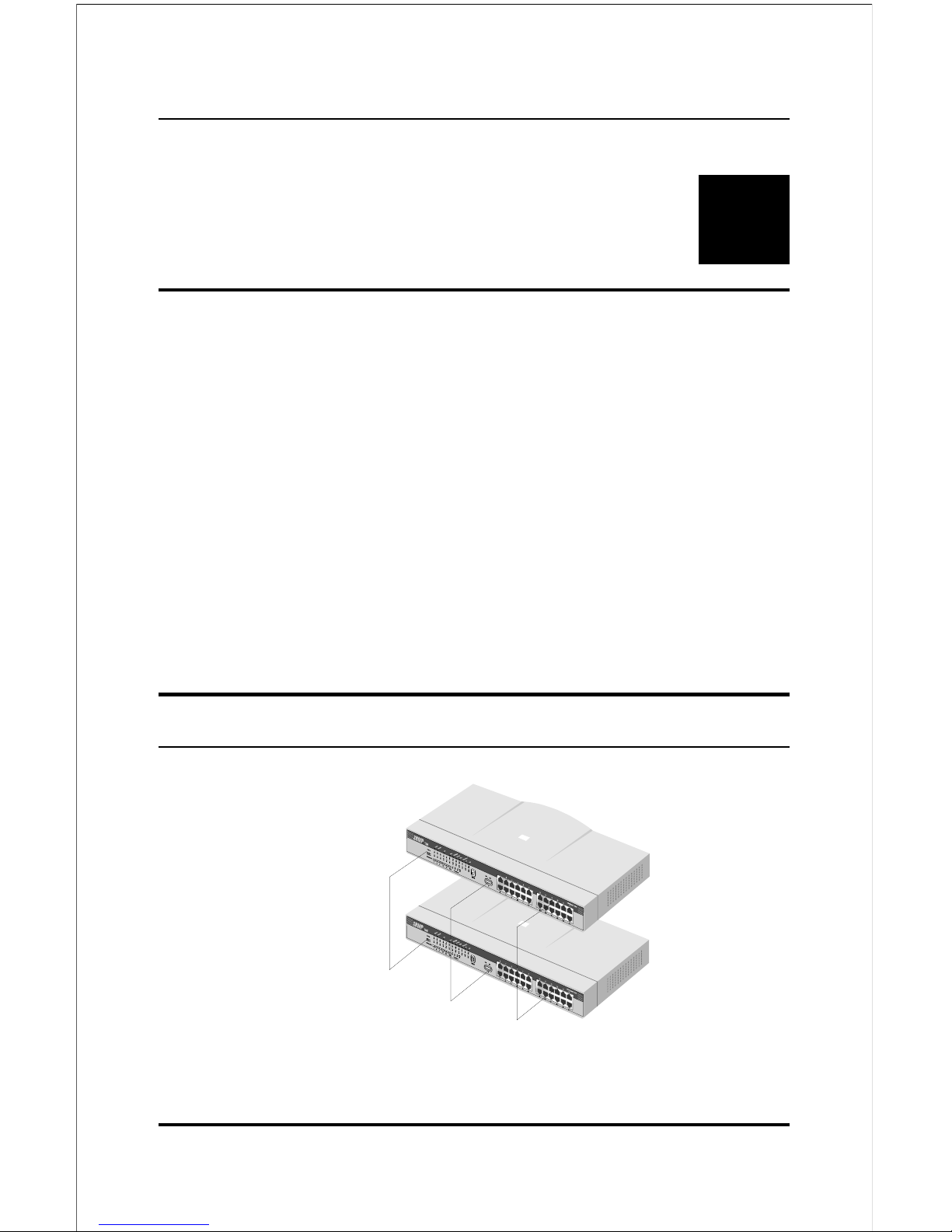
Figures 2-1, 2-2 and 2-3 show the layouts of the front panel, rear panel, and
display of the stackable hubs. Note that there are variations in the
appearances of the front and back panels between hubs in the series. Only
the 24-port models are depicted in this User's Guide.
Front and Back Panel Layouts
Uplink Switch
10BASE-T Port
s
LED Panel
Figure 2 -1 Front Panel Layout
Setting Up the Hub 2-1
Page 16
10BASE-T Stackable Hubs
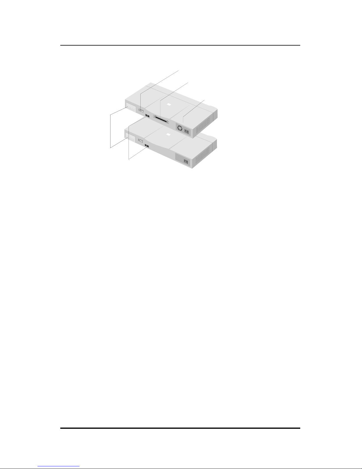
AUI Connector
Daisy-chain Port
C
onsole Port
Removable Power Supply
Expansion Module Port
Figure 2 -2 Back Panel Layout
The following components are found on the front and back panels of the
hubs:
♦ Ethernet Ports
Used for connecting the hub to network devices using 10BASE-T
shielded or unshielded twisted-pair cable. The X label marked on each
port means the ports are MDI-X ports, which connect to workstations and
servers using straight-through cables and to other hubs using crossover
cables.
♦ Port 1 Uplink Switch
Converts port 1 to an uplink port to allow you to connect the hub to an
Ethernet switch or another hub with an ordinary straight-through cable
instead of a modified crossover cable.
♦ RS-232 Console Port (manageable models only)
Used to connect the master hub to a network management station for out-
of-band communication, or for simple management using the console
interface. The console port has a standard 9-pin RS-232 female
connector.
2-2 External Features and Indicators
Page 17
10BASE-T Stackable Hubs
♦ AUI Port
Used when connecting the hub to a 10BASE5 "thick Ethernet" backbone,
or to other types of Ethernet media. The recessed AUI port
accommodates most standard transceivers (also known as Media Access
Units or MAUs), allowing the transceiver to be safely and conveniently
tucked away.
♦ Daisy-chain Port
The daisy-chain port consists of one set of two RJ-45 connectors. It
allows you to connect Intelligent hubs together into a stack of up to 8
hubs with a maximum of 192 10BASE-T ports.
♦ Expansion Module Port (manageable models only)
Used for adding optional expansion modules to the hub, such as the
10/100Mbps switch module.
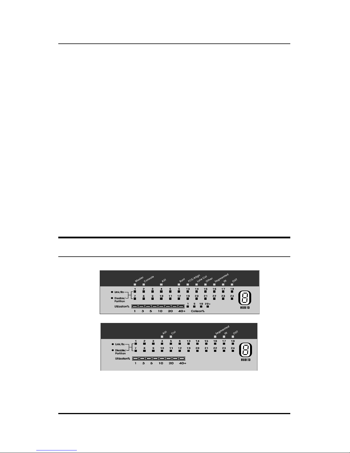
Front Panel Indicators
Figure 2 -3 Indicator Display
External Features and Indicators 2-3
Page 18

10BASE-T Stackable Hubs
The hub's front panel display features the following indicators:
♦ Port Status Indicators
Each of the ports has an LED status indicator for reporting its link and
activity status, and showing whether or not it has been partitioned.
The port status indicators always come on when the hub is powered on.
After the POST (Power-On Self Test) is completed, they normally go off.
The following describes each indicator and the meaning of each
condition:
◊ Link
The indicator of a port lights green when the port is connected to a
powered Ethernet station. If the station to which the hub is connected
is powered off, or if there is a problem with the link, th e indicator is
off.
◊ Receive
The indicator of a port blinks green when the port is currently
receiving packets on the connected segment. Upon reception, each
data packet will be transmitted through all other connected ports on
the hub (or in the hub stack).
◊ Auto-partition
The indicator of a port blinks amber when the port is automatically
partitioned due to an abnormal network condition.
A port is temporarily partitioned when too many line errors or too
many collisions are detected on the port. While the segment is
automatically partitioned, the port continues to receive data. However,
data is not transmitted out of the segment (from the port). When the
problem is corrected or a valid data packet is received from the port,
the port is automatically reconnected.
2-4 External Features and Indicators
Page 19

10BASE-T Stackable Hubs
◊ Manual Partition
The indicator of a port lights amber continually when the port is
manually partitioned.
Manually partitioning a port has the same effect as automatic
partitioning, except that you must also manually re-enable it. You can
choose to manually partition a port even if there is nothing wrong
with it, for example to prevent a certain device from accessing the
network or to reduce network traffic.
No incoming packet transmission can occur on a manually partitioned
port. Ports can be partitioned and re-enabled using an SNMP-based
network management system, or using the console menu interface.
♦ Master (manageable models only)
The Master indicator lights to indicate that the master hub is serving as an
active master.
♦ Console (manageable models only)
The master hub's Console or Out-Of-Band indicator will light to indicate
whether the hub's RS-232 console port is being used for the console
interface or for out-of-band network management using the SLIP
protocol. The mode of the console port may be set using the console
interface or using an SNMP-based network management system.
♦ FCS/Align (manageable models only)
The FCS (Frame Check Sequence)/Align indicator lights amber to
indicate that data packets have been corrupted during transmission. An
FCS error occurs when a data packet fails an internal consistency check.
An alignment error occurs when the bits in a packet don't add up to a
whole number of bytes.
External Features and Indicators 2-5
Page 20

10BASE-T Stackable Hubs
♦ Late Col (manageable models only)
The Late Col indicator lights when a collision is detected that happened
after the 512th bit of a frame. Late collisions may be caused by overly
long delays in the Ethernet network, either due to cable that is too long or
a repeater (hub) count that is too high.
♦ Runt (manageable models only)
The Runt indicator lights when the hub receives a packet that is too short.
Ethernet packets must be at least 64 bytes long. Runts are often a normal
side effect of collisions.
♦ Other (manageable models only)
The indicator lights amber when other types of Ethernet errors occur.
♦ Utilization %
The utilization bar graph displays the percentage utilization of Ethernet
bandwidth, comparing the amount of data being transmitted over the
network with the maximum amount possible. All received Ethernet
frames are counted, whether they were valid or not. The hub updates this
display every 0.5 seconds.
♦ HUB ID
The HUB ID display indicates the Unit ID of the hub. In a hub stack,
each hub unit should have a unique ID. The hub is capable of
automatically setting the hub ID, freeing you from having to do so.
Using the console interface, you can turn on Group ID flashing, which
will make the hub ID indicator flash off and on. This may be useful for
identifying a specific hub or a hub stack within a large bank of hubs.
♦ Segmented
The Segmented indicator lights when the entire hub has been manually
segmented off from the rest of the network. Normally the hubs are
2-6 External Features and Indicators
Page 21

10BASE-T Stackable Hubs
connected together into a single Ethernet “collision domain” through the
daisy chain connectors on the back. Segmenting a hub places it in its
own collision domain, while allowing it to be managed with the rest of
the stack.
External Features and Indicators 2-7
Page 22

10BASE-T Stackable Hubs
♦ Daisy-chain in/out
The down arrow indicates that another hub in the stack is connected to
the daisy-chain in port of the hub, and the up arrow indicates that another
hub is connected to the daisy-chain out port.
♦ Col Ratio (manageable models only)
The Col Ratio bar graph displays the collision rate on the Ethernet
network, in units of tens of collisions per second. Collisions occur
whenever two or more devices on the network attempt to transmit at the
same time; whenever that happens, all of the devices involved back off
and retransmit after a small delay. An excessive number of collisions can
drastically reduce the bandwidth of the network, and may indicate that the
network is overloaded or that there is some sort of hardware or wiring
problem.
The Col Ratio is only displayed on the manageable hub models; on all
models, however, the Col indicator will blink when a collision occurs.
2-8 External Features and Indicators
Page 23

10BASE-T Stackable Hubs
3
3 SETTING UP T H E HUB
This chapter explains how to choose a place for your hub stack and how to
set up your hubs.
Power and Environmental
Requirements
The hubs feature an auto-selecting 100-240 V, 50-60 Hz power supply unit,
which works in most countries around the world. Before connecting the
supplied power cord to the hub, check to see that the power cord does not
exceed the maximum length allowed in the country of operation. (The power
cord normally included with the device is 1.83m (6ft.) long.) Also, make sure
it is terminated with the proper connector for use with you r particu lar voltage
and current requirements. The cord voltage and current ratings should
conform to the standards of the country where you are using the hub.
When using a 230V power source within the U.S., use a UL-listed power
cord with the following characteristics:
♦ 18 AWG
♦ Type SVT or SJT three-conductor cord
♦ Maximum 15 feet in length
Setting Up the Hub 3-1
Page 24

10BASE-T Stackable Hubs
♦ Tandem blade
♦ Grounding type attachment plug rated at 15 A, 250V
When using a 230V power source outside of the U.S., use a cord with the
following characteristics:
♦ 18 AWG
♦ Grounding attachment plug rated at 15A, 250V
♦ The cord should have the appropriate safety approvals for the country
where the equipment will be installed. It should be marked “HAR.”
Be sure the operating environment for the hub is within the following ranges:
♦ Temperature: 32o to 122oF (0o to 50oC)
♦ Humidity: 5% to 95% (non-condensing)
Power Connection
To connect power, take the following steps.
1. Plug the female IEC connector of the power cable into the power
connector on the back of the hub.
2. Insert the three-pronged plug on the power module cable into a non-
switched, grounded power outlet on a wall, a power strip, or a
grounded extension cord.
3. When you plug in the power cable, verify that the hub performs the
self test to confirm the hub is operating correctly. To power off the
hub, disconnect the male connector from the outlet. Do not disconnect
the female connector from the hub to power off the hub.
3-2 Setting Up the Hub
Page 25
10BASE-T Stackable Hubs
Free-standing Installation
If you are installing the hub as a free-standing unit, apply the four selfadhesive rubber feet to the bottom of the hub chassis. Make sure the bottom
surface of the chassis is clean and dry. Stand the chassis up-on-end and
attach one rubber foot about 1 inch from each corner.
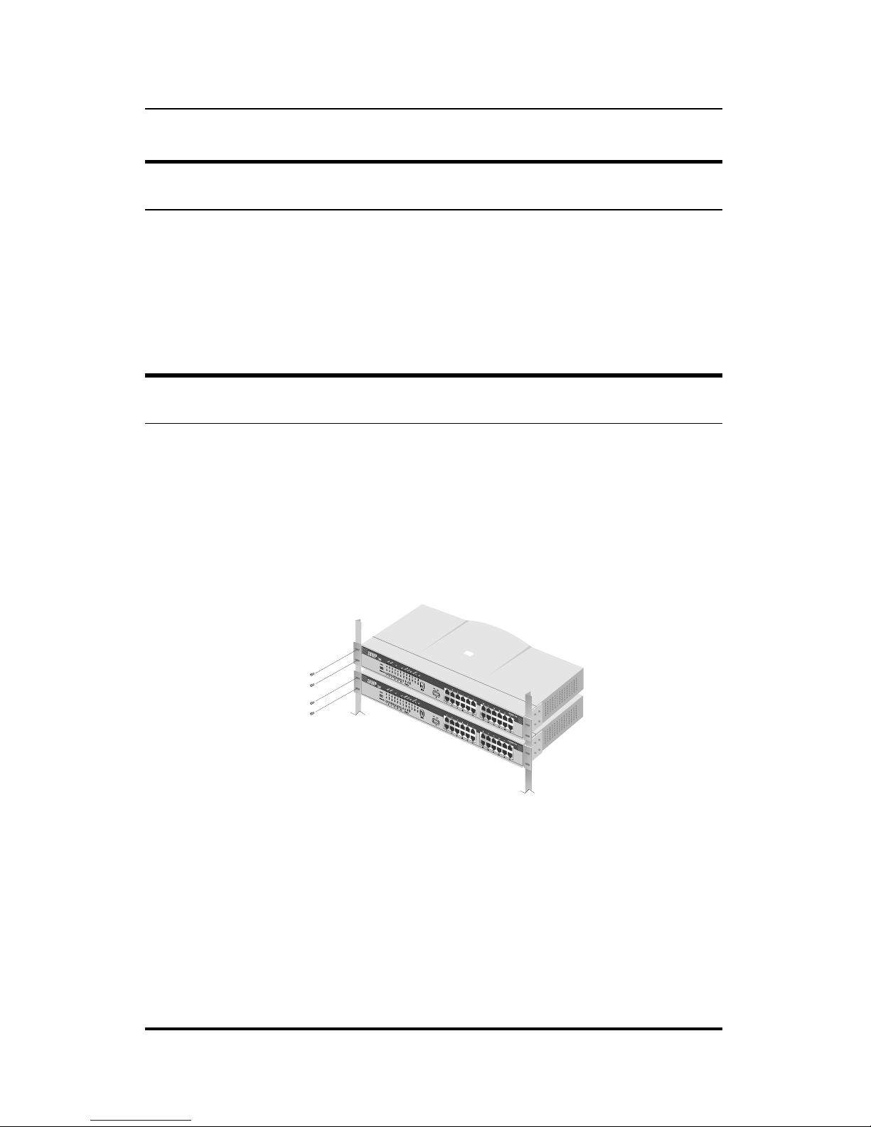
Rack-Mounting
The hubs can be used standalone on a tabletop or shelf, or mounted in a rack.
When mounting the hub stack in a rack, confirm that the rack is an EIA
standard 19-inch rack. For rack mounting convenience, a pair of mounting
brackets is included in the package. Attach the mounting brackets with the
enclosed machine screws, and then mount the hub in the rack using screws
included with the rack.
Figure 3 -1 Rack-Mounting
Setting Up the Hub 3-3
Page 26
10BASE-T Stackable Hubs
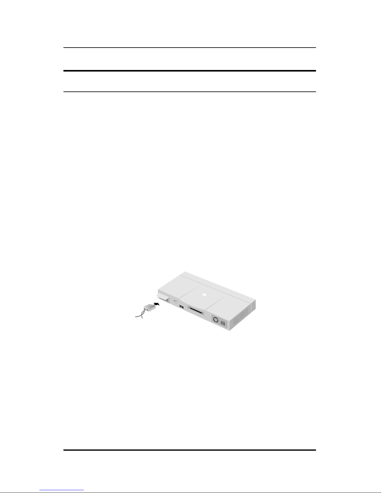
Installing the Transceiver Tray
At the rear of the hub, there is an AUI connector designed for connecting the
hub to various types of Ethernet media such as thick Ethernet coaxial cable
(10BASE5), thin Ethernet coax (10BASE2), or fiber optic cabling (10BASEFL). The AUI connector is recessed, allowing most types of transceivers
(otherwise known as Media Access Units or MAUs) to be installed partially
recessed within the rear panel of the hub. To make inserting and removing
the transceiver easier, a transceiver tray has been included with the hub.
To install a transceiver using the tray, first place the transceiver in the tray,
with the slotted stubs o n the transceiver's male AUI connecto r fitting into the
slots on the front of the tray. Open the door covering the AUI port and slide
the tray and transceiver into the slot until the connection is secure.
Most transceivers should fit within the slot. To accommodate larger
transceivers, insert a standard AUI cable using the tray. In this case, the cable
serves as a short extension to allow the transceiver to be used external to the
hub enclosure.
Figure 3 -2 Installing the Transceiver Tray
3-4 Setting Up the Hub
Page 27
10BASE-T Stackable Hubs
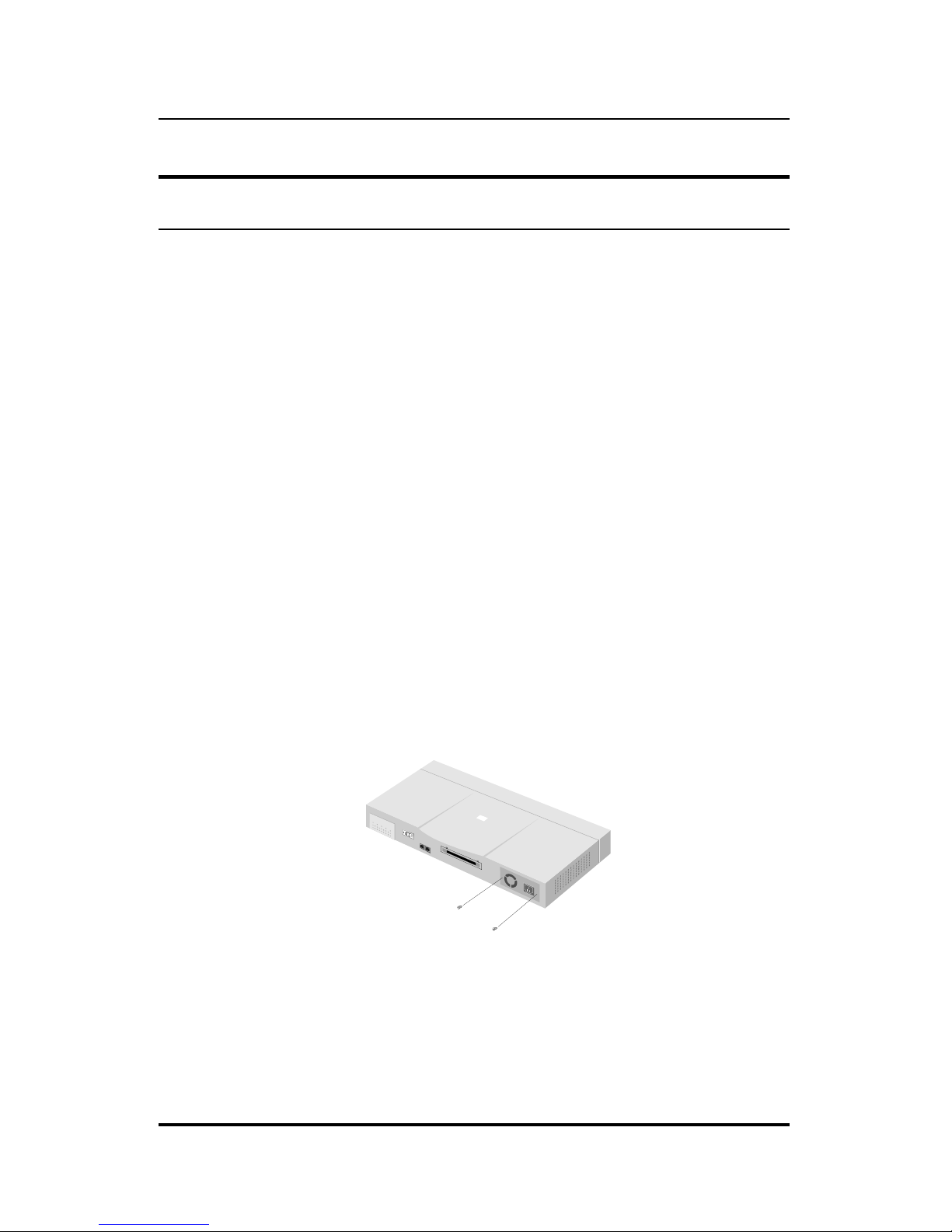
Replacing the Power Supply
The hub comes with a removable power supply for easy replacement. In the
unlikely event that the power supply fails or is damaged, follow the steps
below to replace the power supply.
1. Disconnect the power cord from the AC outlet.
2. Disconnect the power cord from its connector on the rear of the hub.
3. Using a Phillips screwdriver, remove the screws securing the power
supply to release the unit.
4. Remove the power supply by sliding it out the rear of the chassis. Do
not plug in the power supply when it is outside the chassis! Doing
so could cause personal injury or damage to the power supply.
5. Slide the replacement power supply into the chassis, engaging the
connector carefully.
6. Attach the power cord to the connector of the power supply and
connect the other end of the power cord to the AC supply source.
Figure 3 -3 Replacing the Power Supply
Setting Up the Hub 3-5
Page 28

Page 29

10BASE-T Stackable Hubs
4
4 BUILDING HUB
STACKS
You can combine up to eight hubs in the Intelligent Series into a single
manageable hub stack. Building a hub stack has two advantages:
♦ All of the hubs can be managed as a single unit using a network
management system or the console interface. Up to 192 10BASE-T
ports can be controlled and monitored from a single management
screen. Only one master hub is required; less costly slave hubs can be
used for the rest of the stack.
♦ The entire hub stack counts as a single repeater hub when planning
your network. The Ethernet standard requires that there be at most
four repeaters between any two stations on the network. Using the
hub's built in daisy-chain ports allows you to link eight hubs together
without violating the repeater count limitation.
This chapter tells about the various roles hubs in the stack can play, how to
connect the hubs using the Daisy-Chain ports, and how to divide hubs in the
stack into separate segments.
Hub Roles
The series supports both master and slave hubs. In addition, more than one
master hub can be placed in a single hub stack. Therefore, a hub in the stack
Building Hub Stacks 4-1
Page 30

10BASE-T Stackable Hubs
can take on different roles depending on the type of hub it is and its position
in the hub stack.
Position Within the Stack
Hubs in the hub stack are connected using the daisy-chain ports located at the
rear of the hub. Each hub has an IN port and an OUT port. Hubs are daisychained together by connecting the OUT port of one hub to the IN port of the
next hub in the chain. A typical stack arrangement is shown below.
In
Out
Out
Out
In
DaisyChain
In
Figure 4 -1 Typical Stack Arrangement
All hubs connected (directly or indirectly) through the IN port of a hub can
be considered upstream of that hub, and all hubs connected (directly or
indirectly) through the OUT port of the hub can be considered downstream.
If a hub does not have any upstream hubs, it is at the head of the stack.
Master Hub Roles
You can include more than one master hub in a hub stack. This allows you
to continue to manage the hub stack, even if the management agent of one of
the master hubs fails. The hub currently managing the stack is called the
Active Master and other master hubs in the stack are called Standby Masters.
If a master hub is at the head of the stack, it automatically becomes the
Active Master. Otherwise, it will wait for management commands from
4-2 Building Hub Stacks
Page 31

10BASE-T Stackable Hubs
another master hub upstream. If it receives commands from a master hub, it
becomes a Standby Master, controlled by the Active Master. If it does not
receive any commands, or if the Active Master hub fails, it will become the
Active Master.
Note that even if there are more than two master hubs in the stack, the
Standby indicator of the additional master hubs will not light. However, if
the Active Master at the head of the stack fails, the first Standby Master will
become the Active Master, and the next master hub will then become a
Standby Master.
A master hub can only manage hubs that are downstream of it. Therefore,
you should place the hub that you want to serve as the Active Master at the
head of the stack. If you want to use Standby Master hubs, you should place
them directly downstream of the Active Master. Otherwise, you will not be
able to control or monitor any slave hubs upstream of the master hub.
Each master hub has its own IP address. All master hubs respond to SNMP
management commands, though only the Active Master is capable of
controlling and monitoring other hubs. If the Active Master hub fails, then
you will need to use the IP address of the n ew Active Master to manage the
other hubs in the stack.
Slave Hub Roles
Slave hubs can operate standalone or can be a Managed hub controlled by an
(upstream) Active Master hub.
If there are no master hubs in the hub stack, or if the Active Master hub in
the stack fails and there is no Standby Master hub to take its place, the slave
hubs will be Standalone hubs. (In a case where the Master Hub fails, you
should power the slave hubs off and then on again to insure they are in a
valid state before using them as Standalone hubs.) Standalone hubs all have
a Hub ID of 0. As a standalone hub, all ports will be enabled, and settings
such as hub segmenting, intrusion security, etc. will have no effect.
Building Hub Stacks 4-3
Page 32

10BASE-T Stackable Hubs
When there is a working Active Master in the stack, then each slave hub in
the stack will be a Managed hub controlled by the Active Master hub, and
will have its own Hub ID.
Hub ID
Hub ID numbers, displayed on the front of the hub, are determined
automatically by the master hub. When the master hub starts up, it begins to
assign Hub ID numbers to all of the Standby Master and Managed hubs. The
master hub remembers the Hub ID associated with each hub in the stack, and
even if a hub is removed, the other hubs will keep their original Hub IDs.
When you add a new hub to the stack, the master hub will assign it an unused
Hub ID.
Daisy-chaining Hubs into a Hub
Stack
Hubs are daisy-chained together using ordinary 4-pair, Category 5, twistedpair cabling with RJ-45 connectors on each end. A short (30cm) daisy-chain
cable is included with the hub. If you need to make a longer cable, consult
the pinout information in Appendix D. The total length of all the cables,
measured from the first hub in the stack to the last, must not exceed 100
meters.
Normally the master hubs are placed at the top of the stack. The hub you
intend to serve as Active Master should be on top, and any Standby Master
hubs should be immediately below it. Other hubs can be placed in any order
below the master hubs.
Connect a daisy-chain cable from the OUT port of the Active Master hub to
the IN port of the next hub downstream. Each additional cable should go
from the OUT port of one hub to the IN port of the hub below it, as shown
below in Figure 4 -2.
4-4 Building Hub Stacks
Page 33

10BASE-T Stackable Hubs
Figure 4 -2 Daisy-Chaining Hubs
Segmenting Hubs
The emergence of Ethernet switching hub technology has made it more
common to segment local area networks into smaller pieces to reduce
congestion on each segment. This makes it easier to balance network loads,
since a smaller number of devices compete for the 10Mbps bandwidth on
each network segment.
A stack of eight hubs makes network management convenient, but 192
Ethernet stations on a single Ethernet network segment may give slow
response at peak network loads. Therefore, the hub provides a way to
segment hubs from the stack into their own collision domains. Segmenting
hubs requires only a simple management command, and does not require any
hardware or wiring changes. Though the hubs continue to be daisy-chained
together and are managed as a single unit, each hub can either be a part of the
collision domain of the rest of the stack, or can be separated into its own
network segment. These separate segments can be bridged by connecting
them to separate ports of an Ethernet switching hub.
Building Hub Stacks 4-5
Page 34

10BASE-T Stackable Hubs
Figure 4 -3 All Hubs Connected to Ethernet Backbone
Figure 4 -3 shows an unsegmented stack of hubs. All hubs in the stack are in
the same collision domain because they are connected together using the
daisy-chain ports and they have not been segmented.
Figure 4 -4 shows a stack divided into three separate collision domains.
Hubs 4 and 5 are isolated from Collision Domain 1 (hubs 1, 2, and 3) using
the hub segmentation capability, putting them into their own isolated
Collision Domains 2 and 3 respectively. A switch, bridg e or router can be
used to connect the three collision do mains so that traffic can pass between
them, yet keeping them isolated to reduce congestion on each segment.
Without an additional connection, none of the three Collision Domains will
be able to pass traffic across domains, however, using a pass-through cable to
cascade the domains would negate their usefulness as separate segments.
4-6 Building Hub Stacks
Page 35

10BASE-T Stackable Hubs
Figure 4 -4 Three Separate Collision Domains
When a hub is segmented from the rest of the stack, the Segmented indicator
on the front panel display will light. For information about segmenting hubs
using the console interface, see Chapter 6 in this User's Guide. For
information about segmenting hubs using the network management module
for the hub, see the management module's User's Guide.
NOTE: Hub segmentation is controlled by the master
hub. While the hub is performing its Power-On
Self-Test (POST), all hubs in the stack will be
connected together in a single segment. When
the master hub completes its initialization, it will
restore any segmentation of the hubs.
Therefore, if you are using a switch or bridge to
join different segments, be sure to enable the
IEEE 803.1d Spanning Tree Protocol to
prevent temporary network loops.
Building Hub Stacks 4-7
Page 36

Page 37

10BASE-T Stackable Hubs
5
5 NETWORK
CONNECTIONS
Once you have set up your hubs and connected them into a stack, you are
ready to connect network stations, and to connect your hub to the rest of your
Ethernet network. This chapter tells how to connect workstations to the hub,
and the hub to the other hubs and network components on your local area
network.
Connecting Stations to the Hub
The hub's RJ-45 connectors are used for directly connecting the hub to
network devices using 10BASE-T shielded or unshielded twisted-pair cable
(STP or UTP). The X label marked on each port means the ports are MDI-X
ports, which connect to workstations and servers using straight-through
cables and to other hubs using crossover cables.
To connect to a network station, use ordinary Ethernet twisted pair cable
(Category 3 or better), either directly or through a central wiring patch block.
The cable can be a maximum of 100 meters long. Only two wire pairs in the
cable are used for 10BASE-T Ethernet.
One wire pair should be connected to pins 1 and 2 of the connector, and
another wire pair should be connected to pins 3 and 6. Detailed pinout
information for 10BASE-T connectors can be found in Appendix D.
Network Connections 5-1
Page 38

10BASE-T Stackable Hubs
Plug the RJ-45 connector at one end into the network station, and the other
end into a free 10BASE-T port on the front of the hub. When both the hub
and the device at the other end of the connection are turned on, and the cable
is connected at both ends, then the Link indication for the port should light.
If it does not, then:
1. Be sure that the connectors are seated correctly at both ends of the
cable.
2. Check the continuity of the wires in the cable, as well as the pin
assignments on the RJ-45 connectors.
3. Be sure that the network station to which the port is connected is
plugged in and powered on.
4. Check that the right type of cable is connected to the port and that the
uplink switch is set correctly.
Figure 5 -1 Connecting Stations to the Hubs
5-2 Network Connections
Page 39

10BASE-T Stackable Hubs
Cascading Hub Stacks
If you need to expand your network beyond an eight-port stack, or you need
to connect your hub to other parts of your network, you can cascade it using
several different network media, including 10BASE-T twisted-pair cabling,
10BASE2 thin coaxial cabling, 10BASE5 thick coaxial cabling, and FOIRL
or 10BASE-FL fiber optic cabling.
When planning your network, it is important to keep the Ethernet
configuration rules in mind. In particular, be sure that there are no more than
four repeaters (including hubs or hub stacks) between any two stations on the
network. Also, be careful that none of the cable links exceed the maximum
length for that type of cable. If you need to exceed the repeater limit, you
can use a bridge or Ethernet Switch to divide the network into separate
collision domains.
Using Twisted-pair Cabling
One way you can connect hubs or 12hub stacks together is by using ordinary
twisted-pair cabling. This is the simplest method, though it has the
disadvantages that the distance between hub stacks can be at most 100
meters, and all but the first and last hubs require two RJ-45 ports each for the
cascade connections.
Twisted-pair cabling is also usually used to connect repeater hubs to Ethernet
switching hubs.
There are two different ways of cascading hubs using 10BASE-T cabling.
The first way is to use a crossover cable, which connects the transmit of one
hub to the receive of the other, and vice versa. A crossover cable can be
made easily, as explained in Appendix D.
A more convenient method is to use the hub's Uplink switch. The Uplink
switch lets you use Port 1 as either an ordinary MDI-X port for connecting to
a server or workstation, or as an MDI port for connecting to another hub.
Network Connections 5-3
Page 40

10BASE-T Stackable Hubs
This means you can cascade to another hub using an ordinary straightthrough twisted-pair cable.
Figure 5 -2 Uplink Switch Setting
When using this method, set the Port 1 Uplink switch to MDI, connect one
end of the straight-through cable Port 1 of the hub, and connect the other end
of the cable to an ordinary (non-uplink) port on the other repeater hub or
Ethernet switch.
Don't try to cascade more than four repeater hub stacks in a line using
twisted-pair cabling. Instead, use a multilevel cascading sch eme as discussed
in the Multilevel Cascading section below.
Figure 5 -3 Connection Through Port 1
5-4 Network Connections
Page 41

10BASE-T Stackable Hubs
Using Thin Coaxial Cabling
With the addition of a 10BASE2 transceiver connected to the AUI port at the
rear of the hub (as described in Chapter 3), you can cascade the hub to other
hubs or stations using thin coaxial cabling. This method of cascading hubs
gives additional flexibility over using twisted-pair cable, since you can
cascade up to thirty hubs on a single thin coaxial cable segment. The entire
coaxial segment may be up to 185 meters long.
Each device on the thin coax segment needs to have a BNC port or use a
10BASE2 transceiver. The cables should be connected to the BNC ports
using BNC T-connectors, and there should be 50 ohm terminating resistors
on each end Make sure that you leave at least 0.5 meters of coaxial cable
between any two nodes on the thin coaxial cable segment.
Using Fiber or Thick Coaxial Cabling
Similarly, transceivers connected to the AUI port can be used for connecting
thick coax Ethernet (10BASE5) or fiber optic cabling (FOIRL or 10BASEFL) to the hub.
A thick Ethernet trunk can be up to 500 meters long (preferably a single
piece of cable), and should have 50 ohm terminating resistors at each end.
The cable shield should be grounded at one end. 10BASE5 transceivers
usually tap directly into the coaxial cable; taps should be placed at 2.5 meter
intervals, and you can have a maximum of 100 taps on a single cable
segment. You can connect the transceiver to the hub's AUI port using an
AUI cable up to 50 meters long.
Using a fiber optic transceiver, you can link to another hub or hub stack up
1000 meters away using FOIRL (Fiber Optic Inter-Repeater Link), or up to
2000 meters away using 10BASE-FL. The fiber optic transceiver should be
inserted into the AUI port. Two fiber optic cables are required ; the transmit
line of each transceiver should be connected to the receive connector of the
other.
Network Connections 5-5
Page 42

10BASE-T Stackable Hubs
When connecting a transceiver to the hub, the transceiver's SQE (heartbeat)
function should be disabled.
Multilevel Cascading
Hubs can be cascaded in multiple levels, provided no path between stations
on the network goes through more than four repeaters. For example, a
backbone level of hubs can be connected in a bus using 10BASE2 cabling,
and second-level workgroup hubs can be connected to the backbone hubs
using twisted-pair cabling. This type of network layout allows a greatly
expanded number of network nodes without sacrificing manageability.
Figure 5 -4 Multilevel Cascading
5-6 Network Connections
Page 43

10BASE-T Stackable Hubs
6
6 USING THE CONSOLE
INTERFACE
Your Intelligent stackable Ethernet hub supports a console management
interface that allows you to set up and control your hub, either with an
ordinary terminal (or terminal emulator), or over the network using the
TCP/IP Telnet protocol. You can use this facility to perform many basic
network management functions. In addition, th e console program will allow
you to set up the hub for management using SNMP-View or another SNMPbased network management system. This chapter describes how to use the
console interface to access the hub, change its settings, and monitor its
operation.
Connecting to the Hub
You can use the console interface by connecting the hub to a VT100compatible terminal or a computer running an ordinary terminal emulator
program (e.g., the terminal program included with the Windows operating
system) using an RS-232C serial cable. Your terminal parameters will need
to be set to:
♦ VT-100/ANSI compatible
♦ Arrow keys enabled
♦ 9600 baud
Using the Console Interface 6-1
Page 44

10BASE-T Stackable Hubs
♦ 8 data bits
♦ No parity
♦ One stop bit
You can also access the same functions over a Telnet interface. Once you
have set an IP address for your hub, you can use a Telnet program (in a VT100 compatible terminal mode) to access and control the hub. All of the
screens are for the most part identical, whether accessed from the console
port or from a Telnet interface.
Console Usage Conventions
The console interface makes use of the following conventions:
1. Items after a colon”:” are read-only values, displayed for
information purposes. The cursor cannot be moved to these items.
2. Items in <angle brackets> can be toggled on or off using the space
bar.
3. Items in [square brackets] can be changed by typing in a new value.
You can use the backspace and delete keys to erase characters behind
and in front of the cursor.
4. The up and down arrow keys, the left and right arrow keys, and the
tab key, can be used to move between selected items. The currently
selected item will be shown in reverse video.
5. Items in UPPERCASE are commands. Moving the selection to a
command and pressing Enter will execute that command.
6-2 Using the Console Interface
Page 45

10BASE-T Stackable Hubs
Logging In to the Hub Console
The Intelligent Series master hubs support user-based security that can allow
you to prevent unauthorized users from accessing the hub or changing its
settings. This means that before you can access the functions of the hub, you
will need to first log into the hub, giving a password. This section tells how
to log onto the hub, and how to change your password.
Logging In
When you first connect to the hub, it will display the login screen:
Figure 6 -1 Login Screen
To log in,
1. Type in your user name and press Enter.
2. Type in your password and press Enter.
Using the Console Interface 6-3
Page 46

10BASE-T Stackable Hubs
3. With the cursor on the OK selection, press Enter. The main menu
screen will be displayed.
NOTE: When the hub is shipped from the factory, the
default user name is SNMP-T and the default
password is also SNMP-T. You will need to
use this user name and password when you
first set up your hub or if you have completely
reset the hub settings using the
Factory
Reset NVRAM to Default Value
menu
selection. Be sure to change this user name
and password (as described below) to
protect the security of your hub.
There are two levels of user privileges: Super User and General User. The
default user (SNMP-T) has Super User privileges. Some menu selections
available to users with Super User privileges may not be available to General
Users. The main menu shown below is the menu for users with Super User
privileges:
Figure 6 -2 Main Menu
6-4 Using the Console Interface
Page 47

10BASE-T Stackable Hubs
Changing your Password
To change your user password:
1. Choose User Account Change from the main menu.
2. Choose Change Password.
Figure 6 -3 Change Password
1. Type in your user name and press Enter.
2. Type in your old password and press Enter.
3. Type in the new password you have chosen, and press Enter. Type in
the same new password in the following blank to verify that you have
not mistyped it.
4. Choose the SAVE command to let the password change take effect.
5. Choose EXIT to exit this screen.
Using the Console Interface 6-5
Page 48

10BASE-T Stackable Hubs
This method can also be used by a Super User to change another user’s
password.
Setting up the Master Hub
This section describes the settin gs you will n eed to chan ge to allo w you to be
able to manage the hub from an SNMP-based Network Management System
such as SNMP-View, or to be able to access the hub using the Telnet
protocol.
TCP/IP Settings
The hub needs to have a TCP/IP address assigned to it so that the network
management system or Telnet client can find it on the network. The TCP/IP
Parameters Configuration Menu allows you to change the settings for the two
different interfaces used on the hub: the Ethernet interface used for in-band
communication, and the SLIP interface used over the console port for out-ofband communication.
Each of the fields on this menu takes effect the next time the system is
restarted. Fields that can be set include:
♦ IP Address: determines the IP address used by the hub for receiving
SNMP and Telnet communications. Should be of the form
xxx.xxx.xxx.xxx, where each xxx is a number (represented in decimal)
between 0 and 255. This address should be a unique address on a
network assigned to you by the central Intern et authorities. The same
IP address is shared by both the SLIP and Ethernet network interfaces.
♦ Subnet Mask: bitmask that determines the extent of the subnet that
the hub is on. Should be of the form xxx.xxx.xxx.xxx, where each xxx
is a number (represented in decimal) between 0 and 255. If no
subnetting is being done, the value should be 255.0.0.0 for a Class A
network, 255.255.0.0 for a Class B network, and 255.255.255.0 for a
Class C network.
6-6 Using the Console Interface
Page 49

10BASE-T Stackable Hubs
♦ Default Gateway: IP address that determines where frames with a
destination outside the current subnet should be sent. This is usually
the address of a router or a host acting as an IP gateway. If your
network is not part of an internetwork, or you do not want the hub to
be accessible outside your local network, you can leave this field
blank.
♦ Send BOOTP Request Upon Power Up: determines whether the
hub should send out a BOOTP broadcast request when it is powered
up. The BOOTP protocol allows IP addresses, network masks, and
default gateways to be assigned on a central BOOTP server; if this
option is set the hub will first look for a BOOTP server to provide it
with this information before using the supplied setting s.
Figure 6 -4 TCP/IP Parameters
Using the Console Interface 6-7
Page 50

10BASE-T Stackable Hubs
Out-of-band management and console
settings
You can use the Out-of-Band/Console Setting menu to choose whether to use
the hub’s RS-232C serial port for console management or for out-of-band
TCP/IP communications using SLIP, and to set the bit rate used for SLIP
communications.
The following fields can be set:
♦ System Restart Out-of-Band Baud Rate: determines the serial port
bit rate that will be used the next time the hub is restarted. Applies
only when the serial port is being used for out-of-band (SLIP)
management; it does not apply when the port is used for the console
port. Available speeds are 1200, 2400, 9600, and 19200 bits per
second.
♦ Out-of-Band Dial Up Phone Number: stored as a reference for the
benefit of the system manager; does not actually cause the hub to dial
out.
♦ System Restart Serial Port Setting: determines whether the serial
port should be used for out-of-band (SLIP) management or for
console management, starting from the next time the hub is restarted.
6-8 Using the Console Interface
Page 51

10BASE-T Stackable Hubs
Figure 6 -5 Out-of-Band/Console Setting Menu
Software Updates
The hub is capable of obtaining its boot-time configuration information, as
well as updated versions of its internal firmware, using TFTP (the Trivial
File Transfer Protocol) and BOOTP (the BOOTstrap Protocol). You can use
the Software Update menu to control this feature.
The fields you can set in this menu are:
♦ Software Update Determines whether or not the hub will try to look
for a configuration file over the network. If set to Disable, none of
the fields below have any effect.
♦ Software Update Mode Set to either Network or Out-of-band.
Determines whether the configuration file should be obtained through
the Ethernet network or through the console port.
♦ Boot Protocol Set to either TFTP ONLY or
BOOTP&TFTP.
Applies only if the S/W Update Control is enabled.
Using the Console Interface 6-9
Page 52

10BASE-T Stackable Hubs
♦ Boot Server IP Address The IP address of the TFTP server where
the configuration file is located. This entry is used only if the S/W
Update Control is enabled and your boot protocol is
tftp only; if
you are using
bootp-tftp mode, or if Send BOOTP Request on
Power Up is enabled, the address will be obtained from the BOOTP
server.
♦ Boot File Name The pathname of the configuration file on your
TFTP server. If you are using SNMP-View as your TFTP server, this
is the pathname of the
.CFG file on your hard disk. This entry is
used only if your boot protocol is TFTP ONLY; if you are using
BOOTP&TFTP mode, or if Use Bootp to get IP after start up is
enabled, the pathname will be obtained from the BOOTP server.
For more information about SNMP configuration files, consult Appendix C.
For detailed information about using the TFTP and BOOTP servers, consult
the SNMP-View User’s Guide.
Figure 6 -6 Software Update Menu
6-10 Using the Console Interface
Page 53

10BASE-T Stackable Hubs
SNMP Information
The System Configuration Menu screen shows various pieces of information
about your hub, and allows you to set the System Name, System Location,
and System Contact. These settings can be retrieved from the hub using
SNMP requests, allowing these settings to be used for network management
purposes. Each of these fields can contain up to 64 characters:
♦ System Name: corresponds to the SNMP MIB II variable
system.sysName, and is used to give a name to the hub for
administrative purposes. The hub’s fully qualified domain name is
often used, provided a name has been assigned.
♦ System Location: corresponds to the SNMP MIB II variable
system.sysLocation, and is used to indicate the physical
location of the hub for administrative purposes.
♦ System Contact: corresponds to the SNMP MIB II variable
sysContact, and is used to give the name and contact information
for the person responsible for administering the hub.
Figure 6 -7 System Configuration Menu
Using the Console Interface 6-11
Page 54

10BASE-T Stackable Hubs
The System Configuration Menu also contains the Console/Telnet Display
Timeout parameter, which determines how long the console may sit idle
before the user is “logged out.”
SNMP Traps
The hub sends out SNMP traps to network management stations whenever
certain exceptional events occur, such as when the hub is powered on or
when an SNMP request is made using an unknown community name. The
hub allows traps to be routed to up to four different network management
hosts.
Figure 6 -8 SNMP Trap Manager Menu
The following trap parameters can be set:
♦ IP Address: gives the IP address of the network management station
to receive the trap
♦ SNMP Community String: determines the SNMP community name
to be included in the trap request.
6-12 Using the Console Interface
Page 55

10BASE-T Stackable Hubs
♦ Status: determines whether this trap entry is valid or invalid. You
can delete an entry by changing its status to Invalid.
SNMP Security (Community Names)
SNMP (version 1) implements a rudimentary form of security by requiring
that each request include a community name. A community name is an
arbitrary string of characters used as a “password” to control access to the
hub. If the hub receives a request with a community name it doesn’t
recognize, it will trigger an authentication trap.
The SNMP allows up to four different community names to be defined, and
the access rights for each community can be separately set to either read only
or read/write. The community names
public and private are defined
by default; you can change these names in addition to adding others. You
will need to coordinate these names with the co mmunity name settings you
use in your network management system.
Figure 6 -9 SNMP Manager Setting Menu
Using the Console Interface 6-13
Page 56

10BASE-T Stackable Hubs
Adding and Deleting Users
Access to the console, whether using the console port or via Telnet, is
controlled using a user name and password. Up to three of these user names
can be defined. One user, named SNMP, is defined by default; this user
name can be removed if desired. The console interface will not let you delete
the current logged-in user, however, in order to prevent accidentally deleting
all of the users with Super User privilege and making it impossible to change
important hub settings.
Only users with the Super User privilege can add new and delete users. To
add a new user:
1. Choose User Account Change from the main menu.
Figure 6 -10 User Account Change Menu
1. Choose Create New User from the User Account Change menu.
2. Enter the new user name, and assign an initial password. Determine
whether the new user should have Super User or General User
privileges.
6-14 Using the Console Interface
Page 57

10BASE-T Stackable Hubs
Figure 6 -11 Create New User
1. Choose SAVE and press Enter to let the user addition take effect.
2. Choose EXIT to leave the Create New User menu.
To delete a user,
1. Choose User Account Change from the main menu.
2. Choose Delete Users from the User Account Change menu.
3. Toggle the Delete field of the user you wish to remove to Yes.
Using the Console Interface 6-15
Page 58

10BASE-T Stackable Hubs
Figure 6 -12 Delete User
1. Choose SAVE and press Enter to let the user addition take effect.
2. Choose EXIT to leave the Delete Users menu.
Hub Stack Configuration
Several important hub parameters useful in the day-to-day management of
the hub can be viewed and controlled using the Group Configuration,
Primary/Backup Master Menu, and Port State menus.
Primary and Backup Master Hubs
The Primary/Backup Hub screen, accessible from the Network Monitoring
menu, is used to display the status of each of the master hubs in the stack.
The primary master hub is labeled Primary Master, backup master hubs are
labeled Backup Master, and non-functioning master hubs are labeled Down.
6-16 Using the Console Interface
Page 59

10BASE-T Stackable Hubs
Figure 6 -13 Primary/Backup Master Menu
Controlling Hubs in the Hub Stack
The Group Configuration Menu screen, found within the Network
Monitoring menu, displays information about each of the hubs in the stack,
and allows you to make the Hub ID indicator flash.
The items displayed on this screen are:
♦ Group ID: indicates which hub (group) is being displayed.
♦ Group Serial Number: gives the serial number of the displayed hub.
♦ Group Description: gives a description of the given hub, showing
how many ports it has and what options are available, such as whether
or not it is a master hub.
♦ Group Role: shows what role the hub is currently serving in the hub
stack (Primary Master, Backup Master, or Slave).
Using the Console Interface 6-17
Page 60

10BASE-T Stackable Hubs
♦ Group Port Capacity: shows the total number of controllable ports
(includes the UTP ports, AUI ports, an internal management port,
etc.)
♦ Group Hardware Revision: shows the design version of the hub
hardware.
♦ Group Status: shows whether the hub is up or down.
♦ Group Last Oper Change: shows at what time the hub was last
added to or removed from the stack. The format is hh:mm:ss.xx, with
hh representing hours since the master hub was powered on, mm the
minutes, ss the seconds, and xx representing 100ths of a second.
♦ Group ID LED Flash Control: a toggle allowing you to turn Group
ID flashing on or off. You can turn on Group ID flashing for a
particular hub in order to help you find that hub within a large bank of
hubs.
Figure 6 -14 Group Configuration Menu
6-18 Using the Console Interface
Page 61

10BASE-T Stackable Hubs
You can use the PREV GROUP and NEXT GROUP commands to switch to
another hub, or you can enter the hub’s Group ID number directly into the
Group ID field.
Controlling Individual Ports
The Port State Menu, accessible from the Network Monitoring menu, allows
you to view the status of individual ports and to control their settings. The
available settings are:
♦ Group ID: determines which hub’s ports are displayed.
♦ Port ID: determines which port is displayed. Ports 13–16 on the 12-
port hubs, and ports 25–28 on the 24-port hubs, represent the daisy
chain ports, the external AUI connector, the internal expansion port,
and the management port, respectively.
♦ Link Test: displays Up if there is a station connected to the port, and
Down otherwise.
♦ Link Test State: toggle control used for controlling whether or not
the port requires link pulses. If this field is set to Enable, th e port will
check for link pulses, and will only transmit if there is a good link to
another station. If the field is set to disabled, Link Test will always
display Up, the link indicator will always be lit, and the hub will
always transmit data to the port whether a station is connected or not.
♦ Receive Polarity: displays Normal if the polarity of the port’s receive
lines is normal, and Reversed if the two receive lines have been
swapped.
♦ Polarity Reversal: this toggle determines whether or not the hub will
do automatic polarity reversal on the port. If enabled, the hub will
automatically reverse the polarity of reversed signals. If disabled, the
hub will repeat signals received over that port with reversed polarity.
Using the Console Interface 6-19
Page 62

10BASE-T Stackable Hubs
♦ Auto Partition: displays On if the port has been automatically
partitioned off from the rest of the network due to excessive errors,
and Off if the port is operating normally.
♦ Admin State: this toggle determines whether the port should be
enabled or disabled (manually partitioned). Setting the Admin State
to Disabled will isolate the port from the rest of the network.
Figure 6 -15 Port State Menu
You can use the PREV GROUP and NEXT GROUP commands to switch to
another hub, or the PREV PORT and NEXT PORT commands to switch to
another port. You can also enter the port’s Group ID and Port ID numbers.
Segmenting Hubs
Normally, all hubs in the stack are connected together into a single Ethernet
“collision domain” through the daisy-chain connections. However, in some
applications you may want to separate the hubs into separate collision
domains, while keeping them in the same stack for management purposes.
For instance, you may want to segment your network by connecting separate
workgroups to separate segmented hubs in the stack, and bridge the segments
together using a switching hub.
6-20 Using the Console Interface
Page 63

10BASE-T Stackable Hubs
To segment an individual hub from the rest of the stack:
1. Enter the Port State Menu Screen, accessible from the Network
Monitoring Menu.
2. Select the Group ID of the hub you wish to segment.
3. Select Port 25 for the 24-port hub models, or Port 13 for the 12-port
hub models. This port number represents the hub’s Ethernet link to
the daisy chain.
4. Change the Admin State of the hub to Disabled.
5. Move the cursor to SAVE and press Enter. The Segmented indicator
on the front panel should light, indicating that the hub is now in a
separate collision domain.
More information on segmenting hubs can be found in Chapter 4.
Monitoring the Hub Stack
The hub supports several monitoring functions, allowing you to keep
statistics on the operation of each port, each hub, and the entire network
segment, as well as to monitor the addresses of the packets received on each
port.
Displaying Segment, Group, and Port
Statistics
The hub stack collects Ethernet transmission statistics for each individual
port, each hub in the stack, and the Ethernet segment as a whole. You can
Using the Console Interface 6-21
Page 64

10BASE-T Stackable Hubs
choose which to view through the Statistics menu, accessible from the
Network Monitoring menu.
Figure 6 -16 Network Monitoring Menu
The statistics shown are the same for each of these selections. The statistics
displayed are:
♦ Too Long Frame: counts frames longer than the 1518-byte (octet)
limit set by the Ethernet standard. This is likely caused by a software
problem.
♦ Very Long Event: counts events where a signal is received longer
than the jabber lockup protection timer (4–7.5 ms). This may indicate
noise on the line or a bad Ethernet interface.
♦ Short Event: counts events where less than 10 bytes are received and
the frame start delimiter is invalid, or where the start frame delimiter
is valid but less than 2 bytes are received. This may indicate noise on
the line.
♦ Late Event: counts collisions that occur at or after the 64
th
byte
(octet) in the frame. This may indicate that delays on your Ethernet
6-22 Using the Console Interface
Page 65

10BASE-T Stackable Hubs
are too long, and you have either exceeded the repeater count or cable
length specified in the Ethernet standard.
♦ Runt Frame: counts frames shorter than the 64-byte (octet) minimum
defined by the Ethernet standard. These are usually caused by
collisions.
♦ Collision: counts collisions on the Ethernet segment.
♦ FCS Error: counts otherwise valid frames that fail the CRC check.
♦ Alignment Error: counts otherwise valid frames that did not end on a
byte (octet) boundary
♦ Interframe Gap: counts frames sent too close behind the previous
frame; a min imu m o f 8±1 microseconds of carrier is required between
frames.
♦ Jabber: counts frames longer than the maximum 1518 bytes (octets)
with either bad framing or an invalid CRC.
♦ Auto Partition: counts events where the port was partitioned off from
the rest of the network due to excessive errors.
♦ Fragment: counts packets less than 64 bytes with either bad framing
or an invalid CRC. These are normally the result of collisions.
♦ DRM (Data Rate Mismatch): counts events where there is a
frequency mismatch between the received signal and the hub’s
internal clock. This may indicate a hardware problem in the hub or in
an Ethernet interface.
♦ SFD Missing: counts frames longer than 10 bytes without a valid
Start of Frame Delimiter.
♦ Readable Frame: counts valid frames.
♦ Multicast Frame: counts valid frames that are sent to multicast
Ethernet addresses.
Using the Console Interface 6-23
Page 66

10BASE-T Stackable Hubs
♦ Broadcast Frame: counts valid frames that are broadcast to all
stations on the network.
♦ 64 Octs, 65-127 Octs, 128-255 Octs, 256-511 Octs, 512-1023 Octs,
1024-1518 Octs: Counts frames of various length ranges, both valid
and invalid.
♦ Readable Oct: counts the total number of bytes (octets) included in
valid (readable) frames.
♦ Total Errors: sum of the FCS Error, Alignment Error, Too Long
Frame, Short Event, Late Event, Very Long Event, and Data Rate
Mismatch counters.
Figure 6 -17 Port Statistics Display
For the Segment Statistics display, an additional item is displayed:
♦ Interhub Collision: counts the number of collisions that occur on the
hub stack’s internal management bus.
You can use the PREV GROUP, NEXT GROUP, PREV PORT, and NEXT
PORT commands to switch hubs or ports. The CLEAR COUNTER
command will start all of the counters over at 0.
6-24 Using the Console Interface
Page 67

10BASE-T Stackable Hubs
Displaying Node Tracking Information
The Node Tracking Information screen, accessible from the Network
Monitoring menu, displays the source and destination addresses of packets
recently received on a given port. Ethernet (MAC) addresses are displayed
for all packets, and IP addresses are displayed for packets conforming to the
IP protocol. The Type/Len field is used to display the length field from the
Ethernet frame; values in hex represent protocol numbers, and values in
decimal represent the packet length. (Different network protocols assign
different meanings to this field.)
Figure 6 -18 Node Tracking Information
A maximum of 12 entries can be displayed per port. Entries older that the
Mode Age Timer are removed; the default value for this timer is 1 minute.
You can use the PREV GROUP, NEXT GROUP, PREV PORT, and NEXT
PORT commands to switch hubs or ports.
Using the Console Interface 6-25
Page 68

10BASE-T Stackable Hubs
Resetting the Hub
You can use the console interface to reset the hub stack, either doing a
System Reset (which restarts the hub and is identical to powering the hub off
and back on again) or a Factory Reset (which sets all of the hub’s parameters
to what they were when the hub was delivered from the factory).
System Reset
To perform a System Reset,
1. Choose System Reset from the main menu.
Figure 6 -19 System Reset
1. Move the cursor to Yes to confirm the reset and press Enter. The hub
should restart.
6-26 Using the Console Interface
Page 69

10BASE-T Stackable Hubs
Factory Reset
Before performing a factory reset, be absolutely certain that this is what you
want to do. Once the reset is done, all of the hub’s settings stored in
NVRAM (including TCP/IP parameters, SNMP parameters, the
enabled/disabled settings of ports, security setting s, etc.) will be erased and
restored to their factory default settings.
1. Choose Factory Reset NVRAM to Default Value from the main
menu.
Figure 6 -20 Factory Reset
1. Move the cursor to Yes to confirm the reset and press Enter. The hub
should restart, and all of its parameters will be reset to their default
values.
Using the Console Interface 6-27
Page 70

Page 71

10BASE-T Stackable Hubs
A
ASPECIFICATIONS
Interface SNMPT12 SNMPT12i SNMPT24 SNMPT24i
IEEE 802.3 10BASE-T
Twisted-pair ports
12 12 24 24
IEEE 802.3 10BASE5 AUI
Port
1 1 1 1
RS-232 port No 1 No 1
Daisy chain port 2 2 2 2
Display Indicators SNMPT12 SNMPT12i SNMPT24 SNMPT24i
For each TP Port: Link Y Y Y Y
For each TP, AUI Port:
Data reception
Y Y Y Y
Auto Partition Y Y Y Y
Manual Partition Y Y Y Y
Daisy-chain Link Y Y Y Y
Collision Y Y Y Y
Utilization % Y Y Y Y
Hub Unit ID Y Y Y Y
Standby/Master N Y N Y
Console/Out-of-band N Y N Y
Feature SNMPT12 SNMPT12i SNMPT24 SNMPT24i
RS-232C port
configuration
N/A DB-9, DCE,
9600 bps,
Async, no
parity, 8 bits,
1 stop bit
N/A DB-9, DCE,
9600 bps,
Async, no
parity, 8 bits,
1 stop bit
Power 90 to 90 to 90 to 90 to
Specifications A-1
Page 72

10BASE-T Stackable Hubs
240VAC,
20W Max,
50/60 Hz
240VAC,
50W Max,
50/60 Hz
240VAC,
20W Max,
50/60 Hz
240VAC,
50W Max,
50/60 Hz
Weight 2.4kg 2.7kg 2.5kg 2.8kg
Dimensions
441mm × 44.4mm × 217mm
Operating Temperature
0 to 50°C
EMI FCC Class A, CE, VCCI Level 1
Network Management SNMPT12 SNMPT12i SNMPT24 SNMPT24i
RFC-1157 (SNMP), RFC-
1155 (SMI), RFC-1213
(MIB-II), RFC-1368
(Repeater MIB), SNMP
Proprietary MIB
N/A Yes N/A Yes
In-band Management No Yes No Yes
Out-of-band Management No Yes No Yes
Management CPU N/A Yes N/A IDT
79C3041
Boot EPROM N/A Yes N/A 128K
Flash Memory for
Firmware
N/A Yes N/A 256K/512
K
Management RAM
Memory
N/A Yes N/A 1024K
Master or Passive in
Cascading
Passive Master Passive Master
A-2 Specifications
Page 73

10BASE-T Stackable Hubs
B
BPOWER-ON SELF TEST
When the master hub is powered on, it does a Power-On Self Test (POST) to
verify that all of its components are working properly. As it performs its
tests, the test progress is displayed on the terminal console, provided the hub
is in console mode. (If the hub is in Out-of-band management mode, the
console display will be omitted; the progress of the diagnostic self-test will
still be displayed on the front panel indicators.) A typical boot-up console
display is shown below:
INTELLIGENT STACKABLE HUB POWER-ON SELF DIAGNOSTIC
-------------------------------------------------------
PROM Checksum Test ..... PASSED
DRAM ( 01024 KByte ) ..... PASSED
LED Display Test ..... PASSED
E2PROM Integration Checksum ..... PASSED
29F040 512 Kbytes Flash Memory Installed ..... PASSED
Network Monitor SRAM Test ..... PASSED
DL-P2517B NIC Test ..... PASSED
Expansion Module Test ..... PASSED
INTELLIGENT SYSTEM CONFIG AND RUN TIME IMAGE DOWNLOAD
-------------------------------------------------------
-> DUPLICATE IP CHECKING: (Hit CTRL-C to stop system boot/load)
.. IP Address: 202.39.74.51 .. Subnet Mask: 255.255.255.0
ARP Req Send ARP Reply ARP Retry Time (Sec)
------------ ----------- ----------- ----------------- 4 0 3 3
-> DOWNLOAD RUN TIME IMAGE FROM FLASH: (Hit CTRL-C to stop system
boot/load )
During the initial part of the test, the Hub ID indicator will display a letter
“A”. As each test is done, the hub lights the amber frames around the port
numbers as a progress indication. If any critical part of the test fails, the hub
Power-On Self Test B-1
Page 74

10BASE-T Stackable Hubs
will halt, the Hub ID “A” indicator will flash, and the last frame lit in the
series will show what test failed.
The parts of the Power-on Self Test, and the indicator associated with each
part, are as follows:
1. PROM Test (Port 1 Frame) Tests the integrity of the hub’s internal
Read-Only Memory.
2. DRAM Test (Port 2 Frame) Tests the hub’s internal Random-
Access Memory.
3. LED Display Test (Port 3 Frame) Tests to make sure the front
panel display works properly. Failure of this test is not considered a
fatal error, and failure will not cause the hub to halt.
4. EEPROM Test (Port 4 Frame) Tests the hub’s internal parameter
storage memory. Failure of this test is not considered a fatal error,
and failure will not cause the hub to halt. Hub parameters may be
lost, however.
5. Flash Memory Test (Port 5 Frame) Tests the hub’s flash memory,
used for storing the hub’s run-time image.
6. Network Monitor SRAM (Port 6 Frame) Tests the memory used in
the hub for collecting network statistics.
7. DL-P2517B NIC Test (Port 7 Frame) Tests the hub’s internal
network interface controller, used for in-band SNMP and Telnet
communication over the Ethernet network.
8. Expansion Module Test (Port 8 Frame) Tests the expansion
module attached to the rear of the hub, if there is one. Failure of this
test is not considered a fatal error, and failure will not cause the hub to
halt.
If any of the self-test items fail, contact your technical service representative
for assistance.
B-2 Power-On Self Test
Page 75

10BASE-T Stackable Hubs
When the power-on self-test is completed, the hub begins its boot sequence.
If you are using out-of-band software downloading, the hub waits for 5
seconds to give you an opportunity to stop the boot process by pressing
Control-C (and blinks the Port 3 and Port 4 frames), before beginning the
download. As the hub boots, it blinks display indicators to show its current
progress.
The steps in the boot sequence are listed below. If any of these steps fail, the
Hub ID indicator will blink showing an error co de, and the particular step’s
indicators will continue to blink to show at what place in the boot process the
failure occurred. You should hit Control-C to enter the console menu and
change any parameters as needed, otherwise the hub will wait ten seconds
and restart.
1. Get BOOTP Information (Port 1 Frame/Port 7 Frame) The hub
sends a BOOTP request to obtain its IP address, network mask,
default IP gateway, and boot configuration file name. This step will
be skipped if the hub is not configured to use the BOOTP protocol.
Error codes in this step include:
◊ 1
Can’t get BOOTP information from BOOTP Server (BOOTP
Timeout)
◊ C
Can’t get boot information from out-of-band interface (Out-of-
band download can’t use BOOTP protocol)
◊ E
Unknown boot/load protocol
1. Duplicate IP Check (Port 2 Frame/Port 8 Frame) The hub sends
ARP (Address Resolution Protocol) requests to the network, looking
for other hosts with the same IP address as the one configured for it.
No two hosts may have the same IP address. The IP address and
subnet mask will also be checked to make sure they are valid. Error
codes in this step include:
◊ 1
Power-On Self Test B-3
Page 76

10BASE-T Stackable Hubs
Duplicate IP address detected
◊ F
Invalid IP address or subnet mask
1. TFTP Download (Port 3 Frame/Port 9 Frame) The hub uses the
TFTP protocol to load its boot configuration file, and optionally the
run-time image. This step is omitted if the hub is configured to not
use TFTP. Error codes in this step include:
◊ 1
System configuration file download error
◊ 2
Illegal configuration file name
◊ 3
Runtime image download error
◊ D
Can’t perform out-of-band download when console mode is specified
1. Erase Flash Memory (Port 4 Frame/Port 10 Frame) If a new
image file was downloaded, the hub needs to erase the flash memory
in preparation for storing the image. Error codes in this step include:
◊ 1
Can’t Erase Flash Memory
1. Write Flash Memory (Port 5 Frame/Port 11 Frame) If a new
image file was downloaded, the hub needs to write the new image into
the hub’s flash memory. Error codes in this step include:
◊ 1
Flash Memory Programming Error
1. Download Image from Flash (Port 6 Frame/Port 12 Frame) The
hub reads the runtime image from its flash memory and stores it in
B-4 Power-On Self Test
Page 77

10BASE-T Stackable Hubs
ordinary memory in preparation for use. This is the last step in the
boot process. Error codes in this step include:
◊ 1
Local Flash Download Error (Flash Memory Checksum Error)
◊ 2
Local Flash Download Error (Run Time Image Error)
Power-On Self Test B-5
Page 78

Page 79

10BASE-T Stackable Hubs
C
CBOOT CONFIGURATION
FILE
The master hubs in the series support a powerful configuration file which
allows many of the hub stack’s configuration parameters to be stored on a
centralized server. When the master hub starts up, it can be configured to
read its configuration file from the server using the TFTP protocol. This can
make it easier to manage a large number of hub stacks, since all of the
configuration parameters for all of the hubs can be managed in a single place.
The configuration file is a text file, usually sto red on th e server with a
.CFG
extension. It can be up to 10 kilobytes long. Lines beginning with
# are
considered comments which are ignored by the hub. All other lines are
commands, which are interpreted by the master hub.
The configuration file commands accepted by the hub are:
♦
sysdescr string
Takes string as the System Name, corresponding to the SNMP MIB II
variable
system.sysName. This field is used to give a name to the
hub for administrative purposes. The hub’s fully qualified domain name
is often used, provided a name has been assigned. The string can be up to
64 characters long.
♦
syscontact string
Takes string as the System Contact, corresponding to the SNMP MIB II
variable
sysContact. This field is used to give the name and
Boot Configuration File C-1
Page 80

10BASE-T Stackable Hubs
contact information for the person responsible for administering the hub.
The string can be up to 64 characters long.
♦ syslocation string
Takes string as the System Location, corresponding to the SNMP MIB II
variable
sysLocation. This field is used to indicate the physical
location of the hub for administrative purposes. The string can be up to
64 characters long.
♦
baud-rate n
Sets the console port transmission rate used when the port is being used
in out-of-band mode. Legal values for the parameter n are: 1200, 2400,
9600, and 19200.
♦
snmpt-image string
Takes string (which may be up to 64 characters long) as the filename on
the TFTP server of the image file to be used. When the hub boots, it will
load the given image file from the server and execute it. This command
may be used to update the hub’s software when a new version is available
from SNMP.
♦
ip-netmask mask
Uses mask as the network mask for the local network. The mask should
be in the form xxx.xxx.xxx.xxx, where each xxx is a number between 0 and
255. For a class C network with no subnetting, the netmask should be
255.255.255.0.
♦
ip-default address
Uses address as the hub’s IP address. The address should be in the form
xxx.xxx.xxx.xxx, where each xxx is a number between 0 and 255.
♦
auth-trap enable/disable
C-2 Boot Configuration File
Page 81

10BASE-T Stackable Hubs
Enables or disables authentication failure traps for invalid SNMP
community names. The argument may be
enable or disable.
♦
clear-SNMP-comm-table
Clears the hub’s SNMP community name table.
♦
SNMP-community community permissions
Adds community to the hub’s list of SNMP communities, with access
permissions. The community name can be up to 32 characters long.
Permissions can be
read, for read-only community access, or write,
for read-write community access.
♦
clear-ip-trap-manager-table
Removes all entries from the hub’s trap manager list.
♦
ip-trap-manager address community
Adds the host at address to the hub’s SNMP trap manager list. Traps sent
to the host will use community name community, which may be a string
up to 32 characters long.
♦
node-age-timer n
Sets the hub’s node age timer to n seconds. Node aging is used with the
hub’s security option to determine how long to keep entries in the node
tracking table.
Boot Configuration File C-3
Page 82

Page 83

10BASE-T Stackable Hubs
Cables and Connectors D-1
D
DCABLES AND
CONNECTORS
Ports 2 through 24 are MDI-X 10BASE-T Ethernet ports. Port 1 is a
10BASE-T Ethernet port, with a sliding switch that enables a connection to a
network station (in the MDI-X setting) or to a repeater, bridge, or hub (in the
MDI setting). 10BASE-T connections require a twisted-pair cable, a
maximum of 100 meters long, with RJ-45 connectors at both ends. You can
use shielded twisted-pair cable or 0.4-0.6 mm (22-26 AWG) 8-wire
unshielded twisted-pair cable for the connection.
The following diagram and table show a standard RJ-45
receptacle/connector and its pin assignments. Numbering of the pins and
contacts shown in the diagram correspond to the entries in the subsequent
table. Only pin/contact signals relevant to the hub are listed.
Figure D-1 RJ-45 Connectors
RJ-45 Connector
Contact MDI-X Signal MDI Signal
1 RD+ (receive) TD+ (transmit)
Page 84

10BASE-T Stackable Hubs
D-2 Cables and Connectors
2 RD- (receive) TD- (transmit)
3 TD+ (transmit) RD+ (receive)
4 Not used
5 Not used
6 TD- (transmit) RD- (receive)
7 Not used
8 Not used
TD+
RD+11
3
3
6
6
RD+
TD+
TD-
RD-
RD-
TD-
2
2
Wo
r
kstation(MDI
)
Hub(MDI-
X
)
Figure D-2 Straight-through Cable
Crossover Cable
When cascading or connecting the hub to another switch, bridge, or hub
through the UTP port, a modified crossover cable is necessary. With a
crossover cable, two pairs of wires are switched at one connector end. Carry
out the following steps to create a customized, crossover twisted-pair cable:
1. Leave one end of the cable as is, with the RJ-45 connector intact. The
wiring at just one end of the cable needs to be modified.
2. At the other end of the cable, connect wires 1 and 2 to contacts 3 and
6 respectively. Likewise, connect wires 3 and 6 to contacts 1 and 2.
Refer to the following diagram:
RD+
RD+11
3
3
6
6
TD+
TD+
RD-
RD-
TD-
TD-
2
2
Hub
(
MDI-
X
)
Hub(MDI-
X
)
Figure D-3 Crossover Cable
Page 85

10BASE-T Stackable Hubs
Cables and Connectors D-3
Daisy-chain Cable
The hubs use ordinary Category 5 twisted-pair cable with RJ-45 connectors
on each end for stacking. All four pairs of the eight-wire cable are used. A
30cm daisy-chain cable is included with the hub; this information is included
in case you want to make your own, longer cable.
Daisy-chain cables may be of any length, provided the distance between the
first hub and the last hub in the stack is 100 meters or less.
Contact Daisy Chain
IN
Daisy Chain
OUT
1 Link IN Link OUT
2 Link OUT Link IN
3 Data- Data4 Management+ Management+
5 Management- Management6 Data+ Data+
7 ID- ID8 ID+ ID+
NOTE: Pins 1/2, 3/6, 4/5, and 7/8 must be pairs,
splitting the cable will most likely cause errors.
RS-232 (DB9) Pin Specification
The RS-232 serial port of the hub uses a 9-pin female connector. The port
can be connected to a VT-100 type terminal, a PC, or a workstation
emulating a VT-100 terminal. The connection can be either local, or remo te
through a modem. For a remote connection, a modem cable with a 9-pin
male connector on the hub side is needed. The figures below show the
connections necessary for local and remote connection to 9-pin and 25-pin
RS-232 devices.
Page 86

10BASE-T Stackable Hubs
D-4 Cables and Connectors
Terminal/PC Serial Por
t
(DTE, DB-9)
Console Port
(DCE, DB-9)
-(9)
RXD (2)
TxD (3)
DTR (4)
SG (5)
DSR (6)
RTS (7)
CTS (8)
DCD (1)
-(9)
RXD (2)
TxD (3)
DTR (4)
SG (5)
DSR (6)
RTS (7)
CTS (8)
DCD (1)
Figure D-4 Local Connection to 9-Pin Serial Port
Terminal/PC Serial Por
t
(DTE, DB-25)
Console Port
(DCE, DB-9)
-(9)
RXD (2)
TxD (3)
DTR (4)
SG (5)
DSR (6)
RTS (7)
CTS (8)
DCD (1)
RXD (3)
TxD (2)
DTR (20)
SG (7)
DSR (6)
RTS (4)
CTS (5)
DCD (8)
Figure D-5 Local Connection to 25-Pin Serial Port
Modem
(DCE, DB-9)
Console Port Connector
(DCE, DB-9)
-(9)
RXD (2)
TxD (3)
DTR (4)
SG (5)
DSR (6)
RTS (7)
CTS (8)
DCD (1)
-(9)
RXD (2)
TxD (3)
DTR (4)
SG (5)
DSR (6)
RTS (7)
CTS (8)
DCD (1)
Figure D-6 Remote (Modem) Connection to 9-Pin Serial Port
Page 87

10BASE-T Stackable Hubs
Cables and Connectors D-5
Modem
(DCE, DB-25)
Console Port
(DCE, DB-9)
-(9)
RXD (2)
TxD (3)
DTR (4)
SG (5)
DSR (6)
RTS (7)
CTS (8)
DCD (1)
RXD (3)
TxD (2)
DTR (20)
SG (7)
DSR (6)
RTS (4)
CTS (5)
DCD (8)
Figure D-7 Remote (Modem) Connection to 25-Pin Serial Port
 Loading...