

Page 1
Page 2

i
Table of Content
Package Contents...................................................................................................................................................................................................................1
Minimum System Requirements............................................................................................................................................................................................1
Introduction............................................................................................................................................................................................................................2
Features and Benefits.............................................................................................................................................................................................................2
Hardware Overview...............................................................................................................................................................................................................3
Connections....................................................................................................................................................................................................................3
LEDs .............................................................................................................................................................................................................................. 4
Hardware Installation.............................................................................................................................................................................................................5
Attach the Antenna.........................................................................................................................................................................................................5
Attach the External Power Supply.................................................................................................................................................................................5
Connect the Ethernet Cable............................................................................................................................................................................................5
Attach the Mounting Bracket.........................................................................................................................................................................................6
Security .................................................................................................................................................................................................................................. 7
Auto-Run Installation.............................................................................................................................................................................................................8
Quick Installation...................................................................................................................................................................................................................9
Multicamera Management ...................................................................................................................................................................................................22
Using the Configuration Menu ............................................................................................................................................................................................45
LIVE VIDEO...............................................................................................................................................................................................................46
LIVE VIDEO > Camera ......................................................................................................................................................................................46
SETUP .........................................................................................................................................................................................................................48
SETUP > Network Setup.....................................................................................................................................................................................48
SETUP > Wireless...............................................................................................................................................................................................50
SETUP > Dynamic DNS......................................................................................................................................................................................52
SETUP > Image Setup.........................................................................................................................................................................................53
SETUP > Audio and Video..................................................................................................................................................................................55
SETUP > Mail......................................................................................................................................................................................................57
SETUP > Motion Detection.................................................................................................................................................................................58
SETUP > Time and Date .....................................................................................................................................................................................61
SETUP > Schedule...............................................................................................................................................................................................63
SETUP > URL JPG..............................................................................................................................................................................................66
MAINTENANCE ........................................................................................................................................................................................................ 67
Page 3

ii
MAINTENANCE > Device Management...........................................................................................................................................................67
MAINTENANCE > Backup and Restore............................................................................................................................................................69
MAINTENANCE > Firmware Update................................................................................................................................................................70
STATUS.......................................................................................................................................................................................................................71
STATUS> Device Info ........................................................................................................................................................................................ 71
HELP............................................................................................................................................................................................................................72
Installing the DCS-950G Behind a Router ..........................................................................................................................................................................73
Single Camera Installation...........................................................................................................................................................................................73
Multiple Camera Installation ....................................................................................................................................................................................... 73
1) Identify Your Camera on the Network............................................................................................................................................................74
2) Assign a Local IP Address for Your Camera .................................................................................................................................................. 75
Assigning and Opening the HTTP Port on the DCS-950G..........................................................................................................................................76
3) Open the HTTP Port........................................................................................................................................................................................76
Router Setup and Installation.......................................................................................................................................................................................77
Assigning and Opening Virtual Server Ports ............................................................................................................................................................... 78
4) Open Virtual Server Ports To Enable Remote Image Viewing.......................................................................................................................78
Viewing Your Camera..................................................................................................................................................................................................80
IPView SE Application Installation.....................................................................................................................................................................................81
IPView SE............................................................................................................................................................................................................................ 87
IPView SE Icon Description........................................................................................................................................................................................88
How to Add a New Camera.........................................................................................................................................................................................89
How to Delete a Camera..............................................................................................................................................................................................92
How to Change the IP Address ....................................................................................................................................................................................93
How to Format the Camera View.................................................................................................................................................................................94
How to Rotate the View ...............................................................................................................................................................................................95
View/List..............................................................................................................................................................................................................96
Zoom....................................................................................................................................................................................................................96
Color Setting........................................................................................................................................................................................................97
Wake Up Control Panel ....................................................................................................................................................................................... 97
Always on Top.....................................................................................................................................................................................................97
Close.....................................................................................................................................................................................................................97
How to take a Snap-Shot with the Camera..................................................................................................................................................................98
How to Start Recording................................................................................................................................................................................................99
How to Stop Recording................................................................................................................................................................................................ 99
Page 4

iii
Camera Settings ........................................................................................................................................................................................................... 99
Configure Camera from Web...............................................................................................................................................................................99
Motion Setting....................................................................................................................................................................................................100
Manuial Recording.............................................................................................................................................................................................101
Schedule Recording ........................................................................................................................................................................................... 101
Motion Recording..............................................................................................................................................................................................102
Scan....................................................................................................................................................................................................................103
Camera’s Extra Information...............................................................................................................................................................................103
Play.....................................................................................................................................................................................................................104
System Configure...............................................................................................................................................................................................104
About..................................................................................................................................................................................................................106
Uninstall IPView SE..........................................................................................................................................................................................................107
Frequently Asked Questions..............................................................................................................................................................................................108
Internet Camera Features...........................................................................................................................................................................................108
Internet Camera Installation....................................................................................................................................................................................... 109
How to Ping Your IP Address............................................................................................................................................................................................110
Time Zone Table................................................................................................................................................................................................................111
Adjusting the Camera Focus..............................................................................................................................................................................................113
Technical Specifications.................................................................................................................................................................................................... 114
Page 5
1
Package Contents
D-Link SECURICAM Network DCS-950G Internet Camera
Cat5 Ethernet Cable
802.11G Antenna
Power Adapter (5.0V, 2.5A)
Camera Stand with Mounting Bracket and Screws
CD-ROM with Software and Manual
Quick Installation Guide
NOTE:
Using a power supply with a different voltage than the one included with your product will cause damage and void the warranty for this product.
If any of the above items are missing, please contact your reseller.
Minimum System Requirements
Local Area Network: 10Base-T Ethernet or 100Base-TX Fast Ethernet
Wireless Local Area Network: 802.11g Wireless Router or Access Point
Recommended: PC or Notebook to access the Internet Camera
PC with
y 1.3 GHz Processor
y 128 MB Memory
y Windows 2000/XP/Vista
y Internet Explorer v6
Multiple Camera Operation Requires Computer with
y 2.4 GHz Processor
y 512 MB Memory
y 32 MB Video Card
y Windows 2000/XP/Vista
y Internet Explorer v6
Page 6

2
Introduction
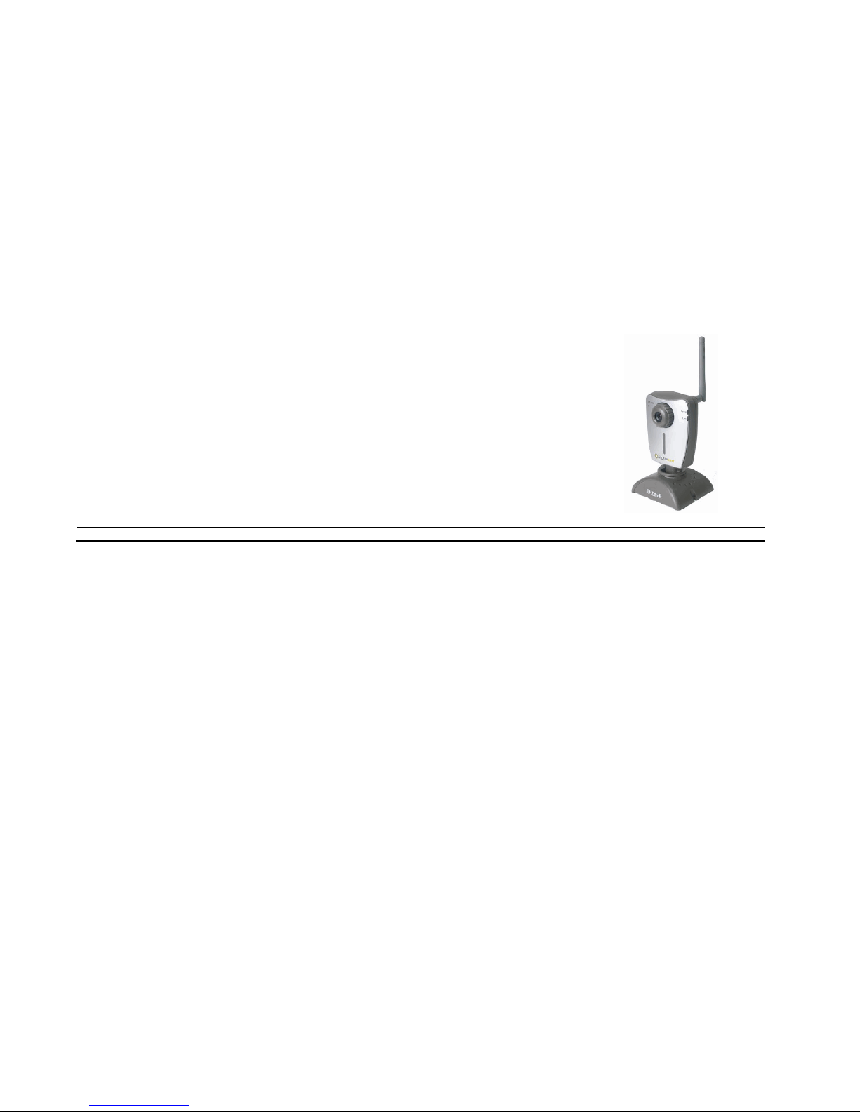
Congratulations on your purchase of the DCS-950G Internet Camera! The DCS-950G is a versatile and unique solution for your small office or home. Unlike a PC
Camera, the DCS-950G is a stand-alone system with a built-in CPU and Web server that transmit s high quality video images for monito ring. The DCS-950G can be
accessed remotely, and controlled from any PC/Notebook over the Intranet or Internet via a Web browser. The simple installation procedure and intuitive
web-based interface offer easy integration with your Ethernet/Fast Ethernet or 802.11g wireless network. The DCS-950G also comes with remote monitoring
capability for a complete and cost-effective home security solution.
Features and Benefits
Simple to Use: The DCS-950G is a stand-alone system with a built-in CPU, requiring no special hardware or software such as PC frame grabber cards. The
DCS-950G supports ActiveX mode for Internet Explorer. All that is required is a computer with Internet Explorer 6.0 or above.
Supports a Variety of Platforms: Supporting TCP/IP networking, HTTP, and other Internet related protocols. It can also be integrated easily into other
Internet/Intranet applications because of its standards-based features.
Remote Snapshot Images and Recording: Using the Snapshot and recording fe atures, you can save snapshot s and record video and audio directly from the Web
browser to a local hard drive without installing any software, making it convenient to instantly capture any moment from a remote location.
Record Directly to a NAS: The DCS-950G allows you to record directly to a local network area storage device without the use of a dedicated PC for storing
recorded video.
Low Light Recording: The DCS-950G’s 0.5 lux light sensitivity allows you to capture video in rooms with minimal lighting, making it ideal for use at night time.
802.11g Wireless or Ethernet/Fast Ethernet Support: The DCS-950G offers both 802.11g wireless and Ethernet/Fast Ethernet connectivity, making the
DCS-950G easy to integrate into your existing network environment. The DCS-950G works with a 10Mbps Ethernet based network or 100Mbps Fast Ethernet
based network for traditional wired environments and works with 802.11g routers or access points for added flexibility. The Site Survey feature also allows you to
view and connect to nearby wireless networks.
Web Configuration: Using a standard Web browser, Administrators can configure and manage the Internet Camera directly from its own Web page via the
Intranet or Internet. This means you can access your DCS-950G at anytime from anywhere in the world!
Remote Monitoring Utility: The IPView SE application adds enhanced features and functionality for the Internet Camera and allows administrators to configure
and access the Internet Camera from a remote site via Intranet or Internet. Other features include imag e monitoring, re cording images t o a hard drive, viewing up to
4 cameras on one screen, and taking snapshots.
Broad Range of Applications: With today’s high-speed Internet services, the Internet Camera can p rovide the ideal soluti on for live video images over the Intra net
and Internet for remote monitoring. The Internet Camera allows remote access from a Web browser for live image viewing and allows the administrator to manage
and control the Internet Camera at anytime, from anywhere in the world. Many applications exist, including industrial and public monitoring of homes, offices, banks,
hospitals, child-care centers, and amusement parks.
Page 7
3
Hardware Overview
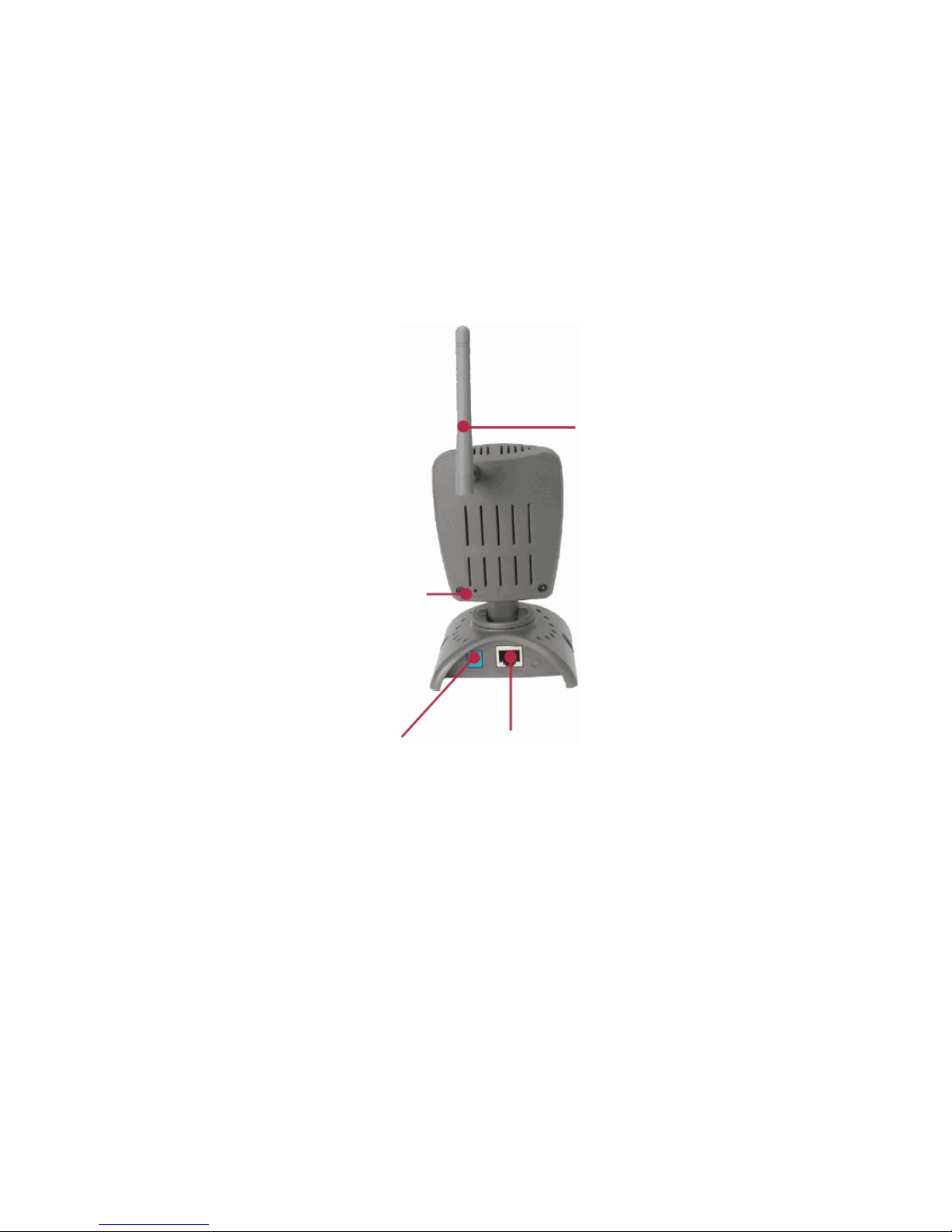
Connections
Reset Button
Reset will be initiated when the reset
button is pressed once and Power LED
begins to flash.
Factory Reset will be initiated when the
reset button is pressed continuously for
ten seconds. Release the reset button
and the Power LED will begin to flash
indicating that the DCS-950G’s settings
are reverting back to the factory settings.
The IP address will also return to the
default setting of 192.168.0.20.
802.11g Antenna
The DCS-950G features an
802.11g wireless antenna for
802.11g wireless connectivity to
your existing wireless network.
The DCS-950G can be used in
conjunction with an 802.11g
compliant access point or router.
Ethernet Cable Connector
The DCS-950G features an RJ-45 connector
for connections to 10Base-T Ethernet cabling
or 100Base-TX Fast Ethernet cabling (which
should be Category 5 UTP cable). The port
supports the NWay protocol, allowing the
DCS-950G to automatically detect or
negotiate the transmission speed of the
network.
The port also supports MDI/X, which
allows the use of either straight through or
crossover cables.
DC Power Connector
The DC power input connector is labeled DC
5V with a single jack socket to supply power
to the DCS-950G.
Page 8

4
LEDs
Power LED
The Power LED is positioned on the right side of the
DCS-950G lens. Steady orange confirms that the
DCS-950G is powered ON.
Link LED
The Link LED is positioned on the right side of the
DCS-950G’s lens. It is located below the Power LED.
Steady green confirms a good connection
to the LAN.
Depending on the data traffic, the LED will begin to flash
to indicate that the DCS-950G is receiving/transmitting
from/to the
LAN network.
Page 9

5
Hardware Installation
Attach the Antenna
Locate the antenna included with your DCS-950G and attach it to the antenna connector located on the back of the DCS-950G.
Attach the External Power Supply
Attach the external power supply to the DC power input connector located on the rear panel of the DCS-950G and connect it to your local power supply. Note:
Power source is confirmed when the orange LED Power Indicator located to the right of the lens on the DCS-950G is illuminated.
Connect the Ethernet Cable
Connect the included Ethernet cable to the network cable connector located on the back panel of the DCS-950G and attach it to the network. Network Connectivity
is confirmed when the green LED Indicator on the DCS-950G located below the Power LED is illuminated.
Page 10
6
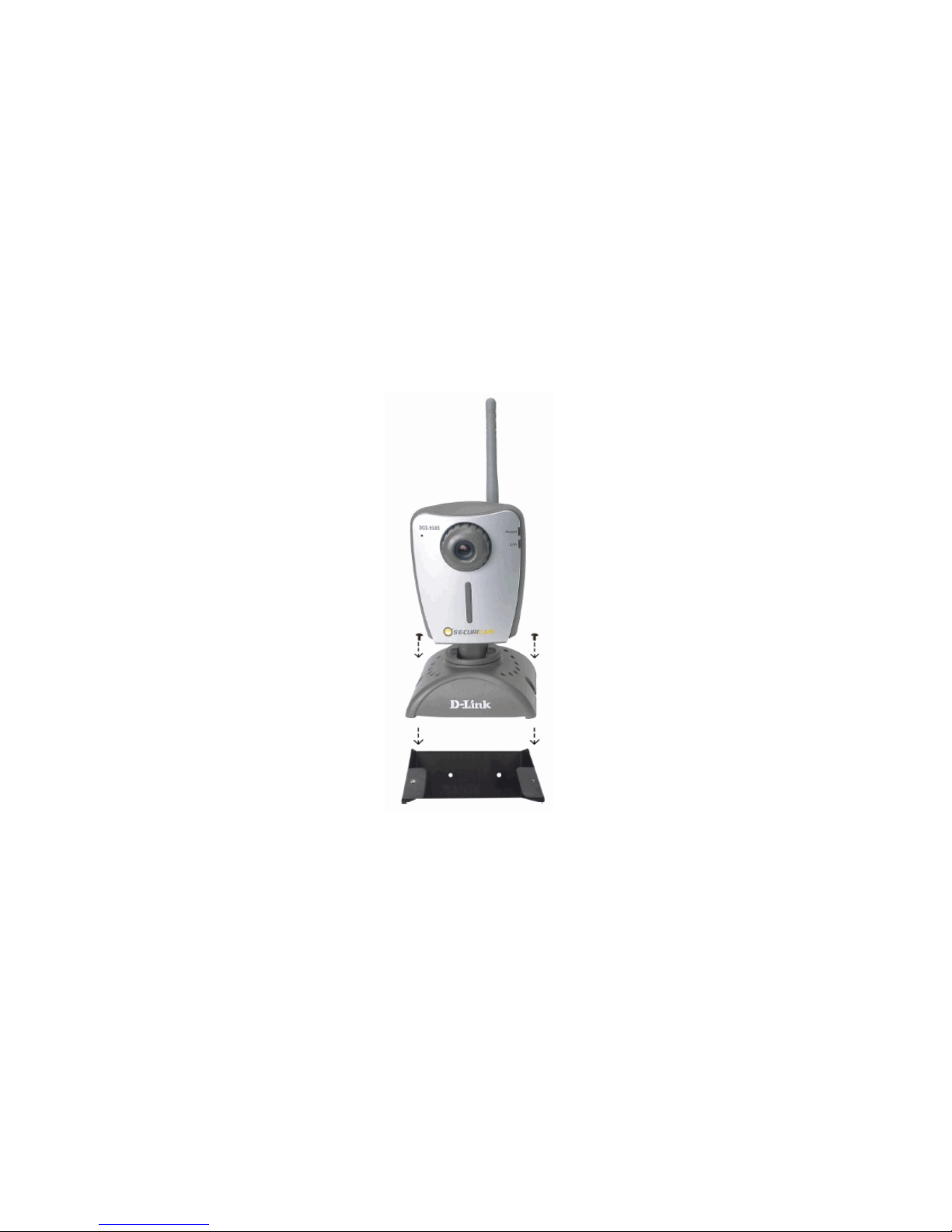
Attach the Mounting Bracket
If you would like to mount the camera on a wall, locate the necessary screws and continue with securing the bracket to the wall. To attach the mounting bracket to
the Camera, simply attach the Camera’s base to the bracket (see illustration below).
Page 11

7
Security
To ensure the highest security and prevent unauthorized usage of the DCS-950G, the Administrator has the exclusive privilege to authorize all users. The
DCS-950G supports multi-level password protection/access that can be restricted by the Administrator for defined users who have a User Name and User
Password.
The Administrator can release a public User Name and Password so that when remote users access the DCS-950G they will be allowed to view the images
transmitted by the DCS-950G.
NOTE:
When the DCS-950G is used for the first time, it is highly recommended that the Administrator set the Admin ID and Admin Password to constrain
user access to the DCS-950G since the Default settings for the Admin ID and Admin Password are both “admin.” Once the ID and Password are
defined, only the Administrator has access to the management of the DCS-950G. This procedure should be done as soon as possible.
Page 12
8
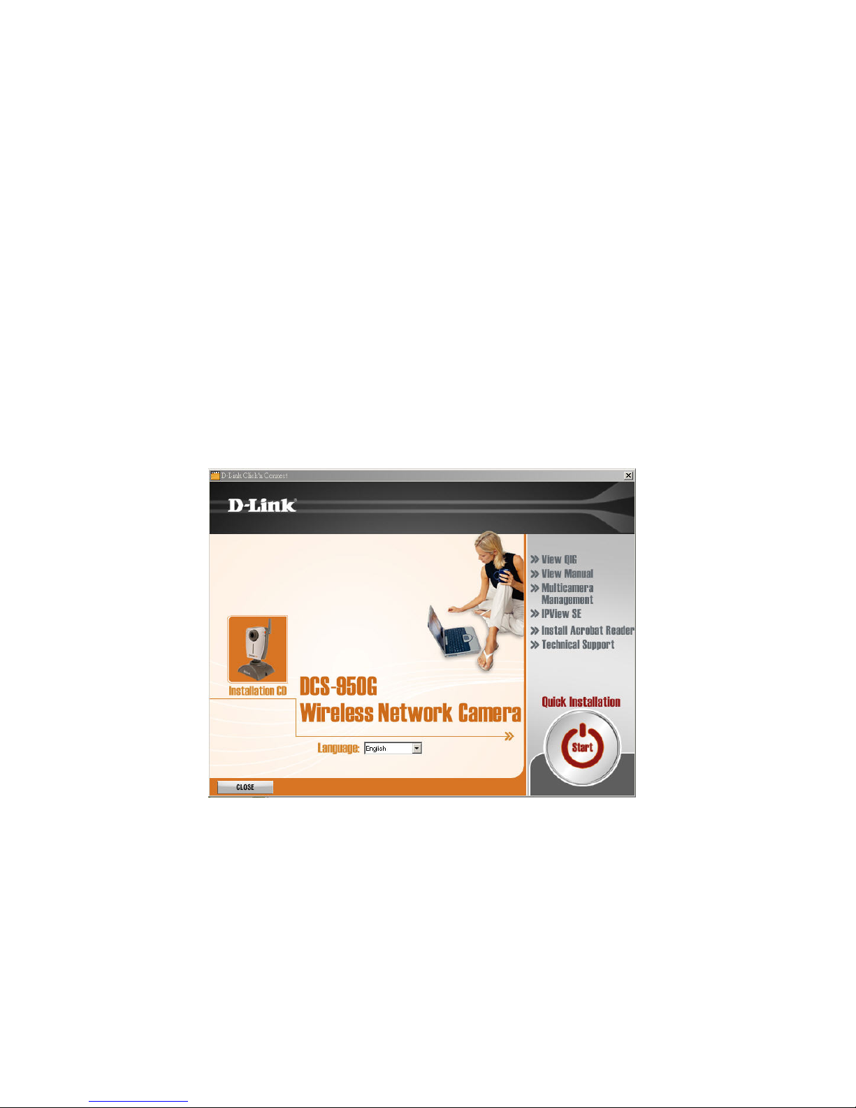
Auto-Run Installation
Insert the Installation CD-ROM into your computer’s CD-ROM drive to initiate the Auto-Run program. The content of the Installation CD-ROM includes:
• View Quick Installation Guide - click to preview the Quick Installation Guide in PDF format for step-by-step instructions of the DCS-9 50G Installation.
• View Manual – click to preview the User's Guide in PDF format for detailed information of the DCS-950G.
• Multicamera Management – click to install and use Setup Wizard to complete further settings for your Internet camera.
• IPView SE – click to install and use IPView SE to manage your cameras by enabling you to search, configure, and preview all the DCS-950Gs from one
location.
• Install Acrobat Reader – click to launch Acrobat Reader for the viewing and printing of PDF files in the Installation CD-ROM.
• Technical Support – Click to display the technical support information.
• Quick Installation – Click to start a quick installation.
• Exit – click to close the Auto-Run program.
Page 13
9
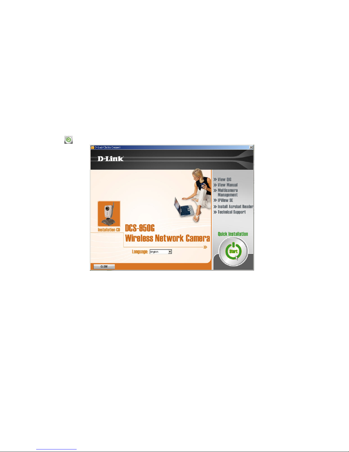
Quick Installation
Click the Start button to start the Quick Installation.
Page 14
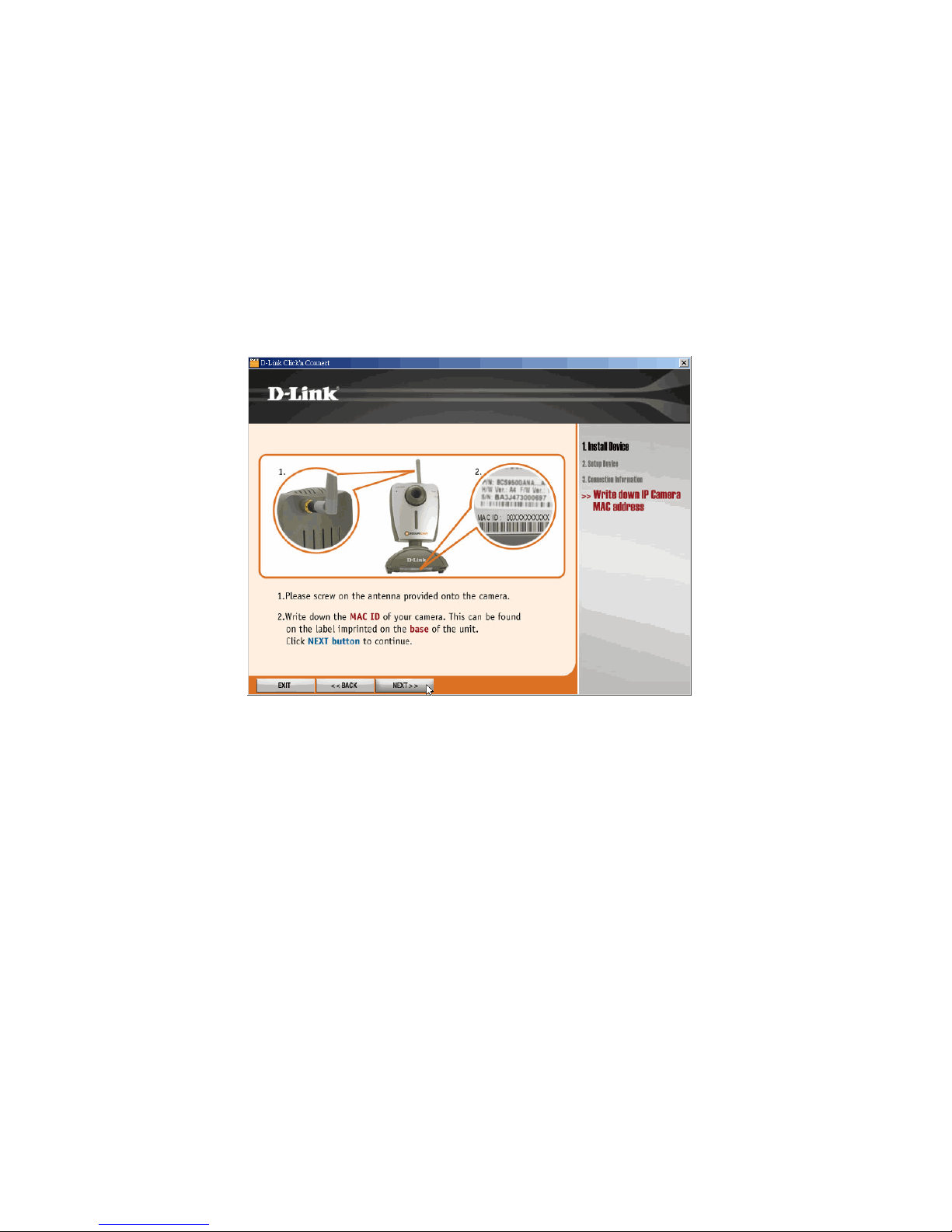
10
Follow the simple steps below to quickly install t he device, click NEXT>>.
Page 15
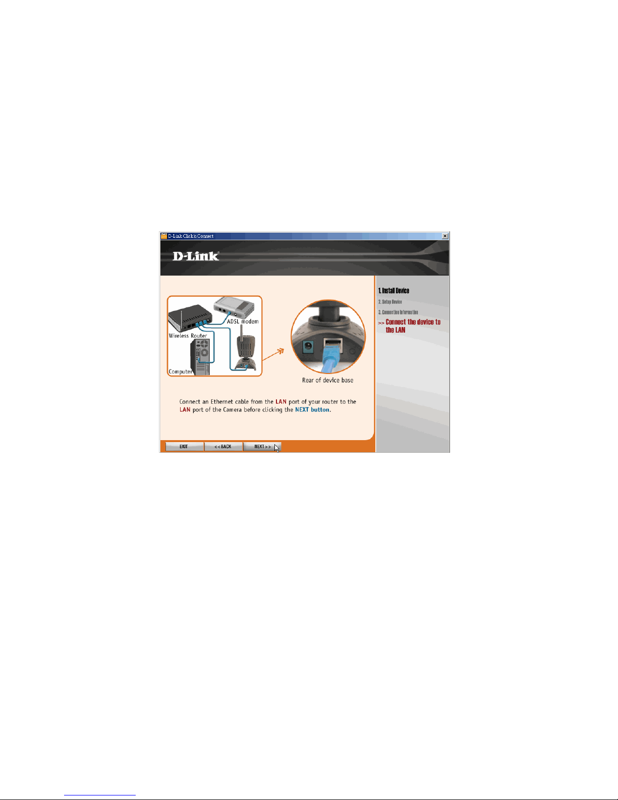
11
After done the connection of Ethernet cable, click NEXT>>.
Page 16
12
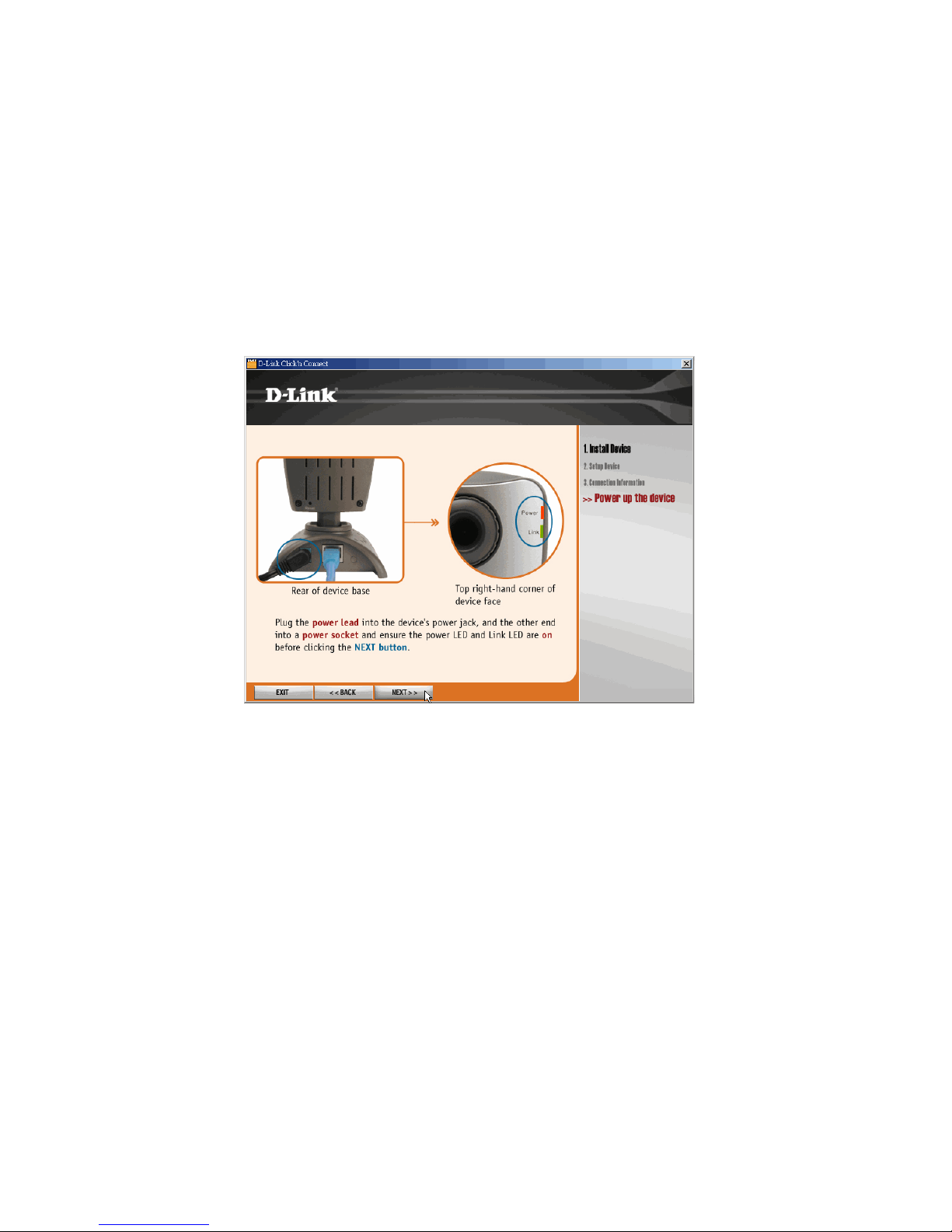
Follow the instruction below to power up the device, and then click NEXT>>.
Page 17

13
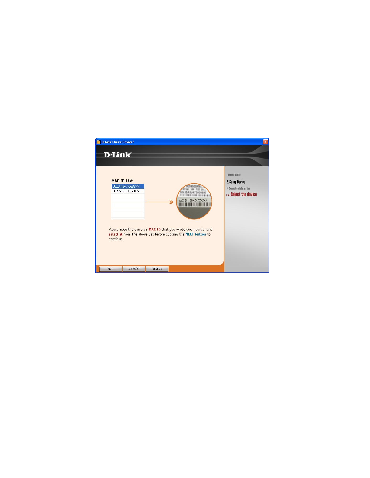
Then the system will automatically search the device.
Page 18
14
Select your camera’s MAC ID from the MAC ID List, and then click NEXT>>.
Page 19
15
DCC (D-Link Click’n Connect) will auto-detect whether your Internet connection with or without DHCP and diagnose that if DHCP is also available for your IP
camera or not in order to display the next corresponding screen.
With DHCP:
Since DHCP is available for your Internet connection and IP came ra, DCC will start DHCP assign automatically for your IP camera and display the following screen
when the process is done.
Page 20
16
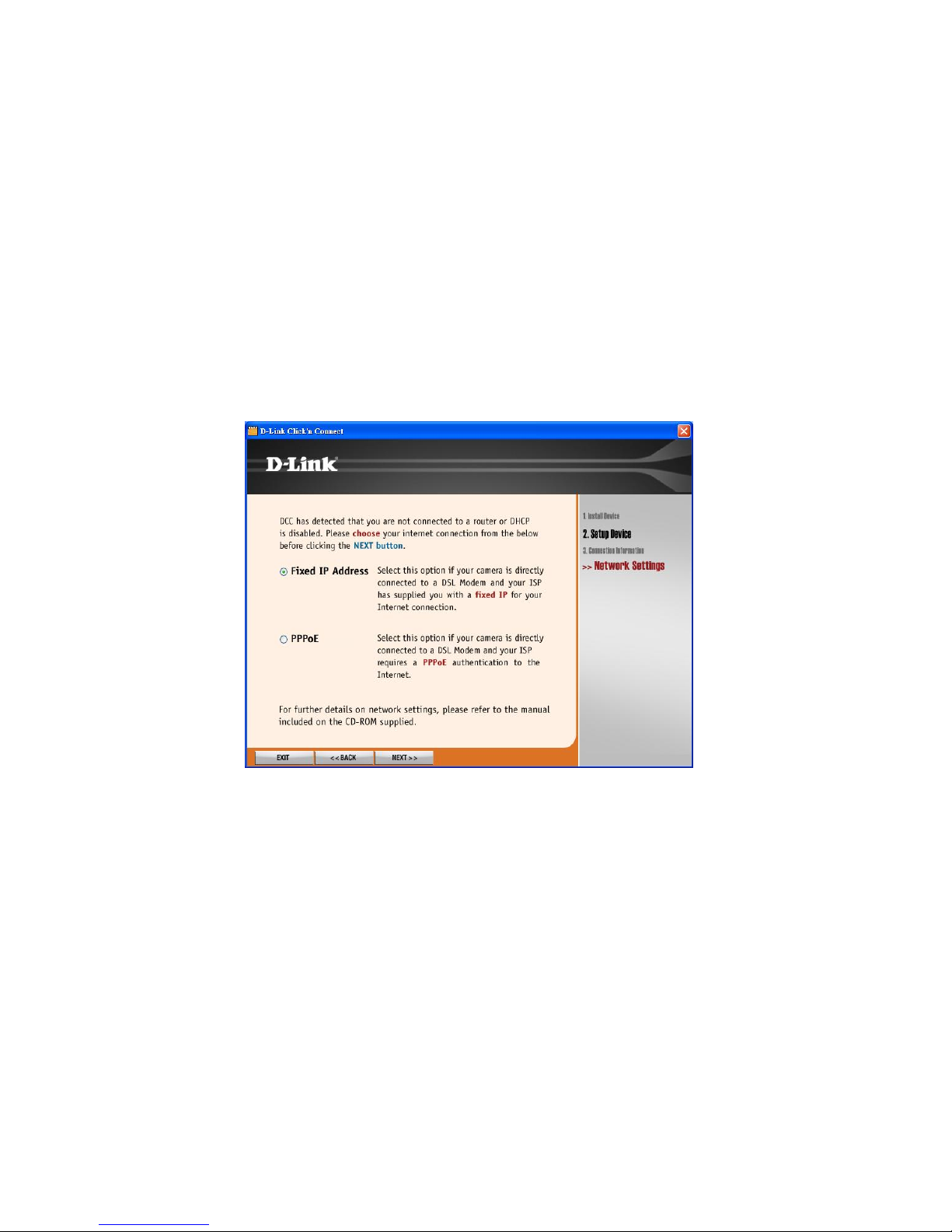
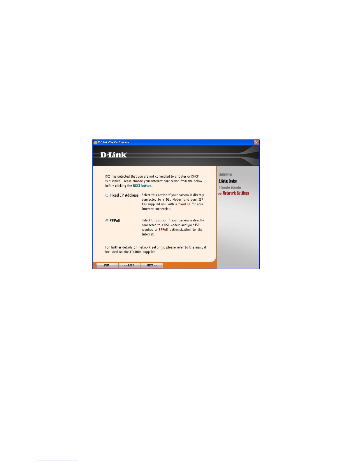
Without DHCP:
If DHCP is not available for your network and IP camera, the following screen will show up to allow you select Fixed IP Address or PPPoE for your Internet
connection.
For Fixed IP Address:
If your camera is directly connected to a DSL Modem and your ISP has supplied you with a fixed IP for your Internet conn ection, you may select this option and
click NEXT>> button to continue.
Page 21
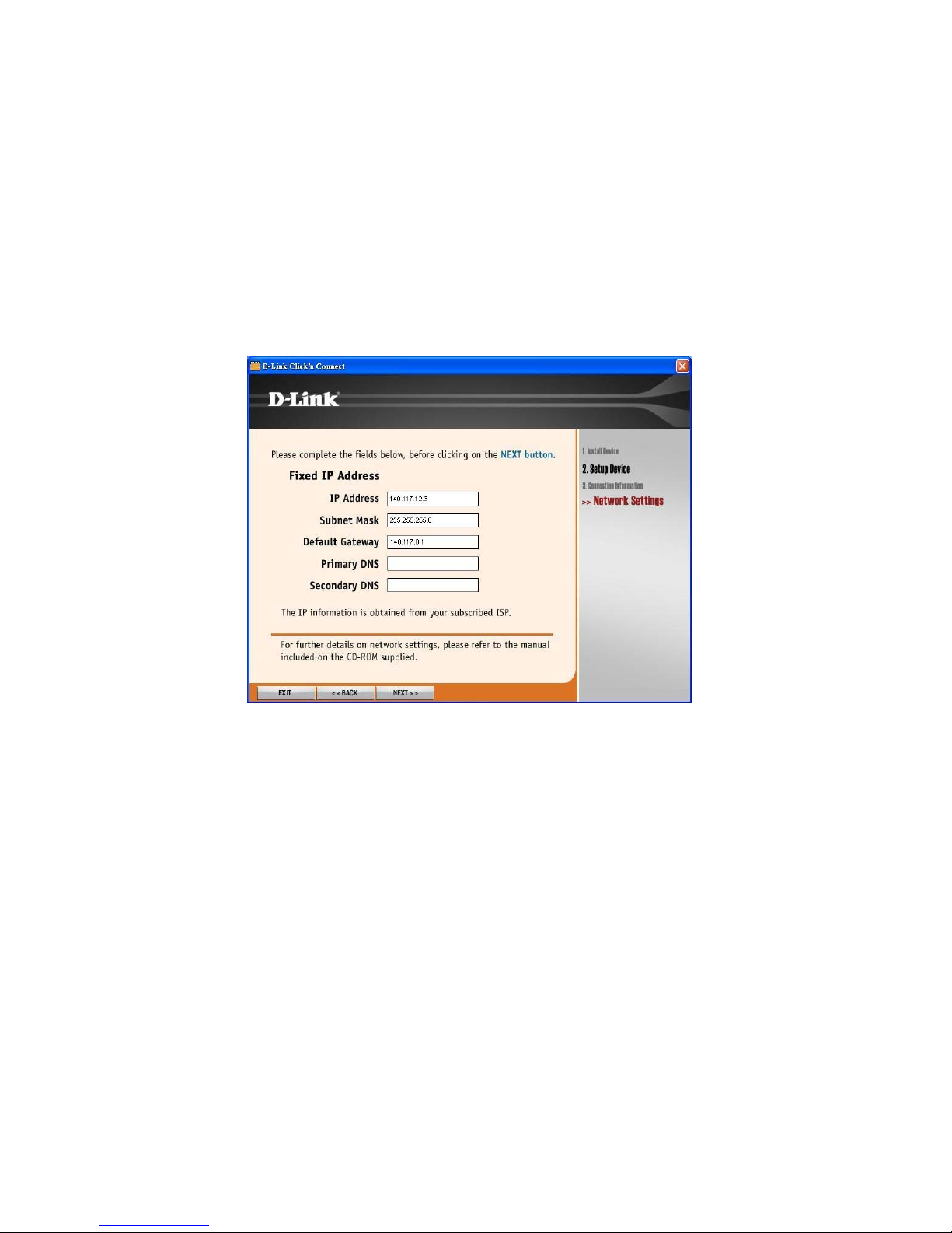
17
When Fixed IP Address is selected for your Internet connection, you nee d to fill the IP information in the related fields, and then click NEXT>>.
Page 22
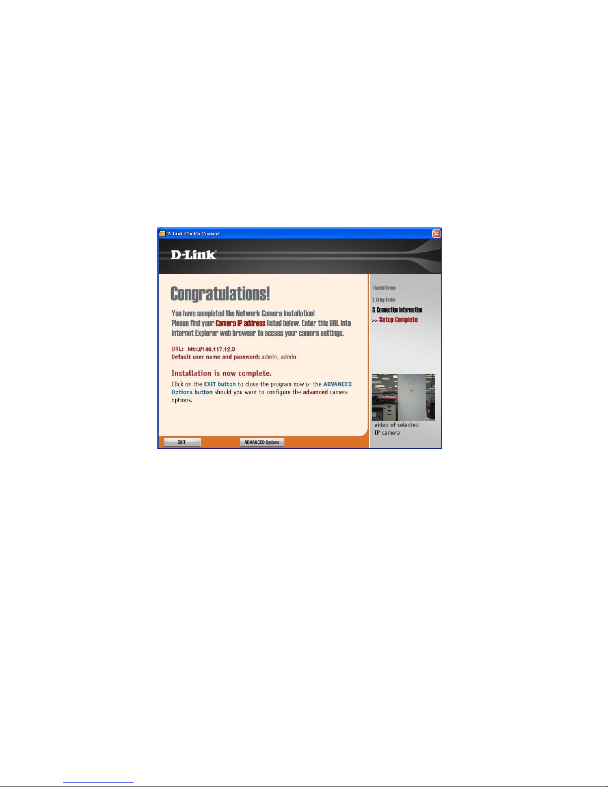
18
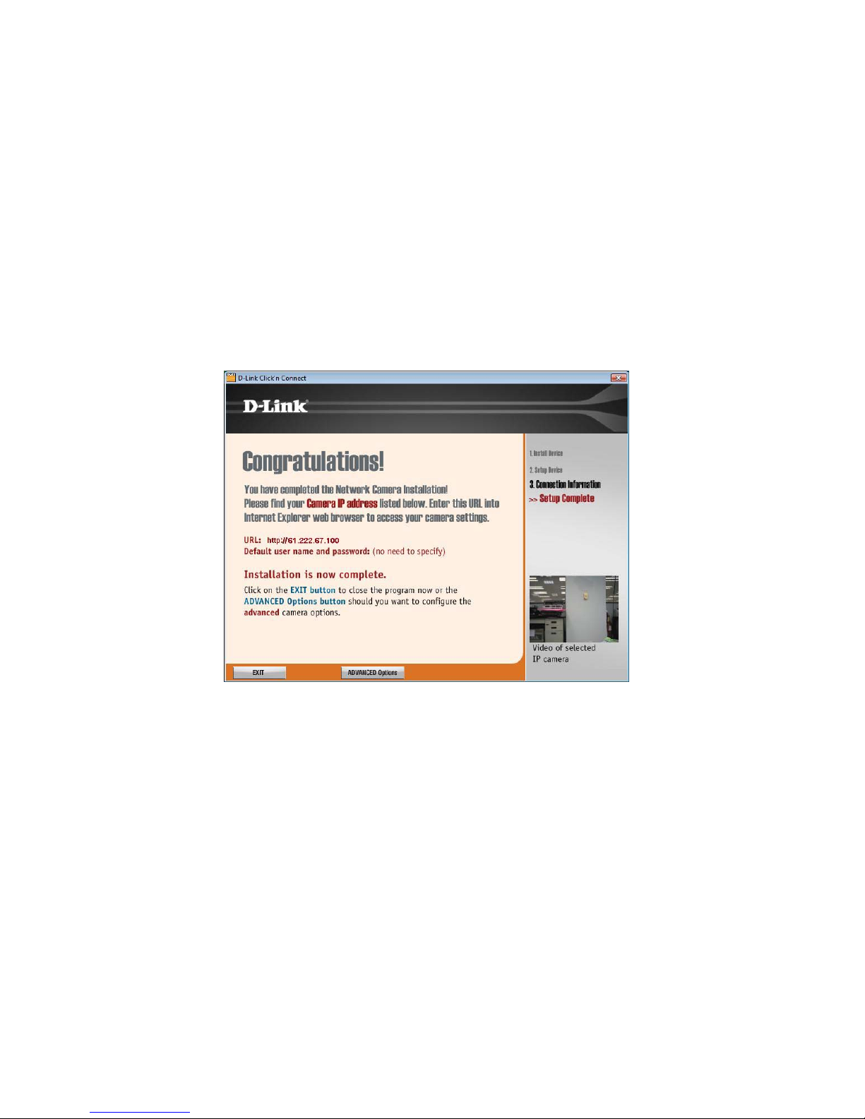
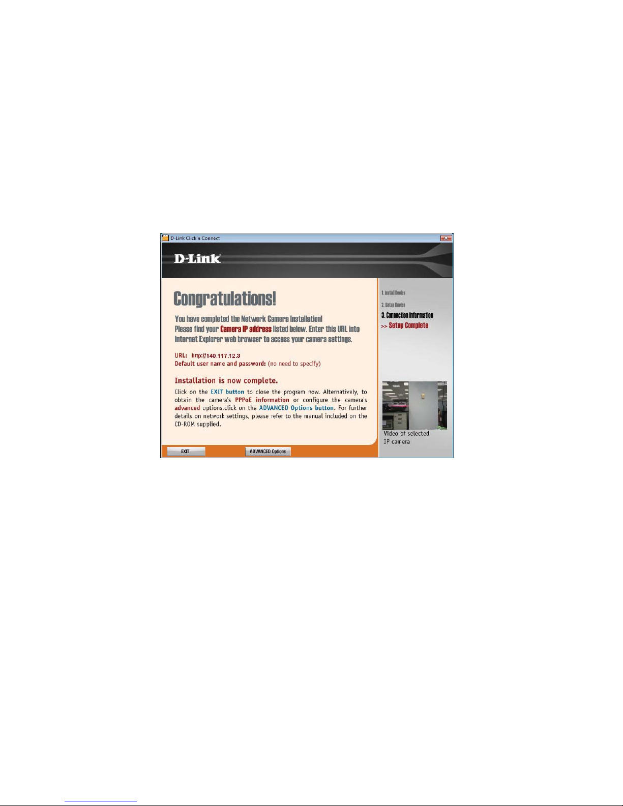
The installation is now complete. You may click ADVANCED Op tions to enter your IP camera’s Web Configuration or EXIT to leave the screen.
Page 23
19
For PPPoE:
Select PPPoE option and click NEXT>> button.
Page 24
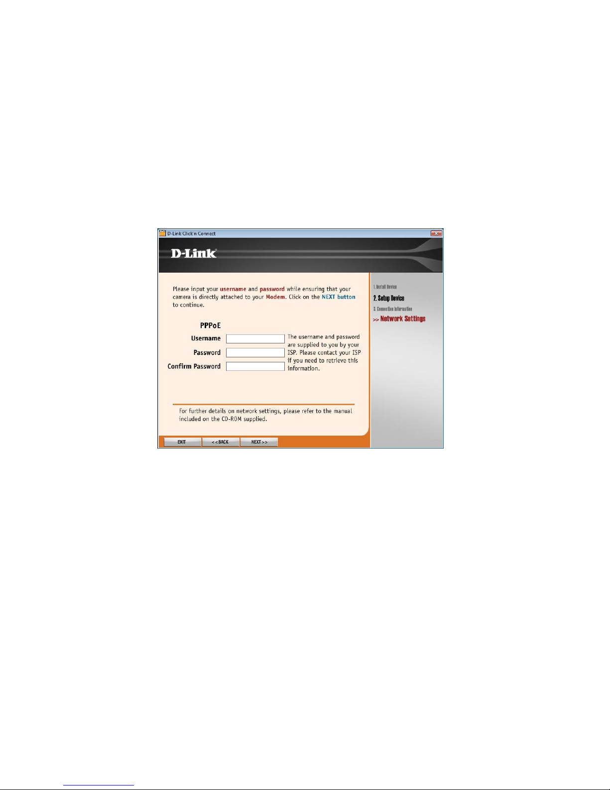
20
Enter Username and Password that are supplied by your ISP in the related fields and click NEXT>>.
Page 25
21
The installation is now complete. You may click ADVANCED Op tions to enter your IP camera’s Web Configuration or EXIT to leave the screen.
Page 26
22
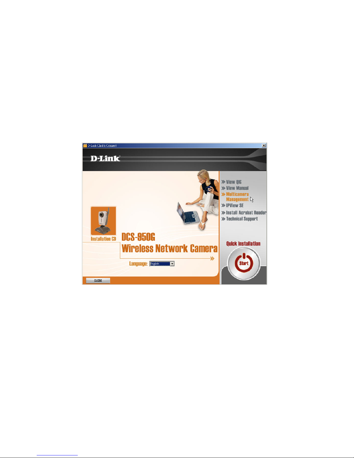
Multicamera Management
Click Multicamera Management of the Installation CD.
Page 27
23
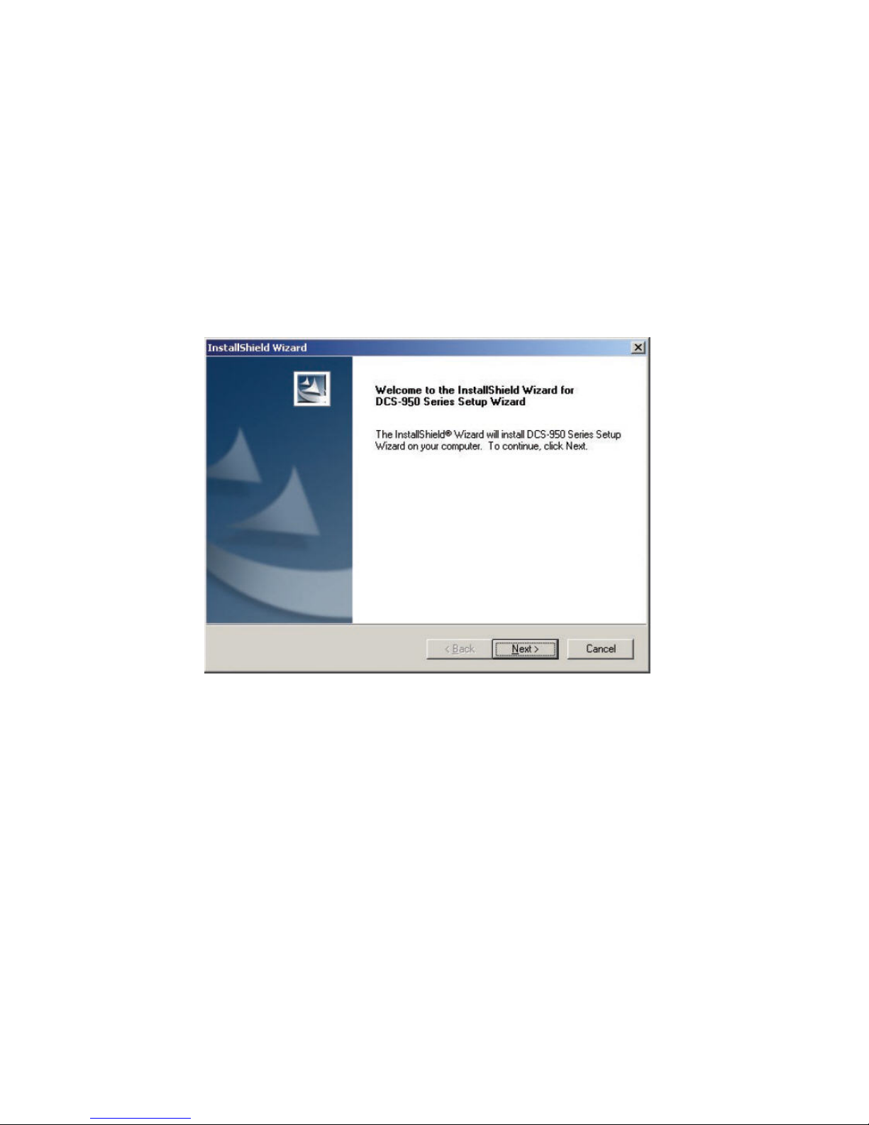
Follow the simple steps below to run the Setup Wizard to guide you quickly through the inst allation process.
Click Next.
Page 28
24
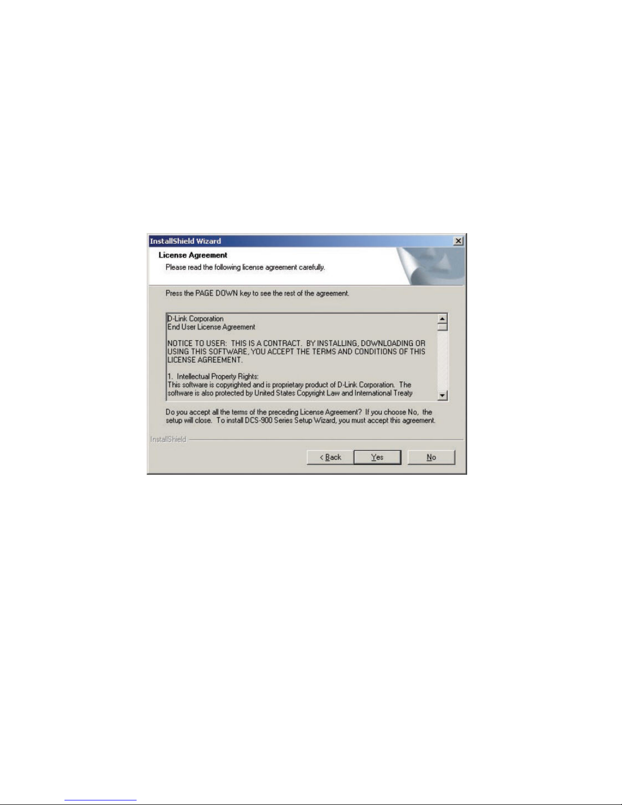
Click Yes.
Page 29
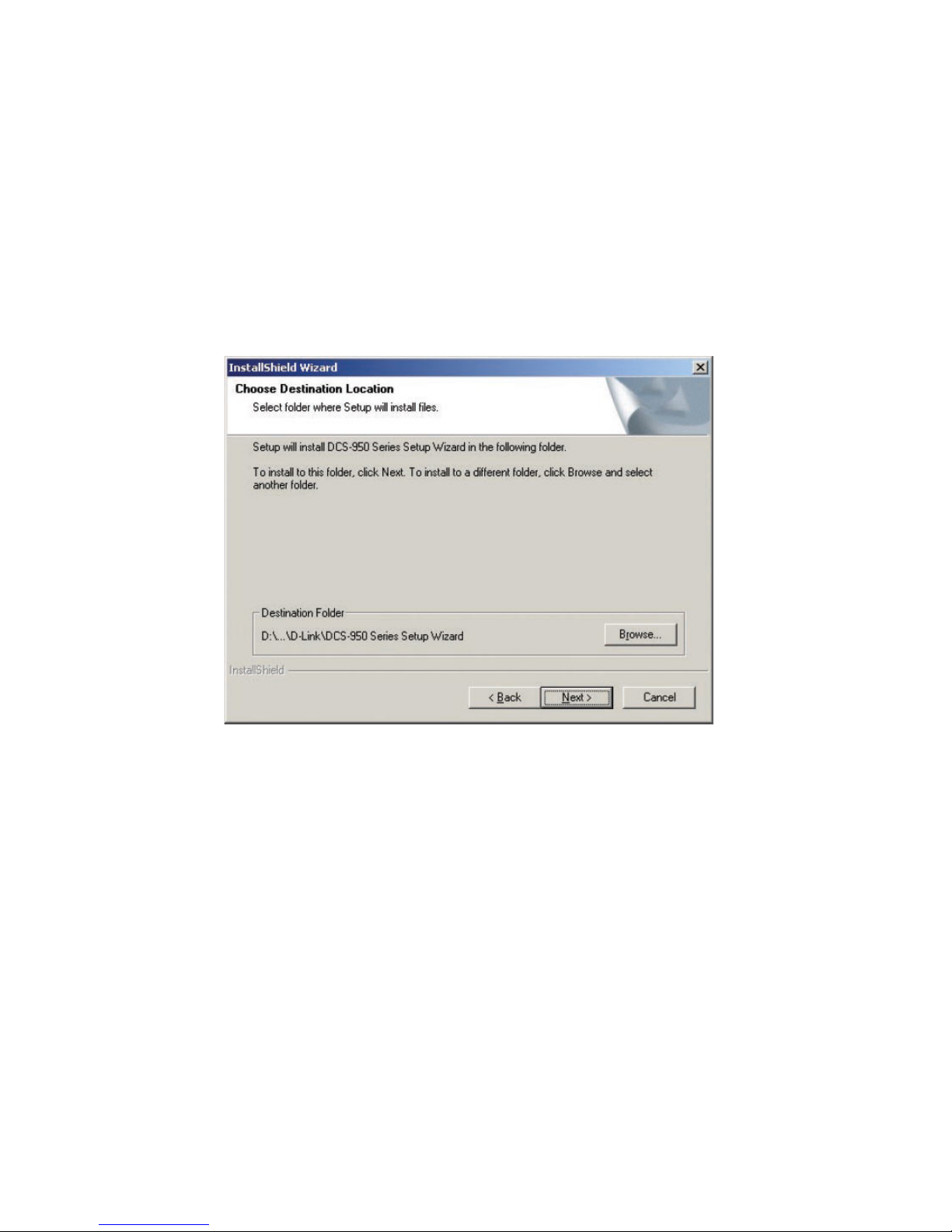
25
Click Next.
Page 30
26
Click Finish.
Page 31

27
Now you should install ffdshow, this will install the proper codec that will allow you to playback recorded video taken by the DCS-950G .
Select a language and click OK.
Page 32

28
Click Next.
Page 33

29
Click I Agree.
Page 34

30
Click Next.
Page 35

31
Click Install.
Page 36

32
Click Next.
Page 37

33
Click Finish.
Page 38

34
Before using ffdshow, you must configure its properties. From your computer, please click on StartÆ ProgramsÆ ffdshowÆ Configuration.
Page 39

35
At the ffdshow properties window, scroll to the bottom and click Miscellaneous. Be sure that Autodetect is checked and that Error resilience and Error
concealment are set to “none”. Click OK and close the window.
Page 40

36
Be aware that the Setup Wizard is offered for you to do configuration of your camera in the future only. Not necessary to run the Setup Wizard for your first time
using the camera.
To run the Setup Wizard, click on StartÆ ProgramsÆ DCS-950 Series Setup Wizard. Your camera’s default IP Address will be displayed on the screen. Click
Wizard to begin.
Page 41

37
By default, the Admin ID and Password are “admin” (lower case). Enter this in both fields. To change the Admin Password, select the Change box and enter a New
Password. Click Next.
Page 42

38
The IP Address, Subnet Mask of your camera, Gateway, and DNS addresses must correspond with your network settings for you to access the camera. If you are
unsure of what these settings should be, please check with your network administrator. Click Next.
Page 43

39
The Connection Mode depends on how your camera is connected to your network. Click Infrastructure for use with a router or Adhoc for a peer-to-peer connection.
The Network Name, Wireless Channel, Security Mode, and Authentication type MUST corre spond with your wi rel ess n etwork settin gs for the ca mera to work. Click
Next.
Page 44

40
Enter the Encryption Mode, Key Format, and Encryption Keys for your wireless network. Click Next.
Page 45

41
If you need to make any changes, click Back to modify your camera settings. Otherwise, click Restart to save and apply your settings. This may take a few minutes
Page 46

42
Y our setup is now complete! Wait until the Link LED on the camera begins to flash. Click Link to launch your Web browser and view your images.
Page 47

43
After you click the Link button, the Installation Wizard will automatically open your Web browser to the IP address of the DCS-950G and prompt you for a user
name and password. Enter “admin” into both fields. If you changed the user name and password in the setup wizard, enter the new values and click Log In.
Page 48

44
After you successfully log in, the camera will be displayed in your Web browser.
Page 49

45
Using the Configuration Menu
After completing the Setup Wizard, you are ready to use your camera. The Web configuration utility is designed to easily access and configure your DCS-950G.
Click the “Link” button will open up the main configuration page.
If you would like to open the configuration page from a Web Browser, enter the IP address that you assigned to your DCS-950G. In this example the IP address of
the camera is http://192.168.0.20. Your DCS-950G may have a different IP Address. Then the system will request you to enter user name and password (Both
default user name and password are admin) to login in.
After login in the Web Configuration menu, the home screen will show up. Use the following displayed sections to set up and view your Internet Camera:
LIVE VIDEO
SETUP
MAINTENANCE
STATUS
HELP
Page 50

46
LIVE VIDEO
This section allows you to set up your IP camera's live video by using the buttons below.
LIVE VIDEO > Camera
Audio – To receive voice from the area surro undi ng your DCS-950G, click this button to turn on the built-in microphone on your DCS-950G. The audio is on
by default.
Snapshot – Click it to capture a snapshot image. The image will pop up in a new window. Then you may save this image to a local hard drive.
Night Shot – Click this button if your IP camera is operating under low light condition. In this setting the DCS-950G will be able to view at 0.5 Lux.
Client Recording – Click this button will start recording video immediately to the file path specified in the right field.
Stop Client Recording – To stop recording video immediately, click this button.
Page 51

47
Page 52

48
SETUP
This section allows you to further set up or change the configuration of your IP camera.
SETUP > Network Setup
This option, Network Setup, allows you to configure your LAN and Internet configuration, including the settings for LAN, PPPoE, and port. After done the
configuration, you may click Save Settings button to save the new settings or Don’t Save Settings button to abandon it.
Page 53

49
LAN Settings – If you are using a LAN connection, select either DHCP Conne ction or Static IP Address. If manually assigning a Static IP, enter your IP Address, IP
Subnet Mask, Gateway IP Addre s s, and DNS into the fields provided.
PPPoE Settings – If you are using a PPPoE connection, enable it and enter the User Name and Password for your PPPoE account.
Port Settings –
y Web Port: This is the port that allows the user to connect to the camera’s user interface. By default the port is set to 80. You may change the port number if
using multiple cameras.
NOTE:
Y ou MUST also set up your router/gateway for Port Mapping; this will enable remote viewing of your camera via the Internet. Please refer to your
router’s instruction manual on how to open up ports. For additional help on configuring your camera to work with your router, please refer to the next
section on setting up your camera for use with a router. For installing multiple cameras, ONE port per camera must be opened on your router, the
Web server (HTTP) port.
y AV Control Port: This is the port that allows the user to connect to synchronize your IP camera’s audio and video. By default the port is set to 5000. You may
change the port number if using multiple cameras.
y AV Streaming Port: This is the port used to stream video. By default the port is set to 5001. You may change the port number if using multiple cameras.
Page 54

50
SETUP > Wireless
To set up your IP camera's wireless network interface settings, enable Wireless Settings in this window first. Then continue the further configuration next. After
done the configuration, you may click Save Settings button to save the new settings or Don’t Save Settings button to abandon it.
Page 55

51
Basic Wireless Settings –
y SSID: Short for Service Set Identifier, a name that identifies a wireless network. Access Points and wireless clients attempting to connect to a specific WLAN
(Wireless Local Area Network) must use the same SSID. The default setting is NULL. Changing your SSID is the first step in securing your wireless network.
We recommend that you change it to a familiar name that does not contain any personal information.
y Channel: It allows you to select a wireless channel that is the same as the other wireless devices on your network. You are recommended to choose Auto (Auto
Channel Scan) so that the camera can select the best possible channel for your wireless network to operate on.
y Connection Mode: Two options are available for yo u to select:
- Infrastructure
– connecting the WLAN using an Access Point such as the DWL-2100AP or a DIR-300 wireless router. (The default setting.)
- Ad-Hoc
– wireless mode used when connecting directly to a computer equipped with a wireless adapter in a peer-to-peer environment.
y Site survey – this button allows you to scan your environment for available wireless networks.
Wireless Security Mode – Select between None, WEP, or WPA_PSK.
y None: Select it means no encryption will be set on your IP camera.
y WEP: Short for Wired Equivalent Privacy. You may select it to set encryption from 64 to 128 bits.
y WPA_PSK: If the security mode is set to WPA-PSK (Wi-Fi Protected Access with pre-shared key), you must set up the following WPA-PSK Settings section.
WPA-PSK Settings –
y Key Format: Two formats are available for you to select: HEX or ASCII.
y Pre-Shared Key: you must specify a pre-shared key in this field. For HEX format, input 64 printable Hex characters; For ASCII, input 8 to 63 printable Hex
characters.
NOTE:
If encryption is enabled on the router or access point on your network, your IP camera must share the same encryption key to access the device.
Page 56

52
SETUP > Dynamic DNS
If you have a DSL or Cable service provider that changes your modem IP address periodically, Dynamic DNS (Domain Name Service), a method of keeping a
domain name linked to a dynamic IP address, is useful. With most Cable and DSL connections, you are assigned a dynamic IP address and that address is used
only for the duration of that specific connection. With the DCS-950G, you can set up your DDNS service and the DCS-950G will automatically update your DDNS
server every time it receives a different IP address. Depending on the service, this update may take a few hours.
If you are using a DDNS connection, select Enable option and enter in your Host Name, User Name, and Password. After done the configuration, you may click
Save Settings button to save the new settings or
Don’t Save Settings button to abandon it.
Page 57

53
SETUP > Image Setup
This option, Image Setup, allows you to adjust the settings for your IP camera sensor and image. After done the configuration, you may click Save Settings button
to save the new settings or Don’t Save Settings button to abandon it. Note that if parameters are changed without saving, they will be effective until the next system
power up.
Page 58

54
Image Settings –
y Enable Anti Flicker: This option adjust the camera sensor’s setting to avoid the image flickering issue under certain light sources. Only use this option when it
is necessary.
y Flip Image: This will flip the image vertically. This feature can be used if you choose to mount the DCS-950G upside down on the ceiling.
y Mirror: This will flip the image horizontally in such a way that your left side will be on the left side of the screen and vice versa.
y Brightness: There are eleven levels ranged from -5 to +5 for less brightness and more brightness. After selecting your setting, please wait a few seconds for
the camera to adjust accordingly.
Page 59

55
SETUP > Audio and Video
This Audio and Video option allows you to set up your IP camera’s video quality, resolution, and Frame rate. After done the configuration, you may click Save
Settings button to save the new settings or
Don’t Save Settings button to abandon it.
Video Settings –
y Default: For the default level, you may configure the viewing video quality and the size of the video display:
- Quality – Four options are available for this parameter: High (default), Middle, Low, and Very Low.
Page 60

56
- Capture Resolution – Three options are available for this parameter: VGA (640x480), QVGA (320x240), QQVGA (160x120). By default the capture
resolution is set to VGA (640x480).
y Custom: For the custom level, you are allowed to configure Capture Resolution, Frame Rate, and Bit Rate:
- Capture Resolution – Three options are available for this parameter: VGA (640x480), QVGA (320x240), QQVGA (160x120). By default the capture
resolution is set to VGA (640x480).
- Frame Rate (fps) – Three options are available for the refresh frame rate: 5, 7, 10, 15, and 30. By default the frame rate is set to 15 frames per second
(fps).
- Bit Rate – The higher the bit-rate the better the picture quality, while at the same time the file size will also be larger.
NOTE:
Higher frame size, frame rate and bit rate gives better video quality. At the same time, it requires more network bandwidth. For Best viewing result
on a mobile phone, we suggest setting the Frame Rate to 5 fps and Bit Rate to 20 kbps.
Audio Settings – Only ADPCM is supported for your IP camera.
Light Frequency – This allows you to improve image by selecting the related parameters: 50 Hz or 60 Hz.
Page 61

57
SETUP > Mail
This option allows you to configure mail settings. If you want to specify the IP camera email settings, you may check By E-mail checkbox and modify the further
related settings on the Mail Settings section. If you are setting up motion detection and will not be recording onto a PC, you can setup an FTP or SMTP account in
the camera. You will be emailed or sent images when motion is detected. After done the configuration, you may click
Save Settings button to save the new settings or Don’t Save Settings button to abandon it.
Mail Settings –
y Login Method: You may chose Anonymous or Account. If Account is adopted, entering user name and password to login your e-mail account is necessary.
y SMTP (mail) Server: The domain name or IP address of external mail server.
y Return Email Address: The return e-mail address to use if the snapshot or system log e-mail fails to send. (This address should be within the SMTP server’s
domain for authentication purposes.)
Page 62

58
y Recipient Email Address: The e-mail address of recipients for snapshots or a system log file.
y Port: This is a port number for your SMTP server. The default setting is 25. If you use ports other than 25 you can change it here.
Motion Detection –
y Motion Detection Skip Time: Increasing the time set here will avoid false alarms. This option allows you to set the amount of time between motion detection
events before the next recording will start.
SETUP > Motion Detection
This option allows you to set up Motion Detection on your IP camera. In order to use motion detection you must first check the Enable Motion Detection checkbox. A
maximum of 3 windows can be created each with their own separate Sensitivity and Percentage ranges. After done the configuration, you may click
Save Settings button to save the new settings or Don’t Save Settings button to abandon it.
Page 63

59
Page 64

60
y Percentage: Increasing the time set here will avoid false alarms. This option allows you to set the amount of time between motion detection events before the
next recording will start.
y Sensitivity: Sets the measurable difference between two sequential images that would indicate motion.
y Zone 1-3: Click to open the corresponding motion window. To assign a name to the window, enter the desired name in the entry field next to the zone button.
y Save: Saves the related settings of that window.
y Open Motion Status Dialog: Click to open the Motion Screen Display. The small window allows you to monitor the amount of motion detected in each motion
window. The graphic b ars will increase or decrease depending on the image variation. A blue bar means the image variation is under the monitoring level, and
no motion detection alert is triggered. A red bar means the image variation is over the monitoring level and a motion detected alert is triggered.
Page 65

61
SETUP > Time and Date
This option allows you to configure, update, and maintain the correct time on the internal system clock. From this section you can set the time zone that you are in
and set the NTP (Network Time Protocol) Server. Daylight Saving can also be configured to automatically adjust the time when needed. After done t he configuration,
you may click Save Settings button to save the new settings or Don’t Save Settings button to abandon it.
Page 66

62
Time Configuration –
y Current Server Time: The system will display the current server date and time here.
y Time Zone: Several options in the pull-down menu for you to select in order to adjust the hour of time servers for local settings.
y Enable Daylight Saving: If you want to enable Daylight Saving feature, check this checkbox, then the related parameters will be available for you to do the
further settings next.
y Daylight Saving Offset: Used to adjust correction to account for DST (Daylight Saving Time) if applicable in your region.
y Daylight Saving Date: Used to adjust the range of time and date for DST if applicable in your region.
The system of your IP camera provides you two methods of time configuration: Automatic or Manual:
Automatic Time Configuration – To adopt this feature, check the Synchronize NTP Server checkbox first, and then ent er the IP address or domain name of the
time server. Leaving the box blank will connect the camera to default time servers.
Set The Date and Time Manually – Manually set the time by selecting the Year, Month, Day, Hour, Minute, and Second. Otherwise, you may
synchronize the date
and time of the camera with the local computer.
Page 67

63
SETUP > Schedule
This option allows you to configure he recording settings and schedule as well as enable uploading image to network share fold er. After done the configuration, you
may click Save Settings button to save the new settings or Don’t Save Settings button to abandon it.
Page 68

64
Record Setting – Check the Enable checkbox to enable this feature in order to continue the further settings.
Record Detail Setting –
y Login Method: Select either Anonymous or Account. By selecting Anonymous, no user name or password is required. If you select Account from the drop
down menu, you will need to know the Username and Password to access the shared folder.
y Path: Enter the path that points to the shared folder e.g. \\DNS-G121\share.
Audio – Allow you to enable or disable it.
Shared Folder Mode –
y None: Used to disable the shared folder mode.
y Recording File Number: Used to specify the numbers of recording file. The default is 24.
y Total File Size: Used to specify the total file size for the shared folder. The default is 1000 MB.
Recording Method –
y Always: Allows you to record all the time.
y Schedule: Allows you to record based on a specific time and date; therefore, you must specify the time and date on Schedule Advanced section.
y Smart Recording: Allows you to only save files in which movement is detected, then you need to specify the save time in MD section.
Page 69

65
Page 70

66
SETUP > URL JPG
This option allows you to configure the name of URL to be used to request JPG image. You can access jpg by using the URL JPG name in your web bro w ser. For
example: By default you can enter http://ip/iMode.asp
After done the configuration, you may click Save Settings button to save the new settings or
Don’t Save Settings button to abandon it.
Page 71

67
MAINTENANCE
MAINTENANCE > Device Management
To ensure the highest security and prevent unauthorized usage of your IP camera, the Administrator has the exclusive privilege to authorize all users. The
DCS-950G supports multi-level password protection/access that can be restricted by the Administrator for defined users who have a User Name and User
Password.
The Administrator can release a public User Name and Password so that when remote users access the DCS-950G they will be allowed to view the images
transmitted by the DCS-950G.
Note that when the DCS-950G is used for the first time, it is highly recommended that the Administrator set the Admin ID and Admin Password to constrain user
access to the DCS-950G since the Default settings for the Admin ID and Admin Password are both “admin.” The password must be at least 5 characters. Once the
ID and Password are defined, only the Administrator has access to the management of the DCS-950G. This procedure should be done as soon as possible. After
done the configuration, you may click Apply button to save the new settings.
Page 72

68
Page 73

69
MAINTENANCE > Backup and Restore
The Backup and Restore option not only allows you to save the current configuration in a computer for backup by clicking Save Configuration button, but also
allows you to reload a configuration that you saved before by clicking Browse to direct to the backup file, and then clicking Restore Configuration From File button
for reloading with rebooting the device. Beside, you are also allowed to return your IP camera to the default settings by clicking Restore Factory Defaults button,
and restart the camera by setting the Ad ministrator timeout.
Page 74

70
MAINTENANCE > Firmware Update
The Firmware Update option displays you the current firmware’s information of your IP camera, and also allows you to upgrade the firmware of the IP camera
when a new version of firmware is available.
First, check the D-Link support site for firmware updates at http://support.dlink.com. Make sure that the firmware you want to use is saved on the local hard drive of
your computer. Click on Browse to search the local hard drive for the firmware that you downloaded from the D-Link Website to be used for the update. Upgrading
the firmware will not change any of your system settings but it is recommended that you save your system settings before doing a firmware upgrade.
Page 75

71
STATUS
The Status section provides the det ail information about your IP camera.
STATUS> Device Info
The Device Info option lists the following important settings that are currently set for your DCS-950G, including information for LAN setting, Image setting, wireless
LAN, PPPoE status, camera name, and firmware version.
Page 76

72
HELP
The Help screen provides you brief information about the DCS-950G for your reference.
Page 77

73
Installing the DCS-950G Behind a Router
Single Camera Installation
If you are installing a single camera on your network the inst allation is an easy 4–step procedure:
1) Identify Your Camera on the Network
2) Assign a Local IP Address for Your Camera
3) Determine Your Router’s WAN IP Address (Enable Remote Viewing)
4) Open Virtual Server Ports for Your Router (Enable Remote Viewing)
Multiple Camera Installation
If you are installing multiple cameras on your network, the installation is an easy 5-step procedure:
1) Identify Your Camera on the Network
2) Assign a Local IP Address for Your Camera
3) Open a Second Port on the Camera
4) Determine Your Router’s WAN IP Address (Enable Remote Viewing)
5) Open Virtual Server Ports for Your Router (Enable Remote Viewing)
Page 78

74
1) Identify Your Camera on the Network
Once you are logged into the camera via a Web browser on your network PC, click on MAINTENANCE, and select Dev ice Management. Enter a unique Camera
Name. These settings are important if you are installing several cameras on your network.
Page 79

75
2) Assign a Local IP Address for Your Camera
A Local IP Address is required to configure your camera and to view your camera within your local (home) network. You may use the default camera IP Address of
192.168.0.20. If you wish to use a different IP Address, be sure that the camera settings correspond to your network settings. The Default Gateway will be the IP
Address of your router’s Local IP Address (e.g.192.168.0.1, if you are using a D-Link router)
Page 80

76
Assigning and Opening the HTTP Port on the DCS-950G
(For Installing Multiple Cameras)
Opening ports will allow users to view the camera via the Internet. The ports that are opened must be unique for each camera in order to successfully view the
images remotely.
3) Open the HTTP Port
The HTTP Port option is used when multiple cameras are being installed behind a single publi c IP address and will be accessed remotely OR for using a port other
than the default port for image viewing. For each additional camera that is installed, you must assign the appropriate Web server port for each camera to enable
remote viewing.
By default, port 80 (Web server port) is open. If these ports are available for use, you DO NOT have to open a second port and can proceed to the next section. If
port 80 is not available (for example, if you are already using port 80 to run a Web server or your ISP blocks access on po rt 80*) yo u MU ST open a secon d port and
designate a new Web server port (800, 801, 802, etc.) and new AV Control and Streaming ports (5002, 5003, etc.). IMPORTANT: Be sure to take note of these
settings since these same settings will be used to configure your router.
NOTE:
Some ISPs block traffic on commonly used ports like port 80 to disallow consumers from putting a server on their network. Be sure to check with your
ISP so that you can open the appropriate ports accordingly. If your ISP does not pass traffic on port 80, you will need to change the Web server port the
camera uses from 80 to something else, like 800. If you are behind a residential gateway, you will need to open a corresponding port on your gateway
as well. Not all gateways are the same, please refer to your gateway’s user’s manual for specific instructions on how to forward port s.
Page 81

77
Router Setup and Installation
The following steps generally apply to any router that you have on your network. The D-Link DIR-300 is used as an example to clarify the configuration process.
Y our WAN IP Address information will be listed on following window.
NOTE:
Because a dynamic WAN IP address ca n change fro m time to time depe ndin g on your ISP, you may want to obtain a Static IP address from your ISP.
A Static IP address is a fixed IP address that will not change over time and will be more convenient for you to use to access your camera from a
remote location. You can use DDNS to obtain an IP address, please refer to page 33 for more information.
Page 82

78
Assigning and Opening Virtual Server Ports
4) Open Virtual Server Ports To Enable Remote Image Viewing
The Virtual Server Ports of your router must be opened for remote access to your camera. This is also referred to as port forwarding. Please proceed as follows:
‧ Select Enabled to enable virtual server settings.
‧ Select a camera name.
‧ Enter your camera’s Local IP Address in the Private IP field.
‧ Select TCP under Protocol Type.
‧ If you are using the default camera port settings, enter 80 in to the Public and Private Port section.
‧ Schedule should be set to Always so that the camera images can be accessed at any time.
‧ In the Virtual Servers List, a check mark appearing before the camera name will indicate that the ports are enabled.
‧ Click Apply to save your settings. Note: If you are installing multiple cameras, be sure to open ONE Web port per additional camera install ed: port 81, 82, etc. for
Web server. The AV Control Port and AV Streaming Port also need to be opened. These ports are 5000 and 5001. Each camera will also require different Control
and Streaming ports (5002 , 5003, etc.)
Page 83

79
Page 84

80
Viewing Your Camera
After all settings have been entered correctly, a user inside or outside your network will have access to the camera through a standard Web bro wser. To access
from the Internet, simply type in the IP Address of the router given to you by your ISP, a colon, and the port number that you gave your camera. (e.g.
http://205.163.122.96:83). To access from a computer on your local (home) network, simply enter the local IP Address of your camera (i.e. 192.168.0.35). If using a
port other than port 80, you must enter the IP address followed by a colon and the assigned port number.
Page 85

81
IPView SE Application Installation
Click IPView SE of the Installation CD.
IPView SE software is included for administrators to manage up to 4 DCS-950Gs remotely. Administrators can also record to hard drive and configure advanced
settings for the DCS-950G. IPView SE is a complete software management tool for the DCS-950G and includes all configurable settings available in the web
configuration utility.
Page 86

82
Click Next.
Page 87

83
Click Yes.
Page 88

84
Click Next.
Page 89

85
Click Finish.
Page 90

86
After successfully installing the IPView SE, the application program for the DCS-950G is autom atically installed to \Programs\IPView SE Directory.
To start running the IPView SE click on StartÆ ProgramsÆ IPView SEÆ IPView SE.
Once the IPView SE application control panel is executed, the interface will appear.
Page 91

87
IPView SE
This section describes the operation of the IPView SE application user interface with detailed pro ced ures for using the application.
IPView SE allows you to manage your cameras by enabling you to search, configure, and preview all the DCS-950Gs from one location.
It is designed with a user-friendly interface for ease of control and navigation.
Page 92

88
IPView SE Icon Description
Page 93

89
How to Add a New Camera
To add a new camera, select the Camera button from the IPView SE. Make sure that the green lights are on when clicking the camera button.
Select the camera you would like to connect to and click Add A Camera. If the camera is not listed in this list, click the Input IP Address button. Enter the IP Address
of the camera in the specified field and click Add. If the IP Address is entered incorrectly or if you have a bad network connection, a dialog box will appear to notify
you of the error. To add cameras in IPView SE, check that you have your n etwo rk configured correctly. To add a remote camera, you need to have Internet access.
Page 94

90
If you are unsure of the IP Address of the camera, yo u can click on Search to search for all available cameras that are installed on your local area network.
NOTE:
Only cameras on your local area network can be located using Search in IPView SE. If you want to add a camera via the Internet, you must enter
in a public IP Address. Please note that if your camera is behind a router, you will need to enter your router’s WAN IP followed by a colon, then the
port number that is assigned to your camera. As in example 10.10.10.80:800, where 1 0.10.10.80 is you r router’s W AN IP and :800 is the port that
your camera is using.
Page 95

91
Highlight the camera you wish to add and click on Add. The camera will automatically be added into the IPV iew SE list view. If you add the same camera more than
once you will receive the following message (see below).
If the Login Camera dialog box appears, make sure to enter the correct User Name and Password. Click OK. The camera will be added into IPView SE. If the User
Name and Password are entered incorrectly, the camera will not be added into IPView SE.
The Login Camera dialog box will appear only if your have already set the Username and Password during the Web Configuration setting.
Page 96

92
How to Delete a Camera
Click the Liberate Camera button on the IPView SE, while you are connected to the camera you would like deleted. The IPView SE camera button becomes
available as soon as you click on the Liberate Camera button. The green light from under the camera button will become grey.
Page 97

93
How to Change the IP Address
To change a camera’s IP Address, you must highlight the camera you wish to change. Click the Change IP Address button and the Change IP Address dialog box
will appear. Select Manually Assign IP if you want to connect manually to the camera by providing the IP Address, Subnet Mask, and Default Gateway. Select
DHCP if you do not wish to assign an IP address to your camera.
Y ou may also click the Assign IP to a Camera button on the IPView SE, which will bring up the Browse screen from above. Simply click the Change IP Address
button and the Change IP Addres s dialog box will appear. Select Manually Assign IP if you want to connect manually to the camera by providing the IP Address,
Subnet Mask, and Default Gateway . Select DHCP if you would like to connect to only cameras on your network.
Page 98

94
How to Format the Camera View
Select the Combine button on the IPView SE and you should see all four cameras combined (see image below).
A maximum of 4 cameras can be viewed simultan eously with IPView SE.
Page 99

95
How to Rotate the View
In View Mode format, click on the Rotate button and the image should rotate 90° to the left (see image below).
Page 100

96
View/List
Click the View/List button . All the cameras and their properties, such as the camera name IP Addre ss, user name, and functional information, will be
displayed in the View/List screen.
Zoom
Click the Zoom button to zoom in on the camera image. The options under zoom are Fit Window x1, x1.5, x2, x2.5, x3, x3.5, and x4.
 Loading...