

Page 1
HELLO
SLC 2400
Operators Manual
Ft. Atkinson, Wisconsin USA
Panningen, The Netherlands
www.digi-star.com
D3924-US-Rev B November 16, 2012
Page 2
2 SLC 2400 Operator’s Manual D3924
Page 3
Table of Contents
TABLE OF CONTENTS
INTRODUCTION ............................................................................................. 4
TECHNICAL SPECIFICATIONS ..................................................................... 4
SAFETY DURING USE ................................................................................... 5
Cleaning ....................................................................................................... 5
Charging Battery and Welding ..................................................................... 5
SYSTEM CONFIGURATION .......................................................................... 5
SCALE LINK CONTROL OVERVIEW ............................................................ 6
OPERATION ................................................................................................... 7
Systems with Multiple Scales (Optional) ...................................................... 7
Zero Balance Indicator ................................................................................. 7
Tare and Net/Gross ..................................................................................... 8
Print Key....................................................................................................... 9
Timer Option .............................................................................................. 10
Using the M+, RM and CM Options ........................................................... 11
Printing Weight from Memory .................................................................... 13
Weight Averaging ....................................................................................... 13
Printing Average Weight ............................................................................ 14
OTHER FUNCTIONS .................................................................................... 15
Hold ............................................................................................................ 15
Using Dimmer Option ................................................................................. 15
Function and Select keys ........................................................................... 15
MENUS AND CALIBRATION ........................................................................ 16
RE-CALIBRATING YOUR SCALE ................................................................ 19
Reading Too High ...................................................................................... 19
Reading Too Low ....................................................................................... 19
Get your Calibration Number ..................................................................... 20
Change Set up and Calibration Numbers .................................................. 20
INSTALLATION ............................................................................................. 21
Indicator Mounting ..................................................................................... 21
OPTIONAL EQUIPMENT .............................................................................. 22
Transmitter/Receiver .................................................................................. 22
All rights reserved. Reproduction of any part of this manual in any form whatsoever without Digi-Star’s express written
permission is forbidden. The contents of this manual are subject to change without notice. All efforts have been made to
assure the accuracy of the contents of this manual. However, should any errors be detected, Digi-Star would greatly
appreciate being informed of them. The above notwithstanding, Digi-Star can assume no responsibility for any errors in
this manual or their consequence.
© Copyright! 2012 Digi-Star, Fort Atkinson (U.S.A.).
D3924 SLC 2400 Operator’s Manual 3
Page 4
Introduction
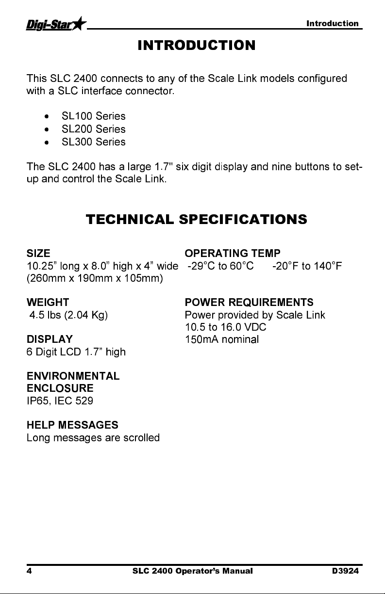
SIZE
10.25” long x 8.0” high x 4” wide
OPERATING TEMP
INTRODUCTION
This SLC 2400 connects to any of the Scale Link models configured
with a SLC interface connector.
•
SL100 Series
•
SL200 Series
•
SL300 Series
The SLC 2400 has a large 1.7" six digit display and nine buttons to set-
up and control the Scale Link.
TECHNICAL SPECIFICATIONS
-29°C to 60°C -20°F to 140°F
(260mm x 190mm x 105mm)
WEIGHT
4.5 lbs (2.04 Kg)
DISPLAY
6 Digit LCD 1.7” high
ENVIRONMENTAL
ENCLOSURE
IP65, IEC 529
HELP MESSAGES
Long messages are scrolled
POWER REQUIREMENTS
Power provided by Scale Link
10.5 to 16.0 VDC
150mA nominal
4 SLC 2400 Operator’s Manual D3924
Page 5
Safety During Use
SAFETY DURING USE
Caution
Cleaning
Do not use running water (high pressure cleaners, hoses) to clean the
indicator or the Scale Link.
Charging Battery and Welding
Disconnect all cables from the weighing indicator and the Scale Link
before charging the battery or welding on the machine. If cables are left
connected, the weighing indicator and connected load cells could be
damaged.
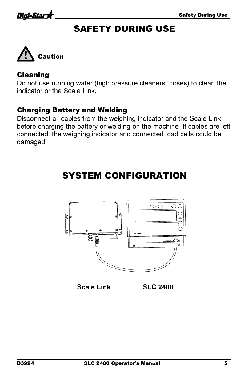
SYSTEM CONFIGURATION
Scale Link SLC 2400
D3924 SLC 2400 Operator’s Manual 5
Page 6
Scale Link Control Overview
1
2
3
4
5
6
7
8
9
10
1
2
3
4
5
6
7
8
9
10
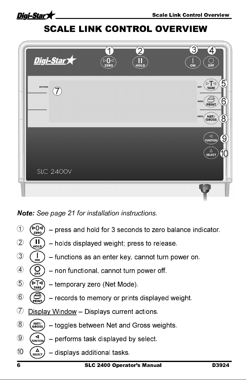
SCALE LINK CONTROL OVERVIEW
Note:
See page 21 for installation instructions.
– press and hold for 3 seconds to zero balance indicator.
– holds displayed weight; press to release.
– functions as an enter key, cannot turn power on.
– non functional, cannot turn power off.
– temporary zero (Net Mode).
– records to memory or prints displayed weight.
Display Window – Displays current actions.
– toggles between Net and Gross weights.
– performs task displayed by select.
– displays additional tasks.
6 SLC 2400 Operator’s Manual D3924
Page 7
Operation
1
2
0
SCALE
1
2
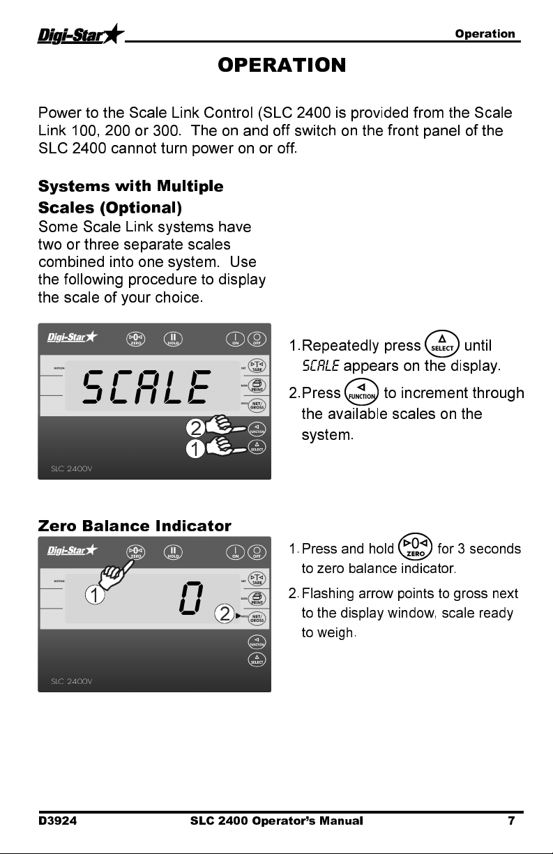
OPERATION
Power to the Scale Link Control (SLC 2400 is provided from the Scale
Link 100, 200 or 300. The on and off switch on the front panel of the
SLC 2400 cannot turn power on or off.
Systems with Multiple
Scales (Optional)
Some Scale Link systems have
two or three separate scales
combined into one system. Use
the following procedure to display
the scale of your choice.
Zero Balance Indicator
1. Repeatedly press until
SCALE
appears on the display.
2
. Press to increment through
the available scales on the
system.
1. Press and hold for 3 seconds
to zero balance indicator.
2. Flashing arrow points to gross next
to the display window, scale ready
to weigh.
D3924 SLC 2400 Operator’s Manual 7
Page 8

Operation
0
300
2
3
4000
1
Tare and Net/Gross
Tare is a temporary zero (Net
Weight) to display total weight
(Gross Weight) Press .
1. Weight displayed, press sets
zero weight.
2. Pressing displays zero weight
and flashing arrow on side of
display points to NET.
3. Add more weight.
8 SLC 2400 Operator’s Manual D3924
Page 9

Operation
4300
300
4
5
1
4300
10JA08 12:01P
ddmmyy
Print Key
Note:
Optional serial port must be
installed for printing.
4. To know total of original weight of
4000 pounds plus added 300
pounds, press to show 4300
pounds, flashing arrow points
GROSS.
5. Press 300 pounds displayed
flashing arrow points NET.
1. Press . Indicator sends data to
printer or PC.
Date in
Weight
4300 LB GR
Time
Gross (GR)
or Net (NET)
D3924 SLC 2400 Operator’s Manual 9
Page 10

Operation
1
TIMER
1
Timer Option
Stopwatch for mixing time.
1. Repeatedly press until
is displayed.
1. Press to displays hours,
minutes and seconds (hh:mm:ss).
TIMER
10 SLC 2400 Operator’s Manual D3924
Page 11

Operation
00
:04:00
1
2
3
4
500
M+
1
RM 500
2
3
Using the M+, RM and CM
Options
Use these options to weigh truck
or wagon one axle at a time.
D3924 SLC 2400 Operator’s Manual 11
1. Repeatedly press moves
flashing digit left.
2. Repeatedly press changes
number.
3. Press to start timer.
4. When timer reaches zero
press to clear timer.
1. Add weight on scale. Example: 500
pounds.
2. Repeatedly press until
displayed.
3. Press
briefly displayed. 500 pounds
added to scale memory and scale in
gross weight mode.
500
pounds and
M+
RM
is
Page 12

Operation
I
000
M+
RM I500
I500
5
6
7
8
9
4
4. Put another weight on scale.
Example: 1000 pounds.
5. Repeatedly press until
displayed.
6. Press scale adds 1000
pounds to 500 pounds in memory
and
RM
flashes.
M+
is
12 SLC 2400 Operator’s Manual D3924
7. Repeatedly press until
displayed.
8. Press .
9. Total of both weights,1500 pounds,
display, scale switches to gross
weight mode.
RM
is
Page 13

Operation
RM
I500
1
2
3
RM
1
Printing Weight from
Memory
Indicator must have optional
printer port for printing.
Weight Averaging
1. Repeatedly press until
displayed.
2. Press shows weight in
memory. Example: 1500 pounds.
3. Press while weight displayed.
1. Repeatedly press until
displayed.
RM
RM
is
D3924 SLC 2400 Operator’s Manual 13
Page 14

Operation
AV
ERAG
750
5
4
COUNT 2
2
3
750
1
Counts
Average
10JA08 12:01P
2. Press twice
seconds performs weight average.
within three
Printing Average Weight
3. Display shows
individual weights to average is two.
Example weight of 1000 pounds
and 500 pounds averaged.
4. Displays
5. Display shows average of two
weights in memory. After displaying
average weight, scale returns to
gross weight mode.
1. Press while average weight is
displayed.
Sample output format shown below:
Date Time
2CT 750LB AV
COUNT 2
AVERAG
if number of
.
Weight
14 SLC 2400 Operator’s Manual D3924
Page 15

Other Functions
1
2
HOLD
1
2
DIMMER
1
2
OTHER FUNCTIONS
Hold
Hold mode prevents displayed
weight from changing while
moving.
Using Dimmer Option
Function and Select keys
1. Press .
2. Press indicator normal.
If weight added in hold mode,
press to cancel hold.
Note:
This feature is disabled on
all legal for trade systems.
1. Repeatedly press until
is displayed.
2. Press dims backlight.
1. Repeatedly press to view
following options:
Timer:
M+:
memory
RM:
CM:
Dimmer:
Menu:
calibrate. See page 16.
Setup:
calibration numbers. See page 20.
Help:
and function key
Stopwatch for mixing time
Adding weigh to weight
Recall weight memory
Clear weight memory
Dimming backlight
View menus 1,2,3,4 and
Change setup and
Explains operation of select
DIMMER
2. Desired option displayed,
press to activate.
D3924 SLC 2400 Operator’s Manual 15
Page 16

Menus and Calibration
English
MENUS AND CALIBRATION
Options changed by user. To display menus 1,2,3,4 and calibrate:
1. Repeatedly press until
2.
Press .
3.
Repeatedly press selects Menu 1,2,3,4 or calibrate.
4.
Press displays setting name and allows value changes.
5.
Press selects options for each setting/display.
6.
Press saves setting and next option for menu displays.
SETTING
[display]
D.A.N
NO.
MENU 1. BASIC FEATURES IN MOST INDICATORS
LANGUAGE
[langag]
DISPLAY RATE
[0 rate]
ZERO TRACK
(ztrack)
WEIGH METHOD
(W mthd)
SCALE ID SETUP
(scalid)
1 PRESS ZERO
(I zero)
101
102
104
105
108 NEW EZ
115
MENU 2. CLOCK, PRINTER,
COMMUNICATIONS FEATURES
TIME FORMAT 201 24 HR
MENU
is displayed.
OPTIONS [displayed]
BOLD=DEFAULT
[ENGLSH)
Dutch
French
German
Italian
Portuguese
Spanish
Danish
Hungarian
Spanish
1,2,3,4
ON/
OFF
1=General,
2=Fast,
3=Slow,
4=Lock-On
ON/
OFF
[NEDERL]
[FRANCS]
[DEUTSH]
(ITAL]
(PORT]
(ESPAN]
(DANSK]
(MAGYAR]
(VESTA]
DESCRIPTION
Select language to be
displayed.
Update display times per
second.
If ON -zero track adjust
balance for build up of snow &
mud.
Select weigh method
Identity of scale location (truck
id or Mixer number).
If ON -press and hold Zero
key to Zero/Balance scale.
16 SLC 2400 Operator’s Manual D3924
Page 17

Menus and Calibration
data prints on one
SETTING
[display]
(time f)
1 TIME
(time)
DATE FORMAT
(date f)
DATE
(date)
TARE AUTO
PRINT
(tareap)
ONE LINE PRINT
(Il prt)
AUTO PRINT
(aprint)
PRINT FORMAT
(prtfmt)
D.A.N
NO.
202 XX:XX:XX
203
204 Enter XXXXXX
211
212
214
216
OPTIONS [displayed]
BOLD=DEFAULT
AM/PM
1-mm-dd
2-mm/dd/yy
3-mm/dd/yyyy
4-dd-mm
5-dd/mm/yy
6-dd/mm/yyyy
7-ddmoyy
8-ddmoyyyy.
ON/
OFF
ON/
OFF
ON/
OFF
AUTO
WTONLY
DOWNLD
DT+TM
ID+TM
IDWTTM
ANIMAL
3200-A
3200-B
32-TMR
DATCH1
FDINFO
WTRCTM
EIDINF
EID
EIDVID
DESCRIPTION
Select time format -AM/PM or
24 hour
Select key changes time,
function key chooses
hh:mm:ss.
Select date format
Select key changes date -
function key chooses
mm/dd/yy .
If ON -tare auto-prints
displayed weight.
If ON -scale
line.
If ON -pressing keys auto-
prints weight values.
Select alternate & comma
(CSV) formats.
D3924 SLC 2400 Operator’s Manual 17
Page 18

Menus and Calibration
20ma
SETTING
[display]
REMOTE
(REMOTE)
ZERO OUTPUT
(zerout)
SCALE NUMBER
(scl no)
REMOTE
DISPLAY
(rmdisp)
ANALOG LOW
WEIGHT
(LOW WT)
ANALOG HIGH
WEIGHT
(HIGHWT)
ANALOG SELECT
(ANAOUT)
MENU 3. SCALE CALIBRATION SETTINGS
DISPLAY UNIT
(lb-kg)
D.A.N
NO.
218
219
231
234
241
242
243
301
OPTIONS [displayed]
BOLD=DEFAULT
ON
/OFF
EZ3MUX
EZ2
.01,.02,.05,.1,.2,.5,1,2,5,
10
,20, 50,100
DESCRIPTION
If ON scale communicates
with cab control display
Perform Zero/Balance for
SCOREM #11 weight output
and analog output (4-20mA)
Select scale number for cab
control communication
Select type of remote display
Enter analog weight value to
equal 4mA or 0 volts
Enter analog weight value to
equal 20mA or 5 volts
Select 0-5V,4-20ma or 0-
output
Select display count size of
weigh values.
CAPACITY
(cap)
WM1 ADJUST 1
(wmaI-I)
LB
303
304 40000
/KG
Display pounds -lb or
kilograms -kg
Enter MAXIMUM weight
measurable on scale.
MENU 4. PRESET, BATCHING & ROTATION COUNTER
FEATURES
Does not apply to 2400 indicator
CALIBRATION
DEAD WEIGHT
CAL
(CAL)
SETUP NUMBER
(SETUP)
CALIBRATION
NUMBER
(CAL)
18 SLC 2400 Operator’s Manual D3924
802
871
872
Calibration method using
weights
Quick entry method selects
weigh method 1-4lbs, 5-8 kg,
gain 1-9, display counts 1-9
and capacity *1000
Weight displayed at 0.4mV/V
for these load cells
Page 19

Re-Calibrating Your Scale
RE-CALIBRATING YOUR SCALE
To re-calibrate your scale and make it even more accurate, document
several loads of varying sizes and measure the actual weight of all
loads on a certified scale.
In this example, we are unloading six loads onto four semi-trucks.
Example:
Load A 51560
Load B 33240
Load C 17620
Load D 50420
Load E 38200
Load F 12360
Total Indicator Weight 203400
Truckload #1 51920
Truckload #2 51320
Truckload #3 50720
Truckload #4 51070
Total Certified Weight 205030
Reading Too High
If the Indicator is reading higher than the certified scale, then the
calibration number is high and should be decreased proportionally. See
page 20.
Reading Too Low
If the Indicator is reading lower than the certified scale, then the
calibration number is low and should be increased proportionally. See
page 20.
D3924 SLC 2400 Operator’s Manual 19
Page 20

Re-Calibrating Your Scale
1
I
46040
2
3
4
5
4
4
3
3
24280
1
Get your Calibration
Number
Change Set up and
Calibration Numbers
1. Enter
1. Repeatedly press until
872
and press . The
calibration (
display. Example
is displayed.
CAL
) number will
CAL = 24280.
SETUP
2. Press .
3. Six digit setup number displayed.
Change number, press moves
flashing position left. Press
20 SLC 2400 Operator’s Manual D3924
changes number.
4. Press stores setup number.
Indicator displays
number by pressing
and .
5. Press to exit.
CAL
, change
Page 21

Installation
RAIL MOUNT
WING MOUNT
WEDGE MOUNT
RAM MOUNT
INSTALLATION
Indicator Mounting
KEY
PART
DESCRIPTION
NUMBER
A 404353 BRACKET-EZ3 PLASTIC RAIL *
B 403780 SCR-#10 X 5/8 FHSTS BLACK ZP
C 840459 SUPPORT-HAT BRACKET
D 405069 U-BOLT 1/4-20 X 3.25 ZP
E 405084 NUT-1/4-20 TOP LOCKING FLANGE
F 403770 BRACKET- WING MOUNT *
G 405124 PACK-WEDGE MOUNT BRACKET
WITH U-BOLTS & FLANGE NUTS
H 405244 EZ3 WEDGE MOUNT
KEY
PART
DESCRIPTION
NUMBER
I 404799 RAM MOUNT FOR EZ III INDICATOR
WITH HARDWARE
J 404230 RAM SUCTION CUP W/TWIST LOCK
D3924 SLC 2400 Operator’s Manual 21
Page 22

Optional Equipment
OPTIONAL EQUIPMENT
Transmitter/Receiver
Features
•
Wireless remote with full
key control of indicator on
mixer
•
Mount remote in easy view
of loading
•
Improves loading accuracy
Functions
•
Communicates with
multiple mixers
Transmitter (shown) with factory
installed receiver in indicator. Use
to zero indicator from a remote
location. Operating range about 90
feet.
22 SLC 2400 Operator’s Manual D3924
 Loading...