


US Part Number: D3570A 10/24/2001

Digi-Star EZ3200/EZ3200V/EZ3200V RC |
Table of contents |
|
Table of contents |
|
|
1. |
About the product.............................................................................................................................. |
1 |
|
FEATURES OF MODELS EZ3200, EZ3200V AND EZ3200V RC ................................................ |
1 |
|
OPERATING SPECIFICATIONS.................................................................................................... |
1 |
|
HOUSING.......................................................................................................................................... |
1 |
2. |
Mounting and connection ................................................................................................................. |
2 |
|
INDICATOR MOUNTING ............................................................................................................... |
2 |
|
POWER CONNECTION................................................................................................................... |
2 |
|
POWER CABLE CONNECTIONS .................................................................................................. |
2 |
|
INDICATOR BOTTOM PANEL CABLE CONNECTIONS ........................................................... |
2 |
|
REMOTE ALARM CONNECTION ................................................................................................. |
2 |
|
REMOTE INPUT CONNECTION................................................................................................... |
2 |
|
LOAD CELL CONNECTION........................................................................................................... |
3 |
|
LIGHTNING PROTECTION ........................................................................................................... |
3 |
|
TECHNICAL MANUAL ................................................................................................................... |
3 |
3. |
Setup and Calibration Requirements .............................................................................................. |
4 |
|
TO RUN THE SELF TEST............................................................................................................... |
4 |
4. |
Matching EZ scale to another scale ................................................................................................. |
5 |
|
SCALE MATCHING EXAMPLE ..................................................................................................... |
5 |
|
SCALE INFORMATION SHEET .................................................................................................... |
5 |
|
SCALE MATCHING WORK SHEET .............................................................................................. |
5 |
|
CONNECTING EZ INDICATOR TO OTHER LOAD CELLS ....................................................... |
6 |
|
TO CHANGE THE SETUP & CALIBRATION NUMBERS .......................................................... |
6 |
|
TO RETURN TO WEIGH MODE .................................................................................................... |
7 |
5. |
Getting started .................................................................................................................................. |
8 |
6. |
System operation............................................................................................................................... |
9 |
|
TURNING ON THE SCALE ............................................................................................................ |
9 |
|
TURNING OFF THE SCALE .......................................................................................................... |
9 |
|
TO ZERO BALANCE THE SCALE ................................................................................................. |
9 |
|
USING THE HELP KEY................................................................................................................ |
10 |
|
TO SELECT GROSS MODE .......................................................................................................... |
10 |
|
TO SELECT NET MODE ............................................................................................................... |
10 |
|
TO SELECT HOLD MODE............................................................................................................ |
11 |
|
TO EXIT HOLD MODE.................................................................................................................. |
11 |
|
TO CANCEL HOLD MODE ........................................................................................................... |
11 |
|
TO ENTER A PRESET................................................................................................................... |
12 |
|
TO CLEAR THE PRESET ALARM ............................................................................................... |
13 |
|
TO CLEAR THE PRESET ALARM USING THE TR OPTION................................................... |
13 |
|
TO PRELOAD A TARE VALUE .................................................................................................... |
14 |
|
TO USE THE PRE-ALARM ........................................................................................................... |
15 |
|
TO CHANGE THE PRE-ALARM VALUE .................................................................................... |
15 |
|
TO START THE MIX TIMER ........................................................................................................ |
16 |
|
TO CLEAR THE MIX TIMER........................................................................................................ |
16 |
|
TO RESTART THE MIX TIMER ................................................................................................... |
16 |
|
TO START THE ROTATION COUNTER ..................................................................................... |
17 |
|
TO CLEAR THE ROTATION COUNTER..................................................................................... |
17 |
|
TO RESTART THE ROTATION COUNTER................................................................................ |
17 |
|
PROGRAMMING RECIPES .......................................................................................................... |
18 |
|
TO PROGRAM A NEW RECIPE ................................................................................................... |
19 |
|
TO CHANGE THE ENTRY METHOD.......................................................................................... |
20 |

Digi-Star EZ3200/EZ3200V/EZ3200V RC |
Table of contents |
|
6. |
System operation (continued)......................................................................................................... |
21 |
|
TO EDIT A RECIPE ....................................................................................................................... |
21 |
|
TO ERASE A RECIPE.................................................................................................................... |
22 |
|
TO PRINT A SINGLE RECIPE ..................................................................................................... |
23 |
|
TO PRINT ALL RECIPES.............................................................................................................. |
23 |
|
USING THE AUTO ADVANCE FEATURE ................................................................................. |
24 |
|
TO CHANGE THE TOLERANCE ................................................................................................. |
24 |
|
USING DELAY TIME .................................................................................................................... |
25 |
|
TO CHANGE THE DELAY TIME ................................................................................................. |
25 |
|
TO LOAD A BATCH USING A RECIPE....................................................................................... |
25 |
|
TO MANUALLY ADVANCE TO NEXT INGREDIENT .............................................................. |
27 |
|
TO REVIEW A RECIPE ................................................................................................................. |
27 |
|
TO REVIEW INGREDIENT ACCUMULATION.......................................................................... |
28 |
|
TO PRINT ACCUMULATION FOR ONE INGREDIENT........................................................... |
28 |
|
TO PRINT ACCUMULATION FOR ALL INGREDIENTS.......................................................... |
28 |
|
TO PRINT THE INGREDIENT TABLE ....................................................................................... |
29 |
|
TO RENAME INGREDIENTS....................................................................................................... |
29 |
|
TO ERASE ACCUMULATION FOR ONE INGREDIENT .......................................................... |
30 |
|
TO ERASE ACCUMULATION FOR ALL INGREDIENTS......................................................... |
31 |
7. |
Optional features............................................................................................................................. |
32 |
|
REMOTE DISPLAY........................................................................................................................ |
32 |
|
TR: RADIO CONTROL OPERATION ........................................................................................... |
32 |
|
PRINT WEIGHT DATA.................................................................................................................. |
32 |
|
CLOCKOPTION.............................................................................................................................. |
32 |
|
ID# OPTION.................................................................................................................................... |
32 |
|
TO ENTER ID NUMBER............................................................................................................... |
32 |
|
TO DISPLAY ID NUMBER............................................................................................................ |
32 |
|
TO USE FUNCTION & SELECT KEYS ....................................................................................... |
33 |
|
TO ADD WEIGHT TO WEIGH MEMORY ................................................................................... |
34 |
|
RECALL WEIGH MEMORY.......................................................................................................... |
34 |
|
PRINT WEIGHT MEMORY........................................................................................................... |
34 |
|
CLEAR WEIGH MEMORY ............................................................................................................ |
34 |
|
WEIGH AVERAGING .................................................................................................................... |
35 |
|
BLACK OUT.................................................................................................................................... |
35 |
|
PULSED OUTPUT ......................................................................................................................... |
36 |
APPENDIX 1: Ingredient names ....................................................................................................... |
37 |
|
APPENDIX 2: Examples..................................................................................................................... |
38 |
|
Always keep this manual by your scale indicator
All rights reserved. Reproduction of any part of this manual in any form whatsoever without Digi-Star’s express written permission is forbidden. The contents of this manual are subject to change without notice. All efforts have been made to assure the accuracy of the contents of this manual. However, should any errors be detected, Digi-Star would greatly appreciate being informed of them. The above notwithstanding, Digi-Star can assume no responsibility for any errors in this manual or their consequence.
Copyright ! 2001 Digi-Star.
Fort Atkinson, Wisconsin (USA)

Digi-Star Model EZ3200/EZ3200V/EZ3200V RC |
1. About the product |
1. About the product
FEATURES OF MODELS EZ3200, EZ3200V AND EZ3200V RC
"Three recipe programming modes
-Ingredient percentage of total
-Amount per animal
-Amount per ingredient
"Accumulation for tracking ingredient usage
"200 Recipe memory locations
"99 Programmable ingredient names to simplify loading & unloading
"Ingredients can be entered in any order
"Scrolling Help messages for easy recipe programming & operation
"Front panel calibration without simulator or weights
"[Select] and [Function] keys to simplify appearance and allow for future expansion
"A Hold feature to hold the weight stable while moving the scale system
"Large 1.7" display for greater readability (1" for Model 3200)
"Fiber-optic back lighting for extremely long life
"Expanded self diagnostic test capability
"New powerful microprocessor and expanded memory
OPERATING SPECIFICATIONS
" |
Temperature range: |
-28#C to 60#C (-20#F to 140#F) |
" |
Power requirements: |
10.2Vdc - 16Vdc |
" |
Power on: |
160mA, 4L.C. 350$ |
" |
Power off: |
1mA |
HOUSING |
|
|
" |
Size (l×h×w): |
10.3" × 7.2" × 5.0" (262 × 183 × 127 mm) |
" |
Weight (unpacked): |
4.5 lbs (2.04kg) |
"Display EZ3200: 6-digit alpha numeric LCD, fiberoptic back lighting
Display height EZ3200 = 1" (25.4 mm)
Display height EZ3200V and 3200V RC = 1.7" (43.2 mm)
"Environmental enclosure: IP65, IEC529
" Connectors: |
AMP, gold plated contacts |
1
! copyright - 10/24/2001

Digi-Star Model EZ3200/EZ3200V/EZ3200V RC |
2. Mounting and connection |
2. Mounting and connection
INDICATOR MOUNTING
The indicator is easily attached to the Indicator Mounting Bracket by hooking the top over the plate and securing the bottom with two screws and nuts (size# 10 - 24 × 5/8" or M5 × 16mm).
POWER CONNECTION
 Warning!
Always disconnect the indicator power cord before “jump starting” or fast charging a battery. Disconnect all indicator leads before welding on equipment. Failure to do so can cause surges which will damage the scale.
The power cable should be connected directly to a vehicle battery or regulated power supply. The scale end of the power cable is attached to the J901 connector located on the bottom panel of the scale.
Connect the RED wire from the power cable to +12VDC and the BLACK wire to GROUND. The indicator is fused internally at 4 amps.
POWER CABLE CONNECTIONS |
INDICATOR BOTTOM PANEL |
|
CABLE CONNECTIONS |
Wire Color |
|
Wire Function |
RED |
|
Battery (+12Vdc) |
BLACK |
|
GROUND |
ORANGE |
|
Remote Alarm Out+ |
BLUE |
|
Remote Input |
|
|
|
REMOTE ALARM CONNECTION
If a remote 12 Vdc alarm is to be used, connect the +12Vdc side of the alarm to the power cable ORANGE wire and the GROUND side of the alarm to the frame (= ground).
Serial |
Remote |
Junction |
Power |
Port |
Display |
Box |
Cable |
Cable |
Cable |
Cable |
|
(Optional) |
(Optional) |
|
|
!The alarm output is fused for a maximum drain of 10 amps. The remote alarm connection may also be used for motor control purposes when used with a relay.
REMOTE INPUT CONNECTION
If the remote input is to be used, connect one side of the normally open momentary switch or relay contact to the power cable BLUE wire, and the other side to the frame or other GROUND connection. If your power cable does not contain a blue wire and you desire to use this feature, contact your dealer for a special cable. A process control box is available for motor control and remote enter preset capability.
2
! copyright - 10/24/2001

Digi-Star Model EZ3200/EZ3200V/EZ3200V RC |
2. Mounting and connection |
LOAD CELL CONNECTION
The indicator operates with strain gage load cells. The system is normally supplied with a J-BOX cable going between the scale indicator and the load cell junction box. Extension Kits are available from your dealer in various lengths.
To connect the load cells, attach the junction box cable to the J902 connector on the bottom panel of the scale. Connect the load cell cables to the junction box as shown left.
Terminal Color |
Description |
WHITE |
SIGNAL + |
GREEN |
SIGNAL - |
RED |
EXCITATION + |
BLACK |
EXCITATION - |
SHIELD |
SHIELD |
!Follow color key on circuit board to insure proper connection of load cell wires.
to J902 connector of indicator
LIGHTNING PROTECTION
Additional protection can be achieved with the proper installation of grounding rods. Please call (920) 563-1400 to request Digi-Star Form F3050.
TECHNICAL MANUAL
Technical Manual available upon request. Please call (920) 563-1400 to request Digi-Star Manual for New EZ3200.
3
! copyright - 10/24/2001

Digi-Star Model EZ3200/EZ3200V/EZ3200V RC |
3. Setup and Calibration Requirements |
3. Setup and Calibration Requirements
 Warning!
This indicator was calibrated at the factory to weigh accurately with your system. Additional calibration is not necessary under normal conditions.
The Short Form Setup & Calibration procedure allows you to change the SETUP and CAL numbers of the indicator. You may want to perform this procedure if:
1.the indicator is being connected to different load cells, or
2.you want to adjust the calibration to match another scale system (chapter 4).
Before continuing, first write down the current SETUP and CAL numbers of your EZ indicator. These numbers are displayed during the Self Test.
TO RUN THE SELF TEST
1.With the indicator already ON, press  to start the Self Test.
2.Press  to "pause" the Self Test while numbers are displayed.
3.Press  again to "resume".
SETUP # |
|
CAL # |
|
!Do not attempt to calibrate the scale if the indicator is not reading stable weights. The calibration procedure will not fix instability, inconsistencies, or flashing "RANGE" messages.
4
! copyright - 10/24/2001

Digi-Star Model EZ3200/EZ3200V/EZ3200V RC |
4. Matching EZ scale to another scale |
4. Matching EZ scale to another scale
Sometimes two different scales are used to weigh the same load. When this is done, the weight measured by each scale may not be the same. This can be caused by one or both of the two scales being slightly out of calibration. This indicator has the ability to match any other scale, even if that scale is not calibrated.
To match your EZ scale (Scale A) to another scale (Scale B) you must determine the Calibration Multiplier. To do this, place a load on Scale A (feed wagon, etc...) and write down the weight displayed. Repeat several times to determine the average weight. Next, place the same load on Scale B and again write down the weight displayed.
Repeat several times to determine the average weight. Use the following formula to determine the Calibration Multiplier for the EZ’s "CAL" number:
! It is important to use an average of several weights before calibrating the scale.
SCALE MATCHING EXAMPLE
|
Original |
|
SETUP # |
127060 |
|
|
||||
|
|
|
|
CAL# |
23980 |
|
|
|||
|
|
|
|
|
|
|
|
|
|
|
|
|
|
|
|
1 trial |
|
|
2 trial |
|
3 trial |
|
Scale B |
|
|
|
30,000 |
|
|
30,580 |
|
28,000 |
|
Scale A |
|
|
29,440 |
|
|
29,800 |
|
27,500 |
|
|
B ÷ A |
|
|
|
1.020 + |
|
|
1.026 + |
|
1.018 = 3.064 |
|
|
3.064 ÷ 3 trials = 1.021 Cal. Multiplier |
|
|
||||||
|
|
|
|
|
||||||
|
New EZCAL# |
= |
Orig. EZCAL# |
× |
|
Cal.Multiplier |
|
|
||
24484 |
|
|
= |
23980 |
× |
1.021 |
|
|
||
! You should not modify your "SETUP" number. Only your "CAL" number.
Follow the instructions: TO CHANGE SETUP/CALIBRATION NUMBERS shown on the next page.
|
SCALE INFORMATION SHEET |
|
|
||||||
|
Original |
SETUP # .................. |
|
|
|
|
|
||
|
|
|
|
CAL# .................. |
|
|
|
|
|
|
SCALE MATCHING WORK SHEET |
|
|
||||||
|
|
|
|
|
|
|
|
|
|
|
|
|
|
1 trial |
|
|
2 trial |
|
3 trial |
|
Scale B |
|
|
|
|
|
|
|
|
|
Scale A |
|
|
|
|
|
|
|
|
|
B ÷ A |
|
|
|
|
|
|
|
|
|
|
|
÷ 3 trials = |
|
|
Cal. Multiplier |
|
|
|
|
|
|
|
|
|
|
|
||
|
New EZCAL# |
= Orig. EZCAL# |
× Cal.Multiplier |
|
|
||||
|
........................ |
|
|
= ....................... |
× .......................... |
|
|
||
5
! copyright - 10/24/2001

Digi-Star Model EZ3200/EZ3200V/EZ3200V RC |
4. Matching EZ scale to another scale |
CONNECTING EZ INDICATOR TO OTHER LOAD CELLS
1 SETUP 2 and
CHANGE SETUP AND
CALIBRATION VALUES
127060
127062 1
2
CAL
You will need the number and type of load cells used in the new scale system. You will also need the current "SETUP" and "CAL" as described above. Once you have written down this information, contact your nearest Scale Service Center for new "SETUP" and "CAL" numbers.
Follow the instructions “To Change the Setup / Calibration Numbers” shown below.
Press and hold the  key, then press the
  key, to enter Short Form Setup & Calibration.
The first message displayed is SETUP.
Next, the actual SETUP number is displayed.
! Press the  key for additional help information during Setup and Calibration.
If the correct SETUP number is displayed, press the  key to advance to the CAL number.
1.Press the  key to cause the “flashing” digit to count upward.
2.Press the  key to select which digit is flashing.
When the correct SETUP number is displayed, press the  key to advance to the CAL number.
This displays the CAL message, followed by the CAL number.
! The CAL number is not a weight. It is a reference value the indicator uses to determine the weight. This number directly affects the accuracy of the scale system.
Change the CAL number using the same method described in Steps 1& 2. When the display shows
the correct number, press the  key.
key.
This causes the number to be stored permanently in the indicator and returns the indicator to the weighing mode.
6
! copyright - 10/24/2001
Digi-Star Model EZ3200/EZ3200V/EZ3200V RC 4. Matching EZ scale to another scale
TO RETURN TO WEIGH MODE |
To exit setup without changing any |
values, press |
|
|
and hold the |
key, then press the |
key. |
and
2
1
7
! copyright - 10/24/2001
Digi-Star Model EZ3200/EZ3200V/EZ3200V RC |
5. Getting started |
5. Getting started
To operate the scale, first attach the scale's power cord to connector J901 and the loadcell cable to connector J902 on the bottom panel of the scale.
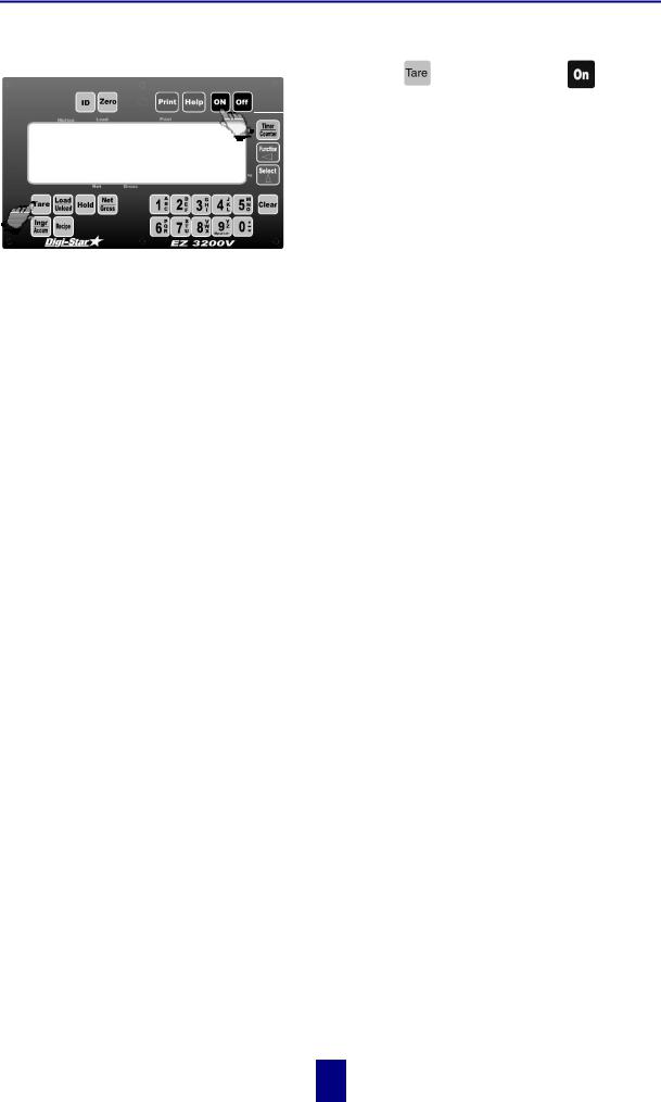
Press the  key. A brief message is displayed (such as HELLO).
HELLO

The scale enters the GROSS mode.
A warm up period of ten to fifteen minutes provides the most accurate readings. If the scale is holding a load for a long period of time (ex. overnight), the weight displayed may vary because of zero shift created by changes in temperature. This does not affect the accuracy of the scale.
For example, if the system was loaded with 1000lbs, it might read 1200lbs the following day. The change in temperature "zero shifted" the ZERO/BALANCE from 0 to 200lbs. When unloading the scale, the display will count from 1200 to 200lbs for a total of 1000lbs.
After this warm up period, press and release  . Then, within three seconds, press
  . The word ZERO is displayed to show completion of the ZERO/BALANCE step.
Now the scale is ready to weigh!
8
! copyright - 10/24/2001
Digi-Star Model EZ3200/EZ3200V/EZ3200V RC |
6. System operation |
6. System operation
!EZ3200 V shown - EZ3200 and ES3200V RC operations are the same.
!LB and KG annunciators are located along right hand edge of the 3200V display.
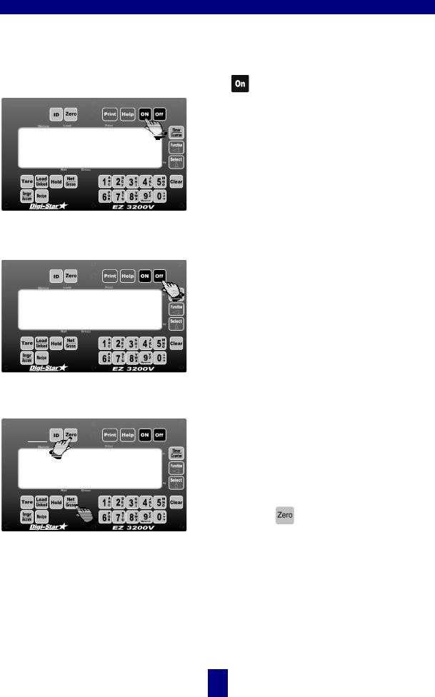
TURNING ON THE SCALE
HELLO
TURNING OFF THE SCALE
TO ZERO BALANCE THE SCALE
and
zero
Press .
A brief message will be displayed (such as HELLO). The scale then enters the GROSS weighing mode.
GROSS mode displays the weight change since the unit was last ZERO/BALANCED.
Pressing  a second time during normal system operation starts the self test.
Press  .
.
Press and then within three seconds, press
 .
.
The [Zero] key will "balance off" empty trailer, bin, or platform weight.
The message ZERO is displayed to show completion of the step and the scale is placed in the GROSS mode.
Pressing only will cause the message: TO
ZERO/BALANCE PRESS NET/ GROSS - THEN ZERO to be displayed.
If the supply power is below the low battery threshold (10.5 Volts), the message CANNOT balance -- LOW BATTERY VOLTAGE is displayed. The message LO BAT will be periodically shown on the display (approx. every five seconds) to alert the operator of the low battery condition.
Loss of power does not affect the Zero/Balance or Setup/Calibration values.
9
! copyright - 10/24/2001

Digi-Star Model EZ3200/EZ3200V/EZ3200V RC |
6. System operation |
USING THE HELP KEY
 provides additional information about the weighing modes, setup/calibration, and recipe programming.
Pressing  while displaying weight will display information about the last key pressed.
TO SELECT GROSS MODE
9850
%
Gross Mode displays the weight change since the unit was last Zero/Balanced.
1. Press  .
.
! The scale is in Gross Mode if there is a flashing arrow (%) pointing toward the word Gross, next to the display.
TO SELECT NET MODE |
Net Mode displays the weight change after a |
|
Tare has been performed. Tare creates a |
|
temporary zero at that weight value. |
|
% |
0 ! |
||||||
or |
1 |
|
|
2/3 |
|
|
||
|
|
|
|
|
|
|
|
|
3. If in Load/Unload Mode, press 
1.Press  to set a temporary "zero" point and enter the Net Mode.
or
2.If in Gross Mode, press  .The [Net/Gross] key is an alternating action key. If the scale is in the Gross Mode, pressing the [Net/Gross] key will place it in the Net Mode. If the scale is in the Net Mode, pressing the [Net/Gross] key will place it in the Gross Mode.
two times to place the scale in Net Mode.
!If the Tare Function has not been previously performed, the unit will stay in the Gross Mode and the message FOR NET MODE PRESS TARE will scroll across the display.
The scale is in Net Mode if there is a flashing arrow (%) pointing toward the word Net, just above the [Hold] and [Net/Gross] keys.
10
! copyright - 10/24/2001
Digi-Star Model EZ3200/EZ3200V/EZ3200V RC |
6. System operation |
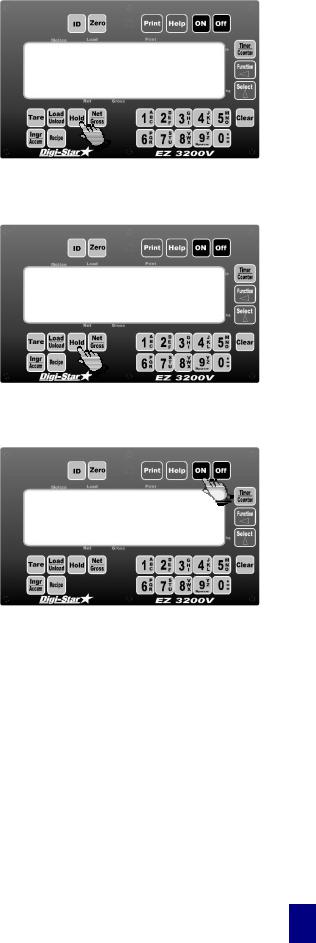
TO SELECT HOLD MODE
hold
TO EXIT HOLD MODE
9850% !
TO CANCEL HOLD MODE
9850!
%
Hold Mode prevents the displayed weight from changing due to “zero shift” while moving the scale.
Press  to "hold" the displayed weight and enter the Hold Mode.
! The scale is in Hold Mode if the word HOLD is flashing on the display and the flashing hold weight is only displayed for a brief time.
Press  .
.
At this time the scale reactivates and adjusts the Zero/Balance to maintain the gross weight displayed. Small changes in weight can occur while moving the scale system to new locations for loading or unloading. This change is called "zero shift" and is due to several factors including terrain changes and mechanical stresses.
Press  .
.
Cancelling the Hold Mode prevents the scale from adjusting the Zero/Balance and returns the system to the normal weighing mode.
Use this if weight is accidentally added while scale is still in Hold Mode.
11
! copyright - 10/24/2001
 Loading...