


RF

Operators Manual
Fort Atkinson, Wisconsin USA
Panningen, The Netherlands
www.digi-star.com
D3664-US Rev H August 2008

RF DataLink
D3664-H

Operators Manual
D3664


Operators Manual
RF DataLink Setup 1
Sequence of Operations .............................................. 1
Registering the Software.............................................. 1
Radio Installation and Setup ........................................ 1
Radio Antennas ........................................................... 2
Fresnel Zone................................................................ 3
Radio Interference ....................................................... 3
Standard Range Setup ................................................ 3
Extended Range Setup................................................ 4
USB Black Box Installation .......................................... 5
Passwords ................................................................... Error! Bookmark not
defined.
Entering Mixer Data ......................................................... 5
Adding Mixers .............................................................. 5
Defaults............................................................................ 7
Determining the System Defaults. ............................... 7
Defaults – Processing Design...................................... 7
Modes .......................................................................... 7
Auto ............................................................................. 7
Interactive with Mill ...................................................... 7
Loads Made by Bunk Reader ...................................... 8
Stationary List, Truck Loads ........................................ 8
Bunk Reader All Mixers ............................................... 8
Auto Start Processing .................................................. 8
Verify Ingredient Checksum......................................... 8
Weigh Units ................................................................. 8
Archive Data ................................................................ 8
Defaults - File Directories............................................. 8
Make As Fed Data File ................................................ 9
Defaults - Pen Feeding ................................................ 10
Base Radio Type ......................................................... 10
Radio Test Mode ......................................................... 10
Defaults – Pen Feeding ............................................... 11
Pen Delivery Mode....................................................... 11
Resizing at Scale (Send 95% of Capacity) .................. 11
Optimize Load to Pens/Optimize-Split Pens ................ 11
Find Pens to Fit............................................................ 12
Defaults – Feed Tolerances......................................... 13
Split Load Minimum Balance ....................................... 13
Pen Delivery Validate Tolerances................................ 13
Auto Add Pen Back on List to Feed ............................. 14
Defaults – Mixer Loading ............................................. 14
Determining Load Size for the Mixer............................ 14
Feedings To Mixer ....................................................... 14
D3664

RF DataLink
Full Load Delay............................................................ 15
Defaults – Delivery Sorting .......................................... 15
Print Mixer Load Sheet ................................................ 16
Operating the RF DataLink 17
Importing the Feeding Data ......................................... 17
Starting the Process .................................................... 17
How the Process Works............................................... 18
Modifying Ration Data.................................................. 19
Adding Ingredients....................................................... 20
Modifying Pen Data...................................................... 20
Changing Pen Rations................................................. 21
Deleting Pens .............................................................. 21
Adding Pens ................................................................ 21
Changing the Pen Order .............................................. 21
Putting an In-Process Pen back in the Feeding ........... 23
Deleting Records ......................................................... 23
Test Communications .................................................. 24
Indicator Status............................................................ 24
Reliability Meter ........................................................... 25
Utilities ......................................................................... 25
Repair Parts – Std. Antenna ........................................ 27
Repair Parts – Extend Range Antenna........................ 28
Operators Manual
RF DataLink Setup
Sequence of Operations
After installing your software, please follow this section to setup the RF Datalink for use. It
is important that you follow along with this sequence.
Registering the Software
Once the software has been installed, it must be registered. Contact Digi-Star to obtain
your registration code. The code is case sensitive; all letters must be entered in upper
case.
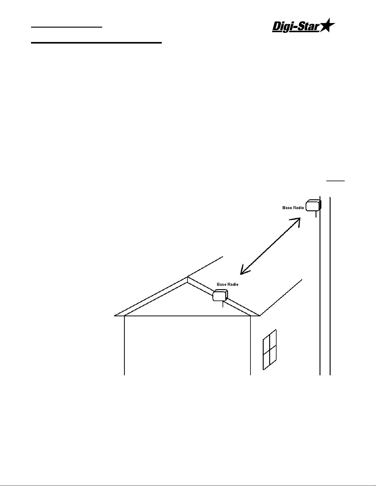
Radio Installation and Setup
When installing the base radio; make sure the “ram mount” is fully extended away from the
mounting surface.
For greater radio communication and range mount the radio in the highest position that it is
visible from the ground or were the mixers are being loaded. Mount the radio in either
position like the illustration. On the corner of the office or on a utility pole.
D3664
1
RF DataLink
Radio Antennas
The location of the antennas is critical. Check the installation of the antennas and the
antenna location.
Indicator and Truck Mounted Antenna: Truck Mounted Antenna, mount the antenna
outside, on the top of the cab, in the center of the roof. Do not modify the cable between
Truck Mounted Antenna and the indicator.
Yes No Are any building near the Base Station Antenna metal?
Yes No Are any metal structures located between the Base Station Antenna and
the mixers?
Yes No When standing at the Base Station Antenna, can you see the mixer?
Yes No Have any of the antenna cables been modified?
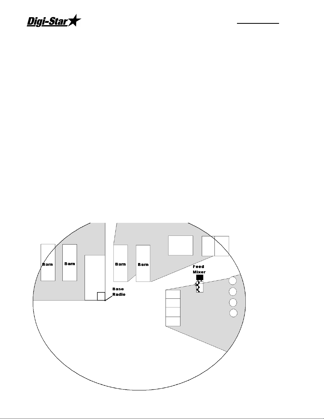
Radio Range:
The picture below shows how radio range would be affected by obstructions like metal
barns or earth. The gray areas show poor radio signal. If the radio is mounted higher, this
may improve radio range.
2
Operators Manual
Fresnel Zone
The Fresnel Zone can be thought of as a football-shaped tunnel between two sites that
provides a path for RF signals.
In order to achieve the greatest range, the football-shaped path in which radio waves travel
must be free of obstructions. Buildings, trees or any other obstacles in the path will
decrease the communication range. If the antennas are mounted just barely off the ground,
over half of the Fresnel Zone ends up being obstructed by the earth resulting in significant
reduction in range. To avoid this problem, the antennas should be mounted high enough off
the ground so that the earth does not interfere with the central diameter of the Fresnel Zone.
Minimal height of base radio:
Range Distance Height
1000 ft (305 m) 15 ft (4.6 m)
1 Mile (1.61 km) 25 ft (7.6 m)
1.5 Miles (2.42 km) or more 45 ft (13.7 m)
If you do not have enough cable from the computer to the radio there are different cable
lengths that Digi-Star offers, or you would like a higher powered antenna, contact Digi-Star.
Standard length is 150 ft / 45.75 m (RS-232). Extended length is 150 ft / 45.75 m (RS-422)
or custom lengths are available (150+)
Radio Interference
There are many types of wireless networks or (WIFI) and some can interfere with the
DataLink radio. If DataLink is still showing radio interference, check the WIFI network
number. Changing this number can correct for radio interference. For further information
about WIFI, check the website of the brand of your radio. 802.11 2.4GHZ use channels 1 –
6 and 13 & 14.
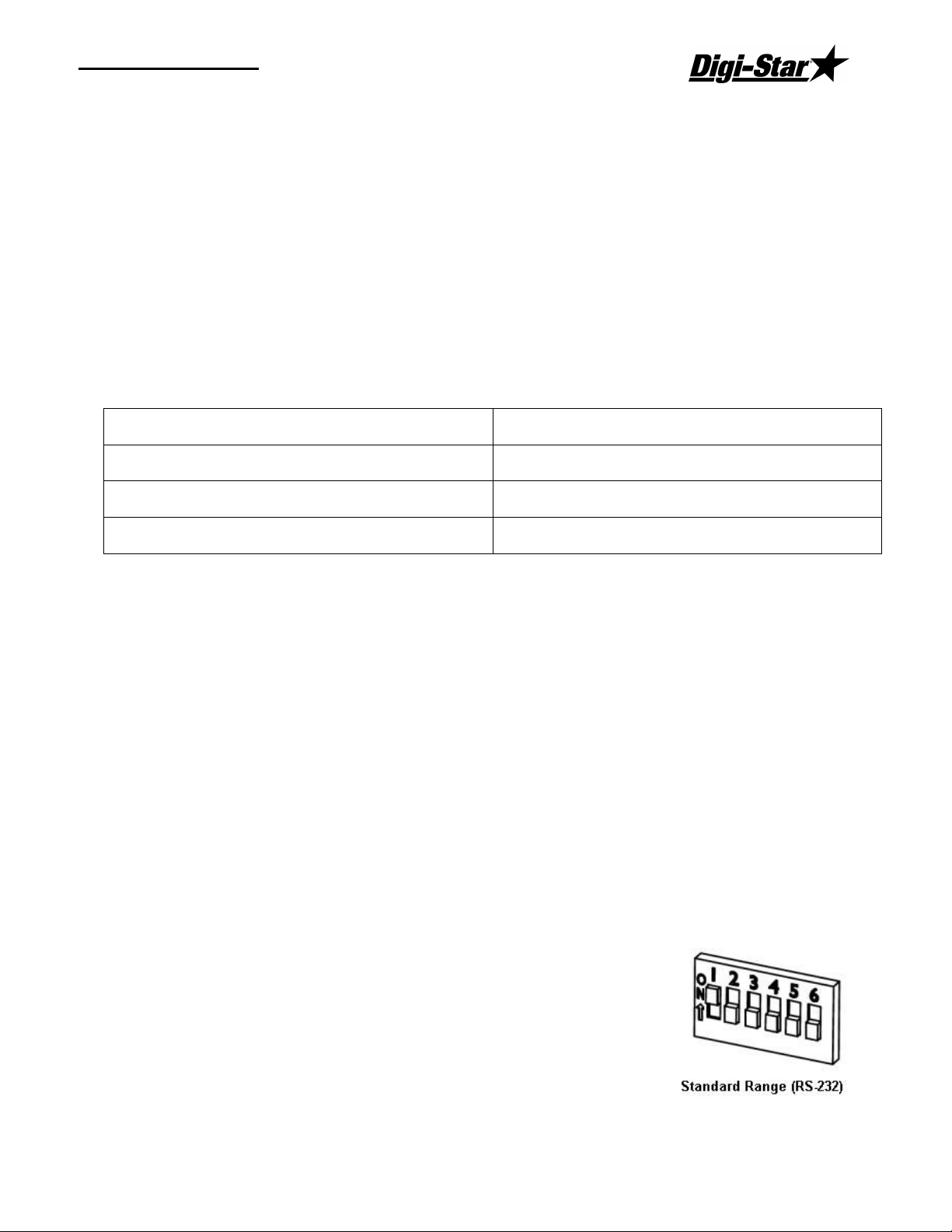
Standard Range Setup
When using the standard range kit, connect the DB9 serial connector to either a serial port on
the PC or use the USB to Serial adapter included and connect the
12VDC power supply to the cable. The base radio is shipped from
Digi-Star setup for standard range. The switch settings on the
radio are set to the picture to the right: Verify this if you are not
able to communicate with the base radio
D3664
3
RF DataLink
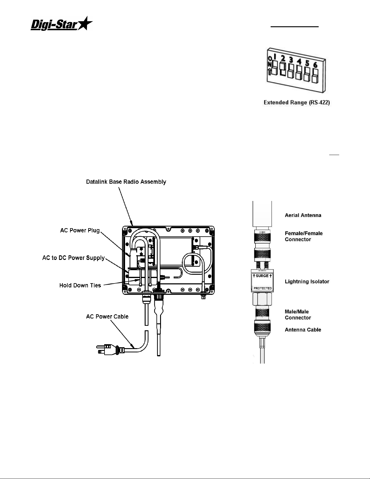
Extended Range Setup
If you are using the extended range radio kit (RS-422) you must
go to System, then Defaults, and select [Radio Settings]. Under
Base Radio Type, select [Extended Range Base Radio (RS-422).
RF Datalink will then pause while looking at the radio for the new
settings.
Next open the housing of the base radio. There is a bank of dip
switches on the right side,
Set switches as the picture on the right:
Install the AC/DC power transformer into the base radio box and run AC power into the unit
as shown. When attaching the female plug to the power cord, remove green ground wire
and attach either of the remaining two wires to either terminal. AC/DC adaptor is not
polarized.
Antenna Assembly
4
Operators Manual
USB Black Box Installation
Plug in the Black box into a USB port. Windows will
detect the Black box and at this point Insert the driver
CD. Follow the Windows prompts.
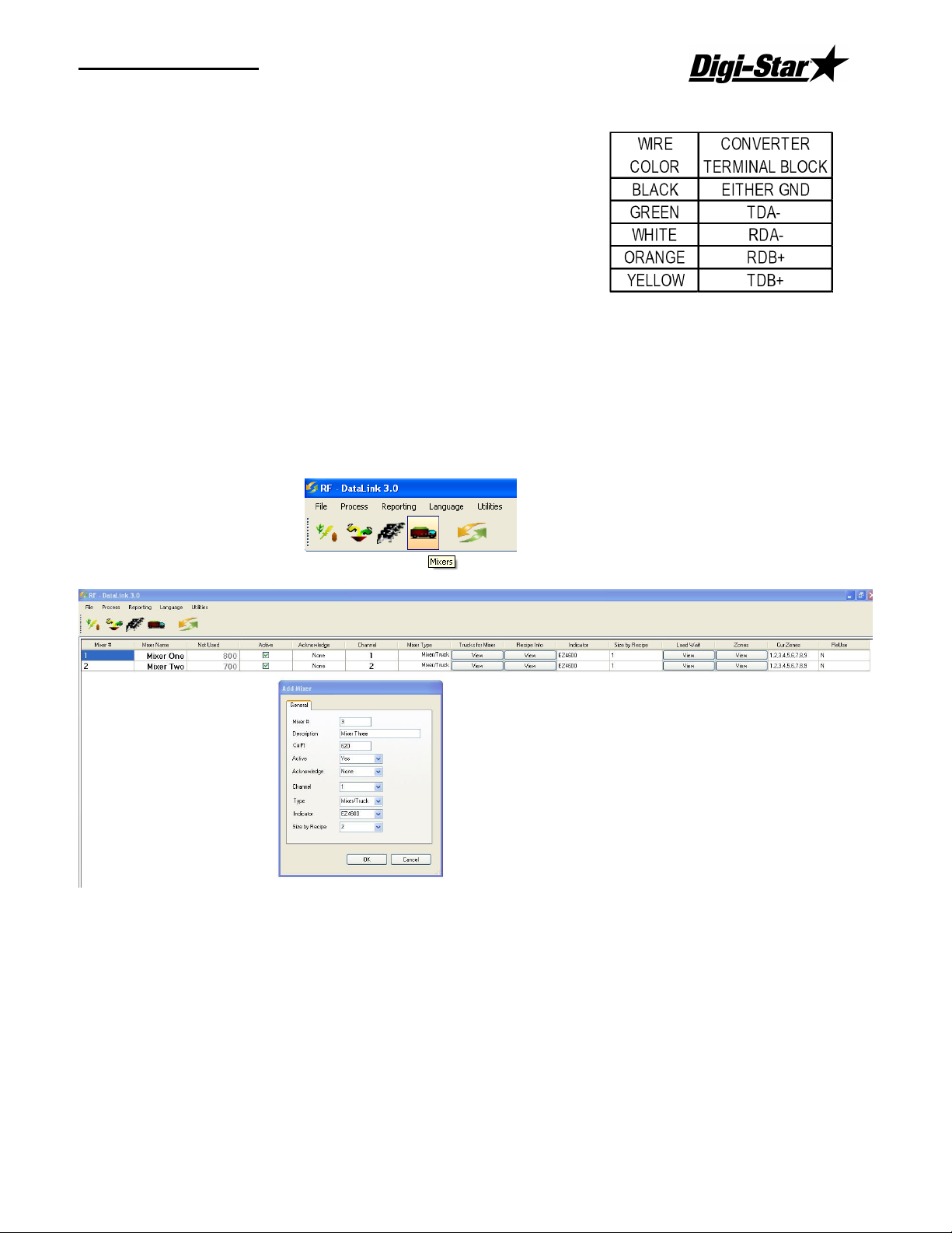
Open the end cover of the Black Box and install the wires
as follows:
Entering Mixer Data
Adding Mixers
To access the Mixers screen, select Mixers from the Menu. This will display the Mixers
screen. In a new installation, the Mixer screen will be blank.
Select the New button to add a new mixer. Enter the Mixer number 1-24 (this number
should match the Channel Number).
Mixer Number – a two-digit number to identify the Mixer.
Description – a detailed Mixer description. The first letter of this may be displayed on the
Process Screen.
Cu Ft – Enter the lbs/Kg per cubic foot/Meter.
Active - to signify that the Mixer is available for feeding, click on [Yes] in the Active box.
Clicking on [No] will make the Mixer un-available for loads or feeding.
D3664
5
 Loading...