


EZ400
Operators Manual
HELLO
Ft. Atkinson, Wisconsin USA
Panningen, The Netherlands
www.digi-star.com
D3655-US REV E |
February 09, 2010 |

EZ400 User’s Manual |
D3655-US Rev E |

|
Table of Contents |
|
TABLE OF CONTENTS |
|
|
TECHNICAL SPECIFICATIONS..................................................................... |
1 |
|
SAFETY DURING USE................................................................................... |
|
2 |
Cleaning....................................................................................................... |
|
2 |
Charging Battery and Welding..................................................................... |
2 |
|
INDICATOR OVERVIEW ................................................................................ |
|
3 |
OPERATION ................................................................................................... |
|
5 |
Turn on Indicator.......................................................................................... |
|
5 |
Zero Balance Indicator................................................................................. |
|
5 |
Tare and Net/Gross ..................................................................................... |
|
6 |
Store Data to DDL........................................................................................ |
|
8 |
Printing Gross Weights ................................................................................ |
|
8 |
Print Formats ............................................................................................... |
|
9 |
Changing Indicator ID Name & Clearing Accumulated Weight ................. |
10 |
|
Turning Off the Indicator ............................................................................ |
|
10 |
WEIGH METHODS ....................................................................................... |
|
11 |
General Weigh Method #1......................................................................... |
|
11 |
Slow Weigh Method #2 .............................................................................. |
|
11 |
Fast Weigh Method #3............................................................................... |
|
11 |
Lock-on Weigh Method #4......................................................................... |
|
11 |
WEIGHING ERRORS ................................................................................... |
|
12 |
Over-Capacity Limit (OVRCAP)...................................................................... |
12 |
|
Over Range (+RANGE).................................................................................. |
|
12 |
Under Range (-RANGE)................................................................................. |
|
12 |
Low Battery Indication (LO BAT)................................................................... |
12 |
|
RUN SELF TEST .......................................................................................... |
|
12 |
MENUS AND CALIBRATION |
........................................................................ |
13 |
Changing Options Using Long Form Setup ............................................... |
13 |
|
SHORT FORM CALIBRATION ..................................................................... |
17 |
|
Obtain Current Set-up and Calibration Number ........................................ |
17 |
|
Calibrating Scale For Maximum Accuracy................................................. |
18 |
|
Determining New Setup and Calibration Numbers.................................... |
18 |
|
Enter A New Setup And Calibration Number............................................. |
19 |
|
INSTALLATION............................................................................................. |
|
20 |
Indicator Mounting ..................................................................................... |
|
20 |
Optional Ram Mounting ............................................................................. |
|
20 |
Cable Connection ...................................................................................... |
|
21 |
Indicator Connection Diagram ................................................................... |
21 |
|
Bottom Panel Cable Connections.............................................................. |
21 |
|
Connect Load Cells to J-Box ..................................................................... |
22 |
|
Load Cell Direction..................................................................................... |
|
22 |
D3655-US Rev E |
EZ400 User’s Manual |
|

|
Table of Contents |
Indicator Calibration ................................................................................... |
22 |
OPTIONAL EQUIPMENT.............................................................................. |
23 |
Data Transfer Options................................................................................ |
23 |
Remote Indicators...................................................................................... |
23 |
TROUBLESHOOTING .................................................................................. |
24 |
All rights reserved. Reproduction of any part of this manual in any form whatsoever without Digi-Star’s express written permission is forbidden. The contents of this manual are subject to change without notice. All efforts have been made to assure the accuracy of the contents of this manual. However, should any errors be detected, Digi-Star would greatly appreciate being informed of them. The above notwithstanding, Digi-Star can assume no responsibility for errors in this manual or their consequence.
© Copyright! 2009 Digi-Star, Fort Atkinson (U.S.A.).
EZ400 User’s Manual |
D3655-US Rev E |

Technical Specifications
TECHNICAL SPECIFICATIONS
SIZE
7.33” long x 5.25” high x 3.38” wide (186mm x 133mm x 85mm)
WEIGHT
2 lbs (.91 Kg)
HELP MESSAGES
Context sensitive help messages in 10 languages
Long messages are scrolled
TRANSDUCER EXCITATION
DISPLAY RESOLUTION
.01, .02, .05, .1, .2, .5, 1, 2, 5, 10, 20, 50, 100
DISPLAY UPDATE RATE
Selectable: 1, 2, 3, 4 times/sec.
MAX. DISPLAY RESOLUTION
Adjustable to 40,000 counts max.
ZERO TRACKING
Selectable, On/Off
8 volts D.C. Nominal
Capable of driving eight 350 Ohms transducers Short circuit proof
ATC
Auto Temperature Compensation of the internal circuitry for high accuracy weighing measurements
TRANSDUCER SIGNAL
Compatible with transducers having full scale indicator transfer characteristics greater than 0.25 mv/v
“AUTO RANGE”
(Selectable) To increase display counts
at weight values of 300 and 600 display counts.
CONNECTOR
SPAN ACCURACY
±(.1% + .005%/ °F) or (.1% + 0.009% °C) full scale ± 1 output count
MOTION DETECTION
Selectable, On/Off
ZERO ACCURACY
(.005%/ °F.) or (0.009% °C) full scale ±1 output count for 0.5 mv/v transducer
ENVIRONMENTAL ENCLOSURE
IP65, IEC 529
WEIGH ALGORITHM
4 internally selectable digital filters to optimize performance
(General, Slow, Fast and Lock-on)
AMP plastic weather resistant circular |
NON-VOLATILE MEMORY |
|
connector. Gold contacts. |
EEPROM for balance |
|
POWER REQUIREMENTS |
OPERATING TEMP |
|
10.5 to 16.0 V.D.C. |
-29°C to 60°C |
-20°F to 140°F |
160 mA nominal with four 350Ω L.C.
SET UP AND CALIBRATION
Via front panel
GROSS RANGE
999,999 max.display
LOW BATTERY WARNING
Enabled at 10.5V nominal
POUND/KILOGRAM
Selectable
DISPLAY
STD EZ 6 Digit LCD 1.0. high
D3655-US Rev E |
EZ400 User’s Manual |
1 |
Safety During Use
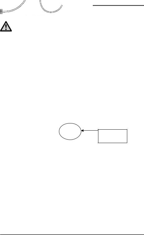
SAFETY DURING USE
Caution
Cleaning
Do not use running water (high pressure cleaners, hoses) to clean the indicator.
Charging Battery and Welding
Disconnect all cables from the weighing indicator before charging the battery or welding on the machine. If cables are left connected, the weighing indicator and connected load cells could be damaged.
Scale Indicator
Disconnect all cords
2 |
EZ400 User’s Manual |
D3655-US Rev E |

Indicator Overview
INDICATOR OVERVIEW
5
1 |
2 |
3 |
4 |
Note: See page 20 for installation instructions.
1 – press and hold for 3 seconds to zero balance indicator.
2 – temporary zero (Net Mode) (Standard EZ400).
-Optional: (EZ400 with serial port) temporary zero (Net Mode)
printer records to memory or prints displayed weight
3 – toggles between Net and Gross weights.
4 – turns indicator on/off. Press while on runs self test.
5Display Window – Displays current actions.
D3655-US Rev E |
EZ400 User’s Manual |
3 |

Indicator Overview
Bottom Panel
9 |
6 |
7 |
8 |
6 -Power Cord Connection – +12 VDC.
7 -Load Cell Connection – Connect cable from the J-Box.
8-Serial/J905 – Optional, to communicate with computer and other digital Input/Output devices.
9 - Remote Port – Optional, for remote display
Pin |
J905 Connector Signals |
1+5VDC
2Com #1 Out (Tx) - Computer
3 Com #1 In (Rx) - DDL & Computer
4 Com #2 Out (Tx) - Printer
5+12 VDC
6 Gnd – Available for any Com device
7 Com #2 In (Rx)
8Ground
4 |
EZ400 User’s Manual |
D3655-US Rev E |
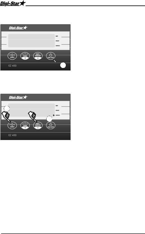
OPERATION
Turn on Indicator
H E L L O
 1
1
Zero Balance Indicator
1 0
0
Operation
1.Press  .
.
1.Press  for 3 seconds to zero balance indicator.
2.Flashing arrow points to gross next to the display window, indicator ready to weigh.
D3655-US Rev E |
EZ400 User’s Manual |
5 |
 Loading...