

Page 1
RD 400
Mirror Mount Remote
Installation Manual
Fort Atkinson, Wisconsin USA
Helden-Beringe, The Netherlands
www.digi-star.com
D3671-US Rev. A August 08, 2005
Page 2
RD 400
Features
The RD 400 Remote Display features a 14-segment display
capable of displaying the full alphanumeric output of the EZ
series indicators. The RD 400 provides a large 1-inch, 6 digit
display with fiber-optic backlighting. They are compatible with
EZ and EZ II series indicators.
When the EZ indicator is turned On, the remote also turns On
showing the full (14 segment) alphanumeric display of the EZ
indicator. The remote supports all of the annunciators used on
the EZ indicator. The alarm lamp on the front panel of the
remote turns On whenever the EZ indicator alarm lamp turns On.
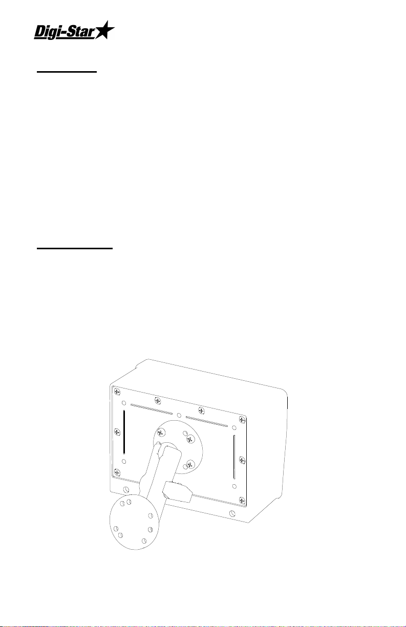
Installation
Attach the RD 400 using the RAM mount. Use the U-bolt mount
to clamp the mount onto your mirror bracket or secure the
mounting plate to a flat structure using the self-drilling screws
provided. P-clips and a grommet are also provided to assist in
routing the cable to the indicator.
Page 3

Installation Manual
If installation requires the cable to be removed from the Remote:
1. Remove the nine (9) screws to remove the rear panel of the
RD 400.
2. Loosen the five (5) screws on the terminal block at the
bottom edge of the circuit board. Pull each wire out of the
terminal block.
3. Loosen the plastic nut on the cable strain relief on the
bottom panel of the enclosure and pull the cable out of the
enclosure.
4. After routing the cable back to the RD 400, insert the cable
through the cable strain relief. Tighten strain relief nut
snugly using a wrench. Do not over-tighten.
RED
WHITE
BLACK
YELLOW
5. Place the wires in their correct locations as marked on the
circuit board and tighten the screws on the terminal blocks
securely.
Note: Blue and Orange wires are not used.
6. Connect the RD 400 cable to the “REMOTE” connector on
your EZ indicator and verify that the unit works properly. If
RD 400 does not work properly, check the terminal block
connections.
7. Install the rear cover using the nine (9) screws.
D3671
Page 4

RD 400
On EZ150, EZ210, EZ320 Indicators Only
The Original EZ series indicator (EZ150,EZ210, EZ320) can be
setup to work with either an old Model 20R or the newer RD
series remote display. When set incorrectly for a 20R, the RD
400 displays nonsense even when connected to an EZ indicator
that is working properly. Follow these six steps to change the
setup in the EZ indicator for the correct style of Remote Display:
8. Press and hold [NET/GROSS], then press and hold [ON].
9. Press [ON] several times until the message “PRESS
NET/GROSS FOR CALIBRATION - TARE FOR SETUP -
ON TO EXIT” scrolls across the display.
10. Press [TARE] to enter Section 3 of the “Long Form Setup”.
11. Press [ON] several times until the message “REMOTE” is
displayed.
12. Press [NET/GROSS] to select “EZ R” for both EZ Series and
RD Series Remote Displays.
13. Press [ON].
14. Press and hold [TARE], then press [ON] to exit setup.
15. The Remote now displays the same information as the EZ
indicator.
 Loading...