

Page 1
RD 2500
Installation Manual
Fort Atkinson, Wisconsin USA
Panningen, The Netherlands
www.digi-star.com
D3907-US Rev. B October 1, 2012
Page 2
RD 2500
Features
The RD 2500 Remote Display features a 14-segment display
capable of displaying the full alphanumeric output of the EZ
series indicators. The RD 2500 provides a large 1.7-inch, 6 digit
display with backlighting. They are compatible EZ III, EZII and
original EZ I series indicators.
When the EZ indicator is turned on, the remote also turns on
showing the full (14 segment) alphanumeric display of the EZ
indicator. The remote supports all of the annunciators used on
the EZ III indicator. The alarm lamp on the front panel of the
remote turns on whenever the EZ indicator alarm lamp turns on.
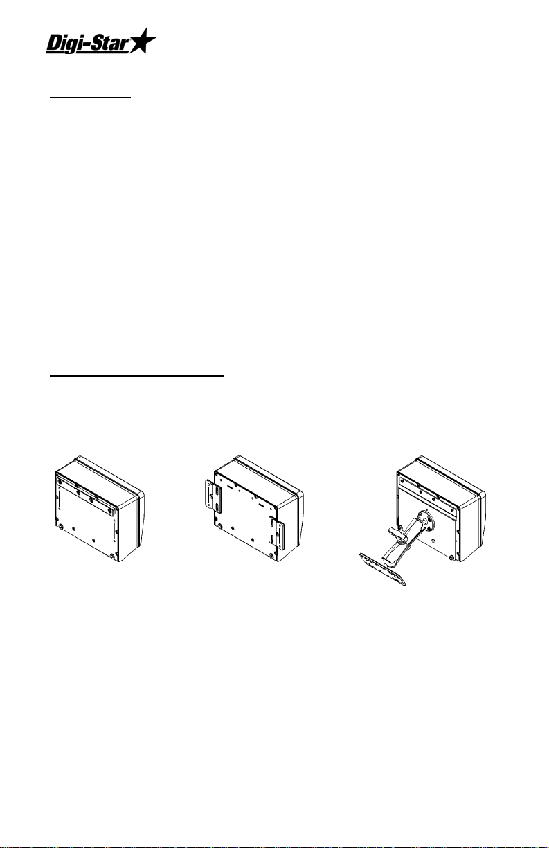
Indicator Mounting
Rail Mounting
Included
Wing Mount
Optional
RAM Mount
Optional
Page 3

Installation Manual
To Remove and Replace the Cable from the RD 2500:
1. Remove the ten (10) screws to remove the rear panel of the
RD 2500.
2. Loosen the five (5) screws on the terminal block at the
bottom edge of the circuit board. Pull each wire out of the
terminal block.
3. Loosen the plastic nut on the cable strain relief on the
bottom panel of the enclosure and pull the cable out of the
enclosure.
4. After routing the cable back to the RD 2500, insert the cable
through the cable strain relief. Tighten strain relief nut
snugly using a wrench. Do not over-tighten.
5. Place the wires in their correct locations as marked on the
circuit board and tighten the screws on the terminal blocks
securely.
6. Connect the RD 2500 cable to the “REMOTE” connector on
your EZ indicator and verify that the unit works properly. If
RD 2500 does not work properly, check the terminal block
connections.
7. Install the rear cover using the ten (10) screws.
D3907-US
Page 4

RD 2500
T/R Option
The RD2500 can be equipped with a T/R Radio Control feature.
This option allows the operator to “Advance Ingredient” or “Tare”
the indicator using a hand held remote control.
RS232 Communication
The RD2500 can be equipped to communicate via RS232
instead of the default remote communications method.
RS232 Jumper Configurations
JP4 open JP5 installed
9600 Baud
1200 Baud
JP3 open
JP3 installed
RS232 Terminal Block Connections:
1 Red/Orange 12V DC
2 White No Connection
3 Green No Connection
4 Yellow Data
5 Black/Blue Gnd
NOTE: Wire colors for RS232 may not match PCB labeling
Default Remote Communication
Default Jumper Configurations
JP4 installed JP5 open
Default Terminal Block Connections:
1 Red/Orange 12V DC
2 White Remote Zero
3 Green Segment
4 Yellow Clock
5 Black/Blue Gnd
Page 5

Installation Manual
D3907-US
 Loading...