

Page 1

John Deere
750/1560/1590-20 ft
Grain Drill
Scale System
Instructions
And
Repair Parts
Ft. Atkinson, Wisconsin USA
Panningen, The Netherlands
www.digi-star.com
D3858-US-Rev A August 26, 2011
Page 2
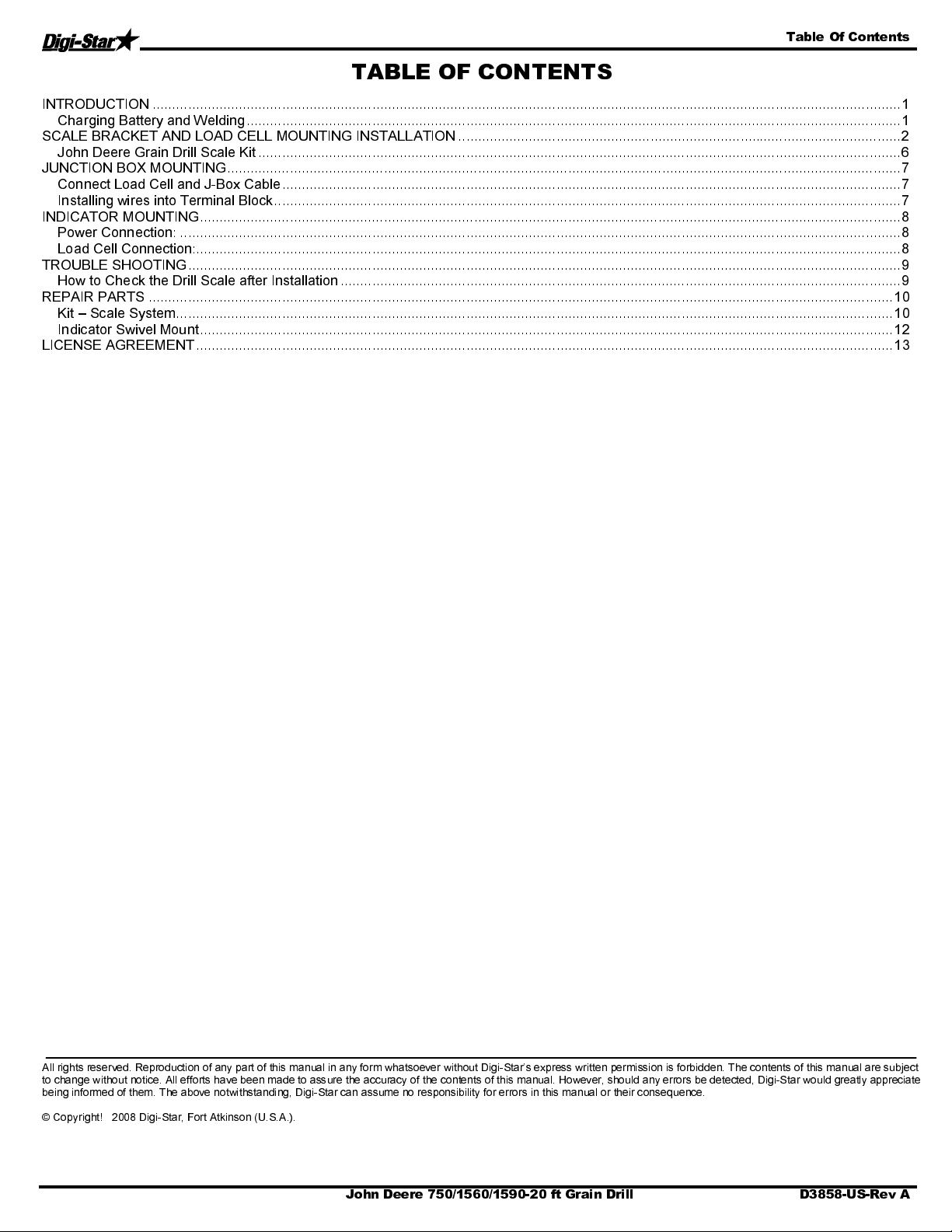
Table Of Contents
TABLE OF CONTENTS
INTRODUCTION ............................................................................................................................................................................................... 1
Charging Battery and Welding ....................................................................................................................................................................... 1
SCALE BRACKET AND LOAD CELL MOUNTING INSTALLATION ................................................................................................................. 2
John Deere Grain Drill Scale Kit .................................................................................................................................................................... 6
JUNCTION BOX MOUNTING ............................................................................................................................................................................ 7
Connect Load Cell and J-Box Cable .............................................................................................................................................................. 7
Installing wires into Terminal Block ................................................................................................................................................................ 7
INDICATOR MOUNTING ................................................................................................................................................................................... 8
Power Connection: ........................................................................................................................................................................................ 8
Load Cell Connection:.................................................................................................................................................................................... 8
TROUBLE SHOOTING ...................................................................................................................................................................................... 9
How to Check the Drill Scale after Installation ............................................................................................................................................... 9
REPAIR PARTS .............................................................................................................................................................................................. 10
Kit – Scale System ....................................................................................................................................................................................... 10
Indicator Swivel Mount ................................................................................................................................................................................. 12
LICENSE AGREEMENT .................................................................................................................................................................................. 13
All rights reserved. Reproduction of any part of this manual in any form whatsoever without Digi-Star’s express written permission is forbidden. The contents of this manual are subject
to change without notice. All efforts hav e been made to assure the accuracy of the contents of this manual. However, should any errors be detected, Digi-Star would greatly appreciate
being informed of them. The above notwithstanding, Digi-Star can assume no responsibility for errors in t his manual or their consequence.
© Copyright! 2008 Digi-Star, Fort Atkinson (U.S.A.).
John Deere 750/1560/1590-20 ft Grain Drill D3858-US-Rev A
Page 3

Introduction
p
INTRODUCTION
Congratulations on the purchase of your new Digi-Star Grain Drill Scale System. This scale system is
specifically designed to weigh the seed hopper on a John Deere 750/1560/1590-20 ft Grain Drill. The scale kit
can be used to record and monitor seed weight going into or out of the seed hopper.
This scale system is covered by the following US patents: 6,732,667; 7,059,258; 7,273,017; 7,357,087;
7,448,335; 7,523,710; 12/427,915; 6,572,257; and 7,454,304. The single-use license is included with this
document (see page 13).
This
SAFETY ALERT SYMBOL
symbol, be alert to the possibility of
NEVER OPERATE WITHOUT ALL COVERS, SHIELDS AND GUARDS IN PLACE. KEEP
HANDS, FEET AND CLOTHING AWAY FROM MOVING PARTS. FAILURE TO HEED MAY RESULT IN
SERIOUS PERSONAL INJURY OR DEATH.
Some covers and guards have been removed for illustrative/photographic purposes only in this manual.
For information on ordering repair parts, refer to Parts Section in this book.
This supersedes all previous published instructions.
indicates important safety messages in the manual. When you see this
PERSONAL INJURY
and carefully read the message that follows.
Important!
Charging Battery and Welding
Disconnect all cables from the weighing indicator before charging the battery or welding on the machine. If
cables are left connected, the weighing indicator and connected load cells could be damaged.
Important:
Do not weld near indicator, load cells or cables; remove from area to be welded. Place ground
close to area to be welded to prevent current from passing through electronic parts.
Scale Indicator
Remote Indicator
O
tional
Disconnect
all cords
J-Box
D3858-US-Rev A John Deere 750/1560/1590-20 ft Grain Drill 1
Page 4
Scale Bracket and Load Cell Mounting Installa tion
SCALE BRACKET AND LOAD CELL MOUNTING INSTALLATION
1. Remove the cat walk and drive chain off of both the ten foot seed bins.
2. On the left side of the seed bin, loosen the four bolts that hold the seed bin to the frame. DO NOT
remove bolts. Repeat the process on the right side.
3. Remove the bolts on the middle of the two seed boxes. The access hole will need to be cut in order to
access the back bolts.
Access Hole
4. On the inner frame on the left and right sides (that runs under the seed bin) place a jack between th e
frame and seed bin. Lift the middle of both seed bins up about 2-3”. Ins tall the middle bracket. Do not
tighten bolts.
Important:
The lifting chains, bucket attachments, loader/skid steer or winch must be capable of lifting
and controlling 1000 lbs.
Method of lifting
both sides of the
middle bin
2 John Deere 750/1560/1590-20 ft Grain Drill D3858-US-Rev A
Page 5
Scale Bracket and Load Cell Mounting Installation
5. Install the front and back middle load cells with the 2-1/4” clevis pins. The load cell’s arrow must be
pointed up (located on the end of the load cell). Two of the load cells are marked with short cords for
the center of the drill.
6. Next, install the rear middle bracket. Let the seed bin down to about 1”. Use the 2-1/2” x 3/8” clevis pin
to hold the weigh-bar in place. The pin should be in the middle of the 1/2” hole.
7. Install the front middle bracket. Install the 2-1/2 x 3/8 clevis pin the same as the rear bracket. Leave all
bolts loose.
D3858-US-Rev A John Deere 750/1560/1590-20 ft Grain Drill
3
Page 6

Scale Bracket and Load Cell Mounting Installation
8. On the left side, remove the bolts that hold the seed bin to the frame.
9. Lift the seed bin up about 2-1/2” on the left side.
The hopper can be lifted
by wrapping a nylon strap
or chain around the
hopper end. (Left side of
hopper shown.)
10. Install the middle bracket under the seed bin (do not tighten bolts yet). See the diagram of the John
Deere Grain Drill Scale Kit.
11. Install the front and back load cell with the 2-1/4” x 3/8” pins. Make sure the load cell arrow sticker is
pointed up.
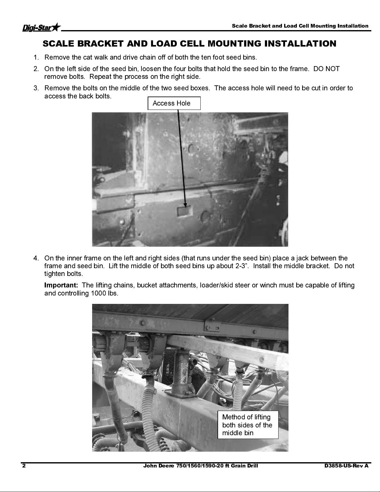
12. Let the seed bin down to about 1” and slide the rear bracket on. Use the 5/8” x 8” bolts in the front 2
holes. Use the 2-1/2” x 3/8” clevis pin to hold the load cell in place. Make sure the pin is in the middle
of the 1/2” hole. Note: The rear step grip is installed between the rear bracket and the step bracket
already on the grain drill. Do not tighten the bolts.
13. Install the front bracket with the bolts left from the rear bracket. Use the 2-1/2” x 3/8” clevis pin to hold
the load cell in place. Make sure the pin is in the middle of the 1/2” hole.
14. Make sure the middle, front and rear brackets are straight with each other.
15. Remove the bolts on the right side that hold the seed bin to the frame.
16. Repeat steps 9 to 14 on the right side of the drill.
4
John Deere 750/1560/1590-20 ft Grain Drill D3858-US-Rev A
Page 7

Scale Bracket and Load Cell Mounting Installation
17. When both sides are done, the brackets should stand straight; neither should lean. Tighten the bolts on
all brackets in the following order:
st
: Tighten the middle bracket
1
nd
: Tighten the rear bracket
2
rd
3
: Tighten the front bracket
18. Reinstall catwalk. Trim catwalk so that it does not interfere with middle bin support.
Trimming the catwalk
19. Bolt the readout in the cab with the bracket or mount the bracket on a stand in the front of the lift
cylinder.
20. Install power cord to a 12 volt negative ground battery (white or red is positive, black is negative).
Install the J-box on the seed bin in the middle of the drill
21. Route the load cell cords so it will not be bounced or pinched by anything (see Mount Junction Box
instructions).
22. Lengthen the drive chain with provided chain links. DO NOT TIGHTEN CHAIN. Leave the chain loose
enough so it is not pulling down on the seed bin.
D3858-US-Rev A John Deere 750/1560/1590-20 ft Grain Drill
5
Page 8

Scale Bracket and Load Cell Mounting Installation
John Deere Grain Drill Scale Kit
6
John Deere 750/1560/1590-20 ft Grain Drill D3858-US-Rev A
Page 9

Junction Box Mounting
JUNCTION BO X MOU NTIN G
The junction box is water resistant, not water-proof. It should be mounted to avoid submersion during wet
weather and to avoid physical abuse. Install the junction box on the front middle of the drill, by removing the
double sided tape backing and apply to cleaned planter surface.
Connect Load Cell and J-Box Cable
1. Route front and rear load cell cables to J-
box location. Make sure they are not
bound or pinched. Cable tie (customer
provided) load cell cables in place.
2. Insert load cell and J-box cables through
each of the water-tight strain-reliefs.
3. Remove each terminal block from the J-
box.
4. Connect wires of the same color to the
same terminal block. See instructions
below.
5. Install terminal block into the J-box as
shown (location not important).
6. Tighten nuts on the water-tig ht strain-
reliefs.
7. Assure that gasket is properly installed in
the cover.
8. Attach cover using 4 screws (provided).
Installing wires into Terminal Block
1. Open levers 90º to locked position.
2. Insert individual wires into terminal.
3. Close lever.
4. Tug wire to assure solid connection.
Note: Wire strip length is 7/16” (11mm).
406232 J-Box Lever Nut 4Pt (Planter)
141837 Cable - 30Ft J-Box
406074 Cable - 45Ft J-Box
403335 Cable - Power 17Ft 2-Wire
406073 Cable - Power 36Ft 2-Wire
406072 Cable - Power 6Ft 2-Wire
824316 Cable - 15FT-J-Box
145096 Cable - 70FT-J-Box
406276 Cable – Power 65FT 2-Wire
D3858-US-Rev A John Deere 750/1560/1590-20 ft Grain Drill 7
Page 10

Indicator Mounting
r
W
INDICATOR MOUNTING
The scale indicator can be mounted in the tractor cab or on the drill with swivel mounting pack (406081). Two
cables must be connected to the indicator bottom panel, J-Box and power cables. Refer to Indicator Manual
D3831-US for details of indicator mounting options and connection of power cord.
PLANTER MOUNTING
1. Bolt the readout in the cab with the bracket, or mount the bracket in the front of the lift cylinder.
2. Install power cord to a 12-volt negative ground battery.
3. Route J-box cable to indicator and install to indicator bottom panel.
4. Program indicator with set-up #145022 and calibration #21000 (see Indicator Manual)
INDICATOR MOUNTINGS
TRACTOR CAB MOUNTING
Power Connection:
The power cable should be connected directly to a vehicle battery or regulated power supply. The scale end of
the power cable is attached to the J901 connector located on the bottom panel of the indicator.
Connect the RED wire from the power cable to +12 VDC and the BLACK wire to GROUND. The indicator is
fused internally at 4 amps.
Power Cable Connections:
Wire colo
Red
Black
ire Function
Battery (+12 VDC)
GROUND
Load Cell Connection:
The indicator is designed to operate with strain gage load cells. The indicator will normally be supplied with a
“J-BOX” cable going between the scale and the load cell junction box. Extension kits
are available from your
dealer in various lengths.
Load Cell Wire Digi-Star Function
1 RED +EX
2 GREEN -SIG
3 WHITE +SIG
4 BLACK -EX
5 CLEAR SHIELD
8 John Deere 750/1560/1590-20 ft Grain Drill D3858-US-Rev A
Page 11

Trouble Shooting
TROUBLE SHOOTING
How to Check the Drill Scale after Installation
For the first test, lift the drill all the way up, to a level area. Put 200-250 pounds of weight on the right side,
then compare it to the left. Both sides should be within four to six pounds of each other.
•
If the weight is not within the four to six pound range, the drive chain might be too tight or the clutch is
binding. Loosen the chain and check the weight again.
•
If loosening the chain does not fix the problem, you must remove the clutch arm, and then check the
weight on both sides.
properly.
The second test is to lift the drill to a level area and zero the scale. Lift the drill up and down two to three times,
checking to see if the scale zeros out. Each time the scale is in the up position, it should be within four to six
pounds. If not, remove the clutch arm and repeat the test. If this solves the weigh problem, the clutch is
binding or it needs lubrication.
properly.
If further assistance is necessary, please call Digi-Star, LLC at 920-563-9700.
NOTE
NOTE
: The clutch arm needs to be reattached in order for the clutch to work
: The clutch arm needs to be reattached in order for the clutch to work
D3858-US-Rev A John Deere 750/1560/1590-20 ft Grain Drill 9
Page 12

Repair Parts
REPAIR PARTS
Kit – Scale System
10 John Deere 750/1560/1590-20 ft Grain Drill D3858-US-Rev A
Page 13

Repair Parts
KEY QTY. PART NO. DESCRIPTION
1 1 405874 Weld – Middle Support (JD750MB20)
2 1 405760 Weld – Rear Brkt LH (JD750-15’)
3 1 405761 Weld – Rear Brkt RH (JD750-15’)
4 1 405762 Weld – Front Brkt LH (JD750-15’)
5 1 405763 Weld – Front Brkt RH (JD750-15’)
6 2 405764 Weld – Middle Brkt (JD750-15’)
7 1 405851 Weld – Front Middle Supt (JD1590-20’)
8 1 405846 Weld – Rear Middle Supt (JD1590-20’)
9 1 405848 Plate-8 Hole Mnt Rear (JD1590-20’)
10 1 405847 Angle-4 Hole x 6” (JD1590-20’)
11 10 405854 Scr 1/2-13 x 2-1/4 HHCS ZP Grd 5
12 2 405864 Scr 5/8-11 x 2-1/2 HHCS ZP Grd 5
13 12 405863 Scr 5/8-11 x 8-1/2 HHCS ZP Grd 5
14 2 405866 Scr 5/8-11 x 10 HHCS ZP Grd 5
15 12 171610 Wash 3/8 Flat Narrow ZP
16 10 405053 Wash 1/2 Flat Wide ZP
17 28 405858 Wash 5/8 Flat Wide ZP
18 10 406085 Nut 1/2-13 Ser Flange ZP
19 16 406070 Nut 5/8-11 Top-Lock Flange ZP
20 12 405859 Pin-Cotter 5/32 x 1.5 ZP
21 6 405860 Pin-Clevis 3/8 x 2.25 ZP
22 6 405861 Pin-Clevis 3/8 x 2.5 ZP
23 6 405862 Link-Offset #40
24 2 405865 Spacer-1.5 (JD1590-20’)
25 1 405878 Paint-JD Green Aerosol
26 2 400373 Cell-1.5 DB-11FT
27 4 400400 Cell-1.5 DB-16FT
28 1 406233 Assy J-Box 6PT (Planter)
29 1 141837 Cable-30FT J-Box
30 1 406072 Cable-Power 6FT 2-Wire
31 1 405612 GT400 Indicator
D3858-US-Rev A John Deere 750/1560/1590-20 ft Grain Drill 11
Page 14
Repair Parts
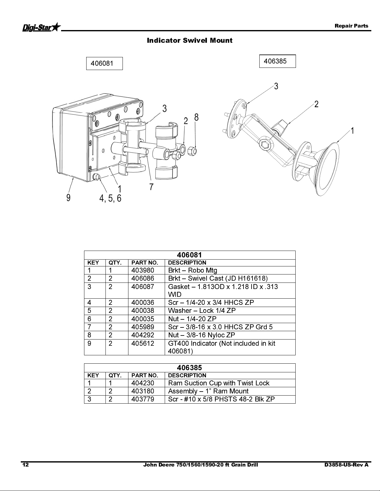
Indicator Swivel Mount
406081
406385
406081
KEY QTY. PART NO. DESCRIPTION
1 1 403980 Brkt – Robo Mtg
2 2 406086 Brkt – Swivel Cast (JD H161618)
3 2 406087 Gasket – 1.813OD x 1.218 ID x .313
WID
4 2 400036 Scr – 1/4-20 x 3/4 HHCS ZP
5 2 400038 Washer – Lock 1/4 ZP
6 2 400035 Nut – 1/4-20 ZP
7 2 405989 Scr – 3/8-16 x 3.0 HHCS ZP Grd 5
8 2 404292 Nut – 3/8-16 Nyloc ZP
9 2 405612 GT400 Indicator (Not included in kit
406081)
406385
KEY QTY. PART NO. DESCRIPTION
1 1 404230 Ram Suction Cup with Twist Lock
2 2 403180 Assembly – 1” Ram Mount
3 2 403779 Scr - #10 x 5/8 PHSTS 48-2 Blk ZP
12 John Deere 750/1560/1590-20 ft Grain Drill D3858-US-Rev A
Page 15

License Agreement
LICENSE AGREEMENT
IMPORTANT NOTICE: Acceptance and use of the enclosed electronic scale products (hereinafter referred to as
“Purchased Product”) constitu tes your agreement to the following terms and condi tions. Please carefully read the
following terms and conditions before using or reselling the Purchased Product.
1. Limited License
(“Owner”) is the owner of the following U.S. Patents related to grain
drills: 6,732,667, 7,059,258, 7,273,017, 7,357,087, 7,448,335,
7,523,710 and any other patents which result from continuation
applications thereof (“Patents”). Owner hereby grants to the customer
(“Customer”) a non-exclusive, non-transferable, revocable, limited
license to use the technology described in the Patents to use the
Purchased Product to assemble a seed planter product covered by the
Patents (“Licensed Product”), and to sell and offer for sale one (1) unit
of the Licensed Product in accordance with the terms and condition s set
forth herein. Alternatively, Customer may resell the Purchased Product
to another entity for the purpose of tha t entity assembling one (1) unit o f
a Licensed Product under a permitted sublicense from the Customer
with the same terms as this Agreement. If Customer woul d like to
assemble, use, sell or offer for sale more than one (1) Licensed Product,
or resell more than one (1) Purchased Product, Customer understands
and agrees that it m ust pur chase a nother Purchase d Product from Ow ner
or acquire a separate license by requesting and purchasing another unit
of the same SKU n umber tha t resul ted in this pur chase.
2. Acceptance of Terms and Conditions
authority to enter into this binding agreement. If Customer does not
accept the terms and conditions, Customer shall not use the Purchased
Product. Customer understands and agrees that if it uses the Purchased
Product as permitted herein, it will be deemed to have accepted these
terms and condi tions and t hey shall bec ome a bin ding agreement .
3. Limitations on Use
Product only as expressly authorized in this Agreement, and that any
use not expressly authorized in this Agreement is prohibited. Customer
agrees that it will not: (i) loan, rent, lease, assign, sublicense, distribute
or otherwise transfer its rights under this Agreement to a third party,
other than to resell the Purchased Product to anot her entity for the
purpose of that entity assembling one unit of a Licensed Product; (ii)
copy or reproduce the Licensed Product; or (iii) grant any sublicenses
other than to a n end user o f the Lice nsed Pr oduct, or to a nother entity for
the purpose of that entity assembling one unit of a Licensed Product.
Customer agrees to use reasonable efforts to prevent any unauthorized
use or copying of the Licensed Product and will notify Owner
immediately upon learning of any such unauthorized use or copying.
Customer’s obligations under this section shall survive any termination
of this Agreement or the license granted hereunder. Any unauthorized
use of the Licensed Product will result in, among other things, the
immediate termination of t his lice nse.
4.
Ownership of Proprietary Rights
Licensed Product is covered intellectual and/or proprietary rights, and
that all such intellectual and proprietary rights are owned by Owner.
Customer hereby acknowledges that it has no rights in the
foregoing except as expressly granted herein.
5. NO WARRANTY
the Purchased Product and Customer acknowledges and agrees
that Owner will not assume any product liability or any other
. Digi-Star, LLC, a Wisconsin limited l iability company
. Customer warrants that it has the
. Customer agrees that it will use the Licensed
. Customer acknowledges that the
. Customer agrees to fully test and evaluate
liability for the Purchased Product or the Licensed Product. The
Purchased Product is furnished to Customer “AS IS.”
otherwise provided by separate documentation
MAKES NO WARRANTIES, EITHER EXPRESS OR
IMPLIED, WITH RESPECT TO THE PURCHASED
PRODUCT. Customer agrees that Owner shall have no liability
resulting from Customer’s use of the Purchased Product for any
indirect damages including consequential, incidental or special
damages for loss of profit, good will or otherwise. Customer
shall indemnify and hold Owner harmless from any and all
losses, expenses, damages, costs or expenses of any kind,
including but not limited to reasonable attorneys’ fees, incurred
by Owner resulting from Customer’s use of the Purchased
Product. NO ORAL OR WRITTEN STATEMENTS MADE BY
OWNER OR ITS EMPLOYEES INCLUDING BUT NOT
LIMITED TO STATEMENTS REGARDING CAPACITY,
SUITABILITY FOR USE, OR PERFORMANCE OF THE
PURCHASED PRODUCT SHALL BE DEEMED A
WARRANTY OR REPRESENTATION BY OWNER FOR
ANY PURPOSE NOR GIVE RISE TO ANY LIABILITY OR
OBLIGATION OF OWNER.
6. Remedies for Violations
remedies available at law and in equity for violations of this
Agreement, including but not limited to the right to recover the
Licensed Product.
7. Fees
8. Entire Agreement
9. Severability
10. Governing Law
. In consideration for the rights granted under this
Agreement, Customer has paid a license fee that was included in
the amount invoiced to the Customer for the sale of the
Purchased Product.
contrary, this Agreement constitutes the entire agreement
between the parties regarding the subject matter hereof, and no
verbal or written prior statements or representations of any sort
made by any party shall be effective or valid for any purpose
whatsoever. This Agreement may be amended only upon the
mutual consent of all parties in writing.
. If any provision of this Agreement shall be held to
be invalid, illegal or unenforceable, the validity, legality and
enforceability of the remaining provisions shall not in any way
be affected or impaired thereby. The failure of any party to
enforce any provision of this Agreement shall not be considered
a waiver thereof, nor shall such failure prevent the future
enforcement of any such provision.
. This Agreement and the relationship between
the parties shall be governed in all respects by the laws of the
State of Wisconsin and the United States of America. The
parties consent to the jurisdiction and venue of the Wisconsin
and United States courts located in Wisconsin for resolution of
any dispute under to this Agreement.
.
Owner reserves the right to seek all
. Except as expressly stated herein to the
, OWNER
Except as
Use or sale of the Licensed Product or of Purchased Product shall bind Customer to all terms and
conditions herein without the necessity of signatures on this Agreement.
D3858-US-Rev A John Deere 750/1560/1590-20 ft Grain Drill 13
 Loading...