

Page 1

ICP 300
Magnetic Compatibility (EMC)
108/EC
when installed and used in accordance with the relevant
instructions.
Service and Technical Support
PLEASE CONTACT YOUR NEAREST DISTRIBUTOR
If unknown then fax: 44 (0) 1453 733322
© Copyright RDS Technology Ltd 2013
Document number
570: Issue 2.0 : 15.8.13
UK570200.DOC
User Guide
Electro-
This product complies with Council Directive 2004/
S/DC/500-10-
\
In-Cab Printer
Operation
1
Page 2

ICP 300 IN-CAB PRINTER
Contents
1. Introduction______________________________________3
2. Operation________________________________________3
2.1 Power-On Self-Test.............................................................................................4
2.2 Status LED..........................................................................................................4
2.3 Replacing the paper roll.....................................................................................5
2.4 Maintenance.......................................................................................................6
2.5 Service.................................................................................................................6
3. Installation - RDS Instruments _____________________7
3.1 Connection - RDS 'Wizard','G-Wiz', 'G-CAN', 'ISOCAN'.....................................7
3.2 Connection - RDS 'Pro-Series'...........................................................................8
3.3 Setup...................................................................................................................8
'Wizard' and 'G-Wiz'..............................................................................................8
Pro-Series, 'G-CAN' and 'ISOCAN'......................................................................8
4 Installation - Digi-Star Indicators___________________9
4.1 Verify Software Revision.....................................................................................9
4.2 Setup Keypad-based Scales.............................................................................9
4.3 Setup Basic Scales..........................................................................................10
4.4 Connecting the ICP300 Printer.......................................................................10
5. Parts List________________________________________12
6. Specific
ations 13
2
Page 3
1. Introduction
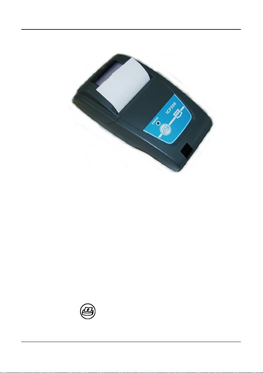
Figure 1
The RDS ICP 300 In-Cab printer is an ultra-compact thermal printer designed
for easy paper loading. It accepts 58mm wide rolls up to 44mm dia.
The printer is connected to and powered from the instrument via a custom
cable with RJ-12 connector, and operates with a supply voltage in the range
10-35V dc.
No maintenance is required, except to occasionally clean the rubber paper
roller to remove any dirt buildup.
2. Operation
ICP 300 IN-CAB PRINTER
When installed with a Wizard instrument the printer is normally powered on
as the vehicle is started.
When installed with a Pro-Series/Psi instrument the printer is powered on
when the instrument is switched on.
The status LED illuminates and the printer mechanism is reset.
Pressing the button advances the paper.
3
Page 4
ICP 300 IN-CAB PRINTER
2.1 Power-On Self-Test
Press and hold the button and then power up the instrument. The
printer will then print a self-test report.
The self-test procedure checks most of the printer functions except for the
serial interface
2.2 Status LED
If there is a problem with the printer, the status LED will indicate a fault
condition by a flashing sequence as follows.
LED Indication Condition Solution
On Normal Off No Power -
* * * Paper Out Fit new paper
** ** ** Print head too hot Allow head to cool
*** *** *** Power below 10V dc Check supply +V
4
Page 5
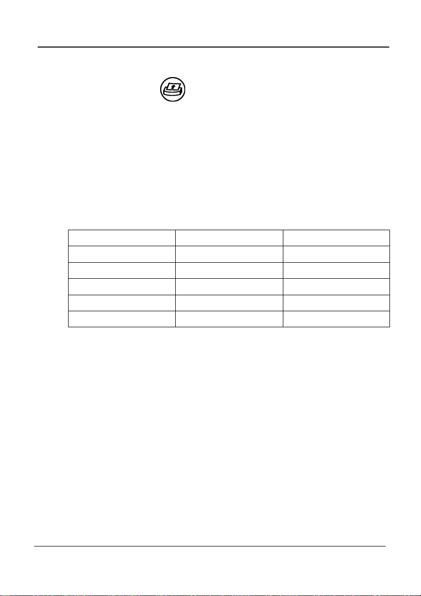
2.3 Replacing the paper roll
Pull the lever up until the lid is released. Do not use excessive force.
Figure 2: Unlock paper compartment
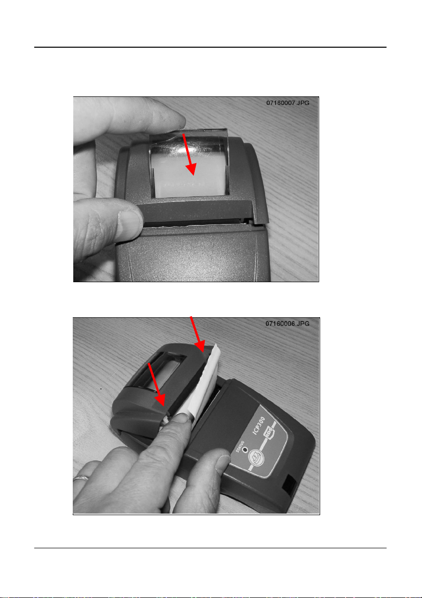
Replace the roll and press the lid at each side until it clicks shut.
Figure 3: Lock paper compartment
ICP 300 IN-CAB PRINTER
5
Page 6

ICP 300 IN-CAB PRINTER
2.4 Maintenance
Occasionally, it may be necessary to clean dust or foreign matter from the
paper compartment. Wipe the paper compartment clean using a dry soft
cloth only.
The rubber roller can be removed for cleaning if necessary. Push the roller
forwards at each end to disengage it from the slots (figure 4).
NOTE: DO NOT angle the roller too far with one end still engaged as this may break
DO NOT touch or attempt to clean the print head.
Figure 4: Remove paper roller
the moulding.
2.5 Service
There are no servicable parts. In the event of damage or failure, the printer is
replaceable only as a complete unit.
6
Page 7

ICP 300 IN-CAB PRINTER
3. Installation - RDS Instruments
3.1 Connection - RDS 'Wizard','G-Wiz', 'G-CAN', 'ISOCAN'
(Printer cable Pt No. S/CB/167-4-005)
These instruments all utilise variants of the 'Terminator' junction box for
RS232 serial connections.
A 4-way IDC header is the standard connection for the ICP300 printer (fig. 5).
IDC Connections:
Pin Wire Colour Function
1 White +V Supply (10-35V)
2 Red CST (from printer
3 Green Rx (To printer)
4 Blue ground
1. Plug the printer cable (RJ-12) into the back of the printer.
2. Plug the printer cable in the terminal box as shown (using a cable-tie for
strain relief).
Figure 5
7
Page 8

ICP 300 IN-CAB PRINTER
3.2 Connection - RDS 'Pro-Series'
(Printer cable Pt No. S/CB/167-4-006)
Depending on the product variant, connect the 9-way 'D' plug into either the
top port or the bottom port on the back of the head unit.
A connector clamp is supplied to secure the plug in position.
Product Port Used
Loadmaster 8000i / 8000iX TOP
Ceres 8000i BOTTOM
PS Artemis BOTTOM
3.3 Setup
For all RDS instruments, the default protocol settings for printer output are as
follows,
Baud Rate 4800
Data Bits 8
Stop Bits 1
Parity None
Handshake RTS
NOTE: The printer is not configurable.
'Wizard' and 'G-Wiz'
Depending on the product variant, there may be an 'ON/OFF' setting in the
Setup menu to enable printer output.
Please refer to the calibration manual for your instrument to configure printer
output.
Pro-Series, 'G-CAN' and 'ISOCAN'
These instruments have 2 serial ports configurable for devices other than
printers, such as GPS, barcode scanners etc. Depending on the software
default settings for a particular product variant, it may be necessary to reconfigure the port setting in the Setup menu to enable printer output.
Please refer to the calibration manual for your instrument to configure printer
output.
8
Page 9

ICP 300 IN-CAB PRINTER
4 Installation - Digi-Star Indicators
(Printer cable Pt No. S/CB/167-4-007)
Your Digi-Star scale indicator needs to be configured to run with your new
ICP300 printer. Version 8.0 or newer software is required for the printer to
function correctly. A RS232 serial port needs to be present on your scale
indicator, which is normally labeled as “Serial”, “J904”, or “J905” based on
model.
4.1 Verify Software Revision
1. Turn on the scale and wait for normal operation.
2. Press “ON” to start the self-test sequence (EZ2500V and EZ400/ GT400
models press “NET/GROSS” then “ON/OFF” to start).
3. Watch the self-test sequence on the screen. The words “PRG ID” will be
displayed, followed by the software version code. Press “ON” to pause the
test if needed. This software code must be “8.0” or larger to continue;
contact Digi-Star or an authorized service center to upgrade to newer
software if required.
4. Press any other key to cancel the self-test.
4.2 Setup Keypad-based Scales
1. Press 271 on keypad then “Select”.
2. Press “Select” again until “8N1” is displayed.
3. Press “ON” to save.
4. Press 275 on keypad then “Select”.
5. Press “Select” again until “4800” is displayed.
6. Press “ON” to save.
7. Turn off indicator, then turn back on.
9
Page 10

ICP 300 IN-CAB PRINTER
Battery
Battery
Frame
Blue Brown
Wires to Indicator
4.3 Setup Basic Scales
1. Hold “NET/GROSS” then press “ON”.
2. Press “NET/GROSS” or “Select” two times to access MENU 2.
3. Repeatedly press “ON” until “C1-1PA” is briefly displayed.
4. Press “NET/GROSS” or “Select” again until “8N1” is displayed.
5. Press “ON” until “C1-1BD” is briefly displayed.
6. Press “NET/GROSS” or “Select” again until “4800” is displayed.
7. Repeatedly press “ON” until indicator is no longer in MENU settings (normal
operation).
8. Turn off indicator, then turn back on.
4.4 Connecting the ICP300 Printer
Important: Verify scale indicator, printer, and other power source
connections prior to installation on 24 volt tractors and equipment. All
ground connections must be at 0V frame ground potential.
For 24 volt power systems, the scale indicator power connections must come
from the 12 volt battery connected to the frame ground as shown below.
Incorrect wiring may result in damage to your printer, cabling, or scale
indicator.
24V System - Correct Wiring
10
Ground
Page 11

ICP 300 IN-CAB PRINTER
Battery
Battery
Frame
Blue Brown
Wires to Indicator
24V System - Incorrect Wiring
1. Install paper into printer.
2. Connect power cable; Brown wire to +10 to +35V, Blue wire to – / Frame
Ground.
3. Connect black AMP connector to the serial port of scale indicator
(“Serial”, “J904”, or “J905”).
4. Connect phone style connector to base of printer.
5. Press “PRINT” key on scale indicator several times to verify correct print out.
Refer to Scale Indicator Operation Manual, D3739 rev D Technical Manual, or
D3648 Serial Commands Manual to set and select different print formats as
needed.
Ground
11
Page 12

ICP 300 IN-CAB PRINTER
5. Parts List
Kit Ref: Part No Description Qty
P/ICP300/WIZ
P/ICP300/PS
P/ICP300/DS
plus:
P/ICP300/WIZ
P/ICP300/PS
S/HU/167-4-001 ICP 300 Printer 1
S/FSNR/940117 M6 x 16 Hex Set Screw 2
S/FSNR/406 M6 Nut 2
S/FSNR/940205 M6 Washer 2
S/CBL/TIE/001 Cable Tie 25
S/AC/167-3-030 Paper Roll 2
S/DC/500-10-570 Instruction Manual 1
S/CB/167-4-005 Printer Cable - Wizard 1
S/DC/500-10-013 Warranty Card - Industrial 1
S/DC/500-10-014 Warranty Card - Agricultural 1
S/DC/500-10-015 Warranty Registration card 1
S/CB/167-4-006 Printer Cable - Pro-Series/PSi 1
S/AC/268-1-078 9-way 'D' Connector Clamp 1
S/DC/500-10-013 Warranty Card - Industrial 1
S/DC/500-10-015 Warranty Registration card 1
S/CB/167-4-007 Printer Cable - Digi-Star 1 P/ICP300/DS
S/DC/500-10-014 Warranty Card - Agricultural 1
12
Page 13

6. Specifications
Printing
Printing System Direct Thermal line head
Characters per line 48
Character matrix 24 x 8
Horizontal dot pitch 0.125mm (200 dpi)
Vertical Dot pitch 0.125mm
Printing width 48mm
Max. print speed 10 lines per second
MTBF Approx. 10
Power
Voltage External 10 – 35 V dc
Operating Current From 1A @ 35V to 2.7A @ 10V
Standby 30 mA
Paper
Paper roll 58mm x 44mm dia
Paper specification TF50-KS-E2D (recommended)
I/O
Interface RS232C
Connector 6-way RJ-12 socket
Baud rate 4800
Parity None
Data Bits 8
Stop Bits 1
Handshake Hardware (CTS)
Buffer 5 Kbyte
Character set ASCII
Environmental
Operating 0°C to +50°C
Storage -20°C to +60°C
Dimensions 85.5mm x 150mm x 55mm (excluding bracket)
Weight 0.4 kg (excluding bracket)
ICP 300 IN-CAB PRINTER
7
lines (20°C, print ratio 25%)
13
Page 14

ICP 300 IN-CAB PRINTER
Issue 1: 17/7/07 Original issue
Issue 1.01: 11/8/08 Ref. p.3 Parts List
Issue 2.0: 15.8.13 General revision including Digi-Star variant
14
 Loading...