

Page 1
GT465
Operators Manual
H e l l
H e l l
H e l lH e l l
oooo
Ft. Atkinson, Wisconsin USA
Pannigen, The Netherlands
D3968-US Rev A
www.digi-star.com
November, 7 2013
Page 2

2 GT465 Operators Manual D3968 Rev A
Page 3

Table of Contents
GT465 FEATURES .....................................................................................................................................................4
CHARGING BATTERY OR WELDING ......................................................................................................................5
INDICATOR OVERVIEW ...........................................................................................................................................6
INDICATOR DISPLAY SCREENS .............................................................................................................................7
BOTTOM PANEL CONNECTIONS ............................................................................................................................7
SELECTING FIELDS AT GT465 INDICATOR ...........................................................................................................8
SELECTING ID'S AT GT465 INDICATOR .................................................................................................................9
VIRTUAL TERMINAL OVERVIEW .......................................................................................................................... 10
VIRTUAL TERMINAL DISPLAY SCREENS ........................................................................................................... 11
ACTIVE SCREEN .................................................................................................................................................... 12
DATA RECORD SCREEN ...................................................................................................................................... 13
FIELD SCREEN ....................................................................................................................................................... 14
ID SCREEN ............................................................................................................................................................. 15
Clearing The Indicator Memory Before Starting A Season .................................................................................. 16
Erase Grain Tracker™ Data Records .................................................................................................................. 16
Zero Accumulator Memory ................................................................................................................................... 17
DAILY DATA COLLECTION .................................................................................................................................... 18
Mid-Season Name Changes ................................................................................................................................ 18
Modify Field Names And ID ................................................................................................................................. 18
TRANSFER DATA ................................................................................................................................................... 19
To Store Data Records On A USB Flash Drive ................................................................................................... 20
To Store Field and IDs On A USB Flash Drive .................................................................................................... 20
Transfer Field And ID Data From USB To Indicator ............................................................................................ 21
Record Data (W/ AutoLog) ................................................................................................................................... 22
Record Data (Without AutoLog) ........................................................................................................................... 23
Recorded Data Preview ....................................................................................................................................... 24
Check Combine Yield Monitor ............................................................................................................................. 24
RE-CALIBRATING YOUR SCALE .......................................................................................................................... 25
Get Your Calibration Number ............................................................................................................................... 26
Enter New Calibration Number ............................................................................................................................ 26
OPTIONAL SETTINGS............................................................................................................................................ 27
Backlight Dimmer ................................................................................................................................................. 27
Unload Alarm ....................................................................................................................................................... 27
Change Time ........................................................................................................................................................ 28
Change Date ........................................................................................................................................................ 28
Preset Active Signal ............................................................................................................................................. 29
SETTING OPTIONS ................................................................................................................................................ 30
WEIGHING ERRORS .............................................................................................................................................. 35
HARNESSES and CONNECTIONS ........................................................................................................................ 35
INSTALLATION ....................................................................................................................................................... 36
CONNECT LOAD CELLS TO J-BOX ...................................................................................................................... 37
TROUBLESHOOTING............................................................................................................................................. 38
RPM Sensor Diagnostics ..................................................................................................................................... 38
Verify AutoLog Settings ....................................................................................................................................... 39
D3968 Rev A GT465 Operators Manual 3
Page 4

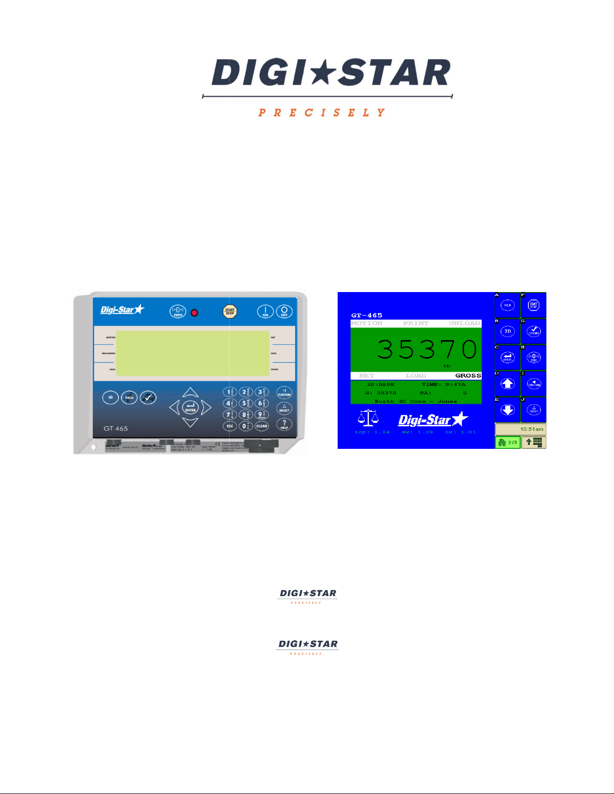
GT465 FEATURES
Weighing/ Data Center
The GT465 indicator serves as a weighing and data transfer center that can be connected to today’s ISOBUS Virtual
Terminals (VT). Weighing information is displayed on the virtual terminal and all data transfer takes place at the
GT465 indicator. Weight, date, time and additional notes are all stored automatically at the GT465 with AutoLog.
The GT465 also serves as a display for the combine operator to view while loading the cart. If issues arise with the
virtual terminal the system can be operated from the GT465.
Preset Active Signal
Preset Active Signal uses a combination of settings to program the 12 volt Alarm Out relay, with the ability to
enter a preset weight. With this programming control, the GT465 can be connected to a variety of accessories
such as external alarms, hydraulic solenoids, and other electronics. The preset weight is activated by AutoLog for
use of more hands free applications.
USB Port
USB flash drive has capacity to hold thousands of data records and allows easy data transfer to your office PC.
Records can be stored for an entire season in the indicator memory and transferred on one 256 Megabyte or
larger USB flash drive.
Grain Tracker™
Grain TrackerTM software provided with GT465 indicator (on the USB flash drive included) allows generation of a
variety of reports on your PC. Reports can be read by programs such as Microsoft ExcelTM, Adobe AcrobatTM and
Microsoft Internet ExplorerTM.
Memory Capacity – 13,000 Loads
Virtual Terminals
The GT465, when connected to the ISOBUS should be detected by the virtual terminal. If not, check all
connections and that the GT465 is powering up. If no issues are found, please contact the virtual terminal
manufacturer for more troubleshooting tips or terminal updates.
4 GT465 Operators Manual D3968 Rev A
Page 5
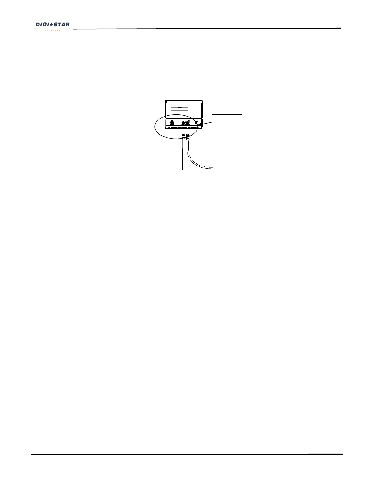
CHARGING BATTERY OR WELDING
Scale Indicator
Disconnect
all cords
Important: Disconnect all indicator leads before charging battery or welding.
Damage may occur to indicator and load cells.
D3968 Rev A GT465 Operators Manual 5
Page 6

1
2
3
4
5
6
7
8
9
10
11
2
3
4
5
6
7
8
12
13
14
15
1
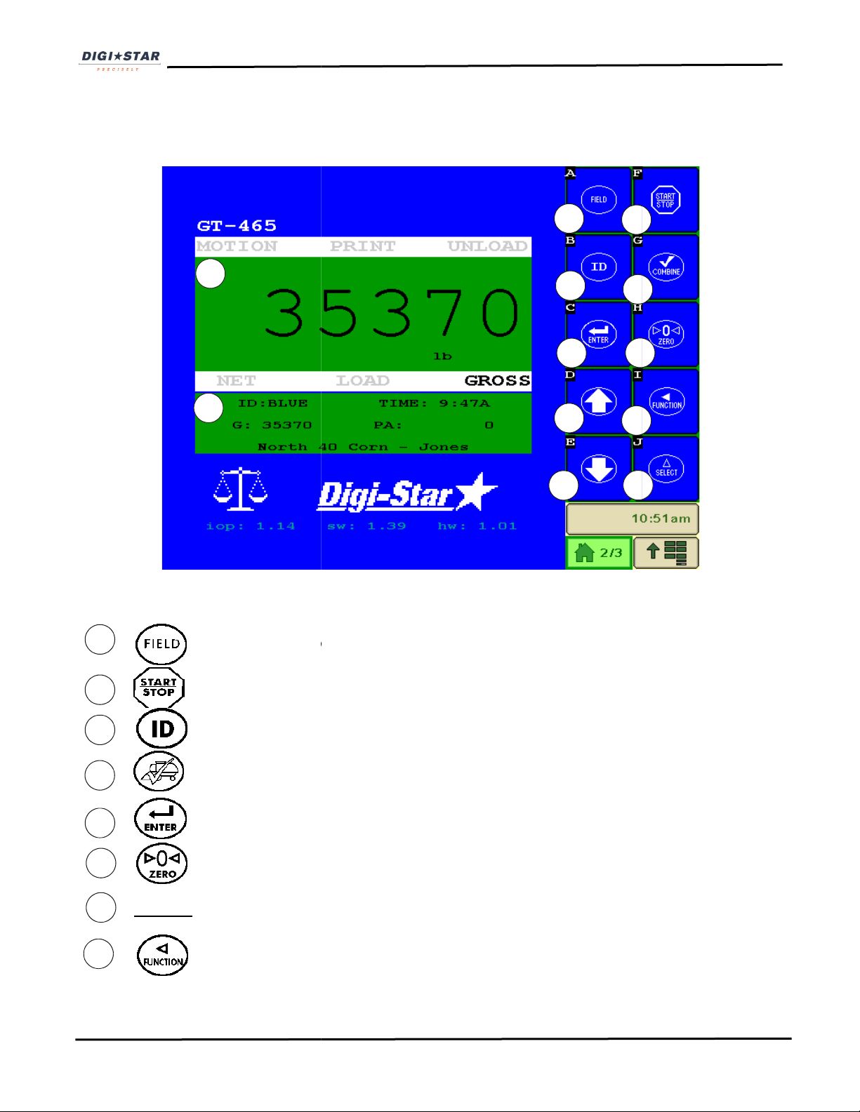
INDICATOR OVERVIEW
- Press and hold to zero balance the scale
- Start or stop unloading operation
- Enter and exit ID screen (page 9)
- Enter and exit FIELD screen (page 8)
- Check combine yield monitor (page 24)
- Accept change or proceed to next item
Directional Arrows – Left or right arrows move cursor inside data field. Up and Down arrows move to
previous or next data field. List scrolls faster the longer the Up/Down arrow is held
Number Keys
6 GT465 Operators Manual D3968 Rev A
Page 7
2
3
11
9
10
12
13
14
15
1
1
2
3
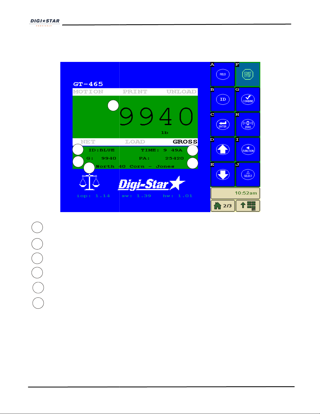
shut
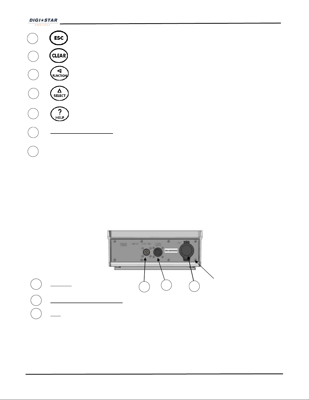
- Escape or undo last data change
- Delete one character in data entry field. Press and hold to delete entire data entry
contents.
Unloading/Loading indicator – arrow icon displayed during loading and unloading operations.
Main Display area
- Performs task displayed by select
- Scroll thru function key operation
- For additional information
INDICATOR DISPLAY SCREENS
The GT465 acts as a remote display, but can perform all scale operational functions normally done on the Virtual
Terminal. The main difference is the addition of the 3 line display shown on the VT.
BOTTOM PANEL CONNECTIONS
Load Cell
Power/ISOBUS/Rotation Sensor
USB – Port for USB Flash drive
Make sure
door snaps
D3968 Rev A GT465 Operators Manual 7
Page 8

1
2
3
1
2
3
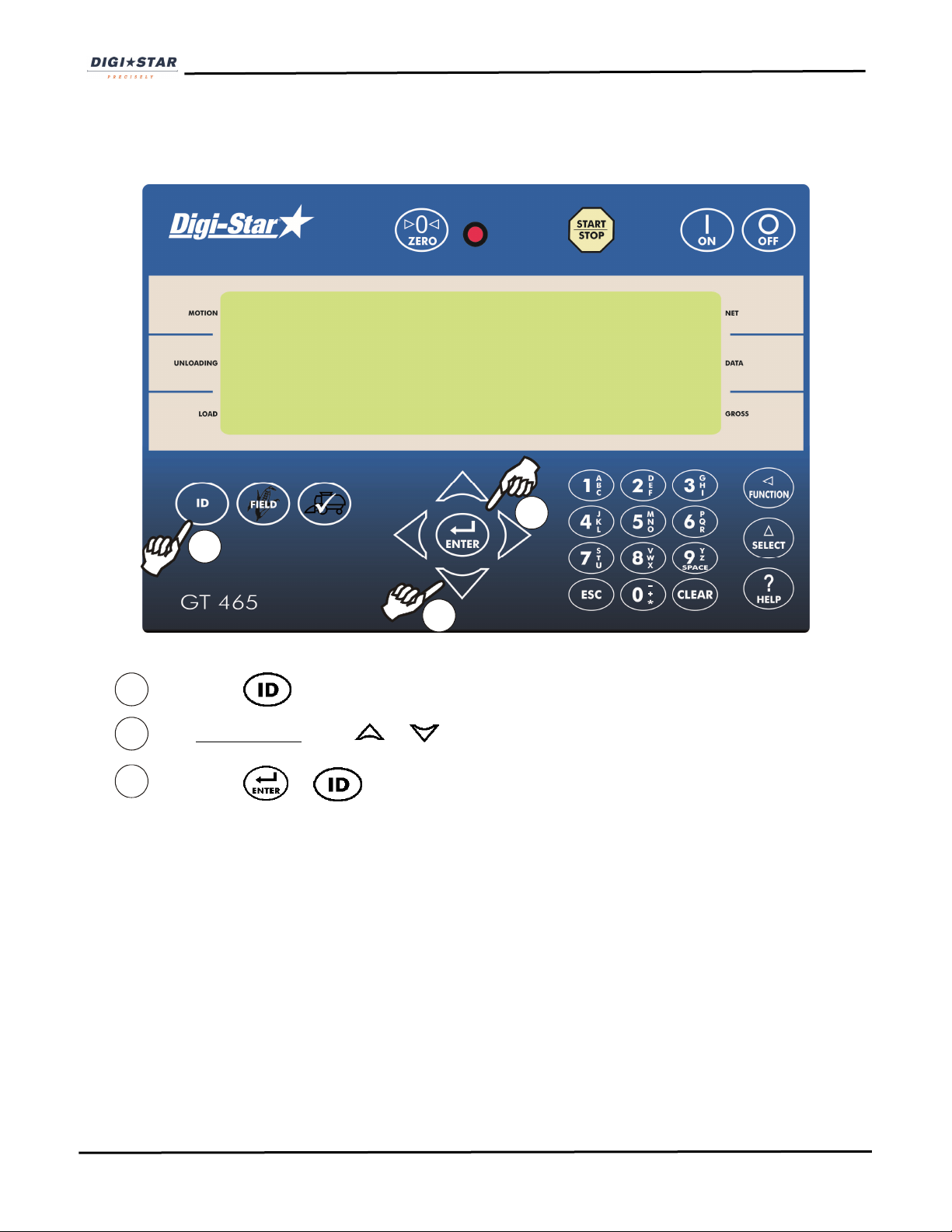
SELECTING FIELDS AT GT465 INDICATOR
NOTE: Field names can be uploaded from a PC using a USB flash drive. See page 21.
F l d
F l d 1111
F l d F l d
Press to select field, current field number will be shown.
Up/Down Arrows – Press or to scroll through fields (150 maximum).
Press or to exit.
8 GT465 Operators Manual D3968 Rev A
Page 9
1
2
3
1
2
3
SELECTING ID'S AT GT465 INDICATOR
NOTE: ID names can be uploaded from a PC using a USB flash drive. See page 21.
I D 1
I D 1
I D 1I D 1
Press to select field, current ID will be shown.
Up/Down Arrows – Press or to scroll through IDs (150 maximum).
Press or to exit.
D3968 Rev A GT465 Operators Manual 9
Page 10
VIRTUAL TERMINAL OVERVIEW
differ from this display
Enter and exit Field Screen
Start or stop unloading operation
Enter and exit ID screen
k combine yield mon
change or proceed to next item
Press and hold to zero balance the scale
Up arrow moves to previous date field
Performs ask displayed by select
11
12
2
3
4
5
6
8
1
7
1
2
3
4
5
6
7
8
9
10
NOTE: Your VT may
—i.e. key placement, layout
Up Arrow –
-
-
-
- Chec
- Accept
-
-
(page 14)
(Page 15)
itor (page 24.)
10
GT465 Operators Manual
D3968 Rev A
Page 11

10
9
11
12
Down Arrow – Down arrow move to the next data field
- Scroll thru function key operation
Upper Display Window – Display current actions or weight – 6 characters.
Lower Display – Displays recorded data – 26 characters x 3 rows
VIRTUAL TERMINAL DISPLAY SCREENS
Four display screens can be shown on the Virtual Terminal:
Active Screen
Statistics including ID, Time, Gross Weight, Print Accumulator and Field Name. (See page 12)
Data Record Screen
Data records including Field Name, Net Weight, Print Accumulator, ID, Date and Time. (See Page13)
Field Screen
150 field names are available and can be modified using the keypad. (See Page 14)
ID Screen
150 ID names are available and can be modified using the keypad. See (Page 15)
D3968 Rev A GT465 Operators Manual 11
Page 12
: The VT needs to be on this screen before loading
Print accumulator (PA) for current field
1
2
3
4
1
2
3
4
5
6
5
6
ACTIVE SCREEN
NOTE
or unloading.
Current Weight
Current ID name
Current gross weight
Current field name
Time
12
GT465 Operators Manual
D3968 Rev A
Page 13

DATA RECORD SCREEN
NOTE:
This screen is shown for only 10
” containing these data fields each time the operator completes a load.
to scroll through all previously stored records
weight that was unloaded for this load)
ID name (6 characters) (Use for CART ID or TRUCK ID)
weight ( total of all loads for selected field
1
2
3
4
1
2
3
4
5
6
7
5
6
7
seconds before reverting to the Active screen.
The indicator creates “data records
• Press or
.
Load number
Field name (26 characters)
Weight (
Date
Time
Accumulated
D3968 Rev A
GT465 Operators Manual
13
Page 14

Field names can be uploaded from
maximum of 26 characters long.
VT
modify or select field. Current field number is shown in upper display.
Three lines are displayed in Lower Display Window. The top line of the three is current,
editable and will be used for next data record.
or
Every VT has different functionality to modify
Please refer to the owner’s manual for instructions.
to exit
2
1
2
3
4
5
VT
or
ield to edit and
1
3
4
5
NOTE:
Field names can be a
Field names can be changed using the
FIELD SCREEN
a PC using a USB flash drive. (See page 21)
before unloading.
Press to to
Up/Down Arrows – Press
interface to modify)
Press or
to scroll through fields (150 maximum).
field names. (Selecting F
14
GT465 Operators Manual
D3968 Rev A
Page 15

ID names can be uploaded from a PC usi
ID names can be a maximum of 6 characters long.
can be changed by using the keypad before unloading.
to modify or select ID name. Current ID number is shown in upper display.
Three lines are displayed in Lower Display Window. The top line of the
will be used for next data record.
Every VT has different functionality to modify
Please refer to the owner’s manual for instructions
to exit.
2
1
2
3
4
5
three is current, editable and
(Selecting ID to edit and interface to
1
3
5
NOTE:
ID names
ID SCREEN
ng a USB flash drive. (See page 21)
Press
Up/Down Arrows – Press
modify)
Press or
or to scroll through ID names (150 maximum).
field names.
D3968 Rev A
GT465 Operators Manual
15
Page 16

E N T E R
= e r a s e
1
2
3
5
6
Clearing The Indicator Memory Before Starting A Season
Before starting the harvest each year you will want to clear out the last year’s data records and accumulators to
start over with a clean slate. You may have some new field names and ID names to store into the indicator as
well.
Important:
Important:
Before erasing the data records, be sure that the data records have been safely stored.
This action will erase all data records.
Erase Grain Tracker™ Data Records
1. Press and release, scale will show a flashing 0
2. Press and Hold until PRINT BUFFER displays.
3. Release .
4. Display scrolls ENTER = ERASE, ESC = EXIT
5. Press erases all records.
6. Press to return to active screen without erasing records.
16 GT465 Operators Manual D3968 Rev A
Page 17

2
3
4
4
4
Zero Accumulator Memory
A C C U M
1. Select field name of accumulator to be erased. See page 8. Return to the active screen.
2. Press repeatedly until ACCUM is displayed.
3. Press
4. Press to delete current field accumulated value, press to erase all 150 accumulated
records, or press to exit.
NOTE: This operation only erases the accumulator data, field names, ID names and data records are not
affected.
NOTE: This operation can also be performed via the VT interface.
D3968 Rev A GT465 Operators Manual 17
Page 18

DAILY DATA COLLECTION
Insuring your data is secure from theft, fire or equipment failure requires a small effort each day to store your data
on a USB flash drive.
Mid-Season Name Changes
During the season, you may wish to delete and add field names or ID names to your scale indicator memory. This
may be done in one of three ways.
Front Panel (GT465)
For a small amount of changes, edit field names and ID names using the VT interface. See pages 14 - 15 to
edit field and ID names. See page 17 to erase accumulator memory.
Virtual Terminal
For a small amount of changes, edit field and ID names using the virtual terminal. See your VT owners’ manual
for information on how to select and edit strings on the VT. To erase accumulator memory follow same
procedure found on page 17.
Upload New Field Names, ID Names and Accumulator Using USB Flash Drive
For a large number of changes, perform the changes on your PC using Grain TrackerTM software and then
transfer the new information to the indicator using a USB flash drive.
Before doing this, transfer your existing field accumulator data from the indicator to the USB flash drive and
onto your PC. This keeps the proper accumulator values on partially finished fields.
Modify Field Names And ID
Using Grain Tracker™ software:
1. Upload data records from USB flash drive to the PC.
2. Delete field names that are already finished and clear their accumulators.
3. Add new field names as needed.
4. Transfer the new field names, accumulators and ID names onto the USB flash drive.
NOTE: To upload data to indicator, you must first create data files with field names, ID names and accumulator
values using Grain Tracker™ software.
18 GT465 Operators Manual D3968 Rev A
Page 19

TRANSFER DATA
Open door and insert
USB flash drive here
to download data
records
The GT465 is equipped with a USB flash drive port. The USB flash drive used with the indicator holds thousands
of data records and allows for easy transfer to PC.
U S B I N
Insert USB flash drive. The GT465 will automatically detect the USB flash drive and display the following:
ENTER – SAVE RECORDS to USB
1 - FIELD + ID TO USB
9 - USB TO FIELD + ID
D3968 Rev A GT465 Operators Manual 19
Page 20

2
1
1
To Store Data Records on a USB Flash Drive
E n t e r - s a v e
1. Press to save records to USB. Wait for data transfer to be completed.
NOTE: This action appends values already on the USB flash drive. No data is lost.
To Store Field and IDs on A USB Flash Drive
1 - F I E L D
1. Press to transfer the field and ID names onto the USB flash drive. Wait for data transfer to be
completed.
2. Press
3. Remove the USB flash drive from the USB port.
20 GT465 Operators Manual D3968 Rev A
Page 21

1
2
1. Press 9 to transfer field names and ID names from USB flash drive to indicator. Wait for data
2. Press to exit. Remove USB flash drive from socket. Display returns to active screen.
Important:
Transfer Field And ID Data From USB To Indicator
9 - U S B t o
transfer to be completed.
This action will overwrite field names, ID names and accumulator in the indicator.
D3968 Rev A GT465 Operators Manual 21
Page 22

: For more information on AutoLog, please refer to D3908 AutoLog manual.
required field name. See page 14
select required ID. See page 15.
og is functioning, simply start the PTO. Scale will read Zero and enter the net mode.
Unload grain from grain cart. The Upper Display
amount left on cart) is displayed on second line of Lower Display.
If AutoLog is functioning, simply stop the PTO. Data record will be stored, display
ot working
: Make sure Indicator has returned to the
shows the amount unloaded. Gross value (tota
for troubleshooting and setup instructions.
1
2
Record Data (W/ AutoLog)
NOTE
1. Press to select
2. Press to
active screen.
3. If AutoL
4.
5.
NOTE: If AutoLog is n
correctly, see page 38
NOTE
l
ed and printed.
22
GT465 Operators Manual
D3968 Rev A
Page 23

Record Data (Without AutoL
: To operate without AutoLog, set
required field name. See page 14
o select required ID. See page15
before unloading grain from cart. Scale will read zero and enter the net mode
ain from grain cart. The Upper Display shows the amount to unloaded. Gross value (total
amount left on cart) is displayed on second line of Lower Display.
once the unloading process is complete.
When the unloading process is complete:
The data record is stored in memory.
The data record screen will display the last data record
The indicator will return to active screen.
: Make sure Indicator has returned to the active
1
2
3
3
5
og)
NOTE
1. Press to select
2. Press t
screen.
3. Press
RSSCTL
(DAN 531) to
. NOTE
OFF.
See pages 30-34.
.
4. Unload gr
5. Press
•
• The data record is printed.
•
•
for 20 seconds.
D3968 Rev A
GT465 Operators Manual
23
Page 24

to see last data record.
through
After 10 seconds of no keypad activity, the Indicator will return to the active screen.
Check Combine Yield Monitor
For best accuracy, park on a level surface when checking.
to select desired name.
1
2
1
Recorded Data Preview
1. Press or
2. Press or to scroll
3.
recorded data.
1. Press
24
GT465 Operators Manual
D3968 Rev A
Page 25

2. Lower display will show
between display the net weight and
3. Unload grain from grain cart. The Upper Display shows the amount unloaded. Gross value (total amount
left on cart) is displayed on second line of Lower Display.
4. When finished unloading press . Data record will be stored, displayed and printed.
WEIGH COMBINE GRAIN
COMBIN
and Upper Display will show
UNLOAD
, then alternate
RE-CALIBRATING YOUR SCALE
To re-calibrate your scale, document at least 3 to 6 loads of varying sizes and measure the actual weight of all
loads on a certified scale.
• It must be assured that each truck is not losing grain in transit to a certified scale.
• Weigh the truck immediately before unloading and immediately after unloading to minimize errors due to
changes in fuel etc.
In this example, we are unloading six carts of grain onto four semi-trucks.
Example:
Cart Load A 51560
Cart Load B 33240
Cart Load C 17620
Cart Load D 50420
Cart Load E 38200
Cart Load F 12360
Total Indicator Weight 203400
Truckload #1 51920
Truckload #2 51320
Truckload #3 50720
Truckload #4 51070
Total Certified Weight 205030
Reading Too High
If the Indicator is reading higher than the certified scale, then the calibration number is high and should be
decreased proportionally. See page 26.
Reading Too Low
If the Indicator is reading lower than the certified scale, then the calibration number is low and should be
increased proportionally. See page 26.
D3968 Rev A GT465 Operators Manual 25
Page 26

1
1
1
2
1
Get Your Calibration Number
2 4 2 8 0
1. Enter 872 and press . The calibration (CAL) number will display. Example CAL = 24280
TOTAL CERTIFIED WEIGHT
TOTAL INDICATOR WEIGHT
X CURRENT CAL NUMBER=NEW CAL NUMBER
Using the previous example your results would be:
Enter New Calibration Number
205030
203400
X 24280 = 24475
2 4 4 7 5
1. Enter 872 and press . Existing calibration number will display.
2. Use number pad to type new number and press
For best results, unload on level ground. Make sure no grain is lost in trucking the grain to a certified scale.
26 GT465 Operators Manual D3968 Rev A
Page 27

OPTIONAL SETTINGS
is displayed.
reduces backlight intensity by 60%. Press
medium
until desired setting is shown.
to save setting and return to active screen.
again for full intensity.
1
2
1
3
2
Backlight Dimmer
1. Press until dimmer
2. Press
The unload alarm beeper can be set to:
Off – no beep, 1 – short beep, 2 –
To change unload alarm:
In the active screen:
Unload Alarm
beep, 3 – medium long beep, 4 – longest beep
1. Enter 407 and press
2. Press
3. Press
D3968 Rev A
GT465 Operators Manual
27
Page 28

arrow to move cursor.
Press arrow to move cursor. Format dd
1
2
2
3
3
4
4
1
1
1
1. Enter 202 and press .
Change Time
2. Press
3. Press to set time.
4. Press .
Change Date
1. Enter 204 and press .
2.
3. Press arrow to set date.
4. Press .
28
/mm/yy.
GT465 Operators Manual
D3968 Rev A
Page 29

Preset Active Signal
The Preset Active Signal function was designed to allow greater flexibility and application specific use of the
GT465 scale indicator Alarm Out relay. This feature uses a combination of settings to program the 12 volt relay
on the GT465, with the ability to enter a preset weight. With this programming control, the GT465 can be
connected to a variety of accessories such as external alarms, hydraulic solenoids, and other electronics. The
preset is activated by the START/STOP button or AutoLog for use of more hands free applications.
(For more detailed operations, please refer to document D3980 Preset Active Signal Functionality)
To enable this function set on the GT465 indicator:
1) Press 477 then Select. Press Select again to change ALP setting to “ON”. Press ON button to store.
The GT465 is now in Auto Load Preset mode. This setting allows preset weight values to be entered with
the keypad, so that the GT465 can control other functions based on a target weight. Turn this setting
OFF for normal grain cart mode.
2) Press 406 then Select. Press Select to change the RELAY function. Press ON button to store. The
RELAY function defines what function the GT465 performs when the preset weight is activated during the
unloading process. This can be held at 12 V while the preset is active (PREACT), or activate 12 V once
the preset weight is reached during unloading (PRNOPA).
3) Press 475 then Select. Type in time for PAST setting, if needed. Press ON button to store. The PAST
setting is the time (0.0 to 99.9 seconds) for the RELAY function to timeout. If RELAY is set as PREACT
and is held at 12 V during the entire unload process, this setting extends the time at which the relay
remains at 12 V. If RELAY is set as PRNOPA and activates 12 V at the end of the unload cycle, this
setting determines how long the relay stays on after the target weight is reached.
4) Press 442 then Select. Press Select to choose WEIGHT or PERCNT; WEIGHT is preferred choice for
this application. Press ON button to store. Type in TOLER value. Press ON button to store. This is
normally the weight value of grain still unloading; set to help prevent overfilling the truck. If the implement
unloads by 1000 pounds too high each time, the TOLER value should be set to 1000.
5) Use keypad to type in preset weight to be unloaded, and then press ENTER. If 5000 pounds is entered,
this is the range at which the relay functions above will activate.
Example Application 1: Grain cart with GT465 AutoLog system is to activate an external alarm light to notify truck
driver that cart is unloading. Truck is allowed to hold 40,000 pounds. Grain cart operator opens and closes
doors, and wants to make sure an additional 30 seconds are allowed for cleanout before truck drives away.
Set 477 ALP to ON. Set 406 RELAY to PREACT. Set 475 PAST to 30.0. Press 40000 then ENTER to store
preset weight value. Connect green DC Output wire to external alarm light +12V, black to – /Ground.
Operation: Start PTO, GT465 automatically loads 40,000 pound preset, external alarm light flashes for truck
driver. Open door to unload grain, then close door when near 40,000 pounds. Target weight is reached; 30
second delay time begins to give cart operator time to clean out auger and turn off PTO. After 30 seconds,
external alarm light turns off, data is logged, and truck drives away.
Example Application 2: Grain cart with GT465 AutoLog system is to activate an alarm in tractor cab for 10
seconds to notify operator once 35,000 pounds is unloaded, so that the door can be closed. The operator has a
history of overloading the truck by 5000 pounds each time.
Set 477 ALP to ON. Set 406 RELAY to PRNOPA. Set 475 PAST to 10.0. Set 442 to WEIGHT; TOLER to 5000.
Press 35000 then ENTER to store preset weight. Connect green DC Output wire to alarm +12V, black to ground.
Operation: Start PTO, GT465 automatically loads 35,000 pound preset. Open door to unload grain. Target
weight is reached 5000 pounds early, sounding alarm for operator to close the door. The preset is deactivated at
30,000 pounds to correct for overfill, and the data is logged when the PTO is stopped.
D3968 Rev A GT465 Operators Manual 29
Page 30

SETTING OPTIONS
To modify options use the following chart, while on the active screen on the GT465:
1. Enter D.A.N. (Direct Access Number) and press to enter selected option.
2. Press repeatedly until desired selection is shown.
3. Press to set.
Setting/
Display
Language
(LANGAG
LANGAG)
LANGAGLANGAG
D.A.N Options
(
Bold
= Default)
MENU 1. BASIC FEATURES IN MOST INDICATORS
101
ENGL
ENGLSH
SH
ENGLENGL
SHSH
NEDERL
FRANCS
DEUTSH
ITAL
PORT
ESPAN
DANSK
MAGYAR
VESTA
Description
Select from list
English
Dutch
French
German
Italian
Portuguese
Spanish
Danish
Hungarian
Spanish
Display Update
Rate
(
DDDD----Rate
Rate
)
RateRate
Motion Arrow
(
Mot
MotIIIIon
on
onon
)
)
MotMot
Zero Tracking
(
ZTRACK
ZTRACK
ZTRACKZTRACK
30 GT465 Operators Manual D3968 Rev A
102
103
104
1,2,3,4
ON/
OFF
ON/
OFF
Update display times per seconds.
Arrow flashes for unstable weight.
Set to OFF.
Page 31

Setting/
D.A.N Options
Description
Display
Weigh Method
(
W MTHD
W MTHD
W MTHDW MTHD
Scroll
(
SCROLL
SCROLL
SCROLLSCROLL
Time Format
(
TIME F
TIME F
TIME FTIME F
Set Time
(
TIME
TIME
TIMETIME
)
)
MENU 2. CLOCK, PRINTER, COMMUNICATION & ESTIMATED WEIGHT FEATURES
)
)
105
118
201 24 HR
202
(
Bold
= Default)
1=General,
2=Fast,
3=Slow,
4=Lock-On
0,1,2,3,4,5,6,7,8,9
AM/PM
XX:XX:XX
Use general.
Sets scroll rate of Display.
24-hour time format.
increments each digit
and “ARROW” keys advance
cursor to set date “mmddyy” field.
Date Format
(
DATE F
DATE F
DATE FDATE F
Set Date
(
DATE
DATE
DATEDATE
Computer in Mode
(
COM
COM IN
COMCOM
)
IN
ININ
)
)
203
204
215 DOWNLD, EZ
1,2,3,4,5,6,7,8
Enter XXXXXX
CMD,
EZ2CMD
Select date format.
1 = mm – dd
2 = mm/dd/yy
3 = mm/dd/yyyy
4 = dd/mm
5 = dd/mm/yy
6 = dd/mm/yyyy
7 = dd/mm/yy
8 = dd/mm/yyyy
changes date, “ARROWS”
advance cursor to set date.
DOWNLD = Data Down Loader, EZ
CMD = Original EZ Commands,
EZ2CMD = EZII Escape
Commands.
D3968 Rev A GT465 Operators Manual 31
Page 32

Setting/
D.A.N Options
Description
Display
Print Accum.
(
ACCUM
ACCUM
)
ACCUMACCUM
BUFFER
(
BUFFER
BUFFER
BUFFERBUFFER
PBLine
(PBLINE
PBLINE)
PBLINEPBLINE
Remote Terminal
(RMTERM
RMTERM)
RMTERMRMTERM
IsoBus Weight
(ISO WT
ISO WT)
ISO WTISO WT
)
(
Bold
= Default)
223
238
239
251
252 OFF, .1, .2, .3, .4,
0
ON
1,2,3
ON
/OFF
.5, .6, .7, .8, .9,
1.0
, 1.1, 1.2, 1.3,
1.4, 1.5, 1.6, 1.7,
1.8, 1.9, 2.0
Shows a running total of weights
printed.
Set to ON
Use 3
When ON, sends information to a
Remote Terminal
Selects rate to broadcast ISOBUS
weight data.
Disable RMport
Response
(RMNOP
RMNOPRRRR)
RMNOPRMNOP
Disable ISOBUS
VT Message
(ISO VT
ISO VT)
ISO VTISO VT
Use ISOBUS DDI
values
(ISODDI
ISODDI)
ISODDIISODDI
255
257
258
ON
ON,
ON,
/OFF
OFF
OFF
ON, disables sending ‘print’ type
response to cmds received.
ON, enables ISOBUS gateway to
send VT messages.
ON, Sends ISO WT using ISOBUS
DDIs 229 & 232
OFF, use D/S legacy DDIs
32 GT465 Operators Manual D3968 Rev A
Page 33

Setting/
D.A.N Options
Description
Display
Display Count
(
COUNT
COUNT
)
COUNTCOUNT
Display Unit
(
LB
LB----KG
KG
)
LBLB
KGKG
Capacity
(
CAP
CAP
)
CAPCAP
MENU 4. PRESET, BATCHING & ROTATION COUNTER FEATURES
Relay
(
RELAY
RELAY
)
RELAYRELAY
(
Bold
= Default)
MENU 3. SCALE CALIBRATION SETTINGS
301 .01,.02,.05,.1,.2,.5,
1,2,5,10,20,
50,100
303
304
406
LB
/KG
85,000
OFF
, SETPNT,
PRESET,SEEDTD,
PRNOPA, PREACT
Minimum weight change that is
displayed.
Note: If this is too small, scale will
be unstable.
Unit of measure.
Note: If this changes, calibration
and set-up must change.
Maximum capacity of scale.
Selects behavior for the +12VDC
output.
U-Alarm
(UALARM
UALARM)
UALARMUALARM
Tolerance Method
(T MTHD)
Tolerance
(TOLER)
Preset Active
Signal Timeout
(
PAST
PAST
PASTPAST
Unload Weight
Display
(
unwedi
unwedi
unwediunwedi
Auto Load Preset
(
ALP
ALP
ALPALP
)
)
)
407
442 WEIGHT
442 Manual Entry Set tolerance weight to compensate
475 Enter XX:XX Time to continue preset active
476
477
1
,2,3,4
PERCENT
NET,
LOAD
ON
GROSS,
, OFF
Adjust unload alarm setting
Tolerance offset method
for truck overfill
signal after preset is reached.
NET = From Zero, GROSS =
Display total weight, LOAD =
Unload from preset
If ON – Load stored preset when
unloading begins.
D3968 Rev A GT465 Operators Manual 33
Page 34

Setting/
D.A.N Options
Description
Display
Diagnostic Enable
(
DIAG
DIAG)
DIAGDIAG
RPM Start/Stop
Control
(rssctl
rssctl)
rssctlrssctl
RPM/Stop Speed
(rssmin
rssmin)
rssminrssmin
Rpm Start Tol
Speed
(rsstol
rsstol)
rsstolrsstol
RPM Start Delay
(rsstoy
rsstoy)
rsstoyrsstoy
508
531
532
533
534
(
Bold
= Default)
MENU 5. CONTROL SETTINGS
ON
, OFF
ON,OFF
300
100
3.0
Enables diagnostic information. –
Press SELECT do display DIAG,
then press FUNCTION to display
RPM
ON, enables AUTOLOG feature
Set to 20 – 50% of PTO operating
RPMs. Stop is activated with this
value.
Set to 10% of PTO operating
RPM’s. Start is activated using the
value + DAN 532.
Start activated when RPMs above
DAN 532 + DAN 533 for this time in
seconds.
RPM Stop Delay
(rsspoy
rsspoy)
rsspoyrsspoy
Setup Number
(
SETUP
SETUP
)
SETUPSETUP
Calibration Number
(
CAL
CAL
)
CALCAL
535
871 Quick entry method selects weigh
872 Weight displayed at .4mV/V for
2.0
CALIBRATION
Stop activated when RPMs below
DAN 532 for this time in seconds.
method 1-4lbs, 5-8kg, gain 1-9,
display counts 1-9 and capacity
*1000.
these load cells.
34 GT465 Operators Manual D3968 Rev A
Page 35

WEIGHING ERRORS
OVRCAP
Capacity Limit:
Weight on scale system exceeds capacity limit.
+RANGE
Over Range:
Weight on scale system exceeds maximum weight.
-RANGE
Under Range:
Weight on scale system less than minimum weight.
HARNESSES and CONNECTIONS
D3968 Rev A GT465 Operators Manual 35
Page 36

RAIL MOUNT
WING MOUNT
WEDGE MOUNT
RAM MOUNT
INSTALLATION
INDICATOR MOUNTING
KEY PART NUMBER DESCRIPTION
A 404353 BRACKET-EZ3 PLASTIC RAIL
B 403780 SCR-#10 X 5/8 FHSTS BLACK ZP
C 840459 SUPPORT-HAT BRACKET
D 405069 U-BOLT 1/4-20 X 3.25 ZP
E 405084 NUT-1/4-20 TOP LOCKING FLANGE
F 403770 BRACKET- WING MOUNT
G 405124 PACK-WEDGE MOUNT BRACKET WITH U-BOLTS
& FLANGE NUTS
H 405244 EZ3 WEDGE MOUNT
KEY PART NUMBER DESCRIPTION
I 404799 RAM MOUNT FOR EZ 3 INDICATOR WITH
HARDWARE
J 404230 RAM SUCTION CUP W/TWIST LOCK
36 GT465 Operators Manual D3968 Rev A
Page 37

MAGNETIC
SWIVEL
MOUNT
wires to terminal
Color Key
KEY PART NUMBER DESCRIPTION
K 408880 MOUNT FOR EZ 3 INDICATOR WITH HARDWARE
AND MAGNET
L 408828 MOUNT FOR EZ 3 INDICATOR WITH HARDWARE
WITHOUT MAGNET
CONNECT LOAD CELLS TO J-BOX
Connect load cell
blocks. See Wire
J-Box Illustrated for 4
Load Cell Installation
Wire Color Key
Color Description
1 White Signal +
2 Green Signal 3 Red Excitation +
4 Black Excitation 5 Shield Shield
Tighten Nuts
J-Box Cable
D3968 Rev A GT465 Operators Manual 37
Load Cell Cable
Connect to Indicator
bottom Panel.
J-Box Connections
Page 38

TROUBLESHOOTING
is displayed.
diagnostics.
The 3 line display will now show value from RPM sensor.
to disable diagnostics and return to normal operation.
The RPM value should be close t
For best results adjust the distance between the sensor and the targ
This is equal to the thickness of one to two quarters.
Sensor has yellow LED indicator on rear to indicate target in range of the sensor.
o the actual RPM’s of the shaft when detecting a single target per
et to between 0.1” and 0.2” (2mm
3
1
2
4
RPM Sensor Diagnostics
1. Press until
2. Press to enable
3.
4. Press
NOTE:
revolution.
DIAG
-5mm).
38
GT465 Operators Manual
D3968 Rev A
Page 39

1
1
2
3
1
1
2
3
Verify AutoLog Settings
Verify that your AutoLog setting located in Menu 5 are correct. These settings include D.A.N. numbers 531 and
532. See page 30-34 for default settings. Your settings may vary.
EXAMPLE: Turn RSCCTL to “ON”
1. Enter 531, then press .
2. Press to set
3. Press to save setting and return to active screen.
RSCCTL
to “ON”.
EXAMPLE: Turn RSSMIN to “300”
1. Enter 532, then press .
2. Enter 3, 0, 0 on keypad
3. Press to save setting and return to the active screen.
D3968 Rev A GT465 Operators Manual 39
 Loading...