

Page 1
US
Part Number: D3570A
10/24/2001
Page 2

Digi-Star EZ3200/EZ3200V/EZ3200V RC
Table of contents
Table of contents
1. About the product.............................................................................................................................. 1
FEATURES OF MODELS EZ3200, EZ3200V AND EZ3200V RC................................................1
OPERATING SPECIFICATIONS.................................................................................................... 1
HOUSING.......................................................................................................................................... 1
2. Mounting and connection ................................................................................................................. 2
INDICATOR MOUNTING ............................................................................................................... 2
POWER CONNECTION................................................................................................................... 2
POWER CABLE CONNECTIONS .................................................................................................. 2
INDICATOR BOTTOM PANEL CABLE CONNECTIONS ........................................................... 2
REMOTE ALARM CONNECTION ................................................................................................. 2
REMOTE INPUT CONNECTION ................................................................................................... 2
LOAD CELL CONNECTION ........................................................................................................... 3
LIGHTNING PROTECTION ........................................................................................................... 3
TECHNICAL MANUAL ................................................................................................................... 3
3. Setup and Calibration Requirements .............................................................................................. 4
TO RUN THE SELF TEST............................................................................................................... 4
4. Matching EZ scale to another scale ................................................................................................. 5
SCALE MATCHING EXAMPLE ..................................................................................................... 5
SCALE INFORMATION SHEET .................................................................................................... 5
SCALE MATCHING WORK SHEET .............................................................................................. 5
CONNECTING EZ INDICATOR TO OTHER LOAD CELLS ....................................................... 6
TO CHANGE THE SETUP & CALIBRATION NUMBERS .......................................................... 6
TO RETURN TO WEIGH MODE .................................................................................................... 7
5. Getting started .................................................................................................................................. 8
6. System operation............................................................................................................................... 9
TURNING ON THE SCALE ............................................................................................................9
TURNING OFF THE SCALE .......................................................................................................... 9
TO ZERO BALANCE THE SCALE ................................................................................................. 9
USING THE HELP KEY ................................................................................................................ 10
TO SELECT GROSS MODE .......................................................................................................... 10
TO SELECT NET MODE ............................................................................................................... 10
TO SELECT HOLD MODE............................................................................................................ 11
TO EXIT HOLD MODE.................................................................................................................. 11
TO CANCEL HOLD MODE ........................................................................................................... 11
TO ENTER A PRESET ................................................................................................................... 12
TO CLEAR THE PRESET ALARM ............................................................................................... 13
TO CLEAR THE PRESET ALARM USING THE TR OPTION................................................... 13
TO PRELOAD A TARE VALUE .................................................................................................... 14
TO USE THE PRE-ALARM ........................................................................................................... 15
TO CHANGE THE PRE-ALARM VALUE .................................................................................... 15
TO START THE MIX TIMER ........................................................................................................ 16
TO CLEAR THE MIX TIMER........................................................................................................ 16
TO RESTART THE MIX TIMER ................................................................................................... 16
TO START THE ROTATION COUNTER ..................................................................................... 17
TO CLEAR THE ROTATION COUNTER..................................................................................... 17
TO RESTART THE ROTATION COUNTER ................................................................................ 17
PROGRAMMING RECIPES .......................................................................................................... 18
TO PROGRAM A NEW RECIPE ................................................................................................... 19
TO CHANGE THE ENTRY METHOD.......................................................................................... 20
Page 3

Digi-Star EZ3200/EZ3200V/EZ3200V RC
Table of contents
6. System operation (continued)......................................................................................................... 21
TO EDIT A RECIPE ....................................................................................................................... 21
TO ERASE A RECIPE .................................................................................................................... 22
TO PRINT A SINGLE RECIPE ..................................................................................................... 23
TO PRINT ALL RECIPES.............................................................................................................. 23
USING THE AUTO ADVANCE FEATURE ................................................................................. 24
TO CHANGE THE TOLERANCE ................................................................................................. 24
USING DELAY TIME .................................................................................................................... 25
TO CHANGE THE DELAY TIME ................................................................................................. 25
TO LOAD A BATCH USING A RECIPE....................................................................................... 25
TO MANUALLY ADVANCE TO NEXT INGREDIENT .............................................................. 27
TO REVIEW A RECIPE ................................................................................................................. 27
TO REVIEW INGREDIENT ACCUMULATION.......................................................................... 28
TO PRINT ACCUMULATION FOR ONE INGREDIENT ........................................................... 28
TO PRINT ACCUMULATION FOR ALL INGREDIENTS.......................................................... 28
TO PRINT THE INGREDIENT TABLE ....................................................................................... 29
TO RENAME INGREDIENTS....................................................................................................... 29
TO ERASE ACCUMULATION FOR ONE INGREDIENT .......................................................... 30
TO ERASE ACCUMULATION FOR ALL INGREDIENTS......................................................... 31
7. Optional features............................................................................................................................. 32
REMOTE DISPLAY ........................................................................................................................ 32
TR: RADIO CONTROL OPERATION ........................................................................................... 32
PRINT WEIGHT DATA.................................................................................................................. 32
CLOCKOPTION.............................................................................................................................. 32
ID# OPTION.................................................................................................................................... 32
TO ENTER ID NUMBER ............................................................................................................... 32
TO DISPLAY ID NUMBER............................................................................................................32
TO USE FUNCTION & SELECT KEYS ....................................................................................... 33
TO ADD WEIGHT TO WEIGH MEMORY ................................................................................... 34
RECALL WEIGH MEMORY.......................................................................................................... 34
PRINT WEIGHT MEMORY........................................................................................................... 34
CLEAR WEIGH MEMORY ............................................................................................................ 34
WEIGH AVERAGING .................................................................................................................... 35
BLACK OUT.................................................................................................................................... 35
PULSED OUTPUT ......................................................................................................................... 36
APPENDIX 1: Ingredient names ....................................................................................................... 37
APPENDIX 2: Examples..................................................................................................................... 38
Always keep this manual by your scale indicator
All rights reserved. Reproduction of any part of this manual in any form whatsoever without Digi-Star’s express written permission is
forbidden. The contents of this manual are subject to change without notice. All efforts have been made to assure the accuracy of the
contents of this manual. However, should any errors be detected, Digi-Star would greatly appreciate being informed of them. The above
notwithstanding, Digi-Star can assume no responsibility for any errors in this manual or their consequence.
Copyright ! 2001 Digi-Star.
Fort Atkinson, Wisconsin (USA)
Page 4

Digi-Star Model EZ3200/EZ3200V/EZ3200V RC
1. About the product
1. About the product
FEATURES OF MODELS EZ3200, EZ3200V AND EZ3200V RC
"
Three recipe programming modes
- Ingredient percentage of total
- Amount per animal
- Amount per ingredient
"
Accumulation for tracking ingredient usage
"
200 Recipe memory locations
"
99 Programmable ingredient names to simplify loading & unloading
"
Ingredients can be entered in any order
"
Scrolling Help messages for easy recipe programming & operation
"
Front panel calibration without simulator or weights
"
[Select] and [Function] keys to simplify appearance and allow for future expansion
"
A Hold feature to hold the weight stable while moving the scale system
"
Large 1.7" display for greater readability (1" for Model 3200)
"
Fiber-optic back lighting for extremely long life
"
Expanded self diagnostic test capability
"
New powerful microprocessor and expanded memory
OPERATING SPECIFICATIONS
"
Temperature range: -28#C to 60#C (-20#F to 140#F)
"
Power requirements: 10.2Vdc - 16Vdc
"
Power on: 160mA, 4L.C. 350$
"
Power off: 1mA
HOUSING
"
Size (l×h×w): 10.3" × 7.2" × 5.0" (262 × 183 × 127 mm)
"
Weight (unpacked): 4.5 lbs (2.04kg)
"
Display EZ3200: 6-digit alpha numeric LCD, fiberoptic back lighting
Display height EZ3200 = 1" (25.4 mm)
Display height EZ3200V and 3200V RC = 1.7" (43.2 mm)
"
Environmental enclosure: IP65, IEC529
"
Connectors: AMP, gold plated contacts
copyright - 10/24/2001
!
1
Page 5
Digi-Star Model EZ3200/EZ3200V/EZ3200V RC
2. Mounting and connection
2. Mounting and connection
INDICATOR MOUNTING
The indicator is easily attached to the Indicator Mounting Bracket by hooking the top over the
plate and securing the bottom with two screws and nuts (size# 10 - 24 × 5/8" or M5 × 16mm).
POWER CONNECTION
Warning!
Always disconnect the indicator power cord before “jump starting” or fast charging a battery.
Disconnect all indicator leads before welding on equipment. Failure to do so can cause surges
which will damage the scale.
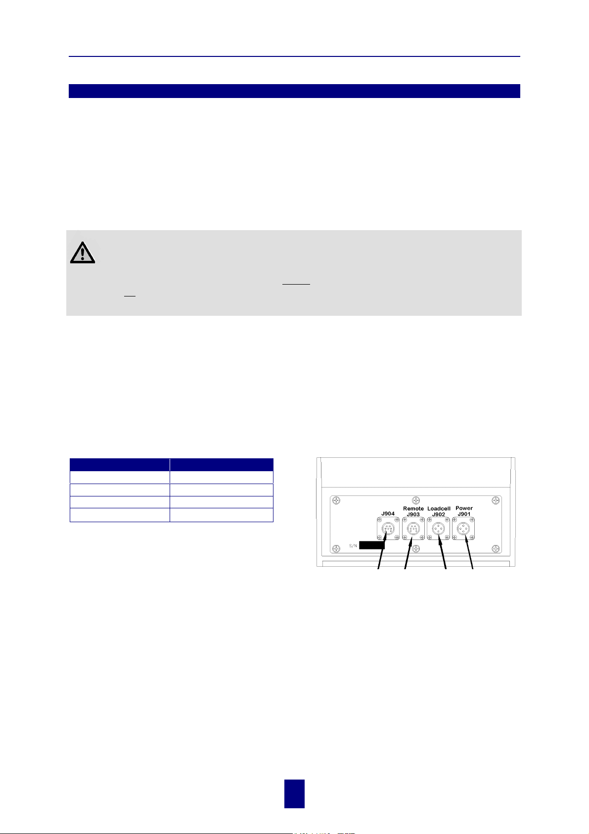
The power cable should be connected directly to a vehicle battery or regulated power supply. The
scale end of the power cable is attached to the J901 connector located on the bottom panel of the
scale.
Connect the RED wire from the power cable to +12VDC and the BLACK wire to GROUND. The
indicator is fused internally at 4 amps.
POWER CABLE CONNECTIONS INDICATOR BOTTOM PANEL
CABLE CONNECTIONS
Wire Color Wire Function
RED Battery (+12Vdc)
BLACK GROUND
ORANGE Remote Alarm Out+
BLUE Remote Input
REMOTE ALARM CONNECTION
If a remote 12 Vdc alarm is to be used, connect
the +12Vdc side of the alarm to the power cable
ORANGE wire and the GROUND side of the
alarm to the frame (= ground).
The alarm output is fused for a maximum drain of 10 amps. The remote alarm connection
!
(Optional)
Serial
Port
Cable
Remote
Display
Cable
(Optional)
Junction
Box
Cable
Power
Cable
may also be used for motor control purposes when used with a relay.
REMOTE INPUT CONNECTION
If the remote input is to be used, connect one side of the normally open momentary switch or
relay contact to the power cable BLUE wire, and the other side to the frame or other GROUND
connection. If your power cable does not contain a blue wire and you desire to use this feature,
contact your dealer for a special cable. A process control box is available for motor control and
remote enter preset capability.
2
copyright - 10/24/2001
!
Page 6
Digi-Star Model EZ3200/EZ3200V/EZ3200V RC
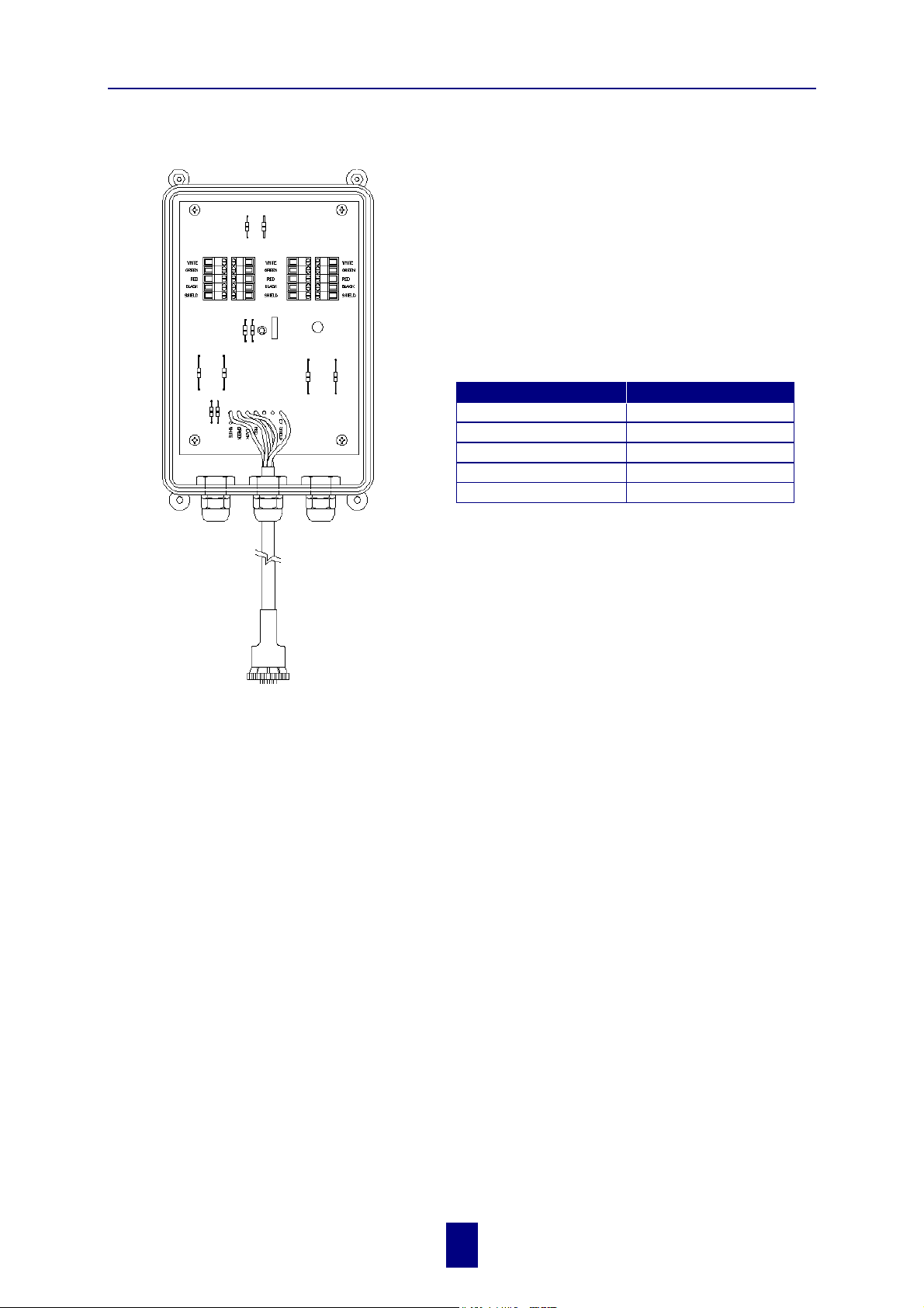
LOAD CELL CONNECTION
The indicator operates with strain gage load cells.
The system is normally supplied with a J-BOX cable
going between the scale indicator and the load cell
junction box. Extension Kits are available from your
dealer in various lengths.
To connect the load cells, attach the junction box
cable to the J902 connector on the bottom panel of
the scale. Connect the load cell cables to the junction box as shown left.
2. Mounting and connection
Terminal Color Description
WHITE SIGNAL +
GREEN SIGNAL RED EXCITATION +
BLACK EXCITATION SHIELD SHIELD
!
Follow color key on circuit board to insure proper
connection of load cell wires.
to J902 connector of indicator
LIGHTNING PROTECTION
Additional protection can be achieved with the proper installation of grounding rods. Please call
(920) 563-1400 to request Digi-Star Form F3050.
TECHNICAL MANUAL
Technical Manual available upon request. Please call (920) 563-1400 to request Digi-Star Manual
for New EZ3200.
copyright - 10/24/2001
!
3
Page 7
Digi-Star Model EZ3200/EZ3200V/EZ3200V RC
3. Setup and Calibration Requirements
3. Setup and Calibration Requirements
Warning!
This indicator was calibrated at the factory to weigh accurately with your system.
Additional calibration is not necessary under normal conditions.
The Short Form Setup & Calibration procedure allows you to change the SETUP and CAL
numbers of the indicator. You may want to perform this procedure if:
1. the indicator is being connected to different load cells, or
2. you want to adjust the calibration to match another scale system (chapter 4).
Before continuing, first write down the current SETUP and CAL numbers of your EZ indicator.
These numbers are displayed during the Self Test.
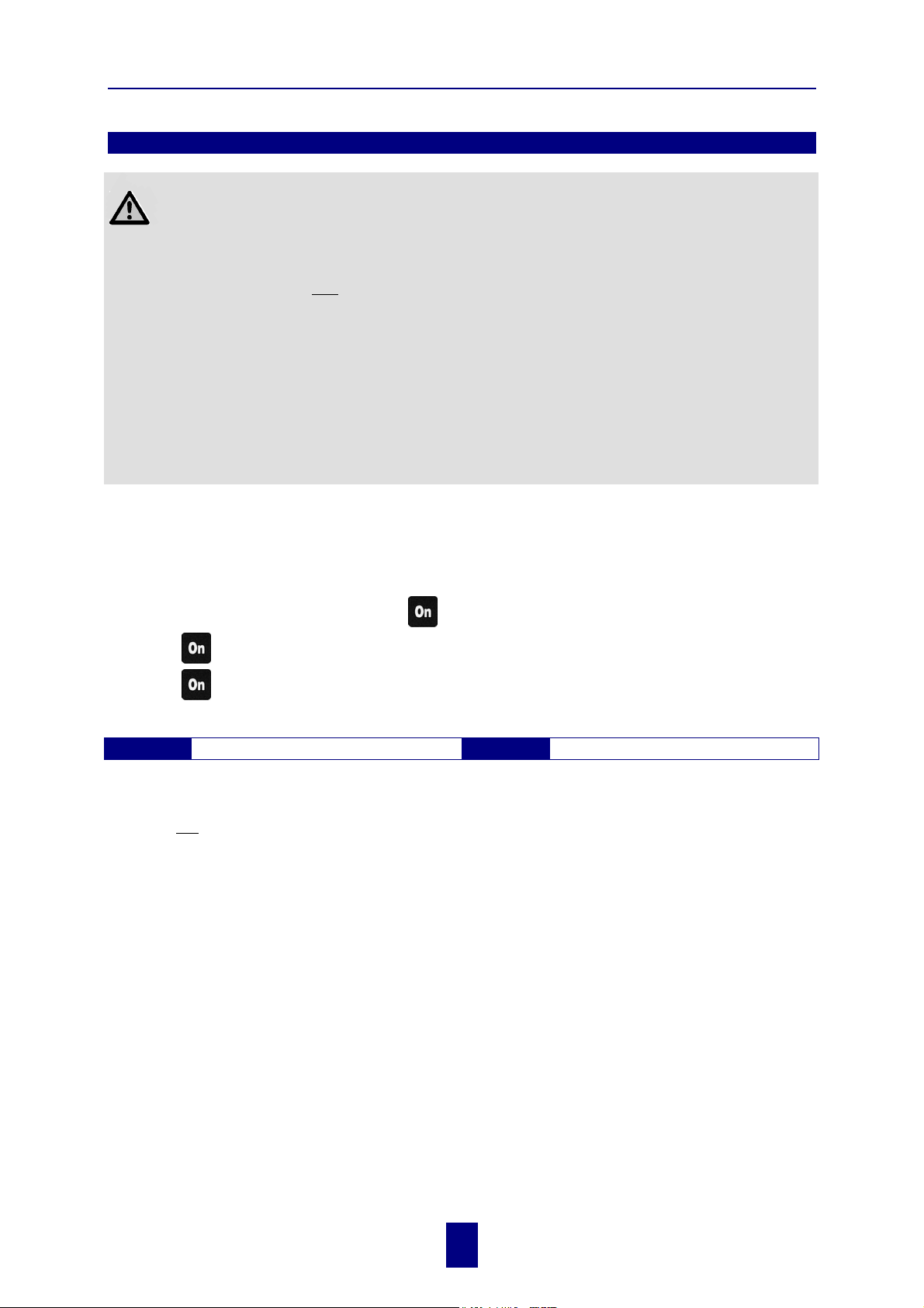
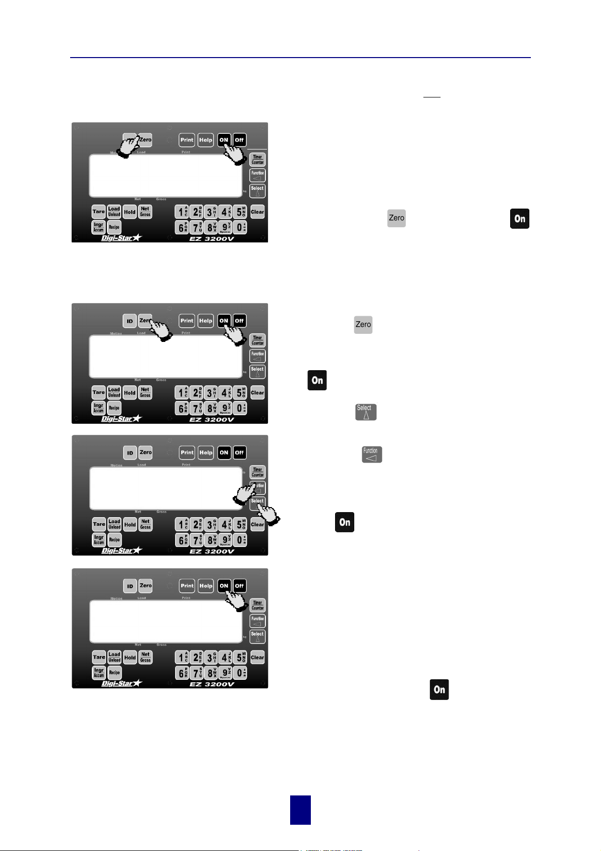
TO RUN THE SELF TEST
1. With the indicator already ON, press
2. Press
3. Press
to "pause" the Self Test while numbers are displayed.
again to "resume".
to start the Self Test.
SETUP # CAL #
Do not attempt to calibrate the scale if the indicator is not reading stable weights. The
!
calibration procedure will not fix instability, inconsistencies, or flashing "RANGE"
messages.
copyright - 10/24/2001
!
4
Page 8
Digi-Star Model EZ3200/EZ3200V/EZ3200V RC
4. Matching EZ scale to another scale
4. Matching EZ scale to another scale
Sometimes two different scales are used to weigh the same load. When this is done, the weight
measured by each scale may not be the same. This can be caused by one or both of the two scales
being slightly out of calibration. This indicator has the ability to match any other scale, even if
that scale is not calibrated.
To match your EZ scale (Scale A) to another scale (Scale B) you must determine the Calibration
Multiplier. To do this, place a load on Scale A (feed wagon, etc...) and write down the weight
displayed. Repeat several times to determine the average weight. Next, place the same load on
Scale B and again write down the weight displayed.
Repeat several times to determine the average weight. Use the following formula to determine
the Calibration Multiplier for the EZ’s "CAL" number:
!
It is important to use an average of several weights before calibrating the scale.
SCALE MATCHING EXAMPLE
Original SETUP # 127060
CAL# 23980
1 trial 2 trial 3 trial
Scale B
Scale A
B ÷ A
New EZCAL# = Orig. EZCAL# × Cal.Multiplier
24484 = 23980 × 1.021
!
You should not modify your "SETUP" number. Only your "CAL" number.
3.064 ÷ 3 trials = 1.021 Cal. Multiplier
Follow the instructions:
30,000 30,580 28,000
29,440 29,800 27,500
1.020 + 1.026 + 1.018 = 3.064
TO CHANGE SETUP/CALIBRATION NUMBERS
page.
SCALE INFORMATION SHEET
Original SETUP # ..................
CAL# ..................
SCALE MATCHING WORK SHEET
shown on the next
1 trial 2 trial 3 trial
Scale B
Scale A
B ÷ A
New EZCAL# = Orig. EZCAL# × Cal.Multiplier
........................ = ....................... × ..........................
÷ 3 trials = Cal. Multiplier
5
copyright - 10/24/2001
!
Page 9
Digi-Star Model EZ3200/EZ3200V/EZ3200V RC
4. Matching EZ scale to another scale
CONNECTING EZ INDICATOR TO
OTHER LOAD CELLS
1
2
SETUP
CHANGE SETUP AND
CALIBRATION VALUES
127060
and
You will need the number and type of load cells
used in the new scale system. You will also need
the current "SETUP" and "CAL" as described
above. Once you have written down this
information, contact your nearest Scale Service
Center for new "SETUP" and "CAL" numbers.
Follow the instructions “To Change the Setup /
Calibration Numbers” shown below.
Press and hold the
key, to enter Short Form Setup & Calibration.
The first message displayed is SETUP.
Next, the actual SETUP number is displayed.
!
Press the key for additional help
information during Setup and Calibration.
If the correct SETUP number is displayed, press
the
key to advance to the CAL number.
key, then press the
127062
CAL
1. Press the
to count upward.
2. Press the
flashing.
1
When the correct SETUP number is displayed,
2
press the
This displays the CAL message,
followed by the CAL number.
!
The CAL number is not a weight. It is a
reference value the indicator uses to determine the
weight. This number directly affects the accuracy
of the scale system.
Change the CAL number using the same method
described in Steps 1& 2. When the display shows
the correct number, press the
key to cause the “flashing” digit
key to select which digit is
key to advance to the CAL number.
key.
copyright - 10/24/2001
!
This causes the number to be stored permanently
in the indicator and returns the indicator to the
weighing mode.
6
Page 10
Digi-Star Model EZ3200/EZ3200V/EZ3200V RC
4. Matching EZ scale to another scale
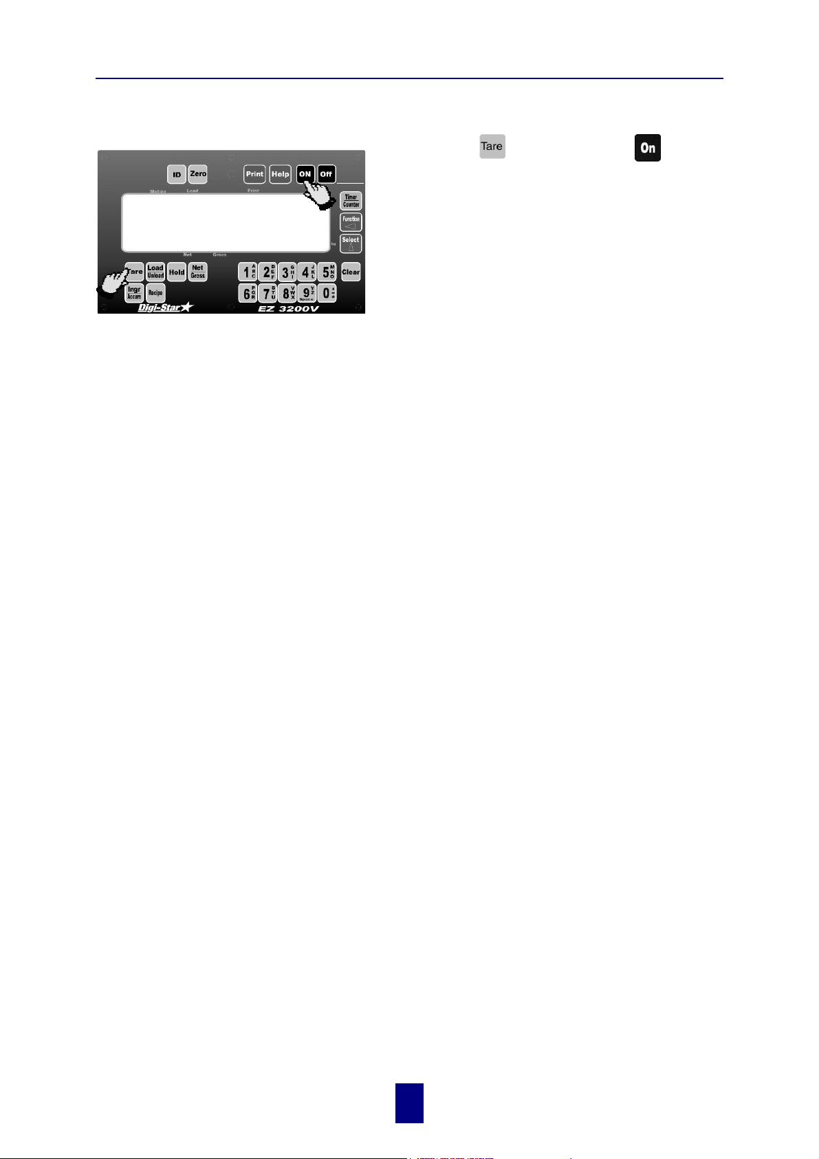
TO RETURN TO WEIGH MODE
1
To exit setup without changing any values, press
and hold the
key, then press the
key.
and
2
copyright - 10/24/2001
!
7
Page 11
Digi-Star Model EZ3200/EZ3200V/EZ3200V RC
5. Getting started
To operate the scale, first attach the scale's power cord to connector J901 and the loadcell cable to
connector J902 on the bottom panel of the scale.
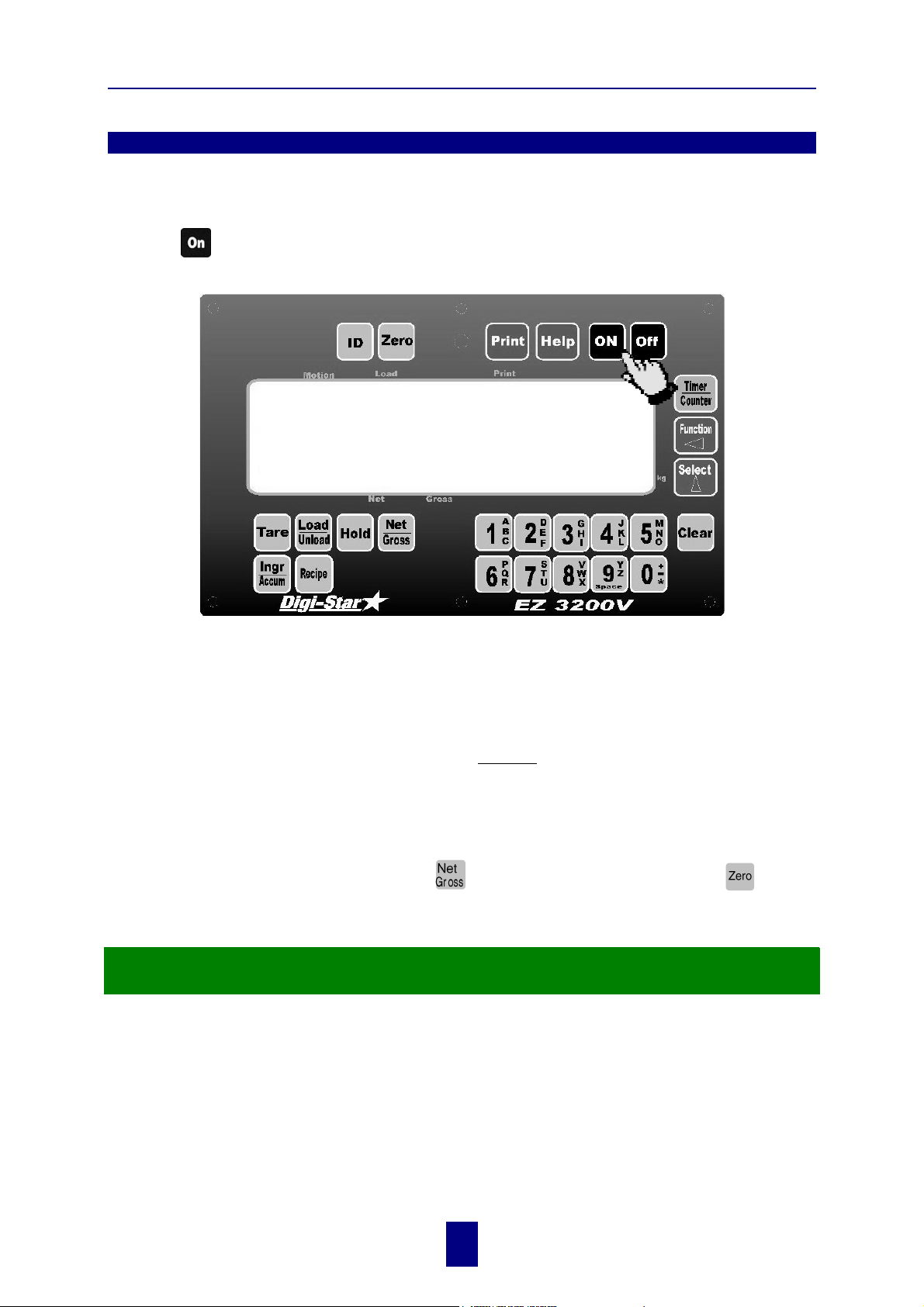
5. Getting started
Press the
key. A brief message is displayed (such as
HELLO
The scale enters the GROSS mode.
HELLO
).
A warm up period of ten to fifteen minutes provides the most accurate readings. If the scale is
holding a load for a long period of time (ex. overnight), the weight displayed may vary because of
zero shift created by changes in temperature. This does not affect the accuracy of the scale.
For example, if the system was loaded with 1000lbs, it might read 1200lbs the following day. The
change in temperature "zero shifted" the ZERO/BALANCE from 0 to 200lbs. When unloading the
scale, the display will count from 1200 to 200lbs for a total of 1000lbs.
After this warm up period, press and release
The word
is displayed to show completion of the ZERO/BALANCE step.
ZERO
. Then, within three seconds, press
.
Now the scale is ready to weigh!
copyright - 10/24/2001
!
8
Page 12
Digi-Star Model EZ3200/EZ3200V/EZ3200V RC
6. System operation
EZ3200 V shown - EZ3200 and ES3200V RC operations are the same.
!
LB and KG annunciators are located along right hand edge of the 3200V display.
!
6. System operation
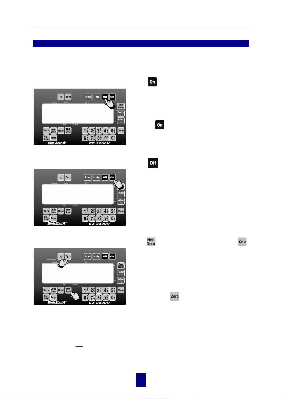
TURNING ON THE SCALE
HELLO
TURNING OFF THE SCALE
Press
A brief message will be displayed (such as
The scale then enters the GROSS weighing mode.
GROSS mode displays the weight change since the
unit was last ZERO/BALANCED.
Pressing
operation starts the self test.
Press .
.
a second time during normal system
HELLO
).
TO ZERO BALANCE THE SCALE
and
zero
If the supply power is below the low battery threshold (10.5 Volts), the message
LOW BATTERY VOLTAGE
(approx. every five seconds) to alert the operator of the low battery condition.
Loss of power does not affect the Zero/Balance or Setup/Calibration values.
copyright - 10/24/2001
!
is displayed. The message
Press and then within three seconds, press .
The [Zero] key will "balance off" empty trailer, bin,
or platform weight.
The message
the step and the scale is placed in the GROSS
mode.
Pressing only
ZERO/BALANCE PRESS NET/ GROSS - THEN ZERO
displayed.
will be periodically shown on the display
LO BAT
9
is displayed to show completion of
ZERO
will cause the message:
TO
to be
CANNOT balance --
Page 13
Digi-Star Model EZ3200/EZ3200V/EZ3200V RC
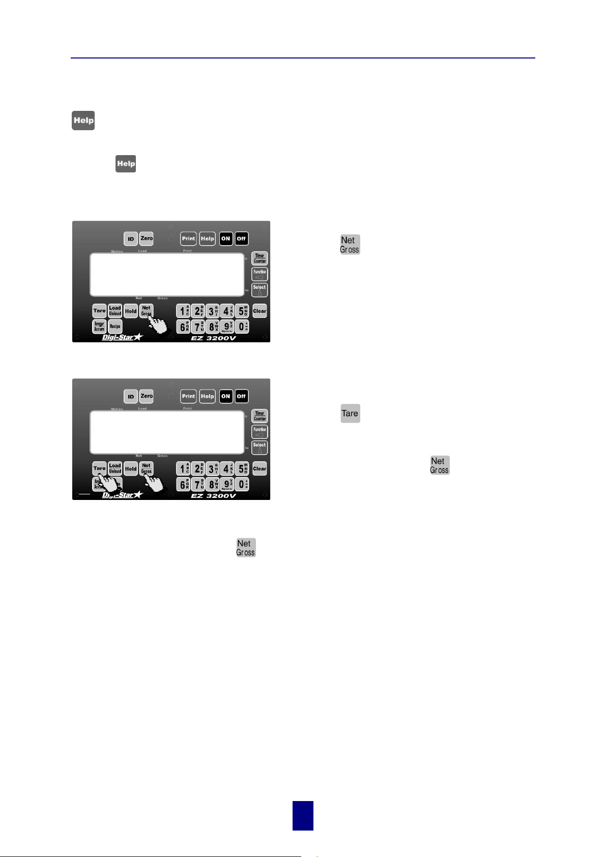
USING THE HELP KEY
provides additional information about the weighing modes, setup/calibration, and recipe
programming.
6. System operation
Pressing
TO SELECT GROSS MODE
TO SELECT NET MODE
while displaying weight will display information about the last key pressed.
9850
%
%
0
!
Gross Mode displays the weight change since
the unit was last Zero/Balanced.
1. Press
!
The scale is in Gross Mode if there is a flashing
arrow (% ) pointing toward the word Gross, next to
the display.
Net Mode displays the weight change after a
Tare has been performed. Tare creates a
temporary zero at that weight value.
1. Press
enter the Net Mode.
or
.
to set a temporary "zero" point and
2. If in Gross Mode, press
or
3. If in Load/Unload Mode, press
If the Tare Function has not been previously performed, the unit will stay in the Gross Mode
!
and the message
The scale is in Net Mode if there is a flashing arrow (% ) pointing toward the word Net, just
above the [Hold] and [Net/Gross] keys.
2/31
FOR NET MODE PRESS TARE
two times to place the scale in Net Mode.
will scroll across the display.
or
key is an alternating action key. If the scale is
in the Gross Mode, pressing the [Net/Gross]
key will place it in the Net Mode. If the scale
is in the Net Mode, pressing the [Net/Gross]
key will place it in the Gross Mode.
.The [Net/Gross]
copyright - 10/24/2001
!
10
Page 14
Digi-Star Model EZ3200/EZ3200V/EZ3200V RC
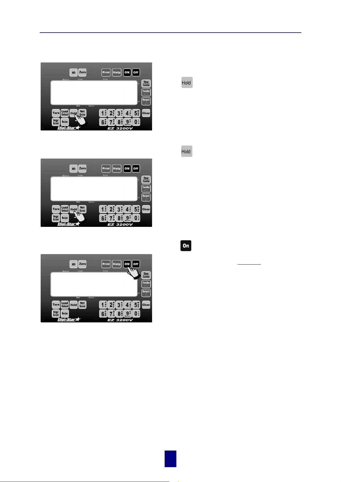
TO SELECT HOLD MODE Hold Mode prevents the displayed weight
from changing due to “zero shift” while
moving the scale.
6. System operation
hold
TO EXIT HOLD MODE
9850
%
TO CANCEL HOLD MODE
!
Press
the Hold Mode.
!
The scale is in Hold Mode if the word
flashing on the display and the flashing
is only displayed for a brief time.
Press .
At this time the scale reactivates and adjusts the
Zero/Balance to maintain the gross weight
displayed. Small changes in weight can occur while
moving the scale system to new locations for
loading or unloading. This change is called "zero
shift" and is due to several factors including terrain
changes and mechanical stresses.
Press .
to "hold" the displayed weight and enter
is
HOLD
hold weight
9850
%
!
Cancelling the Hold Mode prevents the scale from
adjusting the Zero/Balance and returns the system
to the normal weighing mode.
Use this if weight is accidentally added while scale
is still in Hold Mode.
copyright - 10/24/2001
!
11
Page 15

Digi-Star Model EZ3200/EZ3200V/EZ3200V RC
t
6. System operation
TO ENTER A PRESET
prese
2
293
%
2x
4
5
4
1 1
!
A Preset is a weight amount that can be set in
the scale.
1. Use the numeric keypad to enter the desired
preset weight value.
2. Press
amount to the nearest display count size.
3. Add or remove weight. The scale alternates
between flashing the word
amount, until 5 percent of the preset weight is
either loaded or unloaded.
4. While weight is being added or removed, press
press
Unload Mode.
5. To display weight added since the preset was
entered, press
Mode or one time if in Gross Mode.
. The indicator will round the preset
PRESET
and the preset
to display weight data in Gross Mode or,
to display weight data in Load/
two times if in Load/Unload
Once the preset has been entered, the display shows the weight data in one of three different
Display Modes:
1. Gross Mode
As ingredients are loaded, the weight display counts upward toward the preset value. As
ingredients are unloaded the weight display counts down to the preset value.
2. Load/Unload Mode
Display the amount remaining to be loaded or unloaded. As ingredients are loaded or
unloaded, the display counts down from the entered preset weight until it reaches zero.
3. Net Mode
Display the weight added since the preset has been entered. As ingredients are loaded, the
weight display counts upward, as they are unloaded the weight display counts down.
Switching between these display modes is possible at any time.
Before the preset weight is reached, the pre-alarm is activated. This causes the preset display
annunciator, the front panel alarm light, the output relay, and the alarm horn all to pulse in
sequence with the alarm light. A pre-alarm provides an early warning before reaching the preset.
Set the pre-alarm value to 0 (zero) to prevent the alarm output from pulsing. See page 15: To
change the pre-alarm value.
Once the preset weight amount has been added or removed, the scale will activate an alarm. The
front panel alarm light, the output relay, the preset display annunciator, and the alarm horn will
all be held ON. See page 13: To clear the preset alarm.
12
copyright - 10/24/2001
!
Page 16

Digi-Star Model EZ3200/EZ3200V/EZ3200V RC
6. System operation
TO CLEAR THE PRESET ALARM
2
0
TO CLEAR THE PRESET ALARM USING THE TR OPTION
If you are reloading a preset amount and the preset alarm is activated, the alarm can be cleared
using the Remote Enter Preset Feature.
This feature is set in the Long Form Setup by setting Remote Input to
using the handheld TR (Transmitter/Receiver) option or by momentarily connecting the Remote
Input line in the power cord to 0.0 Vdc (Ground).
Using the Remote Zero feature of the TR option or Remote Input line in the power cord will also
clear the preset.
1. Press once to clear the preset alarm and
re-enter a new preset weight using the numeric
keypad.
(2×)
3
1
2. Press
the preset.
3. Press
return to Net Mode. This sets the display to
(zero) and returns the scale to Net Mode.
once to print the weight and clear
twice to clear the preset alarm and
. It is activated by
PRESET
0
copyright - 10/24/2001
!
13
Page 17

Digi-Star Model EZ3200/EZ3200V/EZ3200V RC
6. System operation
TO PRELOAD A TARE VALUE
1
20
1/2
and
The Preload Tare Feature (PRETAR) is useful for
weighing containers after they have already been
loaded. If the weight of the container is known, a
Tare Weight is preloaded in the scale and only the
2
4
Net Weight is displayed.
1. Balance the indicator (
2
2. Make sure the Preload Tare setting is set to ON
(Long Form Setup ! Menu 4).
TO ENTER MENU 4 OF THE LONG FORM SETUP
- Press and hold
- Press four times to select Menu 4.
- Press
3. Press to set the Pretar Option to ON.
4. Press
repeatedly until PRETAR is displayed.
to store the setting.
and then press
and
).
.
pretar
5
5000
8
7
5. Press and hold
3
return to normal Weighing Mode.
6. Add weight to the container.
7. Using the numeric keypad, enter the known
weight value of the unloaded container.
8. Press .
The following example demonstrates a feed wagon
on a platform scale:
a) Balance the scale (
b) Weigh and record the weight of the unloaded
wagon.
c) Pull the wagon off the scale and load the wagon.
7
d) Using the numeric keypad, enter the known
wagon's weight in the Indicator.
e) Place loaded wagon back on the scale to see the
net weight.
The Tare Weight can also be automatically printed
by setting ta rea p (Tare Auto-Print) to
of the Long Form Setup.
and then press to
and
).
ON
in Menu 2
! copyright - 10/24/2001
TO ENTER MENU 2 OF THE LONG FORM SETUP
- Press and hold
- Press two times to select Menu 2.
- Press
14
repeatedly until tarea p is displayed.
and then press
.
Page 18

Digi-Star Model EZ3200/EZ3200V/EZ3200V RC
6. System operation
TO USE THE PRE-ALARM
100
TO CHANGE THE PRE-ALARM VALUE
3/6
p mthd
5
5
The Pre-Alarm feature is an "early warning" for
the preset. For example, if the Pre-Alarm is set for
Weight with a value of 100 and the preset is 1000,
the preset alarm will flash during the last 100
lbs/kgs of the preset. The Pre-Alarm can also be set
to activate at a percentage of the preset instead of
a specific weight value. The alarms are continuous
once the preset is active. A Pre-Alarm provides an
early warning before reaching the preset which
allows the operator to be more accurate.
1. Go to Menu 4 of the Long Form Setup and
locate the P-MTHD Feature (see page 14: To
enter the Long Form Setup).
2
4
2. Press
indicator will flash the CAL annunciator.
3. Press
Feature (
4. Press
The [Clear] key erases one digit at a time.
Continue to press the [Clear] key until 0 (zero)
is displayed.
to select either
to store the setting. The Pre-Alarm
) is displayed next.
p-alm
to erase the current weight value.
weight
or
percnt
. The
5. Use the numeric keypad to enter a Pre-Alarm
Weight.
"""""!"
prevent the alarm output from pulsing!
6. Press
7. Press and hold
Set the pre-alarm value to 0 (zero) to
to store the setting.
and then press to
return to normal Weighing Mode.
copyright - 10/24/2001
!
15
Page 19

Digi-Star Model EZ3200/EZ3200V/EZ3200V RC
6. System operation
TO START THE MIX TIMER
or
3
3
00:01:44
2
3. When the correct time has been entered or if the number displayed is acceptable, press
or
The display now reads HOURS, MINUTES, and SECONDS (HH:MM:SS), separated by colons
that flash every second.
to set the time and start the Mix Timer.
00:01:43
There are two ways to start the Mix Timer.
Method 1
1. Press
1
2. Press the
2
2
displayed value. The [Select] key increments
the "flashing" digit and the [Function] key
selects which digit of the display is flashing.
Method 2
1. Use the numeric keypad to enter the amount of
time.
2. Press
Timer. The display now reads HOURS,
MINUTES, and SECONDS (HH:MM:SS),
separated by colons that flash every second.
to see the time currently set.
and keys to change the
to enter the time and start the Mix
1
TO CLEAR THE MIX TIMER
9850
%
TO RESTART THE MIX TIMER
00:01:44
1
Press either , or to select the
amount of time.
or
The scale clears the mix timer alarms and enters
the Weighing Mode.
!
Press twice without entering a numeric value
to start the mix timer using the time previously
entered.
2×
copyright - 10/24/2001
!
16
Page 20

Digi-Star Model EZ3200/EZ3200V/EZ3200V RC
6. System operation
TO START THE ROTATION COUNTER
or
3
3
25
2
3. When the correct count has been entered or if the number displayed is acceptable, press
or
The display now reads
annunciator will flash when pulses from the Rotation Sensor are detected.
to set the count and start the Rotation Counter.
, showing the number of rotations remaining. The Motion
REV XX
REV 25
1
1
There are two ways to start the Rotation Counter.
Method 1
1. Press
1
2
2
set.
2. Press the and keys to change the
displayed value. The [Select] key increments
the "flashing" digit and the [Function] key
selects which digit of the display is flashing.
Method 2
1. Use the numeric keypad to enter the number of
rotations to count.
2. Press
Rotation Counter. The display now reads
, showing the number of rotations remaining.
XX
The Motion annunciator will flash when pulses
from the Rotation Sensor are detected.
to see the rotation count currently
to enter the count and start the
REV
TO CLEAR THE ROTATION COUNTER
or
Rev -4
TO RESTART THE ROTATION COUNTER
25
Press either ,
The scale clears the Rotation Counter alarms and
enters the Weighing Mode. The Rotation Counter
will continue to count rotations past 0 (
negative numbers) until it is cleared.
Press twice without entering a numeric value
to start the Rotation Counter using the count
previously entered.
2×
,
or
.
REV -4
,
copyright - 10/24/2001
!
17
Page 21

Digi-Star Model EZ3200/EZ3200V/EZ3200V RC
6. System operation
PROGRAMMING RECIPES
There are three different methods for programming recipes:
1 - Amount per Animal
2 - Percent (%) per Load
3 - Amount per Load
Recipes programmed in one method will not be converted when a new entry method is
!
selected. To convert a recipe to a new method, erase and then re-program the recipe. See
page 20: To change the entry method.
Entry Method #1 - Amount per Animal
Allows entry of ingredient amounts required for feeding one animal. The scale calculates the
preset amounts required for each ingredient.
Example:
A recipe had been programmed for 18lbs of haylage and 16lbs of shell corn for one
animal. The recipe was then loaded for 100 animals. The scale calculated presets for
1800lbs of haylage and 1600lbs of shell corn.
Entry Method #2 - Percent (%) per Load/Animal.
Allows entry of ingredient amounts in percentages (%).The scale calculates the preset amounts
required for each ingredient.
Example:
A recipe had been programmed with 55% of haylage and 45% of shell corn. The recipe
TOTAM T
was then loaded for a
of 10,000lbs. The scale calculated presets for 5500lbs of
haylage and 4500lbs of shell corn.
Entry Method #3 - Amount per Load.
Allows entry of ingredient amounts required per load..
Example:
A recipe had been programmed with 5500lbs of haylage and 4500lbs of shell corn. The
recipe was then loaded for a
TOTAMT
of 10,000lbs. The scale calculated presets for
5500lbs of haylage and 4500lbs of shell corn. This same recipe could have been
changed the
to 9,000lbs and the scale would have calculated presets for 4950lbs
TOTAMT
haylage and 4050lbs of shell corn. See Appendix 2.
copyright - 10/24/2001
!
18
Page 22

Digi-Star Model EZ3200/EZ3200V/EZ3200V RC
y
g
6. System operation
TO PROGRAM A NEW RECIPE
progrm
and
1
rec- _ _
3
4
Before programming a new recipe:
"
Set the desired entry method (see page 20: To
change the entry method).
1
3
"
Rename ingredients as needed (see page 29:
To rename ingredients).
1. Press and hold
Continue holding both keys until the indicator
beeps and the scale displays the message
.
progrm
The scale then displays either the first recipe
number programmed
a recipe number can be entered.
2. Press .
3. Use the numeric keypad to select the recipe
number.
4. Press
The EZ3200 then displays a message indicating
the entry method to be used:
2
-
enter values in amount per Animal
-
Enter values in percent per Load
-
Enter values in Amount per Load
to enter the recipe number.
and then press .
REC-01
or
REC-
indicating that
ing-_ _
6
The ingredient name (e.g.
ingredient amount is displayed-
The first two digits,
amount for this ingredient.
corn- 1
YY
represent the ingredient number. The last four digits,
The message
following the entry method message.
5. Use the numeric ke
in
redient number. See Appendix 1 for
ingredient look up table with alpha names.
6. Press
5
5
) will be displayed followed by
YY:XXXX
(e.g.
!
Ingredient numbers do not have to be in
sequence.
01: 5.00).
.
ING-__
AMOUNT
is displayed immediately
pad to select the
. Next the prompt for the
XXXX
represent the
19
copyright - 10/24/2001
!
Page 23

Digi-Star Model EZ3200/EZ3200V/EZ3200V RC
g
7. Use the numeric keypad to select the four digit
8. Press
6. System operation
ingredient value.
to enter the value.
stored
12
8
10
TO CHANGE THE ENTRY METHOD
7
TOTAL
STORED
value
E
The scale will display the message
indicating that the ingredient has been saved into
non-volatile memory.
7
9. Continue steps 5 throu
ingredients have been entered.
10. Press
will now calculate and display the
of the recipe.
11. Repeat steps 1 trough 10 until all recipes have
been programmed.
12. Press
Mode and enter Weighing Modes.
1. In Menu 4 of the Long Form Setup, select
. (see page 14: To enter the Long Form
MTHD
Setup).
to complete the recipe. The scale
to exit the Recipe Programming
h 8 until all
E-mthd
4
2. Press
CAL annunciator and display the message
followed by the number 1, 2 or 3.
MTHD
3. Press
Entry Method.
1 = Amount per Animal
2 = Percent (%) per Load
3 = Amount per Load
4. Press
5. Press and hold
return to normal Weighing Mode.
2/3
1
. The indicator will beep, flash the
E-
again if you want to change the
to sore the setting.
and then press to
copyright - 10/24/2001
!
20
Page 24

Digi-Star Model EZ3200/EZ3200V/EZ3200V RC
y
x
6. System operation
TO EDIT A RECIPE
rec- _ _
and
rec- 12
12
Press and hold
Continue holding both keys until the indicator
beeps and the scale displays the message
The scale then displays the first recipe number
programmed
methods to select the recipe to edit:
Method 1
1. Press
displayed.
2. Press
method 2 below.
Method 2
and then press
REC-XX
. Use one of the following
until the desired recipe number is
to edit this recipe. Go to step 4 of
.
PROGRM
.
enter va
2
3
2
yy:xxx
8
6
5
1. Press
2. Use the numeric ke
number.
3. Press
The EZ3200 will then display a message indicating
1
the "entry method" to be used:
-
enter values in amount per Animal
-
Enter values in percent per Load
-
Enter values in Amount per Load
4. The ingredient name will be displayed followed
by
AMOUNT
amount is displayed-
5. Enter the new amount.
7
5
6. Press
ingredient of the recipe.
7. Press
the four digit ingredient value.
.
pad to select the recipe
to enter the recipe number.
. Next the prompt for the ingredient
.
YY:XXXX
to advance the scale to the next
and use numeric keypad to select
copyright - 10/24/2001
!
8. Press
21
to enter the value.
Page 25

Digi-Star Model EZ3200/EZ3200V/EZ3200V RC
6. System operation
9. The scale will display the message
indicating that the ingredient has been saved
into non-volatile memory. Non volatile memory
is a special type of memory that allows the
stored
12
11
Ingredient amounts can be changed, but to add ingredients to a recipe, first erase that
!
recipe and then re-program the recipe.
TO ERASE A RECIPE
1
power to be removed from the scale without
losing any of the recipes.
10. Continue steps 5 through 8 until the desired
changes have been made.
11. Press
will now calculate and display the
of the recipe.
12. Press
Mode and enter weighing mode.
1. Press and hold
Continue holding both keys until the indicator
beeps and the scale displays the message
PROGRM
number programmed
to complete the recipe. The scale
to exit the Recipe Programming
and then press
. The scale then displays the first recipe
REC-XX
.
total
store d
value
.
progrm
and
1
5
3
rec-11
6
2
2. Press
displayed or,
press and use numeric keypad to enter the
recipe number to be erased (e.g.
3. Press and hold
the recipe.
4. Continue holding both keys until the indicator
beeps and displays the message
PRINTING RECIPES
press
2
5. Press
RECipe 11 ERASED
6. Press
Mode and enter the Weighing Mode.
7. To erase all recipes, continue steps 1 through 4
until all the recipes have been erased.
4
3
and
or
until the desired recipe number is
).
rec-11
, then press to erase
PLEASE WAIT -
. To reprint the recipe, simply
.
to erase the recipe. The message
will be displayed.
to exit the Recipe Programming
copyright - 10/24/2001
!
22
Page 26

Digi-Star Model EZ3200/EZ3200V/EZ3200V RC
6. System operation
TO PRINT A SINGLE RECIPE
2
REC-01
1/3
TO PRINT ALL RECIPES
2/3
REC-01
or
4 4
1/3
1. Press . The scale will display the first
recipe in memory.
2. Press
This prints the ingredients of this recipe.
3. Press
1. Press to review recipes.
2. Press
currently displayed.
3. Press
in the recipe memory will be printed.
4. Press
until all recipes have been displayed.
.
to advance onto the next recipe.
. This prints the recipe number
again. All recipes currently residing
or to exit, or continue to press
copyright - 10/24/2001
!
23
Page 27

Digi-Star Model EZ3200/EZ3200V/EZ3200V RC
USING THE AUTO ADVANCE FEATURE
The auto advance feature allows for hands free operation of programmed recipes. When the auto
advance feature is activated, the indicator automatically prints and advances to the next
ingredient once the Motion, Tolerance, and Delay Time requirements have been met. Motion,
tolerance, and delay time requirements are explained below.
The Tolerance feature is a “tolerance window” for the preset ingredient during batching. For
example, if the tolerance is set to 5% and the preset is 1000, the “tolerance window” is ±50. The
scale is in the “tolerance window” when the display is between 50 and -50.
The auto-advance circuitry of the recipe function activates the Delay Time counter while the
weight is in the tolerance window. The Delay Time allows the operator to slightly "under or over
shoot" an ingredient amount and still automatically advance to the next ingredient. The autoadvance circuitry resets the Delay Time counter every time the weight moves out of the tolerance
window. If enabled, Motion Detection also resets the Delay Time Counter.
6. System operation
If the tolerance for that ingredient is exceeded, the message
weight value. If this occurs, the scale will not auto-advance until the excess weight is removed.
If the operator determines that the additional weight for that ingredient is acceptable, pressing
or
If the tolerance is set to
been loaded regardless of any additional weight.
TO CHANGE THE TOLERANCE
will advance to the next ingredient.
OFF
, the scale will always auto-advance after the ingredient amount has
3
toler
2
1. Go to Menu 4 of the Long Form Setup and
choose
Form Setup).
2. Press
percentage) that an ingredient can be
under/over-loaded and still automatically
advance.
Tolerance Percentage Settings
OFF, 0.5, 1, 2, 3, 4, 5, 7,
!"
Set to
ingredient amount has been reached.
OVER
is displayed alternately with the
TOLER
(see page 14: To enter the Long
to choose the amount (by
or
10
to always advance after the
OFF
copyright - 10/24/2001
!
3. Press
4. Press and hold
return to normal Weighing Mode.
24
to store the setting.
and then press to
Page 28

Digi-Star Model EZ3200/EZ3200V/EZ3200V RC
t
USING DELAY TIME
The Delay Time Feature allows an operator to select the amount of time the scale should wait
before automatically advancing to the next ingredient of the recipe. This helps insure accuracy
for the ingredient amount. For example, if the delay time is set to 10 (seconds) and the preset
alarms are activated continuously, the auto-advance circuitry starts the Delay time Counter. If
the preset de-activates, the delay time counter is reset, therefore assuring that the preset weight
amount has to be met for the total delay time amount.
6. System operation
Setting Delay Time to
weight.
If loading a batch using a recipe,
next ingredient. See page 25: To load a batch using a recipe.
TO CHANGE THE DELAY TIME
MANUAL
prevents the scale from EVER auto-advancing, regardless of the
or
3
must be pressed twice to advance the recipe to the
1. Go to Menu 4 of the Long Form Setup and
select
Form Setup).
2. Press
to wait before automatically advancing.
DELAY
delay
2
Delay Time Selections in Seconds
MANUAL, 1, 2, 3, 5, 7, 10, 20, 30,
!"
Set to
after the ingredient amount has been
reached.
3. Press
(see page 14: To enter the Long
to select the delay time (in seconds)
or
60
to prevent automatic advance
MANUAL
to store the setting.
TO LOAD A BATCH USING A RECIPE
totam
2
1
4. Press and hold
return to normal Weighing Mode.
Either of the following methods can be used to load
a recipe while in the weighing modes:
Method 1
1. Press
displayed.
2. Press
(method 2).
until the desired recipe number is
to accept the recipe. Go to Step 4
and then press to
copyright - 10/24/2001
!
25
Page 29

Digi-Star Model EZ3200/EZ3200V/EZ3200V RC
t
Method 2
6. System operation
1. Press
totam
2
3
2
0
or
5
The display alternates between the first ingredient to be loaded and the ingredient amount to be
loaded. These two values are alternately displayed until 5% of the ingredient is either loaded or
unloaded.
6
6
2. Use the numeric keypad to select the recipe
number.
1
3. Press
4. The scale displays the message
and
either the Total amount to be loaded or the
Total amount of animals for that recipe.
To change the
is 0 (zero).
2x
5. Press
5
4
Press
6. Use the numeric keypad to enter a new total
amount value.
.
.
LOADING RECIPE XX
. The message
TOTAMT
press
totamt
to accept the amount displayed or,
twice to exit.
TOTAM T
until the value
represents
If the Delay Timer is set to manual (see page 25: To change the delay time), the recipe will not
automatically advance. The message
To manually advance to the next ingredient).
If using the Auto-advance feature (delay timer is not set to
Tolerance range (See page 24: To change the tolerance), the alarms will activate. This causes the
Delay timer to start and to automatically advance.
press ingr to advance to ingr-xx
will be displayed (see page 27
), and the weight is within the
manual
copyright - 10/24/2001
!
26
Page 30

Digi-Star Model EZ3200/EZ3200V/EZ3200V RC
6. System operation
TO MANUALLY ADVANCE TO THE
NEXT INGREDIENT
4665
4
1
2x
NOW THE RECIPE IS LOADED !
1. If loading a batch using a recipe and the Delay
Timer is set to manual, you must press
twice to advance to the next ingredient when
loading a recipe.
2. The first
ingredient and enters a Hold Weight Mode.
This allows the scale system to be moved to a
new location without affecting the weight
amount of the next ingredient. The second
press, advances the scale recipe to the next
ingredient!
3. After all ingredients have been loaded, the
scale displays the message:
= xxxxxxlb (xxxxxxkg).
4. Press
Mode.
press, completes the current
recipe complete total
to go back to normal Weighing
All ingredient amounts are automatically recalculated to provide the new total amount. This new
total will be used the next time this recipe is loaded.
TO REVIEW A RECIPE
1. Press . The scale displays the first recipe
loaded in memory.
until the desired recipe
to display each
3/4
rec-12
1/2
2. Continue pressing
number is displayed.
3. Press
recipe and the amounts for each ingredient
that should be loaded.
4. Continue pressing
ingredient.
5. Press
. This displays the ingredients of the
again to display the next recipe.
rec-13
6. Press
to exit the Recipe Review Mode.
5
copyright - 10/24/2001
!
6
27
Page 31

Digi-Star Model EZ3200/EZ3200V/EZ3200V RC
=
6. System operation
TO REVIEW INGREDIENT
ACCUMULATION
corn-3
3
1-3
TO PRINT ACCUMULATION FOR
ONE INGREDIENT
2
01:0050
Review ingredient accumulations (the total
amount of each ingredient that has been loaded) by
following these steps.
1. Press
ingredient used by the recipes and the total
amount that has been loaded/unloaded.
2. Continue to press
accumulations of other ingredients.
3. Continue to press
have been displayed or,
press to exit Ingredient Review Mode.
1. Press to review the ingredient
accumulations. The scale displays the first
ingredient used by the recipes and the total
amount that has been loaded/unloaded.
2. Press . This prints the total accumulation
for this ingredient.
. The scale displays the first
to display
until all ingredients
1/3
TO PRINT ACCUMULATION FOR
ALL INGREDIENTS
2/3
01:0050
4
1
3. Press
1. Press to review the ingredient
accumulations.
2. Press
for this ingredient.
3. Press
ingredients currently used in all recipes will be
printed.
4. Press
to advance onto the next ingredient.
. This prints the total accumulation
again. Accumulations for all
to return to weighing.
copyright - 10/24/2001
!
28
Page 32

Digi-Star Model EZ3200/EZ3200V/EZ3200V RC
6. System operation
TO PRINT THE INGREDIENT TABLE
2-4
01:0050
5
1
1. Press to review the ingredient
accumulations.
2. Press
for this ingredient.
3. Press again. Accumulations for all
ingredients currently used in all recipes will be
printed.
4. Press
Ingredient table will be printed. This shows
the names for all 99 ingredients in the table.
Ingredients not currently used by a recipe
print
5. Press
The ingredient table shows which ingredient name
will be displayed while load/unloading ingredients
during batching or feeding (see Appendix 1:
Ingredient names).
. This prints the total accumulation
a third time. Now the entire
unused
for their accumulation value
to return to weighing.
TO RENAME INGREDIENTS
progrm
and
1
corn-1
1
1. Enter Ingredient Program Mode by pressing
and holding
1
2
2. Continue holding both keys until the indicator
beeps and the scale displays the message
.
PROGRM
3. The scale then displays the first ingredient
number in the table
following methods to select the ingredient
name to edit:
Method 1
1. Press
is displayed.
2. Press
. Go to Step 3 of method 2 below.
and then pressing
ING-01
. Use one of the
until the desired ingredient number
.
copyright - 10/24/2001
!
29
Page 33

Digi-Star Model EZ3200/EZ3200V/EZ3200V RC
Method 2
1. Use the numeric keypad to enter the
6. System operation
ingredient number.
corn-1
1
2
1
5
barley-2
7
!""
A blank name " _" cannot be saved, instead the original name will be restored.
The ingredient names are saved into non-volatile memory. Non-volatile memory is a special type
of memory that allows the power to be removed from the scale without losing any of the
ingredient names.
4
4
2. Press
displayed:
3
3. Press
[Clear] key to delete the entire name.
4. Use the alpha-numeric keypad to enter the six
character/number ingredient name.
5. Press
to the next ingredient.
To cancel your changes and restore the
!
original name, simply press
. The ingredient name will be
CORN-1
.
to backspace or press & hold the
to store the new name and advance
.
6. Continue steps 2 through 5 until the desired changes have been made.
7. Press
TO ERASE ACCUMULATION FOR
ONE INGREDIENT
1
to exit the Ingredient programming mode and enter the weighing modes
1. Enter Ingredient Program Mode by pressing
ING-01
and holding
2. Continue holding both keys until the indicator
2
beeps and the scale displays the message
.
PROGRM
3. The scale then displays the first ingredient
number in the table
following methods to select the ingredient
name to erase:
Method 1
1. Press
is displayed. Go to step 4 of method 2 below.
and then pressing
until the desired ingredient number
ING-01
. Use one of the
.
copyright - 10/24/2001
!
30
Page 34

Digi-Star Model EZ3200/EZ3200V/EZ3200V RC
e
Method 2
6. System operation
4
3
corn-1
2
or
5
pleas
6
and
4
1
1
5
1. Use the numeric keypad to enter the
ingredient number to be erased.
2. Press
displayed-
3. Press
4. Press and hold
the recipe. Continue holding both keys until
the indicator beeps and displays the message
PLEASE WAIT - PRINTING ACCUMULATION VALUES
5. Press
accumulation value.
6. Press
mode and enter the weighing modes.
. The ingredient name will be
CORN-1
.
.
, then press to erase
.
to erase or
to exit the Ingredient programming
to re-print
TO ERASE THE ACCUMULATION
VALUES FOR ALL INGREDIENTS
To erase the accumulation values for ALL
ingredients, repeat steps 1 through 5 listed above,
but then repeat steps 3, 4 & 5 for the same
ingredient.
Press
Mode and return to Normal Weighing Mode.
to exit the Ingredient Programming
copyright - 10/24/2001
!
31
Page 35

Digi-Star Model EZ3200/EZ3200V/EZ3200V RC
7. Optional features
7. Optional features
Optional features are installed in the indicator if the corresponding keys are on the front panel or
if additional connectors are on the bottom panel.
REMOTE DISPLAY
A Remote Display is available for viewing weight data at convenient locations. The Remote
Display includes a visual alarm light which can be used with the TR option listed below.
TR: RADIO CONTROL OPERATION
The TR option allows the operator to remotely control the scale from a distance up to 100 feet
away (depending on the environment). The TR option allows the operator to perform TARE and
GROSS or “Ingredient Advance” functions.
PRINT WEIGHT DATA
Weight data can be sent to a printer by pressing the PRINT key. An auto-print feature can be
selected in Menu #2 of the Long Form Setup.
CLOCK OPTION
ID# OPTION
TO ENTER ID NUMBER
2/3
26
1
1
TO DISPLAY ID NUMBER
1
1. Use the numeric keypad to enter an
identification number.
2. Press
The identification number is also printed on
every weight printout. Printing automatically
clears the identification number so that a new
value can or must be entered.
3
3. The identification number can be cleared by
pressing
1. Press .
to enter the identification number.
and then pressing .
copyright - 10/24/2001
!
ID NO
32
Page 36

Digi-Star Model EZ3200/EZ3200V/EZ3200V RC
7. Optional features
TO USE FUNCTION & SELECT KEYS
HOLD
!"
maintains the selected operation until
The [Function] key provides additional features for
operating the scale. The [Function] key is similar
to the F1 key of a computer. It provides Help and
additional functionality. The [Select] key is used to
determine what operation will occur when the
[Function] key is pressed.
1/3
2/4
is used to determine what operation will
occur when
1. Press
the [Function] key.
2. Press
Continue to press the [Select] key until the
desired operation is displayed.
is pressed again.
is pressed.
to display the current operation of
to change the current operation.
3. Press
4. Press
For example, if the word
!
Rotation Counter. If the message M+ is displayed, then pressing the [Function] key will
cause the scale to perform the Memory Plus (M+) operation.
The [Function] key operation is stored in non-volatile memory. This allows the scale to
remember the operation of the [Function] key even when the unit is turned OFF.
Press the [Select] key once to display the operation currently assigned to the [Function] key.
at any time to perform the selected operation.
once to display the operation assigned to the [Function] key.
is displayed, then pressing the [Function] key will activate the
TIMER
copyright - 10/24/2001
!
33
Page 37

Digi-Star Model EZ3200/EZ3200V/EZ3200V RC
7. Optional features
TO ADD WEIGHT TO WEIGH
MEMORY
m+
RECALL WEIGH MEMORY
RM
1. Press until M+ is displayed. This assigns
the Memory Plus (M+) operation to
2. Press
option and this stores the new weight data in
memory.
2
1
1. Press until rm (Recall Memory) is
displayed.
2. Press
operation.
2
The weigh memory will be temporarily displayed.
1
to perform the Memory Plus (M+)
to perform the Recall Memory (RM)
.
PRINT WEIGH MEMORY (OPTION)
3
9850
CLEAR WEIGH MEMORY
CM
1. Press until rm (Recall Memory) is
displayed.
2. Press
2
3. Then press the
1
2
1
memory is still displayed.
The PRINT key causes the unit to print the weigh
memory and return to the normal weighing modes.
1. Press to assign the CM operation to the
[Function] key.
2. Press
operation.
to display the weigh memory.
key while the weigh
to perform this Clear Memory (CM)
copyright - 10/24/2001
!
34
Page 38

Digi-Star Model EZ3200/EZ3200V/EZ3200V RC
7. Optional features
WEIGH AVERAGING
3
1258
BLACK OUT
The Clock Option is required as part of the Black Out option. The Clock records the time,
!
date, and preset remaining before the power outage (blackout).
The Black Out option is a preset enhancement that maintains the “preset amount left to go” in
non-volatile, permanent memory. This insures that the correct weight can be delivered even after
a power outage.
1. Press to assign the RM operation to the
[Function] key.
2. Press
2×
2
1
perform the weigh averaging operation.
The
weigh memory will be displayed first. Then the
message
average weight value.
3. To print the average weight value, press
or number of weight values added to the
COUNT
AVERAG
while the average weight is still displayed.
twice within three seconds to
is displayed, followed by the
For example, a system loaded with 2000 lbs unloads a preset of 100 lbs. After unloading the first
500 lbs, a power outage occurs. When the power is restored and the scale turned back On, the
message
this time, press START on the control box (or press the NET/GROSS key on the indicator). This
loads the preset amount remaining before the black out (500 lbs in this example).
Pressing
POWER OUTAGE – PRESS START ON CONTROL BOX TO FINISH PRESET – CLEAR TO CANCEL MO/DA/UR 12:00A.
cancels the preset and the scale displays the GROSS weight.
At
copyright - 10/24/2001
!
35
Page 39

Digi-Star Model EZ3200/EZ3200V/EZ3200V RC
PULSED OUTPUT
!
The Clock Option is required as part of the Pulsed Output option.
The Pulsed Output option provides one output line to indicate decreasing weight.
Pulsed Output pulls the connected signal line to ground through a 330 Ohm resistor for 150 milliseconds every time the scale decreases one display count.
!"
1 Display Count = 1 Output Pulse
The scale will not pull the line to ground more than twice (2 times) a second – 2 Hz.
For example, if the weight decreased from 8000 lbs to 7500 lbs, using a display count of 10 lb
counts:
8000-7500=500 (lbs weight change)
500/10 (Display Count) = 50 Pulses
There would be 50 output pulses taking about 25 seconds to output all 50 pulses. In this
example, 7500 lbs represents the Gross Weight Reference Point. The scale resets the Gross
Weight Reference Point if the weight increases 100 or more pounds for at least one(1) minute. The
scale starts pulsing outputs as weight decreases from the new Gross Weight Reference Point.
7. Optional features
There are two (2) ways to “reset” or “abort” the internal pulse counter of the scale. Either Zero
Balance the scale or turn the scale OFF and back On again then press the [ZERO] key when the
scale shows the power outage message.
The Clock records the time, date, and Gross Weight Reference Point before the power outage.
When power is restored, the scale will display the message
PULSED OUTPUT – ZERO TO RESET MO/DA/YR 12:00A.
in the proper sequence.
This provides the opportunity to start other equipment
POWER OUTAGE – PRESS NET/GROSS TO CONTINUE
copyright - 10/24/2001
!
36
Page 40

Digi-Star Model EZ3200/EZ3200V/EZ3200V RC
APPENDIX 1: Ingredient names
APPENDIX 1: Ingredient names
This list shows the number and name of the ingredients as shipped from Digi-Star.
Each name can be changed. See the section To Rename Ingredients to change an
!
ingredient name.
INGR. NO. NAME INGR. NO. NAME INGR. NO. NAME
ING-01 CORN-1 ING-34 HYLG-4 ING-69 BUNK-9
ING-02 CORN-2 ING-35 HYLG-5 ING-70 MISC
ING-03 CORN-3 ING-36 HYLG-6 ING-71 MISC-1
ING-04 HAY ING-37 HYLG-7 ING-72 MISC-2
ING-05 HAY-1 ING-38 HYLG-8 ING-73 MISC-3
ING-06 HAY-2 ING-39 HYLG-9 ING-74 MISC-4
ING-07 HAY-3 ING-40 CSILAG ING-75 MISC-5
ING-08 BARLEY ING-41 CSLG-1 ING-76 MISC-6
ING-09 CANOLA ING-42 CSLG-2 ING-77 MISC-7
ING-10 COTTON ING-43 CSLG-3 ING-78 MISC-8
ING-11 DISTLR ING-44 CSLG-4 ING-79 MISC-9
ING-12 DRYPUL ING-45 CSLG-5 ING-80 PREMIX
ING-13 DRYBET ING-46 CSLG-6 ING-81 PRMIX1
ING-14 EARLAG ING-47 CSLG-7 ING-82 PRMIX2
ING-15 GRASS ING-48 CSLG-8 ING-83 PRMIX3
ING-16 MOLASS ING-49 CSLG-9 ING-84 PRMIX4
ING-17 WETPUL ING-50 SILAGE ING-85 PRMIX5
ING-18 SOY ING-51 SILO-1 ING-86 PRMIX6
ING-19 TALLO ING-54 SILO-4 ING-87 PRMIX7
ING-20 WATER ING-55 SILO-5 ING-88 PRMIX8
ING-21 TRACE1 ING-56 SILO-6 ING-89 PRMIX9
ING-22 TRACE2 ING-57 SILO-7 ING-90 MIXTUR
ING-23 TRACE3 ING-58 SILO-8 ING-91 MIX- 1
ING-24 TRACE4 ING-59 SILO-9 ING-92 MIX- 2
ING-25 TRACE5 ING-60 BUNKER ING-93 MIX- 3
ING-26 TRACE6 ING-61 BUNK-1 ING-94 MIX- 4
ING-27 TRACE7 ING-62 BUNK-2 ING-95 MIX- 5
ING-28 TRACE8 ING-63 BUNK-3 ING-96 MIX- 6
ING-29 TRACE9 ING-64 BUNK-4 ING-97 MIX- 7
ING-30 HAYLAG ING-65 BUNK-5 ING-98 MIX- 8
ING-31 HYLG-1 ING-66 BUNK-6 ING-99 MIX- 9
ING-32 HYLG-2 ING-67 BUNK-7
ING-33 HYLG-3 ING-68 BUNK-8
copyright - 10/24/2001
!
37
Page 41

Digi-Star Model EZ3200/EZ3200V/EZ3200V RC
APPENDIX 2: Examples
APPENDIX 2: Examples of programming recipes
These examples are shown to illustrate the three different program entry methods available.
Each method can be used to obtain the same results, the choice is yours. Note that Recipe #5
includes some of the same ingredients as Recipe #12, but are loaded in a different sequence to
illustrate the flexibility of programming to match actual loading sequence.
to program
recipe#12 program entry methods available (choose one)
ingredient
name
(1) Haylage 3 18.0 34.62 1800
(2) High Moisture Corn 9 10.0 19.23 1000
(3) Corn Silage 5 24.0 46.15 2400
Total 52 lbs
recipe#12
ingredient
name
(1) Haylage 3 1800 1800 1800
(2) High Moisture Corn 9 1000 1000 1000
(3) Corn Silage 5 2400 2400 2400
Total 5200
ingredient
number
ingredient
number
amt. per
animal
to load
amt. per
animal
enter # of
animals
100
animals
% per load
or
% per load
enter load
or
amount per
load
or
100.00
5200
amount per
load
accept 5200 or
size
5200 5200
5200
enter new size
or
5200
copyright - 10/24/2001
!
38
Page 42

Digi-Star Model EZ3200/EZ3200V/EZ3200V RC
APPENDIX 2: Examples
to program
recipe#5 program entry methods available (choose one)
ingredient
name
ingredient
number
amt. per
animal
% per load
amount per
load
(1) Corn Silage 5 15.0 37.50 1800
(2) Haylage 3 14.5 36.25 1740
or
or
(3) Soy Bean 10 2.3 5.75 276
(4) Cotton Seed Hulls 12 8.2
20.50
984
Total 40 lbs 100.00 4800
to load
recipe#5
ingredient
name
ingredient
number
amt. per
animal
enter # of
animals
120
animals
% per load
enter load
or
size
4800 4800
amount per
load
accept 4800 or
enter new size
or
(1) Corn Silage 5 1800 1800 1800
(2) Haylage 3 1740 1740 1740
(3) Soy Bean 10 276
276
276
(4) Cotton Seed Hulls 12 984 984 984
Total 4800 4800 4800
1: Amount per animal
Recipe programmed for one animal Ingredient presets for a 100 animal load
Haylage 18 lbs Haylage 1800 lbs
Corn Silage 10 lbs Corn Silage 1000 lbs
HM Shell Corn 16 lbs HM Shell Corn 1600 lbs
Soy Hulls 02 lbs Soy Hulls 200 lbs
Soybeans 06 lbs Soybeans 600 lbs
Total 52 lbs Total 5200 lbs
2: Percent per Load - %
Recipe programmed in % for total load Ingredient presets for 5200 lb load
Haylage 34.60% Haylage 1800 lbs
Corn Silage 19.23% Corn Silage 1000 lbs
HM Shell Corn 30.77% HM Shell Corn 1600 lbs
Soy Hulls 03.85% Soy Hulls 200 lbs
Soybeans 11.55% Soybeans 600 lbs
Total 100.00% Total 5200 lbs
copyright - 10/24/2001
!
39
Page 43

Digi-Star Model EZ3200/EZ3200V/EZ3200V RC
APPENDIX 2: Examples
3: Amount per load - lb/kg
Recipe programmed in total lbs/load Ingredient presets for 5200 lb load
Haylage 1800 lbs Haylage 1800 lbs
Corn Silage 1000 lbs Corn Silage 1000 lbs
HM Shell Corn 1600 lbs HM Shell Corn 1600 lbs
Soy Hulls 200 lbs Soy Hulls 200 lbs
Soybeans 600 lbs Soybeans 600 lbs
Total 5200 lbs Total 5200 lbs
copyright - 10/24/2001
!
40
Page 44

Digi-Star Model EZ3200/EZ3200V/EZ3200V RC
Annunciator 9-12-15-20
Auto Advance 24-26
Black out 35
Cable Connection 2
Changing the Pre-alarm 15
Changing the Recipe Entry Method 20
Clearing the Mix Timer 16
Clearing the Preset Alarm using TR option 13
Clearing the Rotation Counter 17
Clearing Weigh Averaging 35
Clearing Weigh Memory 34
Clock option 29
Connection indicator to other Load Cells 6
Delay Time 25
Delay Time - Changing 25
Delay Time - Setting 25
Editing a Recipe 21
Entering a Preset 12
Entering ID numbers 32
Example Recipes 38-39-40
Function Key 33
Getting Started 8
Gross Mode 10
Help Key 10
Hold Mode 10-11
Hold Mode - Cancelling 11
Hold Mode - Exiting 11
ID Number - Entering 32
Indicator Mounting 2
Ingredient Names 37
Ingredients - Erase accumulation for all ingredients 31
Ingredients - Erase accumulation for one ingredient 30
Ingredients - Manually advance 27
Ingredients - Print accumulation for all i n gredients 28
Ingredients - Print accumulation for one ingredient 28
Ingredients - Print ingredient table 29
Ingredients - Review accumulations 28
Lightning Protection 3
Load Cell Connections 3
Loading a Batch using a Recipe 25
Matching EZ scales t o othe r s cales 5
Mix Timer 16
Mix Timer - Clearing 16
Mix Timer - Restarting 16
Mix Timer - Starting 16
Net Mode 10
Optional features 32
Optional features - Clock option 32
Optional features - ID# option 32
Optional features - Print Weight Data 34
Optional features - Remote Displa 32
Optional features - TR Radio Control 32
P-ALM 15
Power Connection 2
Pre-Alarm 15
Pre-Alarm - Changing 15
Pre-Alarm - Clear 15
INDEX
Page 45

Digi-Star Model EZ3200/EZ3200V/EZ3200V RC
Preset 12
Preset Alarm - Clear using the TR option 13
PRETAR 14
Printing a Single Recipe 23
Printing All Recipes 23
Printing Ingredient table 29
Printing Weigh Memory 34
Programming a new recipe 19
Programming Recipes 18
Pulsed output 36
Recalling Weigh Memory 34
Recipe - Editing 21
Recipe - Examples 38-39-40
Recipe - Loading a batch 25
Recipe - Manually advance to next ingredient 27
Recipe - Printing a single reci pe 23
Recipe - Printing all 23
Recipe - Programming a new recipe 19
Recipe - Programming recipes 18
Recipe - Reviewing 27
Recipe Entry Methods 18
Recipe Entry Methods - Amount per Animal 18
Recipe Entry Methods - Amount per Load 18
Recipe Entry Methods - Changing 20
Recipe Entry Methods - Percent per Load/Animal 18
Remote Alarm Connection 2
Remote Input Connection 2
Restarting the Mix Timer 16
Restarting the Rotation Counter 17
Reviewing a Recipe 27
Reviewing Ingredient Accumulation 28
Rotation Counter - Clear in g 17
Rotation Counter - Restarting 17
Rotation Counter - Starting 17
Scale information sheet 5
Scale matching example 5
Select Key 33
Selftest - Running 4
Setup and Calibration Requirements 4
Setup and Calibration Requirements - Changing 4
Tare 10-14-32
Tolerance - Percentage settings 24
Tolerance Feature 24
Turning Off the Sca le 6
Turning On the Scale 6
Weigh Averaging 32
Weigh Memory - Add Weight 34
Weigh Memory - Clear 34
Weigh Memory - Print 34
Weigh Memory - Recall 34
Zero Balance 9-36
INDEX
 Loading...