

Page 1
H
EZ2500
Operators Manual
ELLO
Ft. Atkinson, Wisconsin USA
Panningen, The Netherlands
www.digi-star.com
D3895-US July 19, 2011
Page 2

EZ2500 User’s Manual D3895-US Rev A
Page 3
Table of Contents
TABLE OF CONTENTS
TECHNICAL SPECIFICATIONS ..................................................................... 1
SAFETY DURING USE ................................................................................... 2
Cleaning ....................................................................................................... 2
Charging Battery and Welding ..................................................................... 2
INDICATOR OVERVIEW ................................................................................ 3
OPERATION ................................................................................................... 5
Turn on Indicator .......................................................................................... 5
Zero Balance Indicator ................................................................................. 5
Tare and Net/Gross ..................................................................................... 5
Print Key....................................................................................................... 7
Timer Option ................................................................................................ 7
Using the M+, RM and CM Options ............................................................. 8
Printing Weight from Memory .................................................................... 10
Weight Averaging ....................................................................................... 10
Printing Average Weight ............................................................................ 11
OTHER FUNCTIONS .................................................................................... 12
Hold ............................................................................................................ 12
Using Dimmer Option ................................................................................. 12
Function and Select keys ........................................................................... 12
MENUS AND CALIBRATION ........................................................................ 13
Change Set up and Calibration Numbers .................................................. 16
INSTALLATION ............................................................................................. 17
Indicator Mounting ..................................................................................... 17
Cable Connection ...................................................................................... 18
Indicator Connection Diagram ................................................................... 18
Bottom Panel Cable Connections .............................................................. 18
Connect Load Cells to J-Box ..................................................................... 19
Load Cell Direction ..................................................................................... 19
OPTIONAL EQUIPMENT .............................................................................. 20
Remote Indicators ...................................................................................... 20
TROUBLESHOOTING .................................................................................. 21
All rights reserved. Reproduction of any part of this manual in any form whatsoever without Digi-Star’s express written
permission is forbidden. The contents of this manual are subject to change without notice. All efforts have been made to
assure the accuracy of the contents of this manual. However, should any errors be detected, Digi-Star would greatly
appreciate being informed of them. The above notwithstanding, Digi-Star can assume no responsibility for any errors in
this manual or their consequence.
© Copyright! 2008 Digi-Star, Fort Atkinson (U.S.A.).
D3895-US Rev A EZ2500 User’s Manual
Page 4

Table of Contents
EZ2500 User’s Manual D3895-US Rev A
Page 5
Technical Specifications
TECHNICAL SPECIFICATIONS
SIZE
10.25” long x 8.0” high x 2.7” wide
(260mm x 190mm x 70mm)
WEIGHT
2.7 lbs (1.2 Kg)
HELP MESSAGES
Context sensitive help messages in 10
languages
Long messages are scrolled
TRANSDUCER EXCITATION
8 volts D.C. Nominal
Capable of driving ten 350 Ohms transducers
Short circuit proof
TRANSDUCER SIGNAL
Compatible with transducers having full scale
indicator transfer characteristics greater than
0.25 mv/v
“AUTO RANGE”
(Selectable) To increase display counts
at weight values of 300 and 600 display counts.
CONNECTOR
AMP plastic weather resistant circular
connector. Gold contacts.
POWER REQUIREMENTS
10.5 to 16.0 V.D.C.
160 mA nominal with four 350Ω L.C.
SET UP AND CALIBRATION
Via front panel
GROSS RANGE
999,999 max.display
LOW BATTERY WARNING
Enabled at 10.5V nominal
POUND/KILOGRAM
Selectable
DISPLAY RESOLUTION
.01, .02, .05, .1, .2, .5, 1, 2, 5, 10, 20, 50, 100
DISPLAY UPDATE RATE
Selectable: 1, 2, 3, 4 times/sec.
MAX. DISPLAY RESOLUTION
Adjustable to 40,000 counts max.
ZERO TRACKING
Selectable, On/Off
SPAN ACCURACY
±(.1% + .005%/ °F) or (.1% + 0.009% °C) full scale ± 1
output count
MOTION DETECTION
Selectable, On/Off
ZERO ACCURACY
(.005%/ °F.) or (0.009% °C) full scale ±1 output count
for 0.5 mv/v transducer
ENVIRONMENTAL ENCLOSURE
IP65, IEC 529
WEIGH ALGORITHM
4 internally selectable digital filters to optimize
performance
(General, Slow, Fast and Lock-on)
HOLD MODE
Used in mobile applications to stabilize displayed
weight while moving the scale
NON-VOLATILE MEMORY
EEPROM for balance
OPERATING TEMP
-29°C to 60°C -20°F to 140°F
D3895-US Rev A EZ2500 User’s Manual 1
Page 6
Safety During Use
p
SAFETY DURING USE
Caution
Cleaning
Do not use running water (high pressure cleaners, hoses) to clean the
indicator.
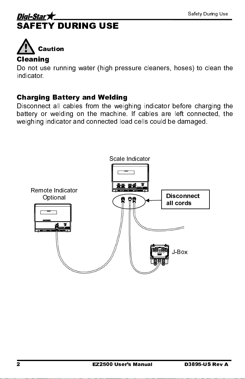
Charging Battery and Welding
Disconnect all cables from the weighing indicator before charging the
battery or welding on the machine. If cables are left connected, the
weighing indicator and connected load cells could be damaged.
Scale Indicator
Remote Indicator
O
tional
2 EZ2500 User’s Manual D3895-US Rev A
Disconnect
all cords
J-Box
Page 7
Indicator Overview
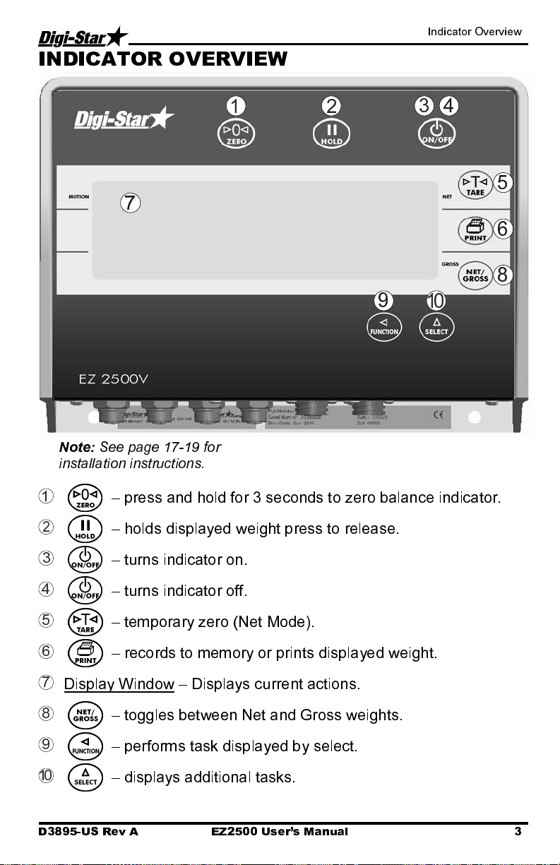
INDICATOR OVERVIEW
4
1
2
3
5
7
6
8
9
Note:
See page 17-19 for
installation instructions.
1
– press and hold for 3 seconds to zero balance indicator.
2
– holds displayed weight press to release.
3
– turns indicator on.
4
– turns indicator off.
5
– temporary zero (Net Mode).
6
– records to memory or prints displayed weight.
7
Display Window – Displays current actions.
10
8
– toggles between Net and Gross weights.
9
– performs task displayed by select.
10
– displays additional tasks.
D3895-US Rev A EZ2500 User’s Manual 3
Page 8
Indicator Overview
11
12
13
14
15
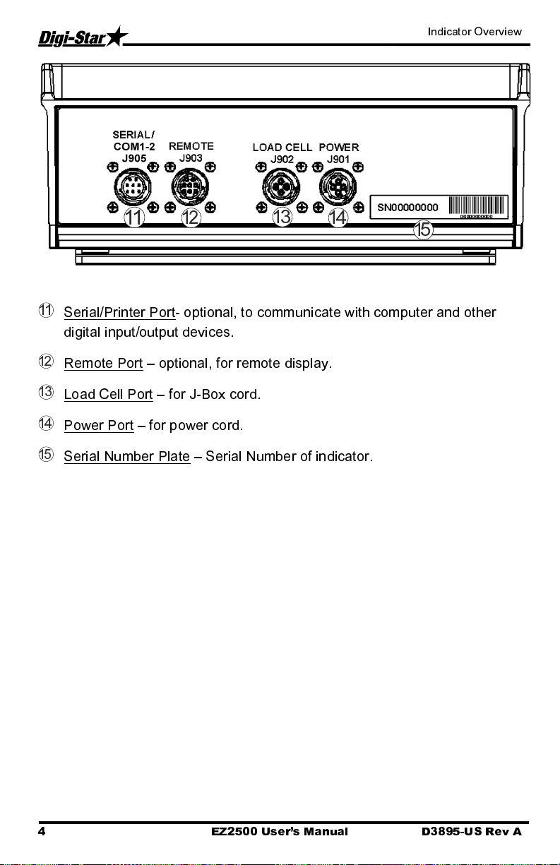
11
Serial/Printer Port- optional, to communicate with computer and other
digital input/output devices.
12
Remote Port
13
Load Cell Port – for J-Box cord.
14
Power Port – for power cord.
15
Serial Number Plate
– optional, for remote display.
– Serial Number of indicator.
4 EZ2500 User’s Manual D3895-US Rev A
Page 9

Operation
OPERATION
Turn on Indicator
HELLO
Zero Balance Indicator
1
1
0
2
Tare and Net/Gross
Tare is a temporary zero (Net Weight)
to display total weight (Gross Weight)
Press .
1
1. Press .
1. Press and hold for 3 seconds
to zero balance indicator.
2. Flashing arrow points to gross next
to the display window, indicator
ready to weigh.
1. Weight displayed, press sets
zero weight.
4000
D3895-US Rev A EZ2500 User’s Manual 5
Page 10

Operation
2
0
3
300
4300
4
2. Pressing displays zero weight
and flashing arrow on side of
display points to NET.
3. Add more weight.
4. To know total of original weight of
4000 pounds plus added 300
pounds, press to show 4300
pounds, flashing arrow points
GROSS.
5. Press 300 pounds displayed
flashing arrow points NET.
300
5
6 EZ2500 User’s Manual D3895-US Rev A
Page 11

Operation
Print Key
Note:
Optional serial port must be
installed for printing.
4300
Timer Option
Stopwatch for mixing time.
TIMER
1
00:00:00
1
1. Press . Indicator sends data to
printer or PC.
Weight
1. Repeatedly press until
is displayed.
1. Press to displays hours,
minutes and seconds (hh:mm:ss).
4300 LB GR
Gross (GR) or
Net (NET)
TIMER
1
D3895-US Rev A EZ2500 User’s Manual 7
Page 12

Operation
4
00:04:00
3
1. Repeatedly press moves
flashing digit left.
2. Repeatedly press changes
number.
3. Press to start timer.
1
Using the M+, RM and CM
Options
Use these options to weigh truck or
wagon one axle at a time.
1
500
M+
2
RM 500
4. When timer reaches zero
press to clear timer.
2
1. Add weight on scale. Example: 500
pounds.
2. Repeatedly press until
displayed.
3. Press
briefly displayed 500 pounds added
to indicator memory and indicator in
gross weight mode.
500
pounds and
M+
RM
is
3
8 EZ2500 User’s Manual D3895-US Rev A
Page 13

Operation
4
I000
M+
5
RM I500
6
9
4. Put another weight on scale.
Example: 1000 pounds.
5. Repeatedly press until
displayed.
6. Press indicator add 1000
pounds to 500 pounds in memory
and
RM
flashes.
7. Repeatedly press until
displayed.
8. Press .
M+
RM
is
is
I500
8
9. Total of both weights,1500 pounds,
display, indicator switches to gross
weight mode.
7
D3895-US Rev A EZ2500 User’s Manual 9
Page 14
Operation
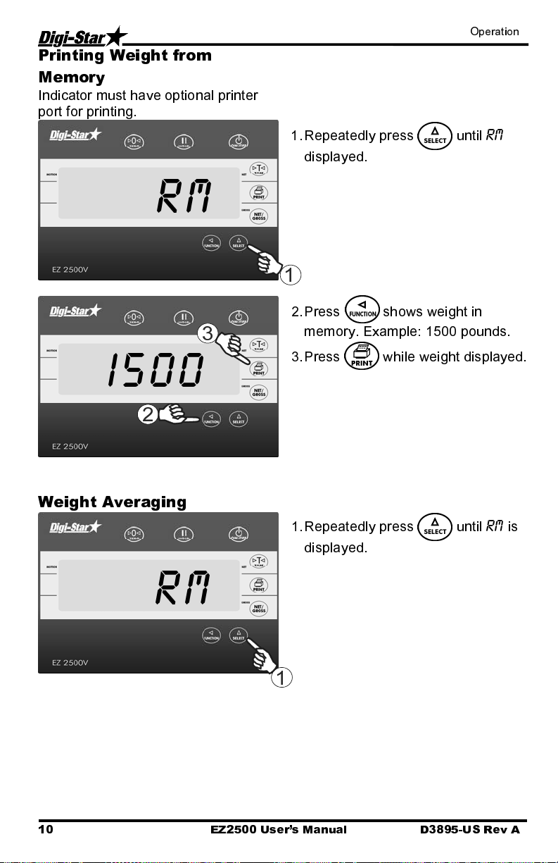
Printing Weight from
Memory
Indicator must have optional printer
port for printing.
RM
3
I500
2
Weight Averaging
1. Repeatedly press until
displayed.
1
2. Press shows weight in
memory. Example: 1500 pounds.
3. Press while weight displayed.
1. Repeatedly press until
displayed.
RM
RM
is
RM
10 EZ2500 User’s Manual D3895-US Rev A
1
Page 15

Operation
3
2. Press twice
seconds performs weight average.
within three
3. Display shows
COUNT 2
2
4
AVERAG
5
75
Printing Average Weight
750
1
D3895-US Rev A EZ2500 User’s Manual 11
individual weights to average is two.
Example weight of 1000 pounds
and 500 pounds averaged.
4. Displays
5. Display shows average of two
weights in memory. After displaying
average weight, indicator returns to
gross weight mode.
1. Press while average weight is
displayed.
Sample output format shown below:
2CT 750LB AV
Counts Average
COUNT 2
AVERAG
.
if number of
Weight
Page 16
Other Functions
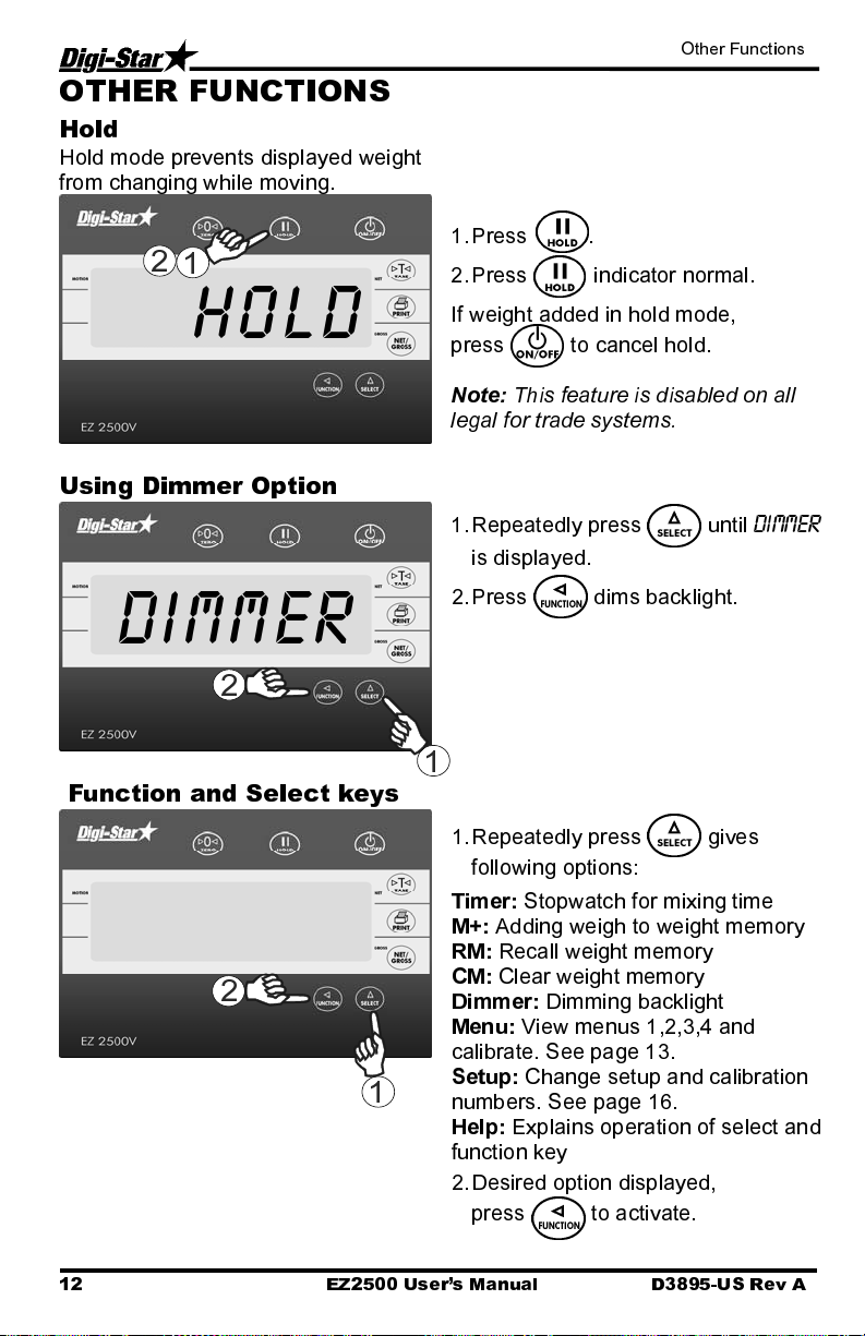
OTHER FUNCTIONS
Hold
Hold mode prevents displayed weight
from changing while moving.
2
1
1. Press .
2. Press indicator normal.
HOLD
Using Dimmer Option
DIMMER
2
Function and Select keys
2
1
If weight added in hold mode,
press to cancel hold.
Note: This feature is disabled on all
legal for trade systems.
1. Repeatedly press until
is displayed.
2. Press dims backlight.
1
1. Repeatedly press gives
following options:
Timer:
M+:
RM:
CM:
Dimmer:
Menu:
calibrate. See page 13.
Setup:
numbers. See page 16.
Help:
function key
2. Desired option displayed,
Stopwatch for mixing time
Adding weigh to weight memory
Recall weight memory
Clear weight memory
Dimming backlight
View menus 1,2,3,4 and
Change setup and calibration
Explains operation of select and
press to activate.
DIMMER
12 EZ2500 User’s Manual D3895-US Rev A
Page 17

Menus and Calibration
MENUS AND CALIBRATION
Options changed by user. To display menus 1,2,3,4 and calibrate:
1. Repeatedly press until
2.
Press .
3.
Repeatedly press selects Menu1,2,3,4 or calibrate
4.
Press displays setting name and allows value changes.
5.
Press selects options for each setting/display.
6.
Press saves setting and next option for menu displays.
SETTING
[display]
D.A.N
NO.
MENU 1. BASIC FEATURES IN MOST INDICATORS
LANGUAGE
[langag]
DISPLAY RATE
[0 rate]
ZERO TRACK
(ztrack)
WEIGH METHOD
(W mthd)
SCALE ID SETUP
(scalid)
1 PRESS ZERO
(I zero)
D3895-US Rev A EZ2500 User’s Manual 13
101
102
104
105
108 NEW EZ
115
MENU
is displayed.
OPTIONS [displayed]
BOLD=DEFAULT
English
Dutch
French
German
Italian
Portuguese
Spanish
Danish
Hungarian
Spanish
1,2,3,4
ON/
OFF
1=General,
2=Fast,
3=Slow,
4=Lock-On
ON/
OFF
[ENGLSH)
[NEDERL]
[FRANCS]
[DEUTSH]
(ITAL]
(PORT]
(ESPAN]
(DANSK]
(MAGYAR]
(VESTA]
DESCRIPTION
Select language to be
displayed.
Update display times per
second.
If ON -zero track adjust
balance for buildup of snow &
mud.
Select weigh method
Identity of scale location (truck
id or Mixer number).
If ON -press and hold Zero
key to Zero/Balance scale.
Page 18

Menus and Calibration
SETTING
[display]
TARE AUTO
PRINT
(tareap)
ONE LINE PRINT
(Il prt)
AUTO PRINT
(aprint)
PRINT FORMAT
(prtfmt)
REMOTE
(REMOTE)
ZERO OUTPUT
(zerout)
SCALE NUMBER
(scl no)
REMOTE
DISPLAY
(rmdisp)
ANALOG LOW
WEIGHT
(LOW WT)
D.A.N
NO.
OPTIONS [displayed]
BOLD=DEFAULT
MENU 2. CLOCK, PRINTER,
COMMUNICATIONS FEATURES
ON/
OFF
OFF
OFF
/OFF
211
212
214
ON/
ON/
AUTO
WTONLY
DOWNLD
DT+TM
ID+TM
IDWTTM
ANIMAL
3200-A
216
3200-B
32-TMR
DATCH1
FDINFO
WTRCTM
EIDINF
EID
EIDVID
218
ON
219
231
234
241
EZ3MUX
EZ2
DESCRIPTION
If ON -tare auto-prints
displayed weight.
If ON -indicator data prints on
one line.
If ON -pressing keys auto-
prints weight values.
Select alternate & comma
(CSV) formats.
If ON indicator communicates
with cab control display
Perform Zero/Balance for
SCOREM #11 weight output
and analog output (4-20mA)
Select scale number for cab
control communication
Select type of remote display
Enter analog weight value to
equal 4mA or 0 volts
14 EZ2500 User’s Manual D3895-US Rev A
Page 19

Menus and Calibration
SETTING
[display]
ANALOG HIGH
WEIGHT
(HIGHWT)
ANALOG SELECT
(ANAOUT)
D.A.N
NO.
242
243
OPTIONS [displayed]
BOLD=DEFAULT
DESCRIPTION
Enter analog weight value to
equal 20mA or 5 volts
Select 0-5V,4-20ma or 0-20ma
output
MENU 3. SCALE CALIBRATION SETTINGS
DISPLAY UNIT
(lb-kg)
CAPACITY
(cap)
WM1 ADJUST 1
(wmaI-I)
301
303
304 40000
.01,.02,.05,.1,.2,.5,1,2,5,
10
,20, 50,100
LB
/KG
Select display count size of
weigh values.
Display pounds -lb or
kilograms -kg
Enter MAXIMUM weight
measurable on scale.
MENU 4. PRESET, BATCHING & ROTATION COUNTER FEATURES
Does not apply to 2500 indicator
CALIBRATION
DEAD WEIGHT
CAL
(CAL)
SETUP NUMBER
(SETUP)
CALIBRATION
NUMBER
(CAL)
802
871
872
Calibration method using
weights
Quick entry method selects
weigh method 1-4lbs, 5-8 kg,
gain 1-9, display counts 1-9
and capacity *1000
Weight displayed at 0.4mV/V
for these load cells
D3895-US Rev A EZ2500 User’s Manual 15
Page 20
Menus and Calibration
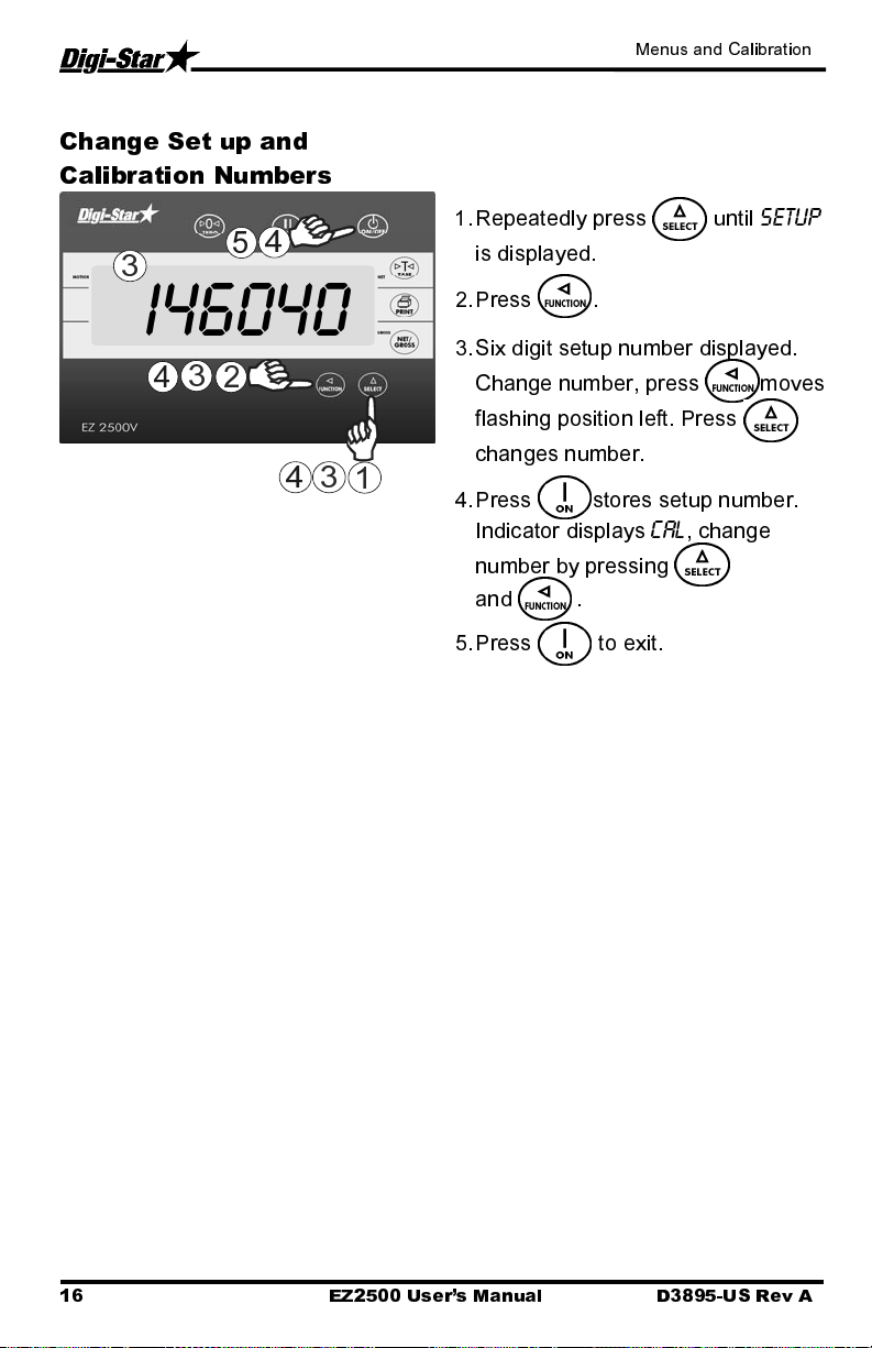
Change Set up and
Calibration Numbers
4
5
3
I46040
3
4
2
4
3
1
1. Repeatedly press until
is displayed.
2. Press .
3. Six digit setup number displayed.
Change number, press moves
flashing position left. Press
changes number.
4. Press stores setup number.
Indicator displays
number by pressing
and .
5. Press to exit.
CAL
, change
SETUP
16 EZ2500 User’s Manual D3895-US Rev A
Page 21
Installation
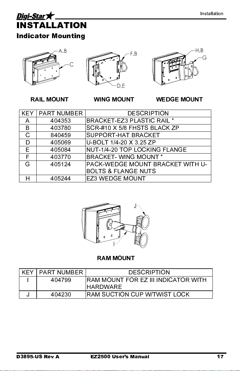
INSTALLATION
Indicator Mounting
RAIL MOUNT WING MOUNT WEDGE MOUNT
KEY PART NUMBER
A 404353 BRACKET-EZ3 PLASTIC RAIL *
B 403780 SCR-#10 X 5/8 FHSTS BLACK ZP
C 840459 SUPPORT-HAT BRACKET
D 405069 U-BOLT 1/4-20 X 3.25 ZP
E 405084 NUT-1/4-20 TOP LOCKING FLANGE
F 403770 BRACKET- WING MOUNT *
G 405124 PACK-WEDGE MOUNT BRACKET WITH U-
BOLTS & FLANGE NUTS
H 405244 EZ3 WEDGE MOUNT
RAM MOUNT
KEY PART NUMBER
I 404799 RAM MOUNT FOR EZ III INDICATOR WITH
HARDWARE
J 404230 RAM SUCTION CUP W/TWIST LOCK
DESCRIPTION
DESCRIPTION
D3895-US Rev A EZ2500 User’s Manual 17
Page 22
Installation
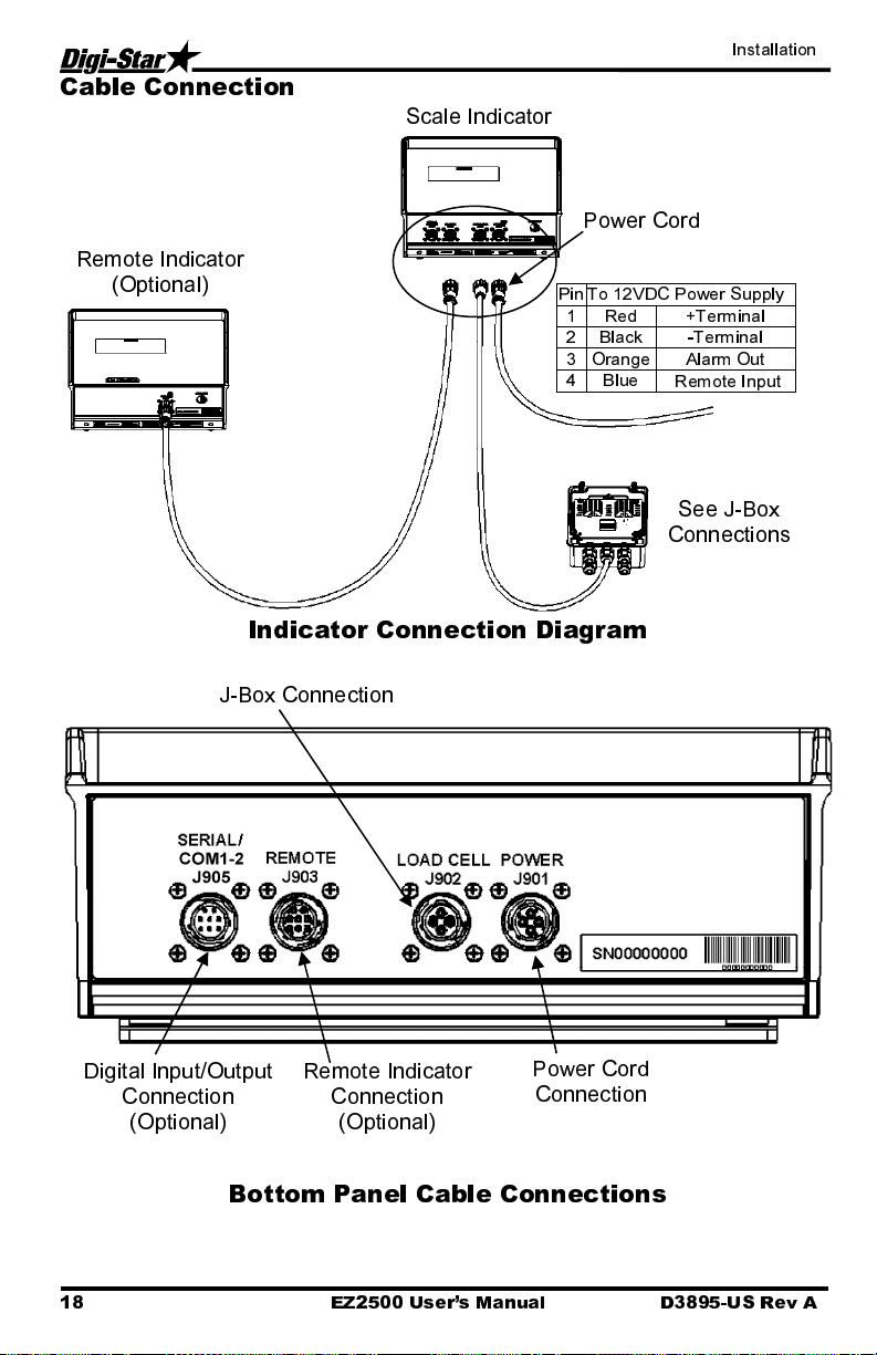
Cable Connection
Remote Indicator
(Optional)
Scale Indicator
Power Cord
Pin To 12VDC Power Supply
1 Red +Terminal
2 Black -Terminal
3 Orange Alarm Out
4 Blue
Remote Input
See J-Box
Connections
Indicator Connection Diagram
J-Box Connection
Digital Input/Output
Connection
(Optional)
Remote Indicator
Connection
(Optional)
Power Cord
Connection
Bottom Panel Cable Connections
18 EZ2500 User’s Manual D3895-US Rev A
Page 23

Installation
Connect Load Cells to J-Box
Connect load cell
wires to terminal
blocks.
See Wire Color Key
Wire Color Key
Color Description
1 White Signal +
2 Green Signal -
3 Red Excitation +
4 Black Excitation -
5 Shield Shield
Tighten Nuts
J-Box Illustrated for 4
Load Cell Installation
J-Box Cable
Connect to Indicator
bottom Panel.
Load Cell Cable
J-Box Connections
Load Cell Direction
Observe direction of arrow when installing load cell.
D3895-US Rev A EZ2500 User’s Manual 19
Page 24

Optional Equipment
OPTIONAL EQUIPMENT
Remote Indicators
RD440 small remote display
RD2500V backlit remote display with
1.7” high numbers
RD2500V backlit remote display
w/transmitter and installed receiver
RD4000 remote display
20 EZ2500 User’s Manual D3895-US Rev A
Page 25

Troubleshooting
p
)
)
g
j
TROUBLESHOOTING
FLOW CHART
START
YES
Does the indicator come on?
NO
Is the reading on the
Indicator stable?
YES
Put your weight on each
load cell. Does the indicator
respond to your weight?
YES
Are the readings
all positive? If not
Load Cell is
side down.
u
Does the scale weigh you
approx. the same over all
Load Cells? (Weight will
not be accurate
YES
Your Indicator is probably not set-up
and calibrated correctly. Check the
decal on the bottom of Indicator. It
shows what type of Load Cells the
Indicator was calibrated to. By
pressing the on key while the
Indicator is already on, you will get
the Indicator’s “Set-up” and “Cal”
numbers. See if they compare to the
set-up and calibration numbers on
the Indicator. Contact Dealer for
further information.
NO
Check all J-Box
and Load Cell
cables for cuts
or pinched/flat
spots.
NO
If your display is unstable, or
flashes “±RANGE” disconnect
the j-box cord from Indicator.
Is display still unstable?
NO
Your Indicator is probably
cables are not attached to
Remove the cover from your J-Box
Is there moisture inside the box?
Look for loose connections.
Watch your Indicator display
while moving the wires and
pressing on the circuit board
inside the J-Box. You will see
if there is a loose connection
or bad solder
YES
defective. Try another
Indicator to verify.
Be aware of electrical
interference that might
affect Indicator, such as
mobile phones, CB
radios, radio towers,
electrical motors, etc.
Make sure Load Cell
hydraulic lines or
reservoir.
NO
Note:
oint.
Poor Connection
apart and clean connections.
(Rust or paint should be wire
brushed.) Then reconnect and
tighten securely.
Bad Battery:
(weak battery may test good if
tested with no load on battery)
Bad Power Cord:
red wire is connected to (+)
positive side and black wire is
connected to (-) negative side.
When using a multimeter to
check for voltage, measure
between pin 1 (pos) and pin 2
(neg). Meter should read
between 10.5 and 14.5 volts
DC if using a tractor power
cord, black wire is positive and
white wire is negative.
Bad Indicator:
Indicator. (Even a different
model or set-up should come
Dry out your J-Box (use a
hairdryer). Check cable
strain reliefs for tightness.
Cables have drip loops. Is
asket damaged?
lid
: Take them
Replace battery
Make sure
Try another
on.
YES
Fix or replace the J-Box
Did the J-Box have a bad
YES
connection or loose wire?
NO
See next Page
D3895-US Rev A EZ2500 User’s Manual 21
Page 26

Troubleshooting
,
y
p
p
FLOW CHART
Continued
1. Disconnect all the Load Cell
wires from the terminal blocks
inside the J-Box (leave the
Indicator on while connecting
and disconnecting the wires, it
will not damage Load Cells or
Indicator if wires are shorted
during this step). Is reading on
Indicator stable?
NO
Replace J-Box
(be aware of electrical
interference that might affect
your scale such as: mobile
phones, CB radios, radio
electric motors, etc.).
towers
4. Record the Indicator reading with
the Load Cell connected.
5. Stand or hang your weight over the connected
Load Cell. Record how much the weight
increased with your weight over the Load Cell. (A
scale with only one Load Cell will weigh heavy.)
2. Zero balance the Indicator.
(Press “NET/GROSS” then
“ZERO”). Indicator should display
“0”.
YES
Note:
Hook up the Load Cells to the J-Box one at
a time (only one Load Cell connected at a time).
This will get a reading for each Load Cell. While
performing this test, watch for any other
symptoms such as erratic/unstable display.
Indicator flashing “±RANGE”, negative reading,
etc. If the Indicator reading should ever appear
abnormal with any Load Cell connected then it is
probably bad.
3. Connect one Load Cell back into one of the
terminals in the J-Box. (The reading you get for
each Load Cell is dependent on the size and type
of each Load Cell and how much weight is over
each Load Cell. In general, the number should be
Note:
that’s verification on the J-Box is OK. If the
scale did not respond, either that Load Cell is
bad or the J-Box is bad. Try the other Load
Cells. If the Indicator still shows no response,
positive and stable.)
If the scale responded to your weight,
the J-Box is bad. (Replace J-Box)
6. Disconnect the first Load Cell and reconnect
7. Repeat step 6 for the remaining Load Cells.
Remember to record
our readings.
a second one. Record the Indicator reading.
Stand or hang your weight over the connected
Load Cell. Record how much the weight
increased.
Do not expect the Load Cells to give the same
reading. It is common for Load Cells to have
readings that vary by hundreds, even thousands.
ecially when one is carrying more weight.
Es
8. Bad Load Cells will have a reading that is
either unstable, makes the indicator flash
“±RANGE” or is more than three times greater
or less than the average of the others. Also the
readings of your weight over each Load Cell
should be similar. (Probably 4 times your actual
weight). Any differences could be an indication
of a bad Load Cell or a structural
roblem.
22 EZ2500 User’s Manual D3895-US Rev A
 Loading...