

Page 1
ERM-2.4
OPERATORS MANUAL
Ft. Atkinson, Wisconsin USA
Panningen, The Netherlands
www.digi-star.com
D3986-US Rev A December 14, 2013
Page 2

ERM-2.4 Operators Manual
INTRODUCTION
Thank you for purchasing the ERM-2.4 External Radio MODEM. This
device allows you to add radio capability to any indicator with a J905 port
for communicating to devices such as the Cab Control 2.4. The easy
installation of the ERM-2.4 makes it a seamless process to configure your
indicator to be used as a wireless device. Simply plug the ERM-2.4 into the
J905 port, turn on the External Radio setting in Menu 2, configure the radio
channel and you’re ready to go!*
* Indicator must have 8J or newer software installed.
2
Page 3
ERM-2.4 Operators Manual
DESCRIPTION
PART NO.
QTY
RADIO-ERM-2.4
409004
1
FASTENER-HOOK AND LOOP 2.25”
406711
4
CONTENTS
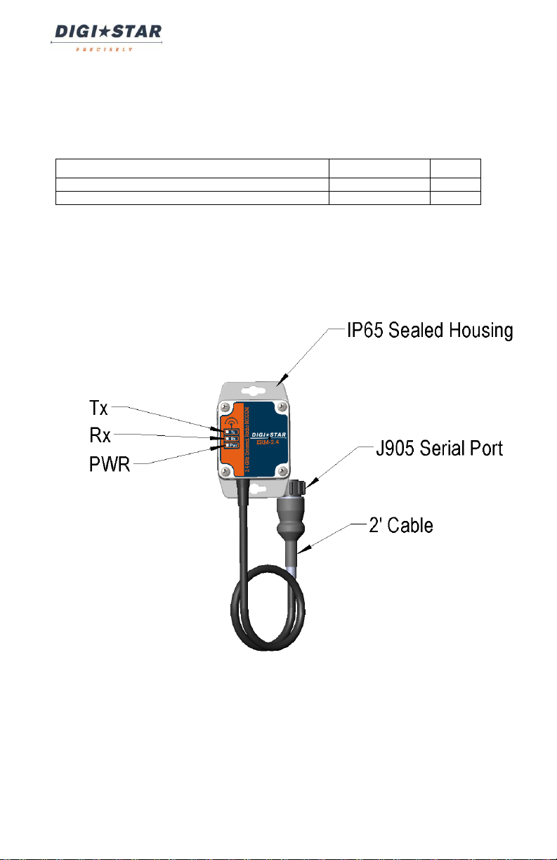
OVERVIEW
Figure 1. System Diagram
3
Page 4

ERM-2.4 Operators Manual
SUGGESTED MOUNTING LOCATIONS
Figure 2. Mounting Options – Hook and Loop Fasteners
NOTE: To increase range, the ERM-2.4 may also be used with the 409156
extension cable and mounted on the implement in the vertical position
(cable side down) as shown in Figure 2.
4
Page 5

ERM-2.4 Operators Manual
Figure 3. Mounting Options – Bolted
5
Page 6

ERM-2.4 Operators Manual
Figure 3. Incorrect Mounting Position
NOTE: To increase range, the ERM-2.4 may also be used with the 409156
extension cable. Orienting the unit in the horizontal position (cable side
horizontal) as shown in Figure 3 is not recommended.
6
Page 7

ERM-2.4 Operators Manual
INSTALLATION INSTRUCTIONS
1. If mounting the ERM-2.4 using the supplied hook and loop
fasteners:
a. See “Suggested Mounting Locations” for proper mounting
positions.
b. Wipe the mounting surface clean of dirt and debris.
c. Wipe the adhering surface and back side of ERM-2.4 clean with
alcohol or cleaner spray and allow to air dry.
d. Apply hook and loop fasteners as necessary.
e. Allow unit to cure for 12-24 hours before use.
NOTE: Adhesive will not stick to any surface at temperatures below
freezing. Install at room temperature for best results.
2. If mounting the ERM-2.4 using bolts:
a. Determine the proper sized bolt for use with connecting the ERM-
2.4 to the equipment.
b. See “Suggested Mounting Locations” for proper mounting
configurations.
NOTE: Installing the ERM-2.4 in positions other than shown will decrease
radio range and performance.
7
Page 8

ERM-2.4 Operators Manual
INDICATOR SETUP INSTRUCTIONS
To utilize the External Radio feature:
1. Make sure the indicator has a J905 port installed.
a. If no J905 serial port is installed, the indicator must be sent in for
an upgrade.
NOTE: The ERM-2.4 is not compatible with J904 indicators.
2. Ensure that the software running on the scale Indicator is compatible
with the ERM-2.4.
a. To check the current software version, press “ON” momentarily.
b. Continue to read the display until it shows “PRGID”. Any version
that displays 8J or newer is compatible. (For example 8N would
be compatible).
3. To activate the External Radio feature, from the Indicator, set EXTRAD
in Menu 2 (D.A.N. 229) to "ON".
4. To set up the radio channel, refer to the “Setting up the Indicator”
section of the Cab Control 2.4 manual.
NOTE: The ERM-2.4 is not compatible with legacy wireless Digi-Star
products.
8
Page 9
ERM-2.4 Operators Manual
AGENCY APPROVALS
United Stated of America
FCC
ID: OUR-XBEE/OUR-XBEEPRO
Contains Model XBee-PRO Radio
The enclosed device complies with Part 15 of the FCC Rules. Operation is
subject to the following two
conditions: (i.) this device may not cause harmful interference and (ii.) this
device must accept any interference received, including interference that may
cause undesired operation.
Canada
Industry Canada
Contains Model XBee-PRO Radio, IC: 4214A-XBEEPRO
Europe
ETSI
Japan
MIC
ID: 005NYCA0378
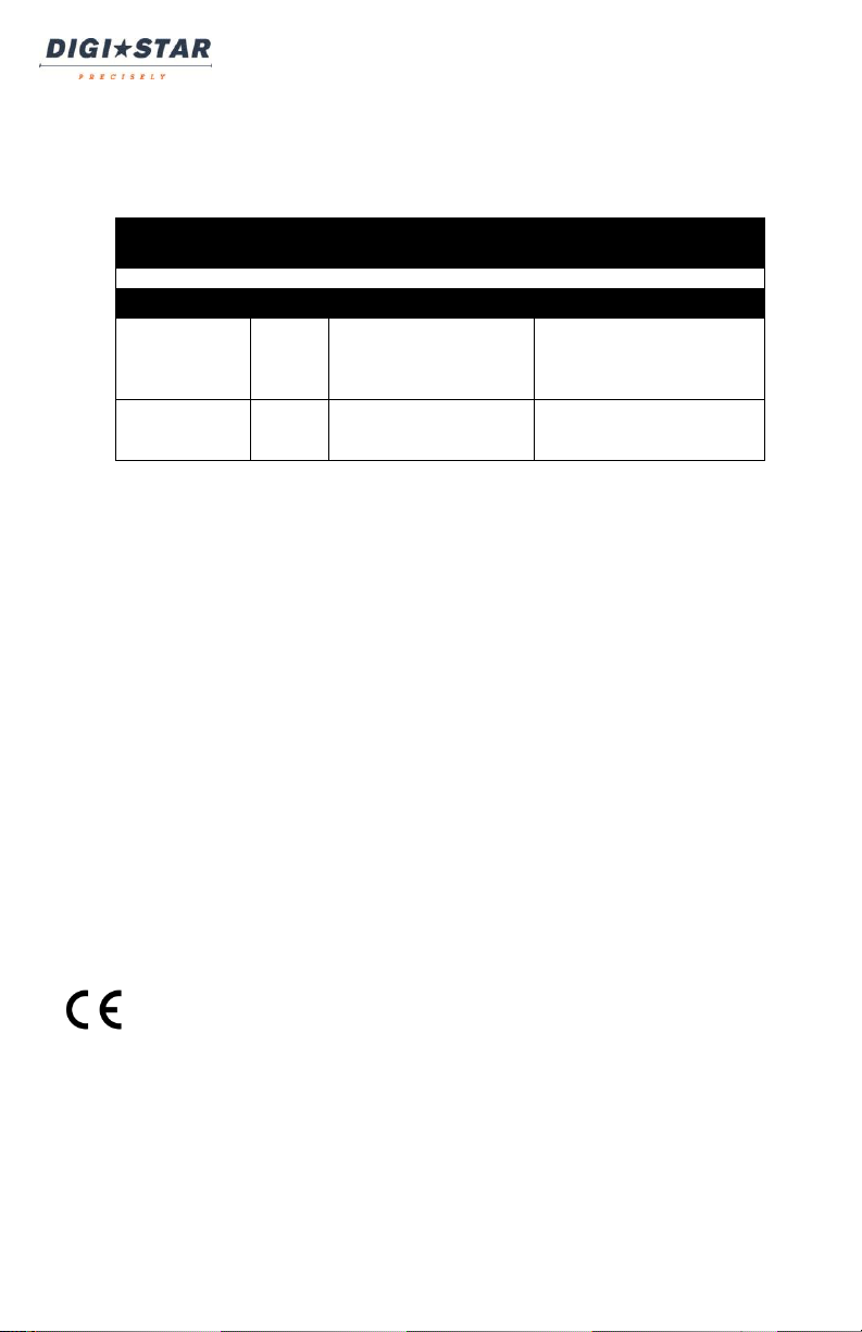
SETTING
[display]
D.A.N
NO.
OPTIONS [displayed]
BOLD=DEFAULT
DESCRIPTION
MENU 5. CONTROL SETTINGS
External Radio
(EXTRAD)
229
ON
ON enables the External
Radio feature. Note: This
feature automatically turns
RADIO to “ON”.
Scale Number
(SCLNO)
231
Select 1 – 24
Sets the scale number to
the desired channel (up to
24 channels).
DEFAULT SETTINGS
9
Page 10

ERM-2.4 Operators Manual
ERM-2.4 is not turning ON.
Ensure power is plugged into indicator.
Ensure indicator is powered ON.
Ensure that a J905 port is installed on
the Indicator and PWR LED is ON.
Ensure the indicator is running 8J or
newer.
Ensure Indicator settings are
configured to work with the ERM-2.4
ERM-2.4 is not
communicating with Cab
Control 2.4
Ensure radio channel is set properly.
Ensure ERM-2.4 is connected properly
to J905 and PWR LED is ON.
Ensure that red Tx diagnostic LED is
blinking approx. 10 times per second.
TESTING THE SYSTEM:
1. To test the system, check the following:
a. The red Tx LED (as shown in Figure 1) should flash at a rate of
approximately 10 times per second.
b. The Cab control should show what is displayed on the Indicator.
c. When the Cab Control 2.4 “ZERO” button is pressed, the Rx LED on
the ERM-2.4 should illuminate briefly and the indicator should display
“ZERO”.
NOTE: Failure to install the ERM-2.4 system properly will result in decreased
range or performance. Refer to the “Suggested Mounting Locations” section for
more details.
TROUBLESHOOTING:
Technical Support Hotline: 1(920)-563-9700
10
Page 11

NOTES:
ERM-2.4 Operators Manual
11
 Loading...